Article

A Study on the Rotor Design of Line Start Synchronous Reluctance Motor for IE4 Efficiency and Improving Power Factor

1
Department of Electrical Engineering, Hanyang University, Seoul 04763, Korea
2
Department of Electrical Engineering, Dongyang Mirae University, Seoul 08221, Korea
3
Electric Machines and Drives Research Center, Korea Electrotechnology Research Institute, Changwon 51543, Korea
*
Author to whom correspondence should be addressed.
Energies 2020, 13(21), 5774; https://doi.org/10.3390/en13215774
Submission received: 15 October 2020 / Revised: 2 November 2020 / Accepted: 3 November 2020 / Published: 4 November 2020

Abstract

:
As international regulations of motor efficiency are strengthened, the line-start synchronous reluctance motor (LS-SynRM) is being studied to improve the efficiency of the electrical motor in industrial applications. However, in industrial applications, the power factor is also an important performance index, but the LS-SynRM has poor power factor due to the saliency characteristic. In this paper, the rotor design of LS-SynRM is performed to improve the efficiency and power factor. First, the barrier design is performed to improve the efficiency and power factor using the response surface method (RSM). Second, the rotor slot design is performed according to the length of bar for synchronization. Lastly, the rib design is performed to satisfy the power factor and the mechanical reliability. The final model through the design process is analyzed using finite element analysis (FEA), and the objective performance is satisfied. To verify the FEA result, the final model is manufactured, and experiment is performed.

Graphical Abstract

1. Introduction

In industrial applications, electrical energy consumption of motors account for 35% to 40% of electrical energy generated in the world. If this electrical energy consumption can be reduced, several environmental impacts, such as the emissions of CO2 or global warming, can be reduced [1,2]. For this reason, international regulations regarding motor efficiency were enacted by the International Electrotechnical Committee (IEC) 60034-30. According to IEC 60034-30, motor efficiency was classified as IE1 to IE5. Recently, the efficiency standards of industrial applications have been strengthened, and industrial motors may need to meet IE4 or IE5 efficiency class [3].
With various types of motors, the three-phase squirrel-cage induction motor (SCIM) is the most used, because of its simple structure, line-start ability, robustness, and low manufacturing cost. However, it is evident that the induction motor (IM) does not meet high efficiency due to rotor copper loss [4,5,6]. Due to a global trend on improving the efficiency of electric motors, there is ongoing research that focuses on this area. In References [7,8], the aluminum in the rotor slot is replaced by copper to reduce the rotor copper loss. Copper die-casting induction motors can improve efficiency by about 2–3% compared to the aluminum die-casting induction motors. However, copper has a higher melting point than aluminum, so a die-casting process is difficult, and the manufacturing cost increases. In industrial variable-speed applications, a variable-speed drive (VSD) is used to improve the efficiency of motors [9,10,11]. When using the VSD system, a synchronous motor can be controlled to improve the efficiency. However, the synchronous motor along with the VSD system is more expensive than SCIMs.
Line-start synchronous machines (LSSMs) are actively studied because they can meet the efficiency of IE4. In addition, a LSSM is direct-on-line (DOL) motor, such as IM, so it does not require an inverter, in which the cost of electric system can be reduced [12,13,14,15,16,17]. LSSM can be classified into two types; line-start permanent magnet synchronous motor (LSPM) and line-start synchronous reluctance motor (LS-SynRM). LSPM has the high efficiency and power factor because of the permanent magnet. However, the permanent magnet of LSPM must use a rare-earth magnet, such as neodymium, because of the high starting current. Furthermore, the resources of rare-earth magnets are limited, and lead to high costs [18,19]. Therefore, the LS-SynRM has received attention for its high efficiency and for the fact that it does not use a rare-earth magnet.
A reactive power of an electrical motor depends on the power factor. If the reactive power is increased by the low power factor, the copper loss in stator winding increases under the same output power and input voltage condition because of the current increases [20]. This increased copper loss decreases the efficiency of the electrical motor. For this reason, there are the power factor standards of industrial motors, according to IEC 60034. The electrical motor must meet the power factor standards to use industrial applications [21]. However, LS-SynRM has a lower power factor than IM and LSPM because of a saliency characteristic and may not meet the power factor standards [22,23,24]. Therefore, the design method considering the power factor is required.
This paper is a design process of LS-SynRM, for super premium efficiency, and for improving the power factor. The efficiency and the power factor of LS-SynRM is determined by dq-axis inductance, which is determined by the barrier design. Therefore, the design parameters are selected for IE4 efficiency and the power factor. Based on the selected design parameters, the barrier optimal design is performed using the response surface method (RSM) and finite element analysis (FEA). In addition, the rotor slot design is performed for synchronization and the rib design is performed to improve the power factor and satisfy the mechanical reliability through the safety factor. To verify the efficiency and the power factor of the design result, the final model is manufactured, and the experiment is performed to verify the IE4 efficiency and power factor.
This paper is organized as follows. In Section 2, the characteristics of LS-SynRM are discussed in respect to the structure and the operation in asynchronous and synchronous speed. In Section 3, the characteristic of the reference machine is analyzed. In Section 4, the design of LS-SynRM is performed using RSM and FEA and the final model is analyzed using FEA. In Section 5, to verify FEA results, the experiment is performed and the results of LS-SynRM are compared with FEA results. Finally, Section 6 contains the conclusion.

2. Characteristic of LS-SynRM

2.1. Structure of LS-SynRM

Figure 1 shows the rotor structure of a general LS-SynRM. LS-SynRM has a structure in which the squirrel cage slots are placed on the outer side of the rotor, and the barrier is arranged on the inner side of the rotor. Because of this structure, LS-SynRM operates as IMs at the asynchronous speed and as SynRM at the synchronous speed. Moreover, the rotor design of LS-SynRM is classified as a rotor slot and barrier. The rotor slot design determines a starting characteristic of LS-SynRM and the barrier design determines the performance of LS-SynRM, such as the efficiency and power factor. Therefore, the rotor slot design is important to reach the synchronous speed, and the barrier design is important to satisfy the super-premium efficiency (IE4).

2.2. Asynchronous Speed

In asynchronous speed, the LS-SynRM has the slip, which generates an induced voltage on a conductor in a rotor slot. An induced current that is generated by the induced voltage provides the magnetic torque that LS-SynRM can be synchronization. Moreover, in case of the LS-SynRM, the reluctance torque is generated due to a saliency difference, which is the difference between dq-axis inductance. Therefore, the torque of LS-SynRM is expressed as Equation (1) [25,26].
T e = T c a g e + T r e l sin ( 2 s ω t + α )
where Te is the torque of LS-SynRM at asynchronous speed, Tcage is the magnetic torque generated by the induced current, Trel is the amplitude of reluctance torque produced by the saliency, s is slip, ω is the electrical angular frequency, and α is the phase angle of pulsating torque.
The magnetic torque is constant and depends on the slip as in the induction motor, and the average of reluctance torque is zero, but this torque pulsates twice the slip frequency. Figure 2 shows a speed-torque curve of LS-SynRM at an asynchronous speed. The amplitude of the pulsating torque and the average torque depend on the slip. In a synchronous speed, the maximum torque is called the pull-out torque, which is the maximum load torque that can be synchronized [26].

2.3. Synchronous Speed

At a synchronous speed, there are no eddy currents in the rotor slot because the slip is zero. Therefore, the LS-SynRM is operated as the synchronous reluctance motor and the efficiency is improved compared to SCIM due to the secondary copper loss. The efficiency of LS-SynRM is expressed as follows.
η = P o u t P i n = P o u t P o u t + P l o s s = T e ω e T e ω e + P c o p p e r + P c o r e T e = 3 2 P 2 ( L d L q ) I a 2 sin 2 β
where η is the efficiency, Pout is mechanical power, Pin is electrical input power, Ploss is total loss of motor, Te is torque of motor, ωe is synchronous speed, Pcopper is copper loss, and Pcore is core loss, P is the number of pole, Ld and Lq are d-, q-axis inductance, respectively, Ia is the current, and β is the current phase angle.
The efficiency is determined by the reluctance torque, the core loss, and the copper loss. The core loss depends on the magnetic flux density and input frequency, which is determined when designing electric machines. Therefore, the copper loss must be reduced to improve the efficiency. This should increase the torque per current, which should increase the rotor saliency difference.
The power factor of the LS-SynRM is determined by the phase difference between the voltage and current. Figure 3a shows a vector diagram of the LS-SynRM, and the power factor of LS-SynRM can be expressed as follows.
cos φ = ρ 1 ρ 2 cos 2 β + 1 sin 2 β , ρ = L d L q
where cosφ is the power factor, and ρ is the saliency ratio.
The power factor is determined by the saliency ratio and the current phase angle. Figure 3b shows the power factor according to the saliency ratio and the current phase angle. The power factor increases as the saliency ratio increases. Therefore, the saliency difference and ratio are important design parameters for IE4 efficiency and improving the power factor.

3. Reference Machine

In order to compare the efficiency and power factor of LS-SynRM, 2.2 kW four pole IM is selected as the reference motor. Figure 4 show the FEA model and Table 1 shows the specification of reference machine. ANSYS Maxwell was used to analyze the performance of the reference machine.
Table 2 shows the FEA and experiment results of the reference machine. The efficiency of the reference machine is 90.7% that is IE3 efficiency according to IEC 60034. Because IE4 efficiency is 91%, the reference machine does not satisfy IE4 efficiency. In general, the induction motor has the rotor copper loss due to the slip, and this loss accounts for 23% of total losses in Table 2. If the rotor copper loss is reduced, the efficiency of the electrical machine can satisfy IE4 efficiency. LS-SynRM does not have the rotor copper loss because this motor is operated at a synchronous speed, where slip is zero. Therefore, LS-SynRM can satisfy IE4 efficiency, and the design process of LS-SynRM has studied to improve the efficiency.

4. Design of LS-SynRM
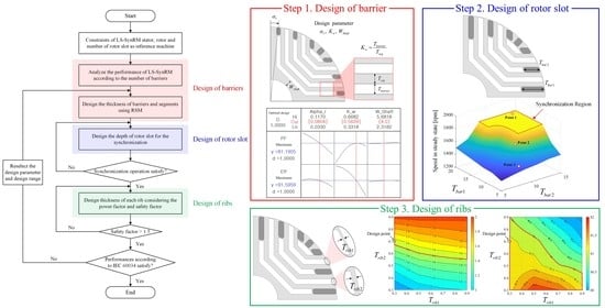
4.1. Design Process

Figure 5 shows the design process of LS-SynRM for IE4 efficiency and improving the power factor. The stator, rotor, and number of rotor slot are constrained under the same conditions as the reference machine. The main design process is three steps. First, the design of the barrier is performed to improve the efficiency and power factor using RSM. The efficiency and power factor of LS-SynRM are determined by the saliency difference and ratio. Therefore, there are two steps in the design of the barriers: the number of barriers and thickness of barriers and segments. Second, the design of the rotor slot is performed to reach LS-SynRM into the synchronous speed. Because synchronization is determined by the resistance and leakage inductance of the rotor bar, the design is performed according to the depth of the rotor slot. Lastly, the design of each rib is performed considering the power factor and mechanical reliability. The thickness of the ribs affects the leakage flux, which affect the performance of LS-SynRM, and is determined by the thickness of each rib. Therefore, the thickness of each rib must be designed considering the performance and safety factor. If the efficiency and power factor does not satisfy, the design parameter and range are reselected, and RSM is performed to satisfy the performance. Table 3 shows IEC 60034 standard and the design objective of the efficiency and power factor. Considering the margin based on Table 2, FEM performance is selected as 91.5% efficiency and 81% power factor.

4.2. Design of Barrier

From Equation (3), the power factor of LS-SynRM is determined by the saliency ratio, which is ratio d-axis inductance to q-axis inductance. The dq-axis inductances are determined by the number of barriers and thickness of flux barrier and segments [27]. Therefore, the barrier design is performed according to the number of barriers and thickness of flux barrier and segments.

4.2.1. Number of Barrier

Figure 6 shows the FEA model according to the number of barriers. The number of rotor slots is the same as the reference machine, and the total length of barrier and segment is constant, for comparison under the same conditions. Furthermore, for each layer of each model, the thickness of the barrier and segment are compared equally. Table 4 shows the comparison of the dq-axis inductances, the saliency ratio, the power factor, and efficiency under the rated current condition. From Table 4, the larger the saliency ratio, the larger the power factor. Moreover, the efficiency of each model satisfies more than IE4 efficiency. Therefore, the design of the barrier, according to the thickness of the flux barrier and segments, is performed based on model 3.

4.2.2. Thickness of Flux Barriers and Segments

To maximize the power factor, the optimal design is performed using RSM and FEA. Figure 7 shows the design parameters for the optimal design [28]. The range of design parameters is selected within the rotor constraints, as shown in Table 5. Furthermore, the objective function is maximizing the power factor and the efficiency. Figure 8a shows the RSM result and Figure 8b shows the optimal design result. Table 6 shows the optimal design result. In Table 6, RSM and FEA results are similar, so the optimal result is valid.

4.3. Design of Rotor Slot

In general, the starting characteristic is determined by the rotor resistance and leakage inductance. This rotor resistance and leakage is determined by the depth and thickness of the rotor slot. However, the barriers are constraints on the thickness and depth of the rotor slot. Therefore, for synchronization, the design parameters of the rotor slot are determined, as shown in Figure 9a. In order to analyze synchronization, the analysis, according the selected design parameters, is performed by the time-step FEA, which is the mechanical and electromagnetic transient analysis [29,30], considering inertia of LS-SynRM. Figure 9b shows the time step FEA result. The synchronization region is determined by the depth of the rotor slot. Figure 10 shows the time step FEA result for the three selected points. If synchronization fails, the torque and speed pulsate. As a result, the design parameter is determined as Tbar1 = 20 (mm) and Tbar2 = 13 (mm).

4.4. Design of Ribs

When LS-SynRM rotates, the centrifugal force is focused on the outer rib. If the thickness of the outer rib is designed to be small, the LS-SynRM is mechanically damaged during operation. Therefore, the design of rib must be performed for use as the industrial application. However, the thickness of the outer rib also affects the power factor, so the design of the rib is performed considering the power factor and mechanical reliability. The mechanical reliability is determined by a safety factor, as shown in the following equation. Generally, the mechanical reliability is ensured if the safety factor is higher than 1.5 [31].
SF = σ yield σ max
where SF is the safety factor, σyield is the tensile yield strength of material, σmax is the stress of material during rotation.
Because of the structure of LS-SynRM, there are several bridges that reduce the mechanical stress at the rib. Therefore, the design parameters are selected, as shown in Figure 11. Considering the manufacture, the design parameters are designed to be 0.3 (mm) or more. Figure 12 shows the power factor and the safety factor, according to the design parameters. As the thickness of each rib increases, the power factor is reduced because the leakage magnetic flux is increased. Furthermore, the safety factor is increased due to reduced mechanical stress. Considering the objective performance in Table 3, the design parameters are designed as Trib1 = 0.3 (mm) and Trib2 = 0.7 (mm).

4.5. Design Result

Figure 13 shows the design result through the design process of LS-SynRM. Table 7 shows the FEA result of LS-SynRM. The efficiency of LS-SynRM is 91.7% and the power factor of LS-SynRM is 81.2%. Compared with Table 2, the efficiency is improved about 0.5%, but the power factor is decreased about 2.6% than the reference machine. The efficiency satisfies the IE4 efficiency and the power factor satisfies the IEC 60034 standard for the industrial application. Therefore, the LS-SynRM can improve the efficiency compared with IM and be used as an industrial electric machine.

5. Experimental Validation

5.1. Manufacture of LS-SynRM

To verify the FEA result, the designed LS-SynRM is manufactured. Figure 14a shows the rotor core of the manufactured LS-SynRM. A die-casting process is performed to inject the melted aluminum into the rotor slot. During the die-casting process, a high press is applied to the rotor slot so that the melted aluminum is injected in the rotor slot. Figure 14b shows the endplate, which is required to prevent the melted aluminum from being injected into the barrier. Figure 14c shows the cross-section of the rotor and the aluminum is filled in the rotor slot. Figure 14d shows the rotor with the end-ring. The width of the end-ring is the same as the reference machine and the height of the end-ring is the difference between the deepest rotor slot depth and the outer diameter of the rotor.

5.2. Experiment Result

The experiment is performed to verify the FEA result. Figure 15 shows the experiment environment. The dynamometer motor is induction motor as 2.2 kW load. Using voltage and frequency control, LS-SynRM runs up and reaches a synchronous speed. After the LS-SynRM reaches a synchronous speed, the load torque is applied through the dynamometer motor to measure the efficiency and power factor of LS-SynRM. In the power analyzer, the efficiency and power factor are calculated using measured voltage, current, torque, and speed. Table 8 shows the comparison of FEA and the experiment result of LS-SynRM. When comparing the experiment and FEA results, the experiment current increases by about 5% than the FEA current. This reduces the power factor and increases the copper loss, as shown in Table 8. The power factor of FEA and experiment is 81.2% and 77.3%, respectively. However, the efficiencies of FEA and the experiment are similar because the total losses are similar. As a result, it is confirmed that the IE4 class efficiency and the power factor in IEC 60034 is satisfied.

6. Conclusions

In this paper, the design method of LS-SynRM is studied to satisfy the efficiency and power factor of IEC 60034 standard. In addition, LS-SynRM is designed considering the mechanical reliability for use in the industrial application. The performance of LS-SynRM is analyzed according to several design parameters, such as the number of barriers, the thickness of the barriers, and the segments, the depth of the rotor slot, and thickness of each rib. The design of the barrier is performed to satisfy the performance of LS-SynRM using RSM. The design of the rotor slot is performed, and the synchronization region is determined by the depth of the rotor slot. The design of each rib is performed, and the thickness of each rib is designed considering the power factor and the safety factor. Considering the efficiency, the power factor, and the safety factor, the optimal LS-SynRM is designed. The final LS-SynRM satisfies the efficiency of 91.7%, the power factor of 81.2%, and the safety factor 1.56. The final LS-SynRM is manufactured and the experiment is performed to verify the FEA result. As a result, the efficiency and power factor satisfy the IEC 60034 standard.

Author Contributions

Conceptualization, H.K.; methodology, H.J.; validation, S.-T.O.; formal analysis, H.K. and S.-T.O.; investigation, H.K. and Y.P.; resources, S.-H.W.; data curation, Y.P.; writing—original draft preparation, H.K.; writing—review and editing, S.-T.O. and H.J.; supervision, S.-H.W. and J.L.; project administration, J.L.; funding acquisition, Y.-D.C. and S.-H.W. All authors have read and agreed to the published version of the manuscript.

Funding

This research was funded by the Korea Agency for Infrastructure Technology Advancement (KAIA) grant funded by the Korea government Ministry of Ministry of Land, Infrastructure and Transport (20CTAP-C157784-01) and in part by a Korea Institute of Energy Technology Evaluation and Planning grant funded by the Korea government (20192010106780, A Construction and Operation of Open Platform for Next-Generation Super Premium Efficiency (IE4) Motors).

Conflicts of Interest

The authors declare no conflict of interest.

References

  1. Almeida, A.T.D.; Ferreira, F.J.T.E.; Baoming, G. Beyond Induction Motors-Technology Trends to Move Up Efficiency. IEEE Ind. Appl. 2014, 50, 2103–2114. [Google Scholar]
  2. Almeida, A.T.D.; Ferreira, F.J.T.E.; Duarte, A.Q. Technical and Economical Considerations on Super High-Efficiency Three-Phase Motors. IEEE Ind. Appl. 2014, 50, 1274–1285. [Google Scholar]
  3. Ferreira, F.J.T.E.; Baoming, G.; Almeida, A.T.D. Reliability and Operation of High-Efficiency Induction Motors. IEEE Ind. Appl. 2016, 52, 4628–4637. [Google Scholar]
  4. Rafajdus, P.; Hrabovcova, V.; Lehocky, P.; Makys, P.; Holub, F. Effect of Saturation on Field Oriented Control of the New Designed Reluctance Synchronous Motor. Energies 2018, 11, 3223. [Google Scholar] [CrossRef] [Green Version]
  5. Aguba, V.; Muteba, M.; Nicolae, D.V. Transient Analysis of a Start-up Synchronous Reluctance Motor with Symmetrical Distributed Rotor Cage Bars. In Proceedings of the 2017 IEEE AFRICON, Cape Town, South Africa, 18–20 September 2017. [Google Scholar]
  6. Xie, Y.; Pi, C.; Li, Z. Study on Design and Vibration Reduction Optimization of High Starting Torque Induction Motor. Energies 2019, 12, 1263. [Google Scholar] [CrossRef] [Green Version]
  7. Kim, D.-J.; Hong, D.-K.; Choi, J.-H.; Chun, Y.-D.; Woo, B.-C.; Koo, D.-H. An Analytical Approach for a High Speed and High Efficiency Induction Motor Considering Magnetic and Mechanical Problems. IEEE Trans. Magn. 2013, 49, 2319–2322. [Google Scholar] [CrossRef]
  8. Zhang, Q.; Liu, H.; Zhang, Z.; Song, T. A Cast Copper Rotor Induction Motor for Small Commercial EV Traction: Electromagnetic Design, Analysis, and Experimental Tests. CES Trans. Electr. Mach. Syst. 2018, 2, 417–424. [Google Scholar] [CrossRef]
  9. Kazakbaev, V.; Prakht, V.; Dmitrievskii, V.; Ibrahim, M.N.; Oshurbekov, S.; Sarapulov, S. Efficiency Analysis of Low Electric Power Drives Employing Induction and Synchronous Reluctance Motors in Pump Applications. Energies 2019, 12, 1144. [Google Scholar] [CrossRef] [Green Version]
  10. Aarniovuori, L.; Kolehmainen, J.; Kosonen, A.; Niemela, M.; Chen, H.; Cao, W.; Pyrhonen, J. Application of Calorimetric Method for Loss Measurement of a SynRM Drive System. IEEE Trans. Ind. Electron. 2016, 64, 2005–2015. [Google Scholar] [CrossRef] [Green Version]
  11. Goetzler, W.; Sutherland, T.; Reis, C. Energy Savings Potential and Opportunities for High Efficiency Electric Motors in Residential and Commercial Equipment; United States Department of Energy: Washington, DC, USA, 2013. [Google Scholar]
  12. Ghoroghchian, F.; Aliabad, A.D.; Amiri, E. Design improvement of dual-pole LSPM synchronous motor. IET Electr. Power Appl. 2019, 13, 742–749. [Google Scholar] [CrossRef]
  13. Ghahfarokhi, M.M.; Aliabad, A.D.; Boroujeni, S.T.; Amiri, E.; Faradonbeh, V.Z. Analytical modelling and optimization of line start LSPM synchronous motors. IET Electr. Power Appl. 2020, 14, 398–408. [Google Scholar]
  14. Mingardi, D.; Bianchi, N. Line-Start PM-Assisted Synchronous Motor Design, Optimization, and Tests. IEEE Trans. Ind. Electron. 2017, 64, 9739–9747. [Google Scholar] [CrossRef]
  15. Liu, H.C.; Lee, J. Optimum Design of an IE4 Line-Start Synchronous Reluctance Motor Considering Manufacturing Process Loss Effect. IEEE Trans. Ind. Electron. 2018, 65, 3104–3114. [Google Scholar] [CrossRef]
  16. Tampio, J.; Kansakangas, T.; Suuriniemi, S.; Kolehmainen, J.; Kettunen, L.; Ikaheimo, J. Analysis of Direct-On-Line Synchronous Reluctance Machine Start-Up Using a Magnetic Field Decomposition. IEEE Trans. Ind. Appl. 2017, 53, 1852–1859. [Google Scholar]
  17. Liu, H.-C.; Hong, H.-S.; Cho, S.; Lee, J.; Jin, C.-S. Bubbles and Blisters Impact on Diecasting Cage to the Designs and Operations of Line-Start Synchronous Reluctance Motors. IEEE Trans. Magn. 2017, 53, 8202504. [Google Scholar] [CrossRef]
  18. Dent, P. Rare earth elements and permanent magnets. J. Appl. Phys. 2012, 111, 07A721. [Google Scholar] [CrossRef] [Green Version]
  19. Goss, J.; Popescu, M.; Staton, D. A comparison of an interior permanent magnet and copper rotor induction motor in a hybrid electric vehicle application. In Proceedings of the International Electric Machines & Drives Conference, Chicago, IL, USA, 12–15 May 2013; pp. 220–225. [Google Scholar]
  20. Kazakbaev, V.; Parkht, V.; Dmitrievskii, V.; Oshurbekov, S.; Golovanov, D. Life Cycle Energy Cost Assessment for Pump Units with Various Types of Line-Start Operating Motors Including Cable Losses. Energies 2020, 13, 3546–3559. [Google Scholar]
  21. Kim, H.; Park, Y.; Liu, H.-C.; Han, P.-W.; Lee, J. Study on Line-Start Permanent Magnet Assistance Synchronous Reluctance Motor for Improving Efficiency and Power Factor. Energies 2020, 13, 384. [Google Scholar] [CrossRef] [Green Version]
  22. Joo, K.-J.; Kim, I.-G.; Lee, J.; Go, S.-C. Robust Speed Sensorless Control to Estimated Error for PMa-SynRM. IEEE Trans. Magn. 2017, 53, 8102604. [Google Scholar]
  23. Ozcelik, N.G.; Dogru, U.E.; Imeryuz, M.; Ergene, L.T. Synchronous Reluctance Motor vs. Induction Motor at Low-Power Industrial Applications: Design and Comparison. Energies 2019, 12, 2190. [Google Scholar] [CrossRef] [Green Version]
  24. Ogunjuyigbe, A.S.O.; Jimoh, A.A.; Ncolae, D.V.; Obe, E.S. Analysis of synchronous reluctance machine with magnetically coupled three-phase windings and reactive power compensation. IET Electr. Power Appl. 2010, 4, 291–303. [Google Scholar] [CrossRef] [Green Version]
  25. Kersten, A.; Liu, Y.; Pehrman, D.; Thiringer, T. Rotor Design of Line-Start Synchronous Reluctance Machine With Round Bars. IEEE Ind. Appl. 2019, 55, 3685–3696. [Google Scholar] [CrossRef]
  26. Gamba, M.; Pellegrino, G.; Vagati, A.; Villata, F. Design of a Line-Start Synchronous Reluctance Motor. In Proceedings of the 2013 International Electric Machines & Drives Conference, Chicago, IL, USA, 12–15 May 2013. [Google Scholar]
  27. Pellegrino, G.; Cupertino, F.; Gerada, C. Automatic Design of Synchronous Reluctance Motors Focusing on Barrier Shape Optimization. IEEE Trans. Ind. Appl. 2015, 51, 1465–1474. [Google Scholar] [CrossRef]
  28. Kim, K.-C.; Ahn, J.S.; Won, S.H.; Hong, J.-P.; Lee, J. A Study on the Optimal Design of SynRM for the High Torque and Power Factor. IEEE Trans. Magn. 2007, 43, 2543–2545. [Google Scholar] [CrossRef]
  29. Liu, H.C.; Seol, H.S.; Kim, J.Y.; Lee, J. Design and Analysis of an IE4 Class Line-Start Synchronous Reluctance Motor Considering Total Loss and Starting Performance. J. Electron. Mater. 2019, 48, 1386–1394. [Google Scholar] [CrossRef]
  30. Wang, Y.; Chau, K.T.; Chan, C.C.; Jiang, J.Z. Transient Analysis of a New Outer-Rotor Permanent-Magnet Brushless DC Drive Using Circuit-Field-Torque Coupled Time-Stepping Finite-Element Method. IEEE Trans. Magn. 2002, 38, 1297–1300. [Google Scholar] [CrossRef] [Green Version]
  31. Lee, J.-K.; Jung, D.-H.; Lim, J.; Lee, K.-D.; Lee, J. A Study on the Synchronous Reluctance Motor Design for High Torque by Using RSM. IEEE Trans. Magn. 2018, 54, 8103005. [Google Scholar] [CrossRef]
Figure 1. Rotor structure of the line-start synchronous reluctance motor (LS-SynRM).
Energies 13 05774 g001
Figure 2. Speed-torque curve of LS-SynRM.
Energies 13 05774 g002
Figure 3. Characteristic of LS-SynRM (a) vector diagram, and (b) power factor.
Energies 13 05774 g003
Figure 4. Finite element analysis (FEA) model of reference machine.
Energies 13 05774 g004
Figure 5. Design process of LS-SynRM.
Energies 13 05774 g005
Figure 6. FEA model according to the number of barriers (a) model 1, (b) model 2, and (c) model 3.
Energies 13 05774 g006
Figure 7. Design parameters for the optimal design using the response surface method (RSM).
Energies 13 05774 g007
Figure 8. Optimization using RSM under rated current condition. (a) RSM result, (b) optimal design result.
Energies 13 05774 g008
Figure 9. Design parameter of rotor slot and FEA result (a) design parameter, (b) FEA result.
Energies 13 05774 g009
Figure 10. Speed and torque curve of the selected three points (a) speed curve (b) torque curve.
Energies 13 05774 g010
Figure 11. Design parameter for the power factor and safety factor.
Energies 13 05774 g011
Figure 12. FEA result according to the design parameter of rib (a) safety factor, and (b) power factor.
Energies 13 05774 g012
Figure 13. Final model of LS-SynRM.
Energies 13 05774 g013
Figure 14. Manufactured LS-SynRM (a) rotor core, (b) endplate for die-casting, (c) cross-section of rotor, (d) rotor with the end-ring.
Energies 13 05774 g014
Figure 15. The experiment environment and test dynamometer.
Energies 13 05774 g015
Table 1. Specification of reference machine.
ItemValueUnit
Output power2.2kW
Line voltage380Vrms
Input frequency60Hz
Outer diameter (stator/rotor)180/109.4mm
Inner diameter (stator/rotor)110/32mm
Number of slot (stator/rotor)36/28
Stack length120mm
Air gap length0.3mm
Table 2. FEA and experiment result of reference model.
ItemValueUnit
FEAExperiment
Power2.22.2kW
Speed1764.961762rpm
Torque1211.9Nm
Core loss58.2763W
Stator copper loss72.678W
Rotor copper loss40.5351W
Total loss214.3220W
Efficiency91.290.7%
Power factor83.880%
Table 3. International Electrotechnical Committee (IEC) 60034 standard and design objective of the efficiency and power factor.
ItemsIEC 60034Design ObjectiveUnit
PerformanceEfficiency91≥91.5%
Power factor77≥81%
Table 4. FEA result of LS-SynRM according to the number of barriers.
ModelLd
(mH)
Lq
(mH)
Saliency
Ratio
Power Factor
(%)
Model 133.6301.68.9778.7
Model 231.7297.79.3879.3
Model 331.2309.59.9280.5
Table 5. Range of design parameters.
Itemsαr (degM)KwWshaft (mm)
Range4.5–90.4–0.63–6
Table 6. Optimal design result.
ParameterPower Factor
(%)
Efficiency
(%)
αr(degM)KwWshaft(mm)RSMFEARSMFEA
7.2360.5609481.1981.0291.5991.75
Table 7. FEA result of the final LS-SynRM.
ItemValueUnit
Power2.2kW
Speed1800rpm
Torque11.7Nm
Core loss53.3W
Stator copper loss87.78W
Rotor copper loss12.3W
Total loss201.4W
Efficiency91.7%
Power factor81.2%
Safety factor1.56-
Table 8. Comparison of FEA and experiment result.
ItemValueUnit
FEAExperiment
Power2.22.2kW
Torque11.711.6Nm
Current4.564.8Arms
Core loss53.345.9W
Stator copper loss87.78100W
Rotor copper loss12.30W
Total loss201.4201.7W
Efficiency91.791.6%
Power factor81.277.3%
Publisher’s Note: MDPI stays neutral with regard to jurisdictional claims in published maps and institutional affiliations.

