Grey Wolf Optimizer-Based Predictive Torque Control for Electric Buses Applications


1
IREENA Laboratory, University of Nantes, 44600 Nantes, France
2
LGE, Laboratoire de Génie Electrique, University of M’sila, M’sila 28000, Algeria
3
LS2N, Ecole Centrale de Nantes, UMR CNRS 6004, 44321 Nantes, France
*
Author to whom correspondence should be addressed.
Energies 2020, 13(19), 5013; https://doi.org/10.3390/en13195013
Submission received: 7 July 2020
/
Revised: 17 August 2020
/
Accepted: 27 August 2020
/
Published: 24 September 2020
(This article belongs to the Special Issue Observation and Control of a Fuel Cell System for Electric Vehicle Applications)
Abstract
:This paper proposes an improved Predictive Torque Control (PTC) of a PMSM based on the Grey Wolf Optimizer (GWO) for smooth torque operation in Electric Bus applications (EBs). The embedded GWO is used to resolve the torque tracking tasks with minimal oscillations in running at the low speed of PMSM drives. The new PTC algorithm can successfully ensure the smooth time evolution of the torque and the speed. The design methodology is detailed and the provided experimental results show that the proposed PTC-GWO can be implemented in real-time on embedded hardware, offering high effectiveness in both steady and transient states of the PMSM drives, even at low-speed range.
1. Introduction
Nowadays, the deployment of Electric buses solutions for transportation has become a priority around the word to handle environmental concerns [1]. This concept consists of the electrification of classical diesel engine chains by eco-friendly sources, such as fuel-cells and batteries. The PMSMis perceived as a competitive candidate for high-performance automotive applications. This attention is partly due to its many attributes, such as lofty power density, big torque to inertia rate, and high performance [2,3,4]. In order to enhance the operating range of PMSM and to extend its scope of applications, many research works have addressed the aforementioned drawbacks, especially speed ripples at low speed operation issue. Indeed, the relevant reports have identified two ways to overcome torque ripples at low speed operation in PMSM; machine design improvement [3,5] and advanced control techniques [6,7,8]. With regard of motor design improvements, the proposed solutions are not cost effective and require complex set up procedures [3]. While active control based techniques used to deal with the non ideal characteristics of PMSM are cost effective and just require handling the excitationschemes. Several active control based approaches have been used to minimize harmonic contents in order to get a smooth torque at low speed operation [9,10]. The current waveform profiling control method is the widely and commonly used approach for torque ripple minimization at low speed operation [2]. All the studied schemes are fundamentally based on the injection of selected harmonic components to achieve desired pulsating torque elimination [6,10]. Despite their effectiveness in torque ripple minimization, they require a strong computational effort and are not suitable for practical online implementation.
Today there are basically two types of instantaneous controls of PMSM drives: Field Oriented Control (FOC) group and Direct Torque Control (DTC) group. Compared with the FOC group, the DTC has numerous benefits, such as lower parameter dependency, simpler digital implementation, and faster dynamic torque response [7,11]. In the case of classical DTC, the appropriate voltage vectors are chosen by the errors of torque and flux linkage without need to coordinate transformation and current controller. In this scheme, the use of a switching table and hysteresis regulators is efficient to carry out the DTC. Although DTC is getting more and more competitive compared to the FOC approach, it too has a few disadvantages, such as variable switching frequency, flux and torque undulation and high sampling frequency [11]. So, the main challenge that PMSM drives still face is how to effectively reduce their torque ripple, particularly at low speed operation. Therefore, the way of minimizing torque ripple becomes the main research subject in DTC techniques [7,8,11,12].
In this context, and thanks to its advantages, such as low torque ripple, constant switching frequency and excellent DC bus utilization, the DTC associated to Space Vector Modulator (SVM) is widely recognized as valuable solution since it can create more precise and suitable torque and stator flux [6].
The Predictive Torque Control-Pulse Width Modulation (PTC-PWM) has been introduced as a serious rival to DTC [6]. Predictive Torque Control (PTC) has been extensively applied to electric drive control tanks for the development of high speed DSPs [7,13,14]. In this group, the future action of the drive is predicted using a discrete-time PMSM model. The prediction results are assessed using a predefined fitness function and the reference voltage space vector in accordance to the least cost is applied to the PMSM via pulse width modulator. In [7], the authors proposed a cascade MPC to improve the speed control of a machine with Speed Ripple (SR) cancellationusing two MPC structures. As a result, the effects of disturbance nonlinearities, parameter uncertainties and speed ripple at a steady state are reduced. Additionally, in [15], a repetitive predictive controller is investigated in PMSM drive and minimum speed ripple due to the effect of measurements can be achieved using this approach. A discrete time state-space model-based PTC is described in [7] for PMSMs; to attain exact torque control, the developed prediction topology employs incremental changes in the stator flux and current, along with voltage vectors. The effectiveness of their torque ripple compensation method was demonstrated by experimental results which show dynamic torque response, minimum torque ripples and quasi-sinusoidal stator current. By synchronous improvement of voltage vector and duty cycle, an improved PTC was proposed in [16]. Thus, a far superior steady-state personification in terms of torque ripple can be gained compared to conventional PTC. Another version of PTC was investigated in [8] where the proposed strategy changes the time duration of the output voltage, which leads not only to a fast dynamic, but also to an effective reduction in torque ripple. In the study presented in [17], a PTC was proposed to achieve low ripples in the steady-state, where the amplitude, phase and time execution of the voltage applied to PMSM are properly optimized. Another application in [18], a Lyapunov-based PTC for PMSM is proposed. The Lyapunov function is used to estimate the duty cycle of each voltage vector. In [18], three DTC-based approaches, including PTC for PMSM, were critically assessed under several control performance criteria. This study concludes that PTC can accomplish reduced switching frequency and torque ripple compared to DTC beneath the same sampling frequency.
Intelligent controls, based on artificial intelligence, has proven its effectiveness and can act better than conventional adaptive controls in electric drives. In [19], a neural network based controller is used for ripple minimization. In this work, the quadrature inductance is modeled off-line, agreeing to quadrature stator current where weights are initially taken as little random values and adjusted according to the model reference control algorithm. All the aforementioned predictive approaches have in common an optimization problem resulting from the PTC formulation, which must be somehow solved. According to how the optimization problem is solved—on-line or off-line—PTC can be classified as implicit or explicit. In contrast to the explicit PTC, in the implicit one, the optimization problem must be solved in real time, running conditions which involves the use of fast numerical solvers. In [20], a cost function based optimization algorithm is presented as an efficient algorithm to solve the PTC optimization problem in real-time on embedded hardware. In [21], an on-line PTC method for a PMSM motor was proposed and an embedded quadratic programming solver is used to solve the predictive control problem. In order to confirm the feasibility of the proposed strategy, its performance was assessed in Processor In the Loop (PIL) experiments.
In spite of the effective performance of PTC methods, they are based on system model knowledge, and thereby should be sensitive to large model parameters variation. Indeed, in vehicular applications, drives systems are subject to unknown disturbances—e.g., time-varying load, friction forces, and particularly effects of un-modeled phenomena at low-speed running. In this way, the paper presents an efficient torque-controller based on an optimization strategy without requiring knowledge of the framework parameters. The proposed PTC control approach is based on GWO, which is also motivated by the advantage of GWO method for determining the minimum fitness function with attractive characteristics, such as quick convergence and few adjustment gains. GWO is a recently heuristic strategy to handle complicated optimization problems [22,23]. It reproduces the social hierarchy and chasing behavior of grey wolves—the significant strides of grey wolves chasing, such as searching for prey, circling, and assaulting. The method moves as the wolves bunch toward prey by refreshing the location vector, which is an average of the better situation of the group. As explored in [22], this algorithm presents a few preferences compared to other heuristic algorithms, such as Particle Swarm Optimization (PSO) in terms of low time execution, high-resolution accuracy, convergence independence of starting conditions and its capacity to deal with local minima. This usefulness is reflected in several works in power systems where optimization is necessary [24,25,26,27,28,29].
Thus, as to confirm the feasibility of our strategy, its performance was evaluated in experiments. In the present work, a new control strategy based on GWO strategy is proposed to guarantee torque smoothness at the low speed running of PMSM. The key idea is to incorporate the benefit of the speedy optimization process of the GWO to discover the ideal trajectory of the controls which diminish the fitness function. For this aim, the proposed fitness function is composed by torque and stator flux—these fingerprints present the intrinsic electromagnetic characteristics of the machine. This choice allows for setting high effective bandwidth, which facilitates speed pulsation rejection and gives the desired performances concerning the torque tracking.
This paper is organized as follows: A description of the studied system and its control are presented in Section 2. Section 3 introduces the proposed torque approach. To this end, the cost function considering flux and torque errors is defined and the design principle of the proposed GW algorithm is provided. Section 4 presents simulation part and investigates how the objective function parameters are selected. Then, in Section 5 experimental results are presented and reflect the viability of the proposed control approach. Eventually, Section 6 epitomizes the contributions of this paper.
2. System Description
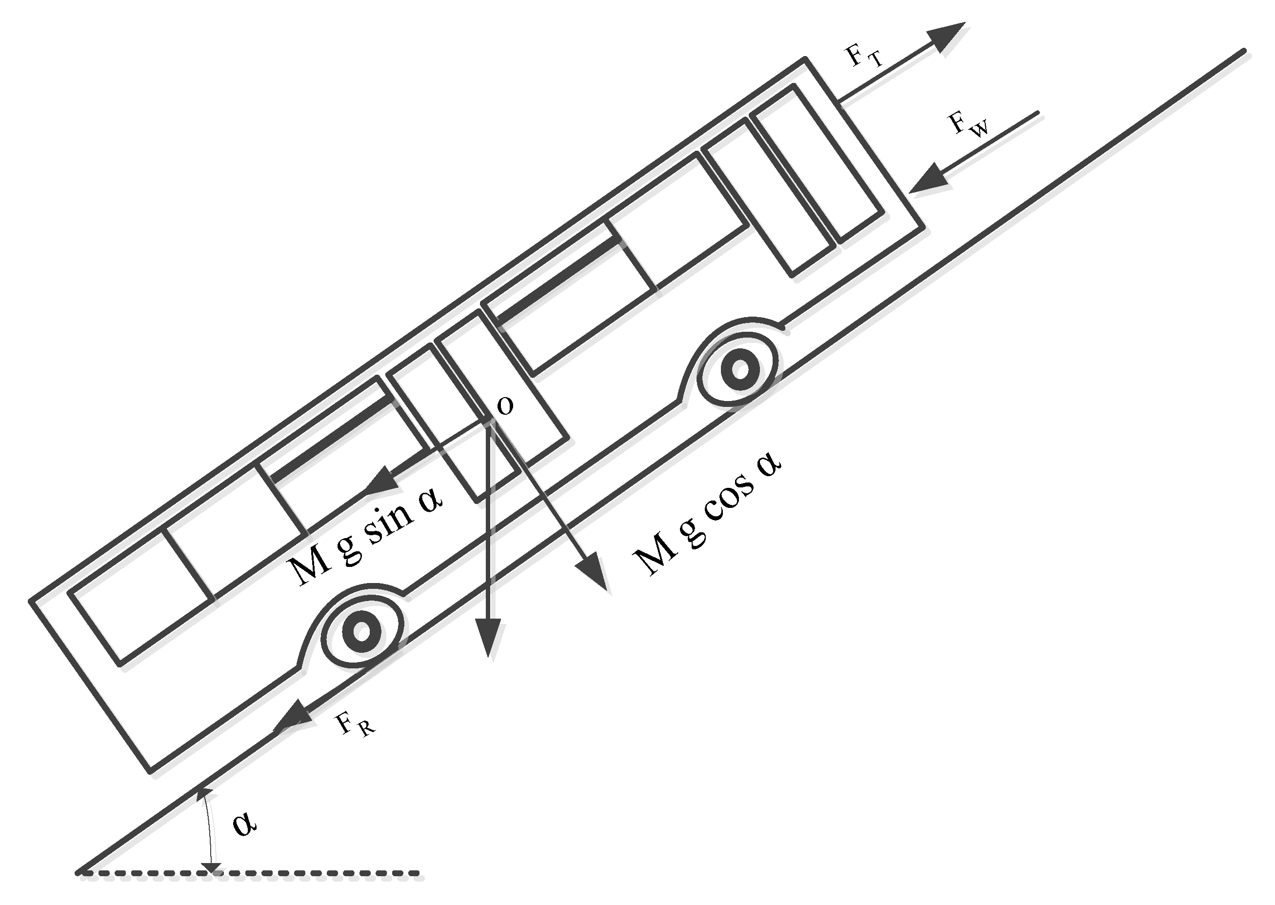
The designing of EB entail the physics fundamental concept, the Newton’s second law of motion. The EB maneuver can be wholly defined by evaluating the thrust forces applied to it in the operational direction. The different forces applied and resisting in the EB, when it is moving in an uphill direction are shown in Figure 1. There are forces which act on the EB in the uphill direction of movement and forces which resist the EB movement. The force, due to which the EB can move forward, are known as tractive force. (). There exist some opposite direction forces that are put into effect on the EB when moving on a certain land profile—the rolling resistance force (), the aerodynamic drag (), the grading or uphill force () and the acceleration force. The fundamental principle of the vehicle dynamics, expressed in [27,30], are as follows:
where, m is the mass of the EB (kg); g is the gravitational constant (m/s); is the driving velocity of the EB; is the rolling resistance; is the air density (kg/m); A is the frontal area of EB; is the coefficient of drag; is the climb angle.
The total power requested by the wheels of the EB or the total power required to propel the vehicle is expressed in the equation below:
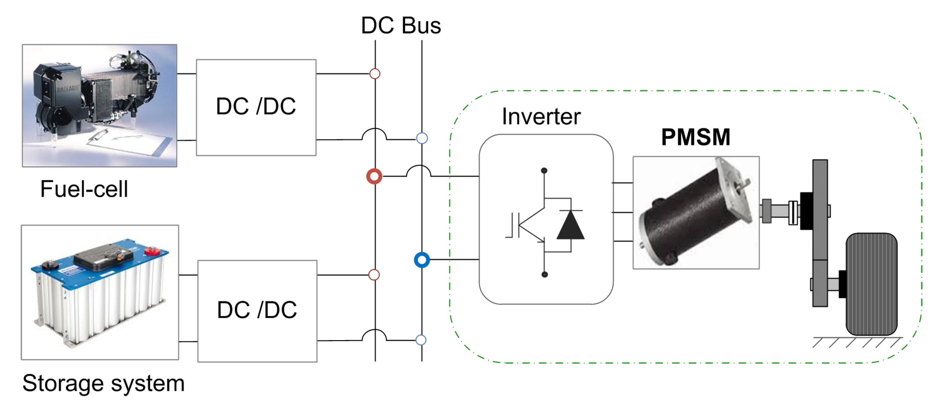
Figure 2 illustrates a typical circuit representation of an BE, wherein fuel cells (energy source) and super capacitors (power source) are connected to the common Direct current (DC) sources via DC/DC converters. While the energy source ensures the steady state operation, the power source is attached to the capacitor-link through bidirectional converter to supply the peak power demand and to keep the capacitor voltage fixed. The motor drive includes a three-phase inverter, PMSM and the coupling load. In this work, the study is focused on the drive side where the capacitor-link is supposed as a voltage source (constant) and the load effect is emulated by a DC generator.
The modeling of the PMSM expressed in the Park’s reference frame is given below:
where is the voltage of stator vector, is the current of stator vector, is the flux of stator, is the resistance of stator, is the electrical speed of rotor, p is the number of the pole pairs, the angular speed and is a coupling matrix between d and q.
The flux of stator is expressed in the equation below:
where is the inductance of stator and is the Magnetic Flux.
The electromagnetic torque can be written as in Equation (5).
The formula for motion is in Equation (6).
where is the resistance torque, is the frictional factor and J is the mechanical moment of inertia.
3. Proposed Direct Torque Controller
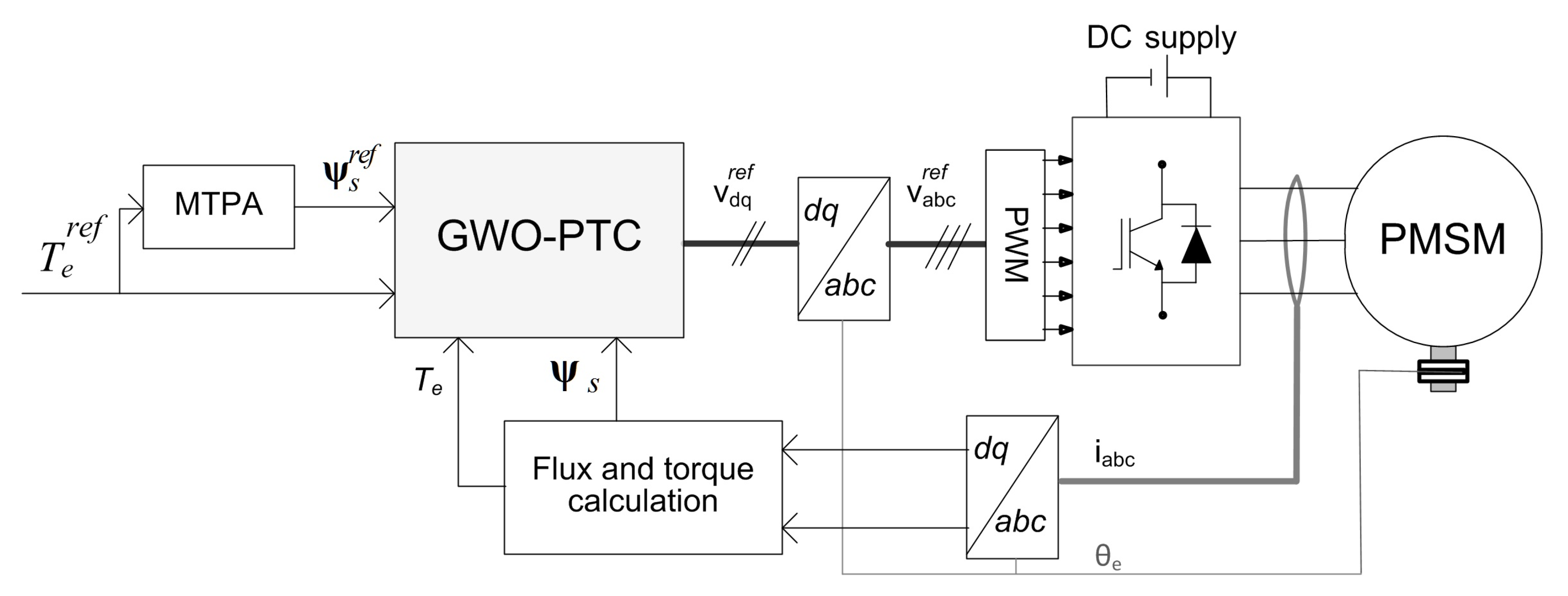
The aim of this section is to describe the plan strategy of the proposed approach based on GWO. The block diagram of the proposed torque controller strategy is illustrated in Figure 3. In this scheme, an MTPA is used to calculate the flux reference. Then, the proposed PTC-GWO controller ensures the desired tracking performances of both torque and flux with smooth-time evolution.
3.1. Maximum Torque Per Ampere (MTPA)
The torque production in a PMSM is a function of and as described in (5). The magnitude reference of the flux of stator is acquired from the torque reference. It was found that the stator flux trajectory is necessary to achieve MTPA condition [31]. The electromagnetic torque can be formulated as follows:
which can be written as in Equation (5) where is the angle among and when is neglected. In fact, using Equation (7), the stator flux can be expressed as:
The above equation appears as the stator flux component in the quadrature axis. In PMSM, because is the d-component of and the Direct component is zero, the reference of amplitude flux can be described as:
After the calculation of the MTPA there was the need to reference flux by the formula represented in Equation (9)
In this case, utilizing the reference of stator flux, we can attain a higher system efficiency.
3.2. GWO Based PTC Control
As discussed in the introduction, the use of GWO is of a growing interest because of its advantages in solving optimization problems with pulling in properties, such as quick convergence, robustness and not many adjustment gains [28]. Herein, the key is thought to require the advantage of the quick optimization process of the GWO in order to reduce the discrepancies through the estimated torque and flux and their references. In this case, GWO algorithms-based PTC acts as a controller to generate the optimal voltage vector components via fitness functions minimization. To this end, fitness functions considering flux and torque errors are defined.
where G = is the objective vector, the first fitness function is characterized by and only one control input while the second fitness function is characterized by , and is concerned with minimizing the and only one control input . are constant gains, is the sample time. , the actual values () of the tracking error are given by:
Besed on the GW theory, the construction mechanism of the GW based control algorithm involves three steps:
Step (1) The Evaluation of Hunting Resolutions:
This step consists in the choice of a candidate fitness function with the means to minimize the tracking error and torque ripples. The algorithm evaluates the whole hunting solutions following the iteration number and then the search agents are allowed to locate the plausible situation of the prey (input control). The grey wolves encompass prey amid the chase. The encompassing behavior can be scientifically modeled as takes after:
where n is the actual iteration, and are factors vectors, is the situation vector of the optimal resolution and is the situation vector of a search agent. The vectors and are expressed as:
where components of are directly diminished from 2 to agree with iterations and the value of the are in between 0 and 1
Step (2) Ideal hunting distance:
The method mechanism looks at better resolution with regard to the global hunting resolution and calculates the candidate’s voltage references. According to (Equation (13)), the first three better resolutions acquired can be submitted as follows:
where . The ideal interval vector is then used to formulate an intermediate input control variables as defined in (Equation (18)).
where , .
At last, by the utilization of the predefined middle variables, the updated candidate algorithm is determined by:
Step (3) Reference choice:
As shown inside the past part, a definitive arrangement step is contained inside the appraisal of the developed control plans in the step of ideal hunting. In this, these control arrangements are defined by their particular distances . In this manner, the voltage reference (d-axis) is chosen as follow:
The built-up candidate input of control, in ideal hunting distance, and its indicated distance are assessed (take the value of less than one ) so as to predict future reference of control.
3.3. Flux-Weakening and Torque Limitation
The running of the PMSM machine is commonly characterized into three fundamental zones—i.e., weak torque operation, fixed torque, and fixed power zones (see Figure 4). The inverter voltage restrain is regarded by diminishing the flux reference as takes after:
where vdc is the measure of DC source voltage and . It is not fundamental to know the corner speed a priori: Equation (21) adjusts the flux reference concurring to the current speed and the obtainable voltage. Current magnitude is limited to the maximum current value of inverter by constraining the torque reference
where is the amplitude reference of the stator flux reference.
4. Simulation Results
In this section, the objective function parameters are selected through simulations under Matlab/Simulink software. The proposed selection criterion is based on torque ripple reduction at steady state operation when the system is subject to non-sinusoidal flux density distribution. The system parameters are recorded in Table 1.
The corresponding torque harmonics show up as the sixth, twelfth and different products of the sixth harmonics [32,33], and can be calculated by:
where is the amplitude of harmonics (multiple sixth).
The 6th, 12th, 18th and 24th flux harmonics are induced in the torque and are chosen equally, respectively, to 7%, 3%, 2% and 1% of the rated torque (). The system parameters are given in Table 1.
In this scenario, the torque reference is set to its nominal value under a speed of 100 rpm. The parameters of the fitness function are changed consecutively and the corresponding is expressed by:
where m is the number of points and is the torque reference.
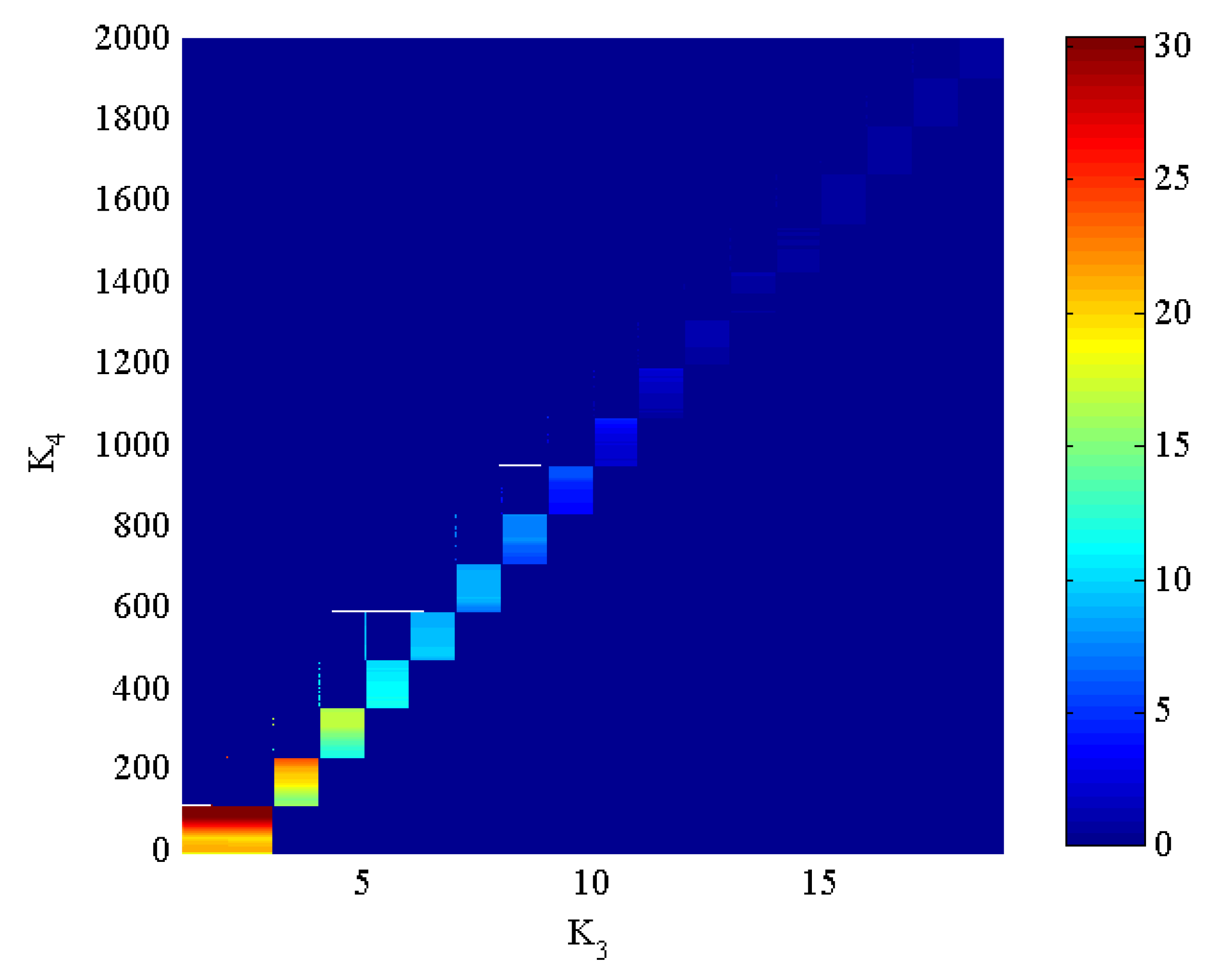
Figure 5 illustrates the influence of the parameters of the objective function on the torque ripple rate . As an indicator, with the color change from blue to red, there is an increasing influence on the torque ripple amplitude. In this test, parameters and are changed, respectively, from 0 to 20 and 0 to 2000. It very well may be seen that the torque ripple can be minimized for infinity of solutions (blue zone) and the best choice also depends on the system performance under dynamic operation.
As a result of the previous test, parameters ( and ) are directly related to the resulting torque ripple amplitude. These parameters are set to: = 11 and = 0.01 which satisfy a fast time response without overshoot under stepped torque and particularly a reduced torque ripple at steady-state operation.
Notices that parameters and of the objective function do not influence the torque ripple, which means that the control of the torque is decoupled from the flux. The gains , are set to = 1.5 and = 0.5 which ensure the flux tracking task.
To examine the impact of the parameters choice on the system execution, the following simulation tests are conducted for two parameters sets:
- -
- Case (1), by a poor choice of the parameters which are in the yellow zone of Figure 3. For this, parameters and are chosen equal to: = 7.5 and = 530.
- -
- Case (2), by considering the best objective function parameters.
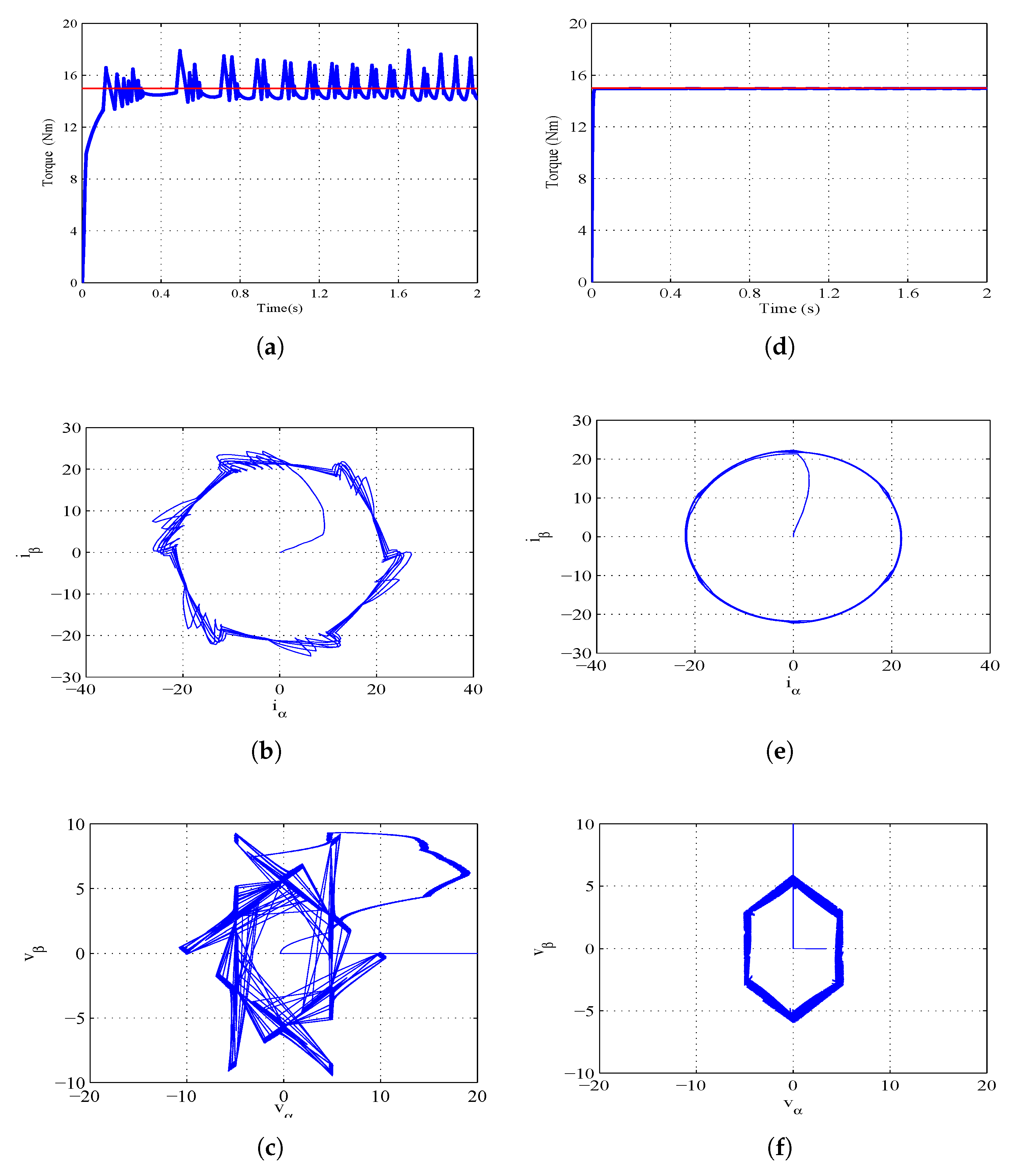
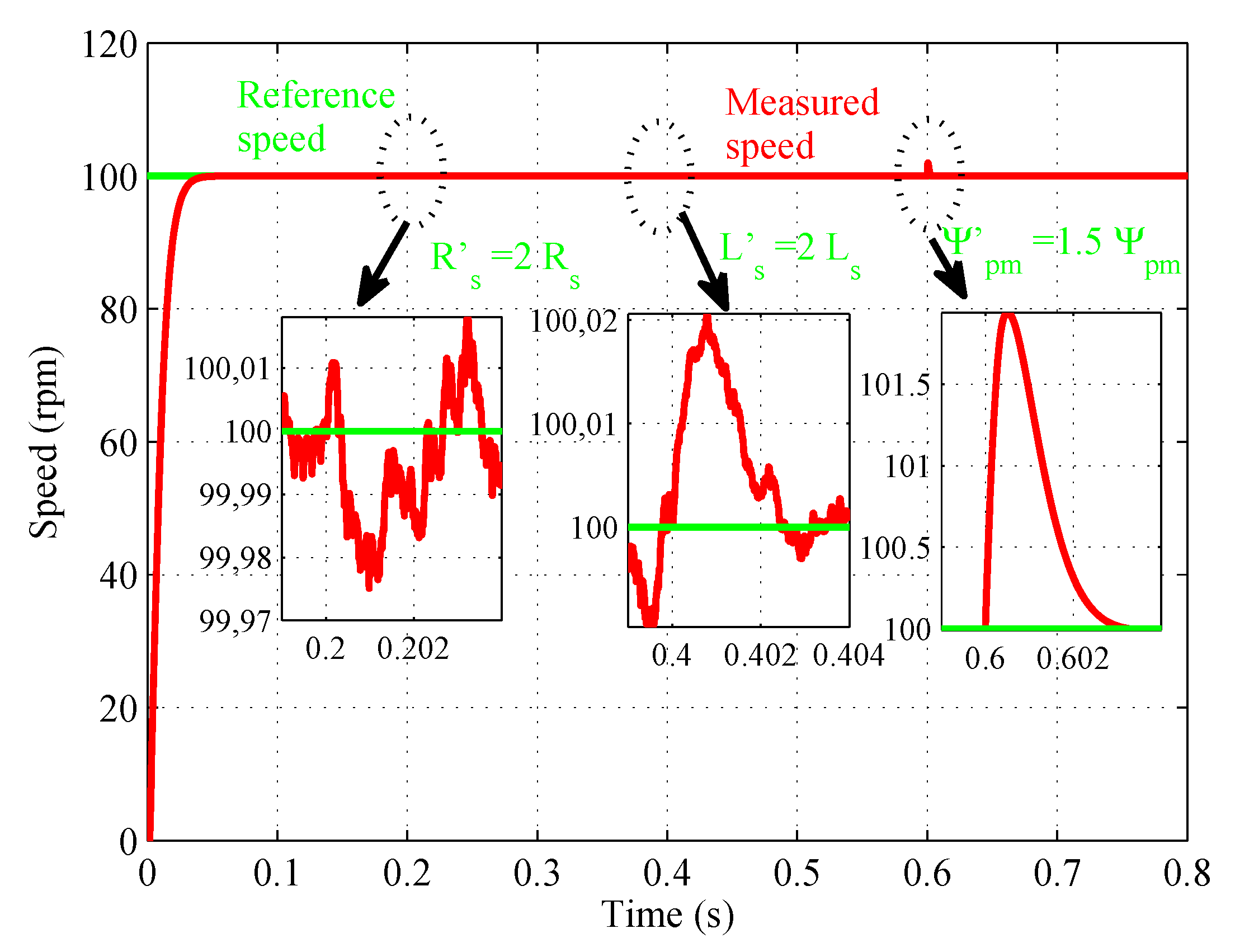
Figure 6 shows the system response under a torque reference of 15 Nm. In this test the torque response, the respective Concordia components of the stator currents, and the input control voltages are highlighted for the two considered parameters sets. Figure 6a,d illustrate that the torque response when the best objective function parameters are applied (Figure 6d) follows its reference trajectory with a smoother torque evolution. Figure 6b,e illustrate the corresponding trajectories of the stator currents in Concordia coordinates for the two considered parameter sets. With the best objective function parameters, the currents follow circular trajectories which means that the resulting current waveforms are sinusoidal. To investigate the input control behavior under the same test, Figure 6c,f show the respective trajectories of the input control voltages in Concordia coordinates. From this result, it can be seen that the GW algorithm with the best objective function parameters allows generating minimal input control trajectories and it can be noted that the control efforts are well distributed over the six sector of the PWM. Figure 7 shows the speed response in time domain at 100 rpm under parametric variations. The figure is illustrated in three sequences, respectively: [0.2 to 0.4 s] the stator resistance increase of 100%, between [0.4 to 0.6 s] the stator inductance increase of 100% and between [0.6 to 0.8 s] the stator flux increase of 50%. It is demonstrated that GWO-PTC approaches can endure large parametric variations and, at the same time, maintain good vehicle performance. It can be noticed that the GWO control design does not depend on model parameter knowledge (free-model controller).
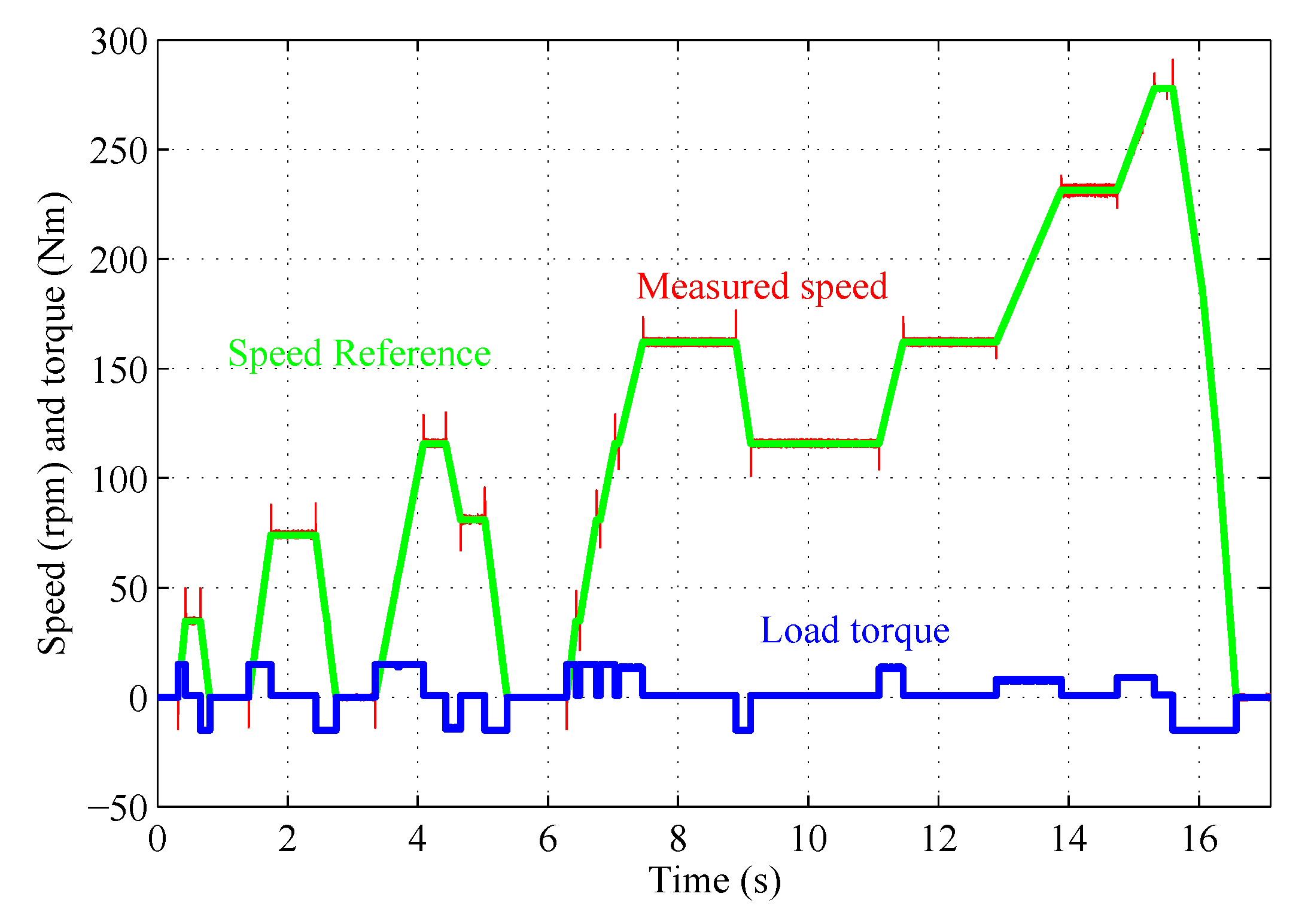
To evaluate the electric Bus dynamic performances, the bus speed and Load torque are illustrated in Figure 8. For that purpose, the speed reference changes during the proposed cycle under torque change.
5. Experimental Verification
In order to verify the viability and the effectiveness of the control scheme, tests are carried out under a dSPACE DS1103 PPC control board. The dSPACE DS1103 PPC control board is intended to meet the necessities of present-day quick control prototyping. It contains the following inputs/outputs ports: 50 bit-In/Out channels, 36 ADC, and 8 DAC. The test bench comprises of a Motor (PMSM) and a DC generator which acts as a brake. The drive and controller parameters used in these experiments are the same with those used in simulation. Note that only the best objective function parameters selected in the simulation part are considered in the following sections.
5.1. Dynamic Performance
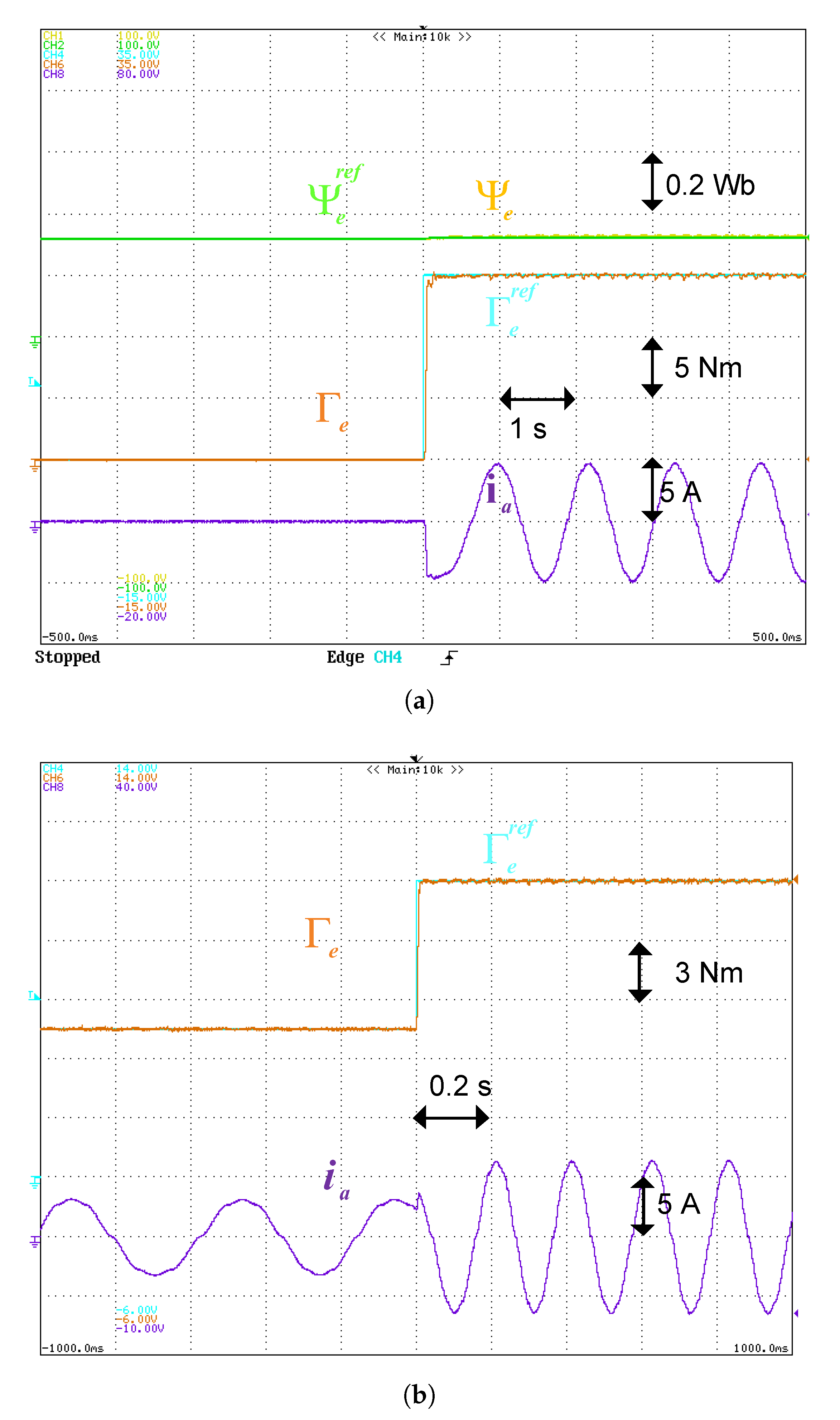
The proposed GWO-PTC is applied to study the dynamic behavior of the framework, as display in Figure 9. Figure 9a illustrates the system response at start-up. It very well may be seen that both torque and flux follow their particular references. In Figure 9b, the system response when the torque reference step change from 7.5 to 15 Nm is presented. In this test, it can be noted that the torque tracks its reference trajectory without overshoot. The time response is within 0.022 s.
5.2. Steady-State Performance
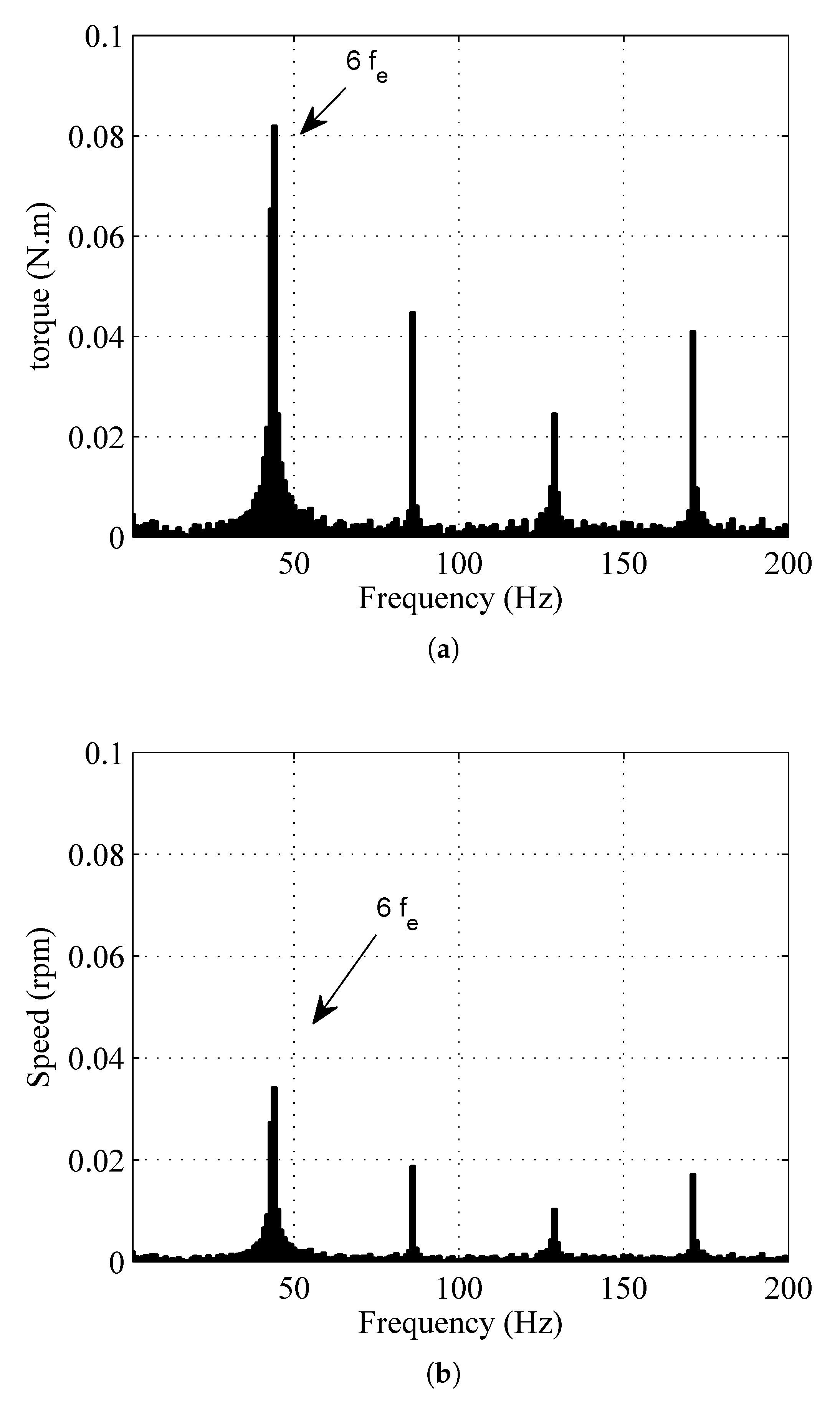
To highlight the execution of GWO-PTC on the quality of torque and speed, the harmonic issue at low speed operation is investigated. As is well known, torque harmonics (ripple) are inherent for PMSM at low speeds, and these disturbances can induce the speed ripple as well.
Figure 10a,b illustrates the frequency domains of the AC components of the torque and the speed at steady-state; when the operating conditions are a speed of 100 rpm and a torque of 15 Nm. This result illustrates the presence of particular harmonic orders, especially the sixth and multiple sixth harmonics. These harmonic orders can be linked to the non sinusoidal flux distribution in the air gap. Additionally, it can be underlined that the torque and the speed ripple rates are, respectively, within 2.7% and 0.5% of their average values.
5.3. Speed Tracking
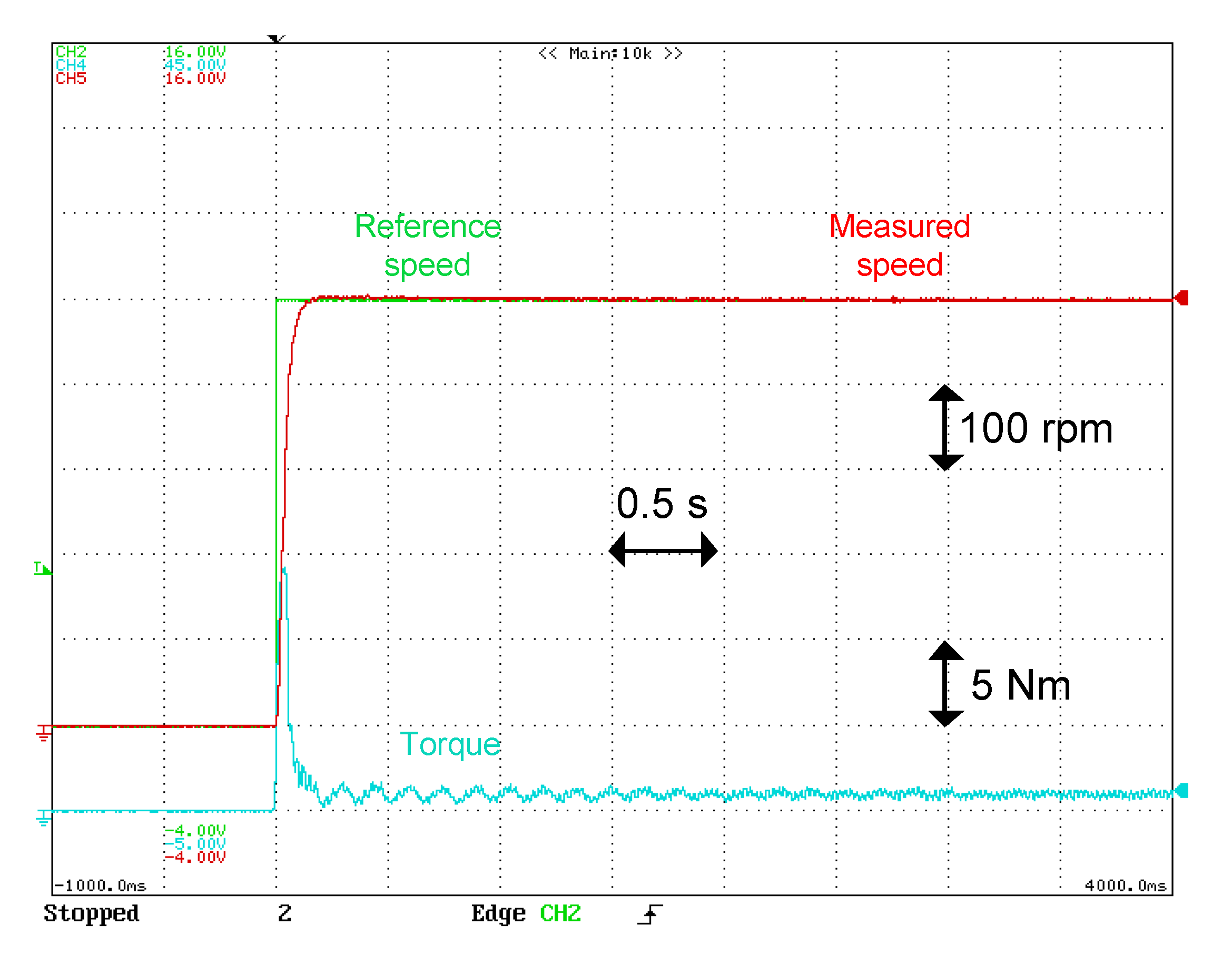
This section evaluates the performance of the proposed control when it used as an inner control loop, where the reference torque is generated by an external speed loop. The external loop (speed) is based on classical Proportional Integral (PI) regulator where the parameters gains and are calculated by and , where is the cutoff frequency of the external loop which is set to 100 rad/s.
Figure 11 illustrates the system start-up with a bus speed reference equal to 500 rpm under no load. It can be seen that the machine speed takes after its reference direction without overshoot. The settling time is about 0.2 s.
5.4. Flux Weakening
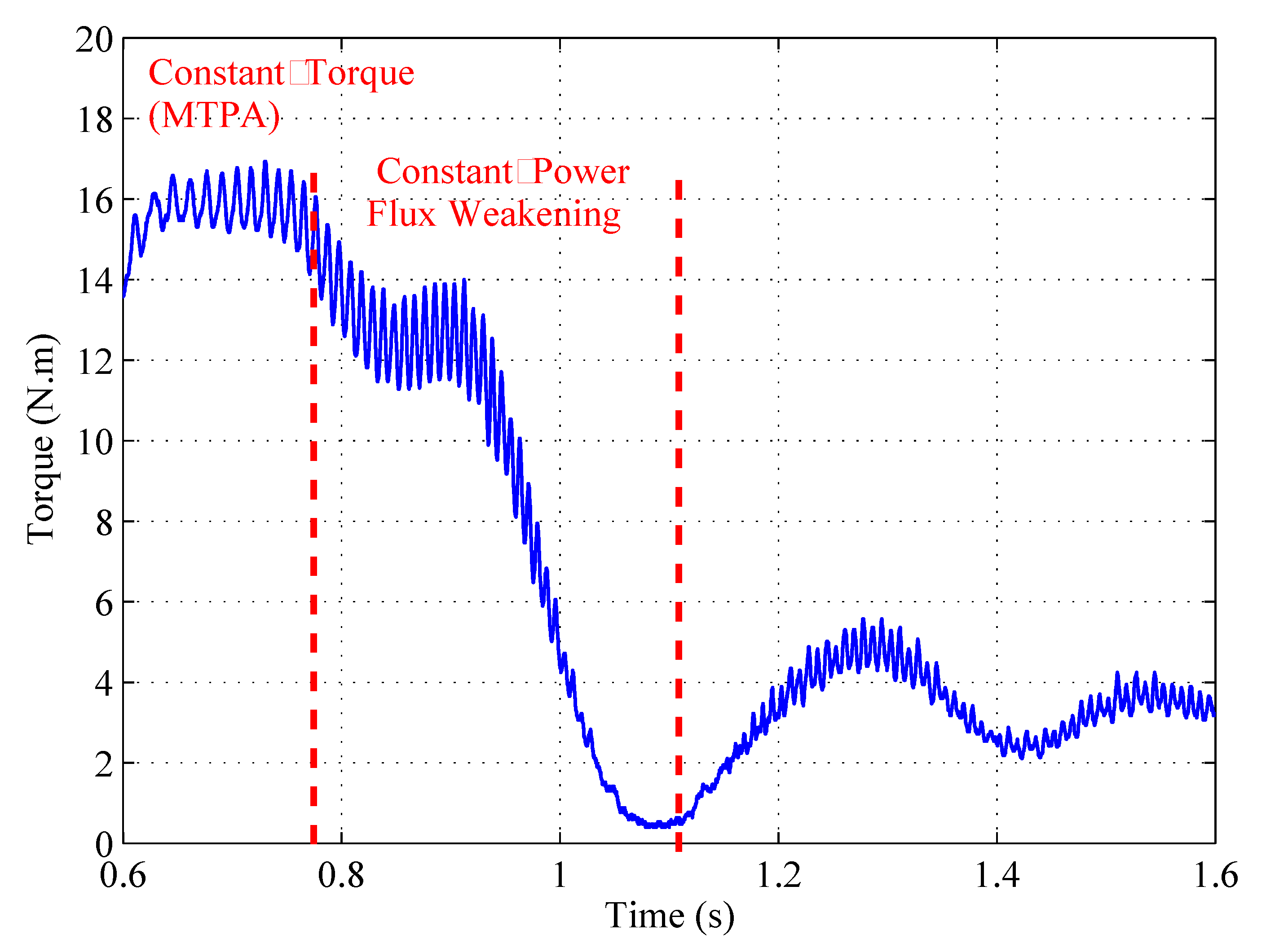
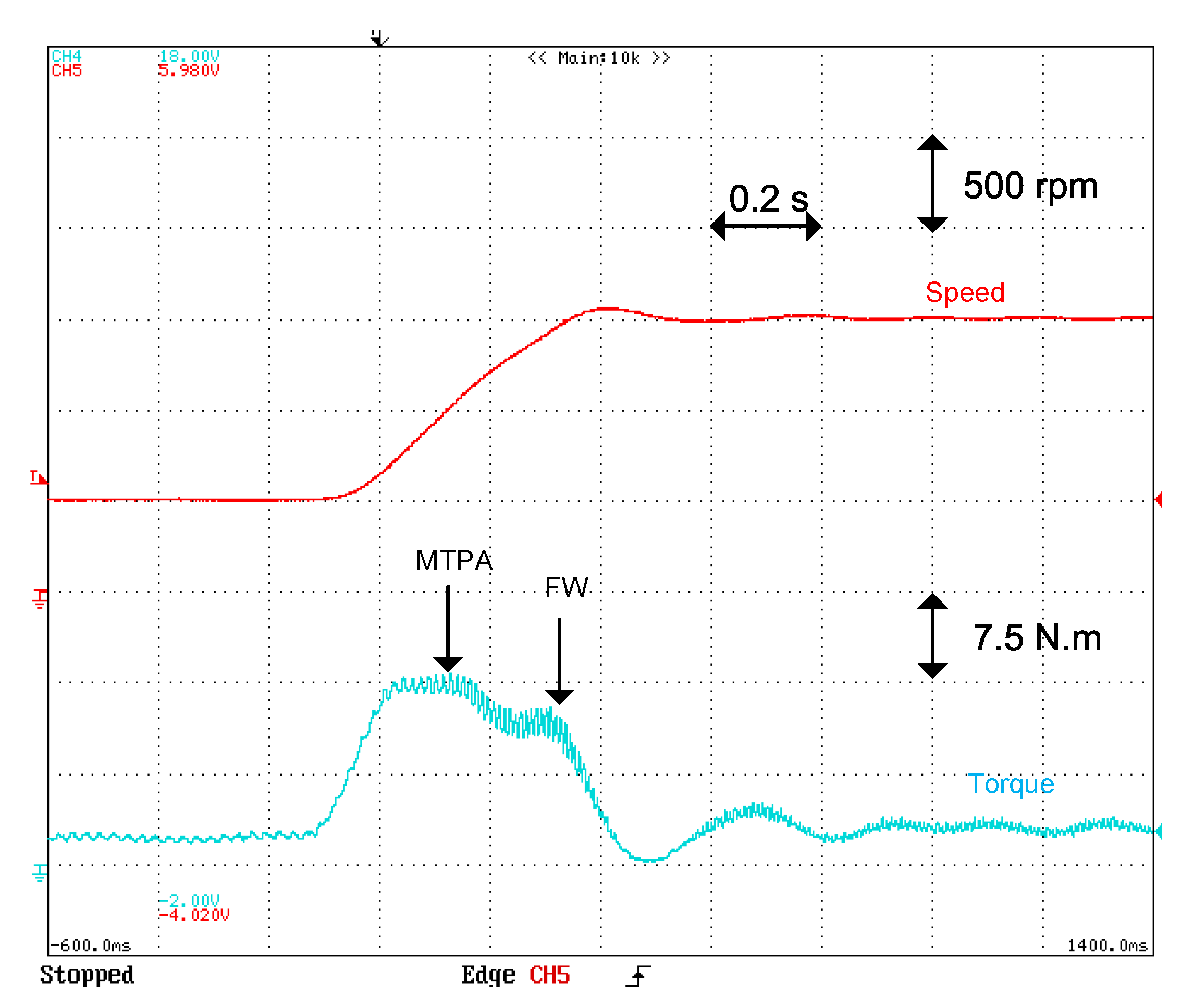
In the investigation of the dynamic performances of the Flux Weakening method, the bus speed reference modifies of 500 to 1500 rpm beneath a constant load. Figure 12 displays the wave-forms of the speed and torque reaction of the Motor. The control mode shifts from MTPA to FW at the base speed.
6. Comparison between DTC-PI and GWO Controllers for Speed Control
To highlight the advancement of the proposed strategy, a comparison with classical DTC based on a PI regulator is proposed. The design method for the DTC-PI controller is described in [27].
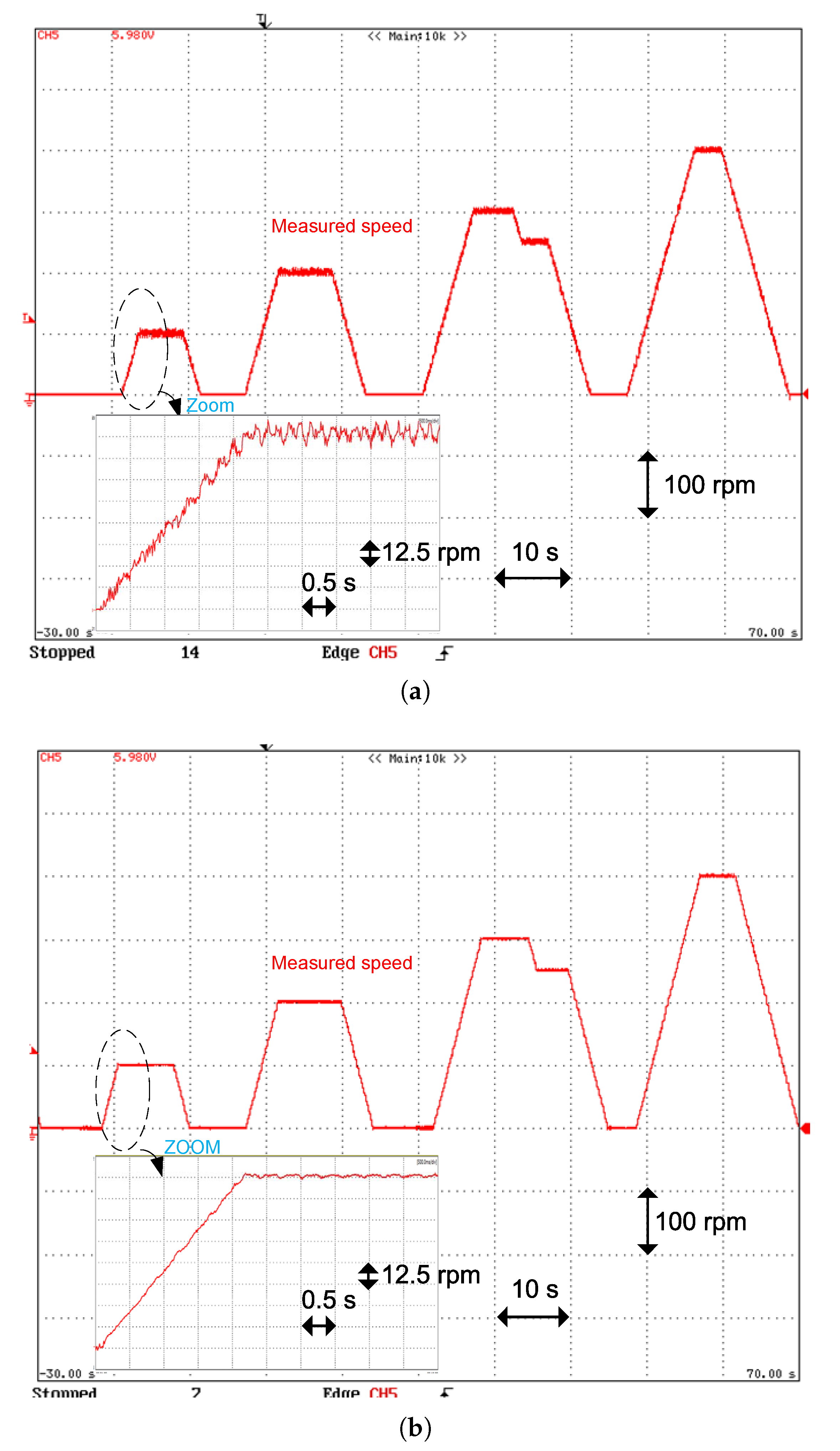
Figure 13a,b, displays the Motor behavior with a DTC-PI and the GWO strategy when the bus speed reference changes during the proposed cycle. The speed ripple factor (SRF) values of the DTC-PI and the proposed approach for diverse speed values are shown in Figure 14. From this result, the SRF evolution indicates that the proposed approach decreases the speed ripples by a factor of more than 3.75.
In summary, from the tests presented in this section, it can be stated that employing the GWO-PTC allows for obtaining a high-performance control with a smooth-time evolution of the torque and the speed. From the implementation side, the time duration for the compilation of the proposed strategy is found to utilize one of the timers of the dSPACE DS1103 PPC.
The treatment turnaround time within the ControlDesk of the complete proposed strategy counting the park transformation (currents), speed calculation (from the resolver), speed reference generator and the proposed GW controller is 46.3 s whose 39.5 s were used to implement the proposed control. In addition, the algorithm is coded in C language, and based on the available powerful control cards (DSP, FPGA, dsPIC...), the treatment time and CPU utilization is not influenced much by the execution of the proposed method.
7. Conclusions
This work of research has proposed the Grey Wolf Optimizer based Predictive Torque Control (GWO-PTC) for smooth torque operation in electric bus applications. The proposed approach invests the quick optimization process of the GWO to design an efficient predictive torque controller without requiring knowledge of the PMSM parameters. The mathematical principle of the proposed GWO-PTC controller is itemized, and the fitness function parameter selection is presented in the first part of the simulation. The carried-out experimental tests on a dSPACE 1103 control board have clearly demonstrated the feasibility and the forcefulness of the proposed control method in terms of robustness and torque tracking performance under time-varying load. The analysis of the system performance under low speed operation shows that the proposed GWO-PTC ensures smooth-time evolutions of both speed and torque. From this viewpoint, another comparison with advanced optimizer approaches are required to supply a better understanding of the PTC-GWO effectiveness algorithm under real-time working conditions.
Author Contributions
A.D. and A.H. were responsible for computational modeling and data analysis. A.D. and A.H. carried out experiments and analysis. M.M. and M.G. conceived of the study, and participated in research coordination. All authors have read and agreed to the published version of the manuscript.
Funding
This research was funded by FEDER and WISE RFI Electronique.
Acknowledgments
This paper was bolstered by the European Fund for Regional Development (FEDER) and WISE RFI Electronique.
Conflicts of Interest
The authors announce no conflict of interest.
References
- Pamuła, T.; Pamuła, W. Estimation of the Energy Consumption of Battery Electric Buses for Public Transport Networks Using Real-World Data and Deep Learning. Energies 2020, 13, 2340. [Google Scholar]
- Xia, C.; Ji, B.; Yan, Y. Smooth speed control for low-speed synchronous motor using proportional integral resonant controlle. IEEE Trans. Ind. Electron. 2014, 62, 2123–2134. [Google Scholar]
- Saito, N.; Kijima, R.; Shimomura, S. The design method to minimize torque ripple in interior permanent magnet synchronous motor with concentrated winding. IEEE Trans. Ind. Electron. 2010, 45, 1293–1298. [Google Scholar]
- Güemes, J.A.; Iraolagoitia, A.M.; Del Hoyo, J.I.; Fernandez, P. Torque analysis in permanent-magnet synchronous motors: A comparative study. In Proceedings of the 2010 International Power Electronics Conference—ECCE ASIA, Sapporo, Japan, 21–24 June 2010. [Google Scholar]
- Lee, J.H.; Kim, J.W.; Song, J.Y.; Kim, Y.J.; Jung, S.Y. A Novel Memetic Algorithm Using Modified Particle Swarm Optimization and Mesh Adaptive Direct Search for PMSM Design. IEEE Trans. Magn. 2015, 52, 1–4. [Google Scholar] [CrossRef]
- Feng, G.; Lai, C.; Kar, N.C. Practical Testing Solutions to Optimal Stator Harmonic Current Design for PMSM Torque Ripple Minimization Using Speed Harmonics. IEEE Trans. Power Electron. 2017, 33, 5181–5191. [Google Scholar] [CrossRef]
- Zhu, H.; Xiao, X.; Li, Y. Torque ripple reduction in the torque predictive control scheme for permanent-magnet synchronous motors. IEEE Trans. Ind. Electron. 2012, 59, 871–877. [Google Scholar] [CrossRef]
- Cho, Y.; Lee, K.B.; Song, J.H.; Lee, Y.I. Synchronous Motor With Concentrated Winding. IEEE Trans. Ind. Electron. 2010, 45, 235–248. [Google Scholar]
- Lai, C.; Feng, G.; Mukherjee, K.; Kar, N.C. Investigations of the Influence of PMSM Parameter Variations in Optimal Stator Current Design for Torque Ripple Minimization. IEEE Trans. Energy Convers. 2017, 32, 1052–1062. [Google Scholar] [CrossRef]
- Houari, A.; Bouabdallah, A.; Djerioui, A.; Machmoum, M.; Auger, F.; Darkawi, A.; Olivier, J.C.; Benkhoris, M.F. An Effective Compensation Technique for Speed Smoothness at Low-Speed Operation of PMSM Drives. IEEE Trans. Ind. Appl. 2018, 54, 647–655. [Google Scholar] [CrossRef]
- Zhang, Y.; Zhu, J. Direct torque control of Permanent-magnet synchronous motor with reduced torque ripple and commutation frequency. IEEE Trans. Power Electron. 2011, 26, 235–248. [Google Scholar]
- Xia, C.; Zhao, J.; Yan, Y.; Shi, T. A novel direct torque and flux control method of matrix converter-fed PMSM drives. IEEE Trans. Power Electron. 2013, 29, 5417–5430. [Google Scholar] [CrossRef]
- Chai, S.; Wang, L.; Rogers, E. A cascade MPC control structure for a PMSM with speed ripple minimization. IEEE Trans. Power Electron. 2013, 60, 2978–2987. [Google Scholar] [CrossRef] [Green Version]
- Vafaie, M.; Dehkordi, B.; Moallem, P.; Kiyoumarsi, A. Minimizing Torque and Flux Ripples and Improving Dynamic Response of PMSM using a Voltage Vector with Optimal Parameters. IEEE Trans. Ind. Electron. 2015, 63, 3876–3888. [Google Scholar] [CrossRef]
- Jezernik, K.; Korelič, J.; Horvat, R. PMSM sliding mode FPGA based control for torque ripple reduction. IEEE Trans. Power Electron. 2012, 28, 3549–3556. [Google Scholar] [CrossRef]
- Zhang, Y.; Gao, S. Simultaneous optimisation of voltage vector and duty cycle in model predictive torque control of PMSM drives. In Proceedings of the 2014 17th International Conference on Electrical Machines and Systems (ICEMS), Hangzhou, China, 22–25 October 2014; pp. 3338–3344. [Google Scholar]
- Qian, W.; Panda, S.K.; Xu, J.X. Speed ripple minimization in PM synchronous motor using iterative learning control. IEEE Trans. Energy Convers. 2005, 20, 53–61. [Google Scholar] [CrossRef]
- Niu, F.; Wang, B.; Babel, A.S.; Li, K.; Strangas, E.G. Comparative Evalution of direct torque control strategies of Permanent-magnet synchronous motor. IEEE Trans. Power Electron. 2016, 31, 1408–1424. [Google Scholar]
- Pajchrowski, T.; Zawirski, K.; Nowopolski, K. Neural Speed Controller Trained Online by Means of Modified RPROP Algorithm. IEEE Trans. Ind. Inform. 2015, 11, 560–568. [Google Scholar] [CrossRef]
- Ma, Z.; Saeidi, S. FPGA Implementation of Model Predictive Control With Constant Switching Frequency for PMSM Drives. IEEE Trans. Ind. Electron. 2014, 10, 2055–2063. [Google Scholar] [CrossRef]
- Cimini, G.; Bernardini, D.; Bemporad, A.; Levijoki, S. Online model predictive torque control for permanent magnet synchronous motors. In Proceedings of the 2015 IEEE International Conference on Industrial Technology, Seville, Spain, 17–19 March 2015. [Google Scholar]
- Mirjalili, S.; Mirjalili, S.M.; Lewis, A.; Optimizer, G.W. Advances in Engineering Software Grey Wolf Optimizer. Adv. Eng. Softw. 2014, 69, 46–61. [Google Scholar]
- Mirjalili, S.; Saremi, S.; Mirjalili, S.M.; Coelho, L.D.S. Multi-objective grey wolfoptimizer: A novel algorithm for multi-criterion optimization. Expert Syst. Appl. 2016, 47, 106–119. [Google Scholar]
- Djerioui, A.; Houari, A.; Ait-Ahmed, M.; Benkhoris, M.F.; Chouder, A.; Machmoum, M. Grey Wolf based control speed ripple reduction at low speed operation of PMSM drives. ISA Trans. 2018, 74, 111–119. [Google Scholar] [CrossRef]
- Sultana, U.; Khairuddin, A.B.; Mokhtar, A.S.; Zareen, N.; Sultana, B. Grey wolf optimizer based placement and sizing of multiple distributed generation in the distribution system. Energy 2016, 111, 525–536. [Google Scholar] [CrossRef]
- Precup, R.-E.; David, R.-C.; Petriu, E.M. Grey wolf optimsation optimal sizing of battery energy storage device to minimise operation cost of microgrid. IET Gener. Transm. Distrib. 2016, 10, 625–637. [Google Scholar]
- Tabbache, B.; Benbouzid, M.E.H.; Kheloui, A.; Bourgeot, J.M. Virtual-Sensor-Based Maximum-Likelihood Voting Approach for Fault-Tolerant Control of Electric Vehicle Powertrains. IEEE Trans Veh. Technol. 2013, 62, 1075–1083. [Google Scholar] [CrossRef] [Green Version]
- Djerioui, A.; Houari, A.; Saim, A.; Ait-Ahmed, M.; Pierfederici, S.; Benkhoris, M.F.; Machmoum, M.; Ghanes, M. Flatness Based Grey Wolf Control for Load Voltage Unbalance Mitigation in Three-Phase Four-Leg Voltage Source Inverters. IEEE Trans. Ind. Appl. 2019, 56, 1869–1881. [Google Scholar] [CrossRef]
- Rothgang, S.; Rogge, M.; Becker, J. Battery Design for Successful Electrification in Public Transport. Energies 2015, 8, 6715–6737. [Google Scholar] [CrossRef] [Green Version]
- Cho, Y.; Lee, K.B.; Song, J.H.; Lee, Y.I. Torque ripple minimization and fast dynamic scheme for torque predictive control of permanent-magnet synchronous motors. IEEE Trans. Power Elect. 2015, 30, 2182–2190. [Google Scholar] [CrossRef]
- Xiao, X.; Chen, C. Reduction of torque ripple due to demagnetization in PMSM using current compensation. IEEE Trans. Appl. Supercond. 2010, 20, 1068–1071. [Google Scholar] [CrossRef]
- Yuan, Y.; Auger, F.; Loron, L.; Moisy, S.; Hubert, M. Torque ripple reduction in Permanent Magnet Synchronous Machines using angle based iterative learning control. In Proceedings of the IECON 2012—38th Annual Conference on IEEE Industrial Electronics Society, Montreal, QC, Canada, 25–28 October 2012. [Google Scholar]
- Houari, A.; Auger, F.; Olivier, J.-C.; Machmoum, M. A New Compensation Technique for PMSM Torque Ripple Minimization. In Proceedings of the IEEE Industry Applications Society Annual Meeting Industry Applications Society Annual Meeting, Dallas, TX, USA, 18–22 October 2015; pp. 1–6. [Google Scholar]
Figure 1.
EB moving uphill and forces opposing the movement.

Figure 2.
Typical power topology of an electrical vehicle based on PMSM drive.

Figure 3.
Schematic diagram of the proposed GWO-PTC controller.

Figure 4.
Transient characteristics of control system.

Figure 5.
Impact of the fitness function parameters on the .

Figure 6.
Simulations results: system response under a torque reference of 15 Nm for the two considered parameters sets, with: (a) and (d) torque; (b) and (e) trajectories of the stator currents in Concordia coordinates; (c) and (f) trajectories of the input control voltages in Concordia coordinates.

Figure 7.
Speed reponse with parameters variations.

Figure 8.
Speed Reference, Measured speed and absolute load torque over the proposed cycle.

Figure 9.
Experimental plots: torque tracking performance for the following tests: (a) start-up (0 to 15 Nm); (b) reference torque step (7.5 Nm to 15 Nm).
Figure 9.
Experimental plots: torque tracking performance for the following tests: (a) start-up (0 to 15 Nm); (b) reference torque step (7.5 Nm to 15 Nm).

Figure 10.
Harmonic spectra (experimental data) under 15 Nm torque and 100 rpm speed with: (a) the torque; (b) the speed.
Figure 10.
Harmonic spectra (experimental data) under 15 Nm torque and 100 rpm speed with: (a) the torque; (b) the speed.

Figure 11.
Experimental plots: speed and torque responses at the startup (0 to 500 rpm).

Figure 12.
Dynamic responses of the GWO drive, incorporating control trajectories under constant torque operation.
Figure 12.
Dynamic responses of the GWO drive, incorporating control trajectories under constant torque operation.

Figure 13.
Experimental plots: Bus speed during the proposed cycle: (a) classical DTC method based on a PI control, (b) the proposed controller.
Figure 13.
Experimental plots: Bus speed during the proposed cycle: (a) classical DTC method based on a PI control, (b) the proposed controller.

Figure 14.
Evolution of the SRF at different speeds.


Table 1.
PMSM Parameters
| Parameters | Value |
|---|---|
| 0.25 | |
| 4.8 mH | |
| P | 4 |
| 0.32 Wb | |
| J | 0.00774 kg/m |
| 1500 rpm | |
| 16.67 Nm |
© 2020 by the authors. Licensee MDPI, Basel, Switzerland. This article is an open access article distributed under the terms and conditions of the Creative Commons Attribution (CC BY) license (http://creativecommons.org/licenses/by/4.0/).
Share and Cite
MDPI and ACS Style
Djerioui, A.; Houari, A.; Machmoum, M.; Ghanes, M. Grey Wolf Optimizer-Based Predictive Torque Control for Electric Buses Applications. Energies 2020, 13, 5013. https://doi.org/10.3390/en13195013
AMA Style
Djerioui A, Houari A, Machmoum M, Ghanes M. Grey Wolf Optimizer-Based Predictive Torque Control for Electric Buses Applications. Energies. 2020; 13(19):5013. https://doi.org/10.3390/en13195013
Chicago/Turabian StyleDjerioui, Ali, Azeddine Houari, Mohamed Machmoum, and Malek Ghanes. 2020. "Grey Wolf Optimizer-Based Predictive Torque Control for Electric Buses Applications" Energies 13, no. 19: 5013. https://doi.org/10.3390/en13195013
Note that from the first issue of 2016, this journal uses article numbers instead of page numbers. See further details here.