Field Oriented Control-Based Reduction of the Vibration and Power Consumption of a Blood Pump


School of Engineering and Built Environment, Griffith University, Queensland 4222, Australia
*
Author to whom correspondence should be addressed.
Energies 2020, 13(15), 3907; https://doi.org/10.3390/en13153907
Submission received: 6 June 2020
/
Revised: 20 July 2020
/
Accepted: 28 July 2020
/
Published: 30 July 2020
Abstract
:Power quality and energy efficiency are of great importance in motor control. The motor of any medical device needs to have a smooth torque and minimal vibration in order to maximise its energy efficiency and patient comfort. Furthermore, in rotary blood pumps, excessive energy wasted due to vibration is converted into uncontrolled movement of the mechanical parts and thus could reduce the life of the motor-pump. Besides mechanical or hydraulic origin, one of the causes of vibration in any pump is torque ripple resulting from motor phase commutation. In this paper, using relevant equipment, two extreme scenarios were examined for vibration and electrical efficiency comparison due to power quality in a blood pump: one trapezoidal control with a trapezoidal phase current output; the other a field oriented control (FOC) with a non-distorted sinusoidal phase current. The test motor-pump was the Arteriovenous Fistula Eligibility (AFE) System that is used prior to haemodialysis. The trapezoidal technique was implemented utilising the Allegro a4941 fan driver (Allegro Microsystem, 2012), and the FOC technique was implemented using the Texas Instrument digital signal processor (TMS320F28335). The aim was to reduce the energy wasted over vibration, and to achieve smooth operation of the AFE System. Vibration was measured with a one-axis accelerometer; results showed considerably lower vibration due to less current ripple associated with the FOC control as well as lower power consumption.
1. Introduction
In medical applications, particularly in wearable medical devices, a motor must function with smooth torque and minimal fluctuation over its operational speed range in order to maximise efficiency and patient comfort by reducing motor vibration and acoustic noise. Higher vibrations can decrease the pump lifetime due to imposing a cyclic-load to the mechanical structure of the pump, and can also damage bearings [1]. Vibration of a blood pump may also increase haemolysis (destruction of red blood cells) due to shear stress [2].
Vibration that exists in a motor may be due to (i) hydraulic sources (such as operating away from the best efficiency point and flow turbulence [3]); (ii) the mechanical sources (such as unbalanced impeller, bent shaft, eccentricity, cogging torque, and electro motive force (EMF) waveform imperfections [4,5,6]); or (iii) torque ripple resulting from ineffective motor commutation [7,8]. Motor commutation involves switching currents in the motor phases to develop motion and maximise torque. Besides the design and point of operation, the choice of motor commutation is a critical factor in the quality of operation of a motor, and could be a source for electromagnetic torque ripple (the periodic change of output torque) [9,10].
Previous studies of vibration of the motors used in pumps have mainly considered vibration for diagnostic reasons and as a result of mechanical deficiencies: to detect cavitation [11], in blood pumps as a measure to detect formation of thrombosis [12], and to test performance of a heart assist device [13]. Y. Li et al. [6] studied the effect of air gap deformation on electromagnetic torque and vibration resulting from that. However, it is important to separate the power-quality based vibration from mechanical sources for those diagnostic purposes. No study has previously examined the role of motor commutation system as a source of vibration in permanent magnet synchronous motors (PMSMs) or blood pumps. Pablo Donolo et al. [14] have presented laboratory test data on vibration of a PMSM motor due to voltage unbalance and distortion on an induction motor vibration. In their study, they introduced an intentionally distorted voltage to their test motor. The importance of their study was to present laboratory data and additionally compare vibration levels to the available standards. In [14], a distorted voltage was intentionally supplied to an induction motor (IM), and it was found that the sixth harmonic in vibration’s power spectrum density (PSD) of the motor was related to this voltage distortion. In addition, the same study found that the second harmonic was related to unbalance in voltage. The power quality effect from two commutation techniques on a PMSM motor and major harmonics present in the vibration spectrum will be examined in the current paper. This paper studies the vibration and power consumption improvement of the AFE System motor with a field oriented control (FOC) instead of its current trapezoidal controller based on the power quality improvement. There are also some studies about the advantages of the FOC technique [15,16,17] and torque ripple resulting from trapezoidal control [18,19], however vibration as a measure has not been considered nor the two techniques compared for a PMSM motor control. These studies have taken the modelling and theoretical approaches, instead of the experimental approach. None of the previous studies has considered this comparison of the two different motor commutation techniques, in a real scenario, on a PMSM motor, considering motor vibration and power consumption.
Therefore, the contribution of this current work is its experimental comparison of the two controllers from two applied approaches: vibration and power consumption.
In this paper, the performance of a prototype sensorless field oriented controller has been compared with the currently used AFE System sensorless trapezoidal controller, from a vibration and a power consumption point of view. Power spectral density (PSD) was used to show the vibration energy at different frequencies, and the overall power spectrum density was used to show the overall vibration change with speed. For vibrations expressed in m/s2 in time domain (), its frequency spectrum would be m/s2/Hz, and therefore its one-sided power spectrum density is (m/s2)2/Hz (which is referred to as G2/Hz in this study):
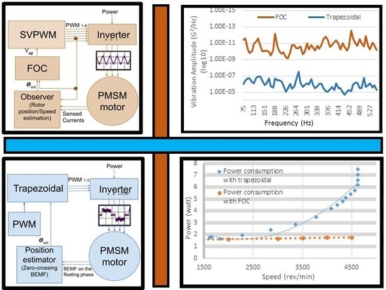
Brushless motors are commutated electronically with scalar or vector control. Trapezoidal commutation is an easy to implement scalar control in which a six stepped commutation pattern results in an inherent torque ripple (and also noise and vibration) due to inaccuracy in detection of the rotor position [20]. Field oriented control [21,22] is a high performance vector control with a complicated structure and many parameters that require tuning [23]. This technique allows time-independent control of the stator currents regardless of rotor speed and allows high performance at higher speeds. Implementation of FOC control requires deep knowledge of the technique and the motor specification, and its theory and implementation are discussed in this paper in Section 1.2 and Section 2, respectively.
In the FOC control, a sinusoidal stator current space vector (orthogonal to the rotor field) results in a smooth torque (less vibration) in a PMSM motor due to the synchronisation of the phase current and the motor’s back electro motive force (BEMF), both being sinusoidal.
Torque (and thus torque ripple) in a PMSM is directly related to back electro motive force (BEMF) in each phase and also to electrical current (Equation (1)) and will be constant if the current and BEMF follow the same trends (and harmonics) [7,24]. Due to the sinusoidal BEMF voltage of a PMSM motor, less torque ripple, and thus less vibration, is achieved when the current space vector waveform, determined by the commutation technique, is sinusoidal and rotates synchronously with the BEMF waveform on the stator windings [7,25].
where is electromagnetic torque (equal to the mutual torque when cogging and reluctance torques are zero), is the mutual torque, is the electrical current, is the BEMF voltage, and is rotational speed.
Thus, it was anticipated that vector control could improve the AFE System motor vibration due to its greater compatibility with the sinusoidal induced BEMF, and its implementation would ameliorate the inherent torque ripple that results from six-step trapezoidal commutation and gives better performance at higher speeds. It was expected that the AFE System would also run more efficiently with vector control because it avoids the higher harmonics in the current waveform seen in trapezoidal commutation. These higher harmonics do not contribute to air gap flux linkage, thus resulting in less torque, as there are no corresponding equivalents in the BEMF waveform.
This paper discusses the theoretical aspect of FOC control and sensorless estimation of rotor position. Sensorless estimation of rotor position involves not using any physical rotor position sensors, which increases system reliability and reduces maintenance costs. Furthermore, the AFE System utilises an integrated motor in a pump, which limits the use of any physical position sensor due to a limited access to the shaft of the motor. The algorithms and experimental set-ups of the sensorless trapezoidal control and FOC control of the AFE System motor is presented using a4941 sensorless trapezoidal control (Allegro Microsystem, 2012) and InstaSPIN FOC (Texas Instrument, Dallas, TX, USA) field oriented control. Following this, a comparison of the vibration and efficiency of the two different control strategies (trapezoidal control and field oriented control) is presented for a blood pump that is incorporated into the Arteriovenous Fistula Eligibility (AFE) System (Flow Forward Medical Inc., Fairway, KS, USA). The comparison was performed based on data obtained from a number of experiments. The aim was to lower the amount of wasted energy from vibration and to improve patient comfort by minimising the AFE System motor vibration, as well as to maximise device functionality through an extended speed range.
1.1. The Arteriovenous Fistula Eligibility (AFE) System
The Arteriovenous Fistula Eligibility (AFE) System is currently being trialled in a procedure to be used prior to haemodialysis which is commonly utilised in treating kidney failure patients [26]. The AFE System is aimed at increasing a patient’s eligibility for the arteriovenous fistula (AVF) procedure by sufficiently dilating veins prior to AVF creation. Figure 1 illustrates the AFE System; more details about the device and the dilation procedure are given in [26]. At the time of writing, the AFE System has successfully demonstrated rapid dilation of the cephalic in a series of pre-clinical studies, with a doubling of vein diameter from the start to the end of treatment, and is moving forward with a first-in-human (FIH) feasibility clinical trial.
This device utilises a PMSM integrated with a centrifugal blood pump. The main active element of the AFE system is an integrated motor-pump unit wherein the impeller of the motor acts as the rotor of the motor and has pin bearings to locate it within the pump housing. The motor of this device is the object of this study.
1.2. Mathematical Model of a PMSM Motor
The nonlinear dynamic model of a PMSM motor in the frame is expressed as (3) [27].
where is the stator current in the frame (stator frame), is the stator voltage in frame, is the inductance, and is the flux amplitude.
The nonlinear dynamic model of a PMSM motor in the rotor frame is expressed in (4) and (5):
where and are the direct and quadrature currents in the rotor frame, and are the direct and quadrature components of the stator voltage in the rotor frame, is winding resistance, is the direct or quadrature inductance (equal in non-salient motors like the AFE System), p is the number of pole pairs, and is the rotor angular velocity.
1.3. The Theory of Sensorless FOC Control
FOC allows the transformation of the time-varying model of a three phase motor into a DC model for independent control of torque (speed) and flux, to simplify the control algorithm. This is achieved through two mathematical transformations: Clarke transform, Park transform (and inverse Park transform). Rotor position information is required in the mathematical transformations, and in the model considered in this study is estimated through BEMF estimation. The BEMF is estimated by an observer which utilises a mathematical model based on the resistance-inductance model of a PMSM motor. Another output of the rotor position observer is an estimated speed which is then compared and regulated with a PI speed controller to generate the command signal. The other PI controller regulates the current, related to flux. Based on the command signal and inverse of the mathematical transformations, a reference voltage is generated for the pulse width modulation (PWM) converter. In the model considered in this study, space vector pulse width modulation (SVPWM) defines the switching algorithm of the inverter to determine the three phase stator voltages. The input voltage of the SVPWM converter is determined by the FOC algorithm based on the estimated rotor position and reference quadrature current signal determined by the speed PI controller.
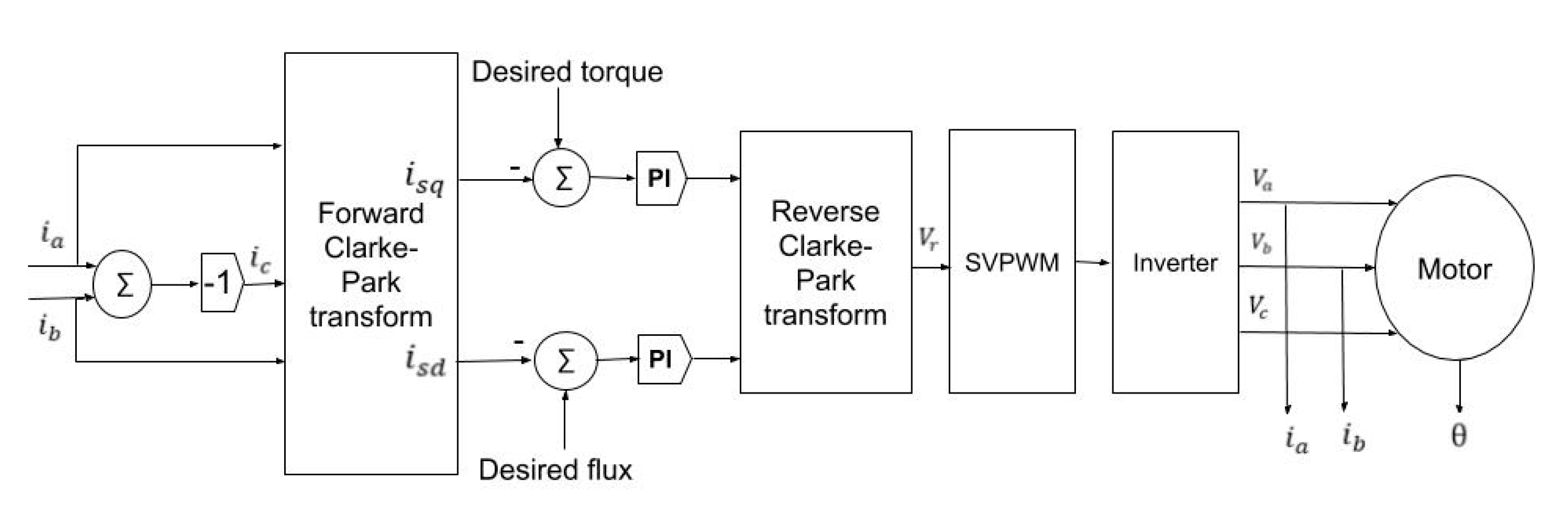
Figure 2 illustrates a standard structure schematic of FOC, which generally contains transformations (forward and reverse); torque and current controllers; an inverter; space vector modulation (SVM) and PWM generator (together, SVPWM block); phase current sensors; a rotor position feedback (sensorless observer).
The Clarke transform projects the three-phase time variant system () into the two-coordinate time variant system (α, β) and the Park transform projects the two-coordinate time variant system (α, β) into the two-coordinate time invariant system (), or the rotating rotor reference frame. This transformation will decouple the quadrature component of the stator current vector from its direct component for control of torque independently of magnetic flux in a linear and time-invariant space known as space.
The vector diagrams for the Clarke and Park transforms are illustrated in Figure 3, where:
where is the stator current vector; , , and represent phase , , and c current vectors; is the projection of to the α axis; is the current vector β component; is the flux component; is the torque component; is the rotor position.
Since magnets generate flux in permanent magnet motors, can be used for field weakening in high speed applications, or otherwise set to zero (as in this research) [30,31]. The component controls the amount of torque generated by the motor. These two variables would be controlled via two proportional-integral (PI) controllers to generate VSd and VSq.
The inverse Park transform converts the rotating frame back to the stationary frame:
Vα = VSdcos θ − VSqsin θ,
Vβ = Vdsin θ + Vqcos θ.
The output of the inverse Park transform is known as Vr, which is the reference voltage utilised by the motor inverter. In space vector pulse width modulation (SVPWM) inverters [32,33], this reference voltage is directly applied to the SVPWM algorithm to determine the switching sequences of power transistors in the inverter so that the reference voltage vector (Vr) is approximated. Utilising space vector pulse width modulation (SVPWM) in the last stage of the FOC control (in the inverter), causes less harmonics in the output voltage compared to the conventional PWM [32], and together with FOC control provides a smoother torque and reduces commutation loss. The SVPWM also allows more efficient use of supply voltage, and higher duty cycles.
Sensorless Rotor Position Estimation
The most popular sensorless rotor position estimation techniques for non-salient motors are based on sensing or estimation of the BEMF voltage. In the trapezoidal control, where one phase of the stator is not energised in each commutation cycle, the BEMF is sensed on the un-energised phase, and its zero crossing point is determined in comparison to the neutral voltage point of the motor (the central tap in this study). Commutation of each phase current happens at a 30° shift from the BEMF zero crossing point on that phase. There are six commutation intervals to keep the stator space vector within the nearest 30° of the quadrature direction.
Likewise, in the a4941 trapezoidal controller utilised in the study (Allegro Microsystem, 2012), commutation is controlled by a proprietary zero-crossing BEMF sensing technique. The BEMF module within the a4941 driver compares the voltage on the tri-stated outputs with the voltage of the centre tap to determine the point where any of the three output voltages crosses the centre tap voltage (zero crossing point). As BEMF exists only after the motor start-up, a start-up scheme is always required for BEMF zero crossing point detection. In the a4941, an on-board oscillator is used at start-up, during which a 100% duty cycle PWM is applied to the motor coils.
The main disadvantages of this direct BEMF voltage sensing technique and the six commutation steps, are narrow speed range and torque ripple, respectively.
The FOC algorithm requires the precise angular position of the rotor for performing the transformations (Clarke, Park, and inverse Park [34]). The most common sensorless technique with the FOC control is sliding mode observer [35,36]. In sliding mode observer, rotor position (and speed concurrently) is estimated from an estimated BEMF. A sliding surface is defined to match an actual measured current with the observed current:
where is the sliding surface, are the estimated alpha-beta current vectors, and are the measured current vectors transferred to alpha-beta space. If the sliding surface becomes zero, then the estimated current will converge to the measured, real current, and the estimated BEMF can be extracted from the observer function (15). The is estimated (current observer) utilising a discretised mathematical model of the motor:
where is motor voltage vector, is winding inductance, is BEMF vector, and is control period.
There are four steps associated with the sensorless process of the rotor position estimation, as illustrated in Figure 4.
The first two blocks are the current observer and hysteresis controller, which together are the sliding mode controller (SMC). The first block, the current observer, calculates the error between the actual measured current and the observed current from the mathematical model of the motor. The second block, the hysteresis controller, will reduce the error to zero:
where is output correction factor voltage and is hysteresis control gain. The output of the SMC is the correction factor () which will add to the mathematical model, and this process will repeat until the error is zero:
The third block, a low pass filter, will filter the correction factor (), and the estimated BEMF is fed back to the motor model to update the BEMF every control cycle:
where is last estimated BEMF, is the PWM frequency, and is the cut off frequency of the filter [37].
The fourth block’s output, the rotor position, is derived from the arctangent of the BEMF:
where is the estimated rotor position; and and are the α and β components of the estimated BEMF in α-β space. The frequency of the rotor position waveform correlates to the angular rotor speed; motor speed is calculated from differentiation of the estimated rotor position. The sliding mode observer has been widely used in robust controllers due to being insensitive to the PMSM parameter variation and disturbance [36,38]. The two main challenges with the sliding mode observer are complete convergence to make the error zero, and chattering due to high frequency switching near the sliding surface [35].
The InstaSPIN FOC (Texas Instrument, Dallas, TX, USA) utilises a proprietary sensorless observer algorithm known as FAST (Texas Instrument, Dallas, TX, USA) to estimate the rotor position. The inputs to the FAST observer are samples of phase currents, samples of filtered phase voltages, and motor identification, and the outputs are flux, rotor position, speed, and torque. A real-time resistance estimation runs in parallel with the FAST algorithm. This improves system performance by updating the stator resistance information and avoiding rotor position estimation errors resulting from inaccurate resistance information The main advantages of this proprietary system in the AFE System application in comparison with its current trapezoidal controller are sinusoidal current agreeing with a PMSM motor BEMF; wide speed range; accurate angle estimation and low audible noise and vibration; higher efficiency mainly due to fewer harmonics and lower stator core losses; stator resistance re-calibration.
2. Materials and Methods: Trapezoidal Control and FOC Control Implementation of the AFE System
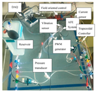
The experimental set-up for evaluation of trapezoidal and FOC control is shown in Figure 5. Throughout the testing phase, speed settings were adjusted to different rates. The test bench included the AFE System pump (Flow Forward Medical, Olathe, KS, USA); the FOC board (InstaSPIN-FOC enabled C2000 Piccolo LaunchPad, Texas Instrument, Dallas, TX, USA); the trapezoidal board (Flow Forward Medical, Olathe, KS, USA); the data acquisition system (NI cDAQ-9174, NI 9232 (for vibration measurement) and NI 9237 c series (for pressure measurement); National Instrument, Austin, TX, USA); a reservoir representing the right atrium; tubing replicating the venous system in the hand, including the cephalic vein; a one-axis piezoelectric vibration sensor mounted on the top of the pump housing in the axial direction (CA-YD-119, Sinocera, Jiangsu, China); a current sensor (SparkFun Electronics, Niwot, CO, USA); a PWM generator module (BU0579, Hidream); and pressure transducers (BD DTX Plus™ disposable medical, Bunzl Healthcare, London, UK).
Figure 6 illustrates the block diagram of the sensorless trapezoidal commutation, and Figure 7 illustrates the block diagram for the FOC control of the AFE System.
As shown in Figure 6, the sensorless trapezoidal commutation mainly consists of an a4941 chip (Allegro Microsystems, Worcester, MA, USA), which is a fully integrated trapezoidal three-phase sensor-less (direct BEMF sensing) BLDC motor driver with control, gate drive, power stage, and analogue peripherals. A frequency generation pin contains speed information and speed control is achieved through variable voltage applied to the stator phases through PWM with varying duty cycles. There is a minimum of 6 μs for the duty cycle set by default, which limits the minimum possible speed. The PWM generator in Figure 6 is a 555 chip set in an astable multivibrator configuration with a 50 kΩ potentiometer to change the duty cycle. The PWM frequency for the a4941 should be in the range of 15–30 kHz.
The “FG” pin of the a4941 is a speed output signal and has an open drain structure which requires a pull up resistor (15 kΩ here). The FG output of the driver was connected to the clock of a dual D-type flip-flop in order to divide the frequency by two because of the motor four poles, and then smoothed and measured on an oscilloscope.
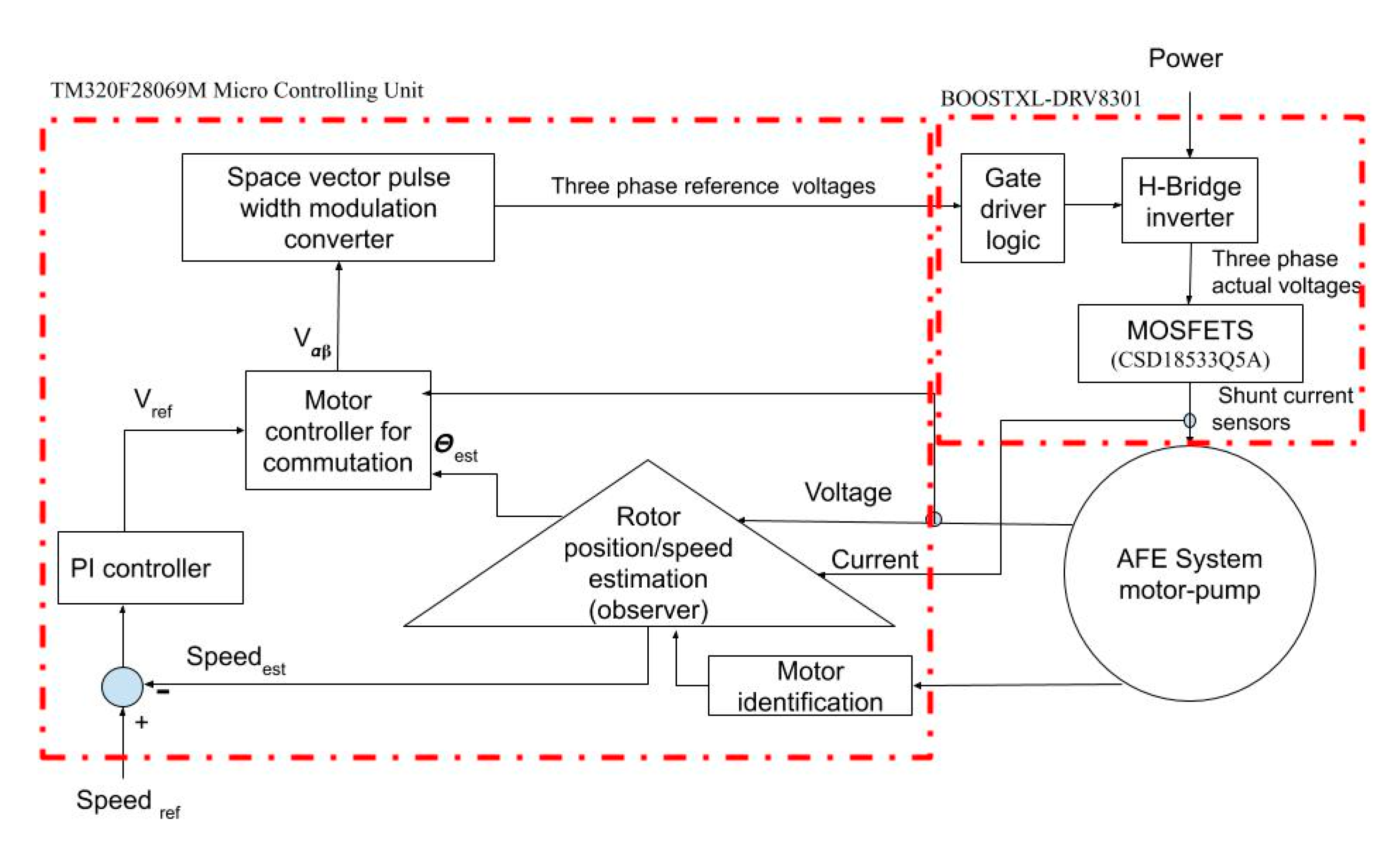
FOC, as shown in Figure 7, consists of a microcontroller (that holds the FOC program), a power stage, and a gate driver. As a software-based technique, the FOC was developed on the Texas Instruments TM320F28069M micro controlling unit. A 3-phase brushless dc drive stage (BOOSTXL-DRV8301, Texas Instrument, Dallas, TX, USA) was used, which consisted of a gate driver logic and H-bridge inverter (the DRV8301, Texas Instrument, Dallas, TX, USA), and a power stage (CSD18533Q5A N-Channel NexFET Power MOSFETs, Texas Instrument, Dallas, TX, USA) to commutate the AFE System motor.
While in trapezoidal control, the rotor position is derived from the sensed BEMF signal; in FOC, this is achieved from a software-based rotor position observer (sliding mode observer). As discussed previously, the rotor position observer requires accurate measurements of stator resistance, stator inductance, and flux (Table 1).
The FOC rotor position observer further requires phase current and voltage feedback signals. Table 2 illustrates the required scaling for current and voltage sensing feedbacks on the DRV 8301 driver based on the AFE System specification. The current sense shunt resistors were scaled to the AFE System maximum current (0.2 A). Similarly, the parallel resistors in the voltage sense circuit were scaled for the AFE System motor nominal voltage (15.5 V); the series resistors were also changed to create a filter pole equivalent to the AFE System motor maximum frequency of 200 Hz.
As additional requirements for the sliding mode observer model, Table 3 illustrates the PWM and control frequencies identified for estimation of rotor position, as presented in Section 1.2. Given that the AFE System has a low inductance motor (with low time constant (L/R = 212 × 10-6 s) derivable from Table 1), higher PWM frequencies (and thus higher control frequencies) were utilised in order to avoid current ripples [39]. Control frequency is half of the PWM frequency and defines the frequency for the iq, id, Park, and SVPWM routines.
The implementation of trapezoidal and FOC control allowed the measures of current ripple, vibration, and power consumption for both FOC and trapezoidal control to be determined. Vibration signals were measured at different motor speeds, and evaluated in MATLAB software (R2017a, MathWorks Inc., Natick, MA, USA) using different techniques mainly power spectrum density to evaluate the overall vibration associated with the trapezoidal and FOC control.
3. Experimental Results
The BEMF voltage and phase current were measured as two contributors to torque (Equation (1)) and hence the torque ripple. The AFE System phase BEMF voltage profile was checked at its stator when the motor was rotated with a prime mover at speed of 150 Hz while its terminals were open (Figure 8). The sinusoidal trend of the BEMF waveform indicate that the AFE System is a PMSM motor.
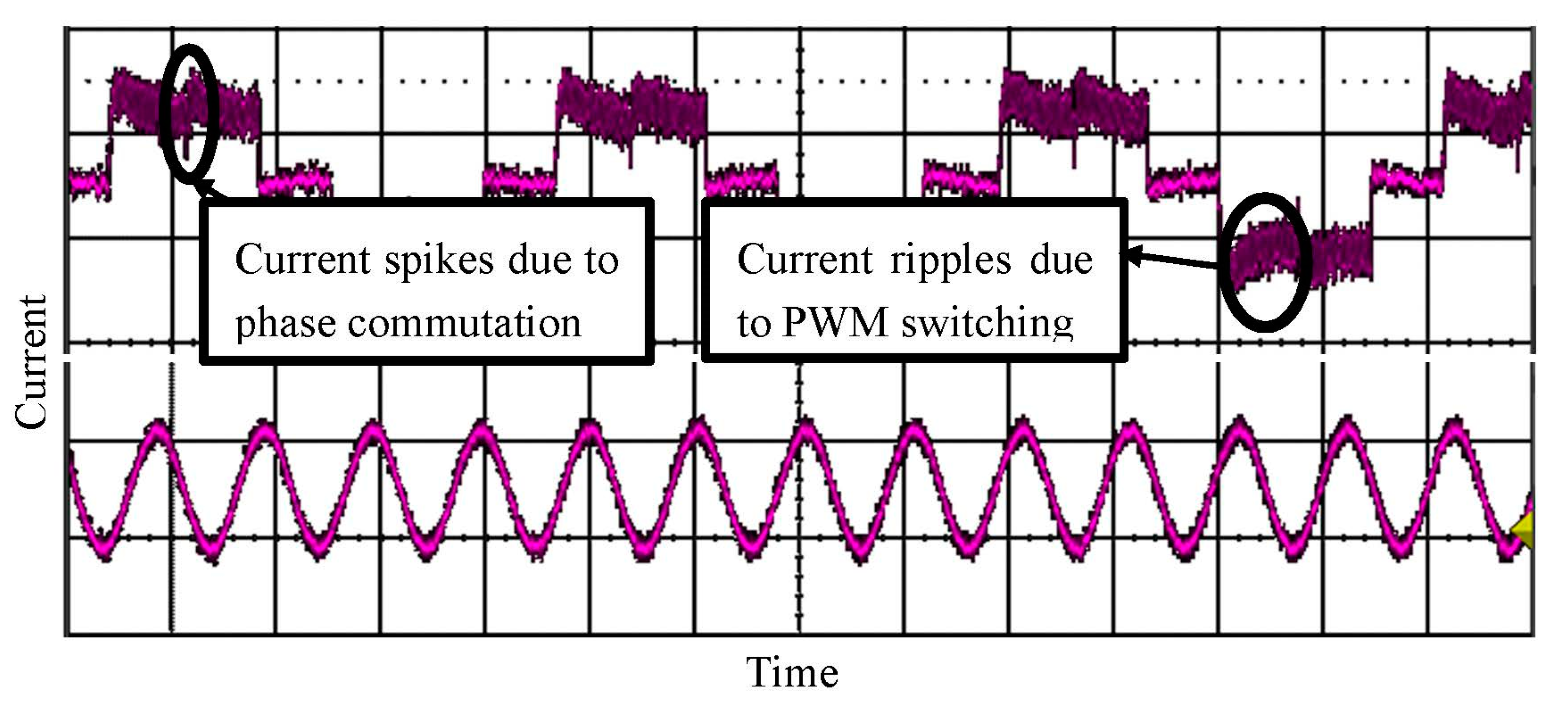
Phase current was measured at 3800 rev/min which showed a quasi-state trend of the trapezoidal and sinusoidal with FOC, as expected (Figure 9).
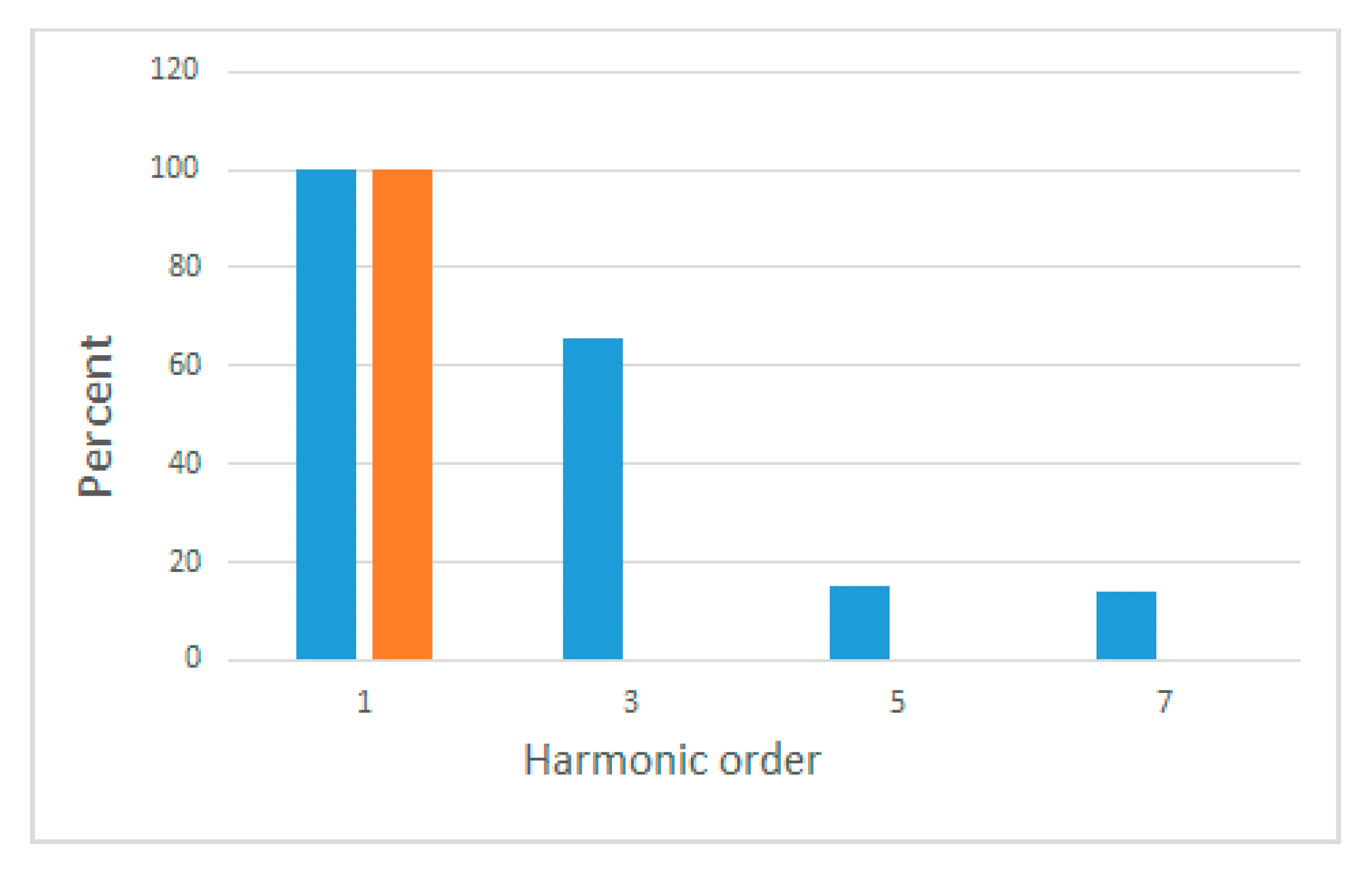
Being a non-sinusoidal wave, the Fourier transform of the current in trapezoidal control was acquired in MATLAB software (R2017a, MathWorks Inc., Natick, MA, USA) and showed considerable harmonics as illustrated in Figure 10; while current in the FOC set-up (Figure 9) was a non-distorted sinusoidal waveform (Figure 10).
The FOC showed significantly lower vibration compared to the trapezoidal control. Figure 11 depicts the vibration of the AFE System motor with trapezoidal and FOC control in logarithmic scale at the motor nominal speed of 4800 rev/min (vibration was sampled at the rate of 1.5 KHz using 200 samples).
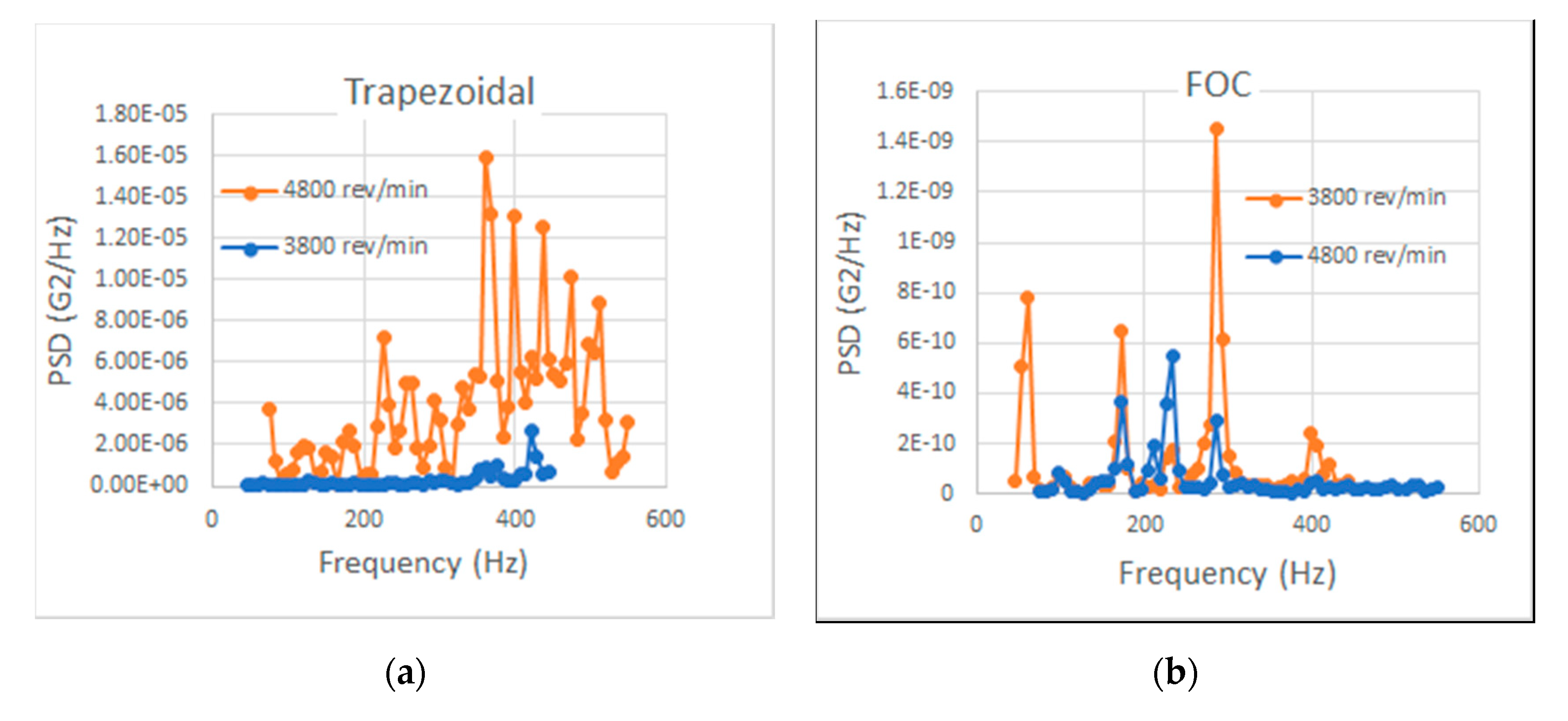
Figure 12 illustrates a significant increase in the vibration amplitude with an increase of speed from 3800 to 4800 rev/min in trapezoidal control, but a decreasing trend with the FOC.
Table 4 illustrates overall vibration (overall power spectrum density amplitude—overall GRMS) at different speeds. The FOC showed the least vibration at 4800 rev/min which is the nominal speed of the motor. The trapezoidal control had increasing vibration at higher speeds.
A further observation in the power spectrum density analysis of Figure 12 was the presence of higher frequency components associated with the trapezoidal control. Table 5 and Table 6 illustrate the change in the two main harmonic components that were present in both techniques: the third harmonics showed an increasing trend in both techniques with an increase in the motor speed. The seventh harmonic had an increasing trend with trapezoidal control while showing a minimum amplitude at the nominal speed with FOC control.
Figure 13 shows the power consumption of the AFE System with the rising trend of the trapezoidal control which becomes significantly higher than that of the field oriented controller at higher speeds. This is due to vibration which increases with the trapezoidal control, while it decreases with the FOC. This reduction in vibration can cancel out the higher electrical energy required at higher speeds. The high power consumption of the trapezoidal controller limited the maximum achievable speed to 4800 rev/min due to the current rating of the motor windings.
4. Discussion
FOC control required more complicated software settings and accurate identification of the motor (Table 1). Current and voltage scaling values were given for the high resolution of current and voltage feedback signals critical for the FOC rotor position observer (Table 2). The AFE System motor was recognised as a low inductance motor with very low time constant. The R/L value also suggests an optimum operating speed of approximately 4700 rev/min, which was confirmed in the vibration test having the least vibration at this speed. The rated flux of 0.0014 V/Hz suggested a potential maximum speed of approximately 11,000 rev/min (15.5/0.0014; given a 100% duty cycle and a bus voltage of 15.5 V). With trapezoidal control, a duty cycle of 50% was achieved; however, with SVPWM as part of FOC, the desired full duty cycle of 100% was reached.
Through analysis of current ripple, vibration and power consumption, the performance of trapezoidal and FOC controllers were thus compared. As expected, the AFE System motor current was a quasi-square waveform with trapezoidal control containing mainly the third harmonic, and also a significant quantity of ripples due to PWM switching and phase commutation; while the phase current in the FOC showed a similar sinusoidal trend to the motor BEMF waveform. The current harmonics present in the phase current (in the trapezoidal control) along with the identified sinusoidal BEMF would suggest higher vibrations due to the torque ripple as implied by the torque equation (Equation (1)). The AFE motor vibration was thus tested with both trapezoidal and FOC control.
In the vibration tests, the overall power spectrum density amplitude was significantly higher for the trapezoidal controller with the difference becoming bigger as speed increased. The increasing trend in overall vibration with speed in the trapezoidal control was due to both the third and the seventh harmonics. On the other hand, the trend was almost decreasing in the FOC control. Although the third harmonic increased in the FOC with increase in the speed, the decrease in the other harmonic cancelled that increase at higher speeds. The FOC control is known for its good performance at higher speeds which agrees with the findings of this paper. In particular, the FOC set-up showed its best performance at the nominal speed because of the accuracy of the rotor position estimation at the nominal speed due to the dependency of the rotor position observer to the defined motor parameters. On the other hand, the deficiencies resulting from mechanical unbalance, evident in the third harmonic, became more dominant at the higher speeds.
The current work studied the distortion in phase current as a result of combination of both the commutation technique (FOC versus trapezoidal) combined with the rotor position estimation technique (zero-crossing versus the FAST observer), and the modulation technique (SVPWM versus PWM). The FOC controller with SVPWM and the FAST observer effectively reduced motor vibration at all speeds, especially higher speeds. A further observation was that the higher order harmonics were less significant with the FOC controller which suggested that the amplitude of the higher vibrational harmonics could be a measure of the performance of the whole commutation and drive system. The seventh harmonic was the primary measure for the performance of the commutation and drive system together, as the difference between the seventh-order vibration harmonic in the FOC set-up and the trapezoidal set-up increased as speed increased. In addition, the third harmonic was related to mechanical structural deficiencies, such as looseness of the rotor bearings, as it increased with the increase in speed in both trapezoidal and FOC.
A limitation of the vibration experiment was the loading effect of the vibration sensor mass in relation to the small pump mass, distorting the measured vibration. The choice of the vibration sensor was based on a trade-off between the size of the sensor and its noise level. Since smaller sensors have lower loading effect but, at the same time, have less built in crystal which degrades signal to noise ratio. This issue could be addressed in further research using laser displacement sensors to achieve more precise measurements. Power consumption was evaluated at the power supply which included mechanical power, electrical power used by each driver, and energy wasted in vibration and noise. It was observed that the system power consumption was greater with the trapezoidal control at speeds above 1800 rev/min compared with the FOC. Higher power consumption with trapezoidal control was due to higher current ripples, and thus harmonics, while the power consumption increased only slightly with the FOC. The increase in speed, with no corresponding increase in electrical power consumption, was due to less energy wasted which was caused by vibration in FOC.
5. Conclusions
Motor vibration is a particularly important factor in medical devices, as it is associated with power consumption (affecting the battery lifetime), durability of mechanical parts, patient comfort, and haemolysis in blood pumps. Vibration and high power consumption result in higher temperatures and the waste of energy in the form of heat, which can also contribute to blood thrombosis in blood-contacting devices. Prompted by a previously established lack of research into drive system effects on motor vibration in medical devices, the primary aim of the research presented in this paper was to reduce the vibration and power consumption of the AFE System blood pump through improvements in its drive system and torque ripple reduction, by substituting its trapezoidal controller with FOC controller. To prove the effect of power-quality in terms of distortion and harmonics in motor phase current, we compared two extreme scenarios of trapezoidal control of a PMSM motor with zero-crossing rotor position estimation, and PWM modulation (all three are known to increase torque ripple), with a field oriented control with a high performance rotor position observer and SVPWM modulation. The trapezoidal technique generated non-sinusoidal phase currents, incorporated zero-crossing BEMF rotor position estimation technique, which inherently generates a 30° error in rotor position estimation, and PWM modulation. On the other hand, the FOC technique generated sinusoidal phase currents in agreement with the PMSM BEMF voltage waveform. It incorporated a precise proprietary rotor position observer with real-time stator resistance calibration, and SVPWM modulation, both known for less phase current distortion. Further vibration comparison is suggested as a future study to find the separate contribution of the commutation technique and the rotor position estimation technique versus the modulation technique, on the seventh harmonic amplitude and thus the overall power consumption.
Upon implementation, we examined trapezoidal control and FOC set-ups for vibration as well as power consumption. The FOC set-up showed a considerably reduced vibration at all speeds, particularly at the AFE System nominal speed. The high vibration of the trapezoidal control contained high frequency components which increased significantly with speed. The seventh-order vibration harmonic was found to be directly related to phase current distortion, and the third to the unbalance. Power consumption of the AFE System with the FOC showed a constant value at different speeds approximately equal to its nominal power rating. However, power consumption was significantly increased with the increase of speed in the case of trapezoidal control. Furthermore, the low power consumption (and thus lower winding currents) in the FOC technique made it possible to reach higher speeds of more than twice the nominal speed, significantly exceeding speeds attained in trapezoidal control. The research established that the AFE System motor will perform significantly better with an FOC controller, compared to a trapezoidal controller, considering vibration and power efficiency. The higher efficiency will increase run time between battery exchanges of the AFE System pump. As a software based solution, the FOC has the potential of providing maximum flexibility and provide an effective hardware solution for automatic control of the AFE System motor beyond the speed control making possible the integration of an outer motor control with the speed control in a single microcontroller unit which is the focus of further study.
Author Contributions
Conceptualization, F.G., F.Y., L.V. and G.T.; methodology, F.G. and L.V.; validation, F.G. and G.T.; formal analysis, F.G., L.V. and G.T.; investigation, F.G.; resources, G.T.; data curation, F.G., F.Y., L.V. and G.T.; writing—original draft preparation, F.G.; writing—review and editing, F.G., F.Y., L.V. and G.T.; supervision, F.Y., L.V. and G.T. All authors have read and agreed to the published version of the manuscript.
Funding
This research received no external funding.
Conflicts of Interest
The authors declare no conflict of interest.
References
- Birajdar, R.; Patil, R.; Khanzode, K. Vibration and noise in centrifugal pumps-Sources and diagnosis methods. In Proceedings of the 3rd International conference on Integrity, Reliability and Failure, Porto, Portugal, 20–24 July 2009; pp. 20–24. [Google Scholar]
- Qian, K.X. Experience in reducing the hemolysis of an impeller assist heart. ASAIO Trans. 1989, 35, 46–53. [Google Scholar]
- Girdhar, P.; Moniz, O. Practical Centrifugal Pumps; Elsevier: Amsterdam, The Netherlands, 2011. [Google Scholar]
- Hsiao, C.-Y.; Yeh, S.-N.; Hwang, J.-C. A Novel Cogging Torque Simulation Method for Permanent-Magnet Synchronous Machines. Energies 2011, 4, 2166–2179. [Google Scholar] [CrossRef]
- Hwang, M.-H.; Lee, H.-S.; Cha, H.-R. Analysis of Torque Ripple and Cogging Torque Reduction in Electric Vehicle Traction Platform Applying Rotor Notched Design. Energies 2018, 11, 3053. [Google Scholar] [CrossRef] [Green Version]
- Li, Y.; Chai, F.; Song, Z.; Li, Z. Analysis of Vibrations in Interior Permanent Magnet Synchronous Motors Considering Air-Gap Deformation. Energies 2017, 10, 1259. [Google Scholar] [CrossRef]
- Carlson, R.; Lajoie-Mazenc, M.; Fagundes, J. Analysis of torque ripple due to phase commutation in brushless DC machines. IEEE Trans. Ind. Appl. 1992, 28, 632–638. [Google Scholar] [CrossRef]
- Li, X.M.; Jiang, G.K.; Chen, W.; Shi, T.N.; Zhang, G.Z.; Geng, Q. Commutation Torque Ripple Suppression Strategy of Brushless DC Motor Considering Back Electromotive Force Variation. Energies 2019, 12, 1932. [Google Scholar] [CrossRef] [Green Version]
- Hung, J.; Ding, Z. Design of currents to reduce torque ripple in brushless permanent magnet motors. IEE Proc. B Electr. Power Appl. 1993, 140, 260. [Google Scholar] [CrossRef]
- Tan, B.; Hua, Z.; Zhang, L.; Fang, C. A New Approach of Minimizing Commutation Torque Ripple for BLDCM. Energies 2017, 10, 1735. [Google Scholar] [CrossRef] [Green Version]
- Al-Obaidi, A.R. Investigation of effect of pump rotational speed on performance and detection of cavitation within a centrifugal pump using vibration analysis. Heliyon 2019, 5, e01910. [Google Scholar] [CrossRef] [Green Version]
- Kawahito, K. Transformation of vibration signals in rotary blood pumps: The diagnostic potential of pump failure. J. Artif. Organs 2013, 16, 393–396. [Google Scholar] [CrossRef]
- Locke, D.H.; Swanson, E.S.; Walton, J.F.; Willis, J.P.; Heshmat, H. Testing of a Centrifugal Blood Pump with a High Efficiency Hybrid Magnetic Bearing. ASAIO J. 2003, 49, 737–743. [Google Scholar] [CrossRef] [PubMed]
- Donolo, P.D.; Bossio, G.R.; De Angelo, C.; García, G.; Donolo, M.A. Voltage unbalance and harmonic distortion effects on induction motor power, torque and vibrations. Electr. Power Syst. Res. 2016, 140, 866–873. [Google Scholar] [CrossRef]
- Lazor, M.; Stulrajter, M. Modified field oriented control for smooth torque operation of a BLDC motor. 2014 ELEKTRO 2014, 180–185. [Google Scholar] [CrossRef]
- Goswami, V.M.; Vakharia, K. High Performance Induction Machine Drive Using Rotor Field Oriented Control. In Proceedings of the 2019 International Conference on Intelligent Sustainable Systems (ICISS), Palladam, India, 21–22 February 2019; pp. 559–564. [Google Scholar]
- Abdelrahem, M.; Hackl, C.; Kennel, R. Implementation and experimental investigation of a sensorless field-oriented control scheme for permanent-magnet synchronous generators. Electr. Eng. 2017, 100, 849–856. [Google Scholar] [CrossRef]
- Zhang, X.; Chen, B.; Zhu, P.; Lei, H. A new method to minimize the commutation torque ripple in trapezoidal BLDC motor with sensorless drive. In Proceedings of the 3rd International Conference on Power Electronics and Motion Control, Beijing, China, 15–18 August 2002; pp. 607–611. [Google Scholar] [CrossRef]
- Lu, H.; Zhang, L.; Qu, W. A New Torque Control Method for Torque Ripple Minimization of BLDC Motors with Un-Ideal Back EMF. IEEE Trans. Power Electron. 2008, 23, 950–958. [Google Scholar] [CrossRef]
- Abu Hassan, M.A.; Abdullah, A.R.; Bahari, N.; Sabri, M.I.M. Efficiency Comparison of Trapezoidal and Sinusoidal Method for Brushless DC Motor Drive. Appl. Mech. Mater. 2015, 785, 248–252. [Google Scholar] [CrossRef]
- Lin, Y.-N.; Chen, C.-L. Automatic IM parameter measurement under sensorless field-oriented control. IEEE Trans. Ind. Electron. 1999, 46, 111–118. [Google Scholar] [CrossRef]
- Wang, F.; Zhang, Z.; Mei, X.; Rodríguez, J.; Kennel, R.M. Advanced Control Strategies of Induction Machine: Field Oriented Control, Direct Torque Control and Model Predictive Control. Energies 2018, 11, 120. [Google Scholar] [CrossRef] [Green Version]
- Rafaq, M.S.; Jung, J.-W. A Comprehensive Review of State-of-the-Art Parameter Estimation Techniques for Permanent Magnet Synchronous Motors in Wide Speed Range. IEEE Trans. Ind. Inform. 2020, 16, 4747–4758. [Google Scholar] [CrossRef]
- Liu, Y.; Zhu, Z.; Howe, D. Commutation-Torque-Ripple Minimization in Direct-Torque-Controlled PM Brushless DC Drives. IEEE Trans. Ind. Appl. 2007, 43, 1012–1021. [Google Scholar] [CrossRef]
- Su, G.-J.; McKeever, J. Low-Cost Sensorless Control of Brushless DC Motors With Improved Speed Range. IEEE Trans. Power Electron. 2004, 19, 296–302. [Google Scholar] [CrossRef]
- Loree, H.M.; Agyapong, G.; Favreau, E.G.; Ngai, G.A.; Tansley, G.D.; Dixon, B.S.; Franano, F.N. In Vitro Study of a Medical Device to Enhance Arteriovenous Fistula Eligibility and Maturation. ASAIO J. 2015, 61, 480–486. [Google Scholar] [CrossRef] [PubMed]
- Krause, P.C.; Wasynczuk, O.; Sudhoff, S.D. Analysis of Electric Machinery and Drive Systems, 3rd ed.; Wiley: Hoboken, NJ, USA, 2013. [Google Scholar]
- Xu, W.-J. Permanent Magnet Synchronous Motor with Linear QuadraticSpeed Controller. Energy Procedia 2012, 14, 364–369. [Google Scholar] [CrossRef] [Green Version]
- Grzesiak, L.M.; Tarczewski, T.; Mandra, S. Permanent magnet synchronous servo-drive with state position controller. In Proceedings of the 2008 13th International Power Electronics and Motion Control Conference, Poznan, Poland, 1–3 September 2018; pp. 1071–1076. [Google Scholar]
- Ustun, O.; Kivanc, O.C.; Senol, S.; Fincan, B. On Field Weakening Performance of a Brushless Direct Current Motor with Higher Winding Inductance: Why Does Design Matter? Energies 2018, 11, 3119. [Google Scholar] [CrossRef] [Green Version]
- Soong, W.L.; Ertugrul, N. Field-weakening performance of interior permanent-magnet motors. IEEE Trans. Ind. Appl. 2002, 38, 1251–1258. [Google Scholar] [CrossRef]
- Zeng, Z.; Zhu, C.; Jin, X.; Shi, W.; Zhao, R. Hybrid Space Vector Modulation Strategy for Torque Ripple Minimization in Three-Phase Four-Switch Inverter-Fed PMSM Drives. IEEE Trans. Ind. Electron. 2016, 64, 2122–2134. [Google Scholar] [CrossRef]
- Liu, X.; Du, J.; Liang, D. Analysis and Speed Ripple Mitigation of a Space Vector Pulse Width Modulation-Based Permanent Magnet Synchronous Motor with a Particle Swarm Optimization Algorithm. Energies 2016, 9, 923. [Google Scholar] [CrossRef] [Green Version]
- Park, R.H. Two-reaction theory of synchronous machines-II. Trans. Am. Inst. Electr. Eng. 1933, 52, 352–354. [Google Scholar] [CrossRef]
- Zaihidee, F.M.; Mekhilef, S.; Mubin, M. Robust Speed Control of PMSM Using Sliding Mode Control (SMC)—A Review. Energies 2019, 12, 1669. [Google Scholar] [CrossRef] [Green Version]
- Sabanovic, A. Variable Structure Systems with Sliding Modes in Motion Control—A Survey. IEEE Trans. Ind. Informatics 2011, 7, 212–223. [Google Scholar] [CrossRef]
- Kim, H.; Son, J.; Lee, J. A High-Speed Sliding-Mode Observer for the Sensorless Speed Control of a PMSM. IEEE Trans. Ind. Electron. 2011, 58, 4069–4077. [Google Scholar] [CrossRef]
- M’Hamed, L.; Zakaria, G.; Khireddine, D. A Robust Sensorless Control of PMSM Based on Sliding Mode Observer and Model Reference Adaptive System. Int. J. Power Electron. Drive Syst. 2017, 8, 1016–1025. [Google Scholar] [CrossRef] [Green Version]
- Texas Instruments. InstaSPIN-FOC™ and InstaSPIN-MOTION™ User’s Guide; Literature Number: SPRUHJ1A; Texas Instruments: Dallas, TX, USA, 2013. [Google Scholar]
Figure 1.
The Arteriovenous Fistula Eligibility (AFE) System [26]. Figure (a) illustrates the pre-treatment condition with a non-dilated vein. Vein dilation is achieved through pumping non-pulsatile blood from the superior vena cava to the cephalic vein (b), and consequently gradually increasing shear stress at the vessel wall (WSS) to approximately 4 Pa in the cephalic (b,c) [26]. Figure (d) illustrates a dilated vein after 10–14 days: the AFE System is removed and thereafter an arteriovenous fistula (AVF) is created by connecting the dilated vein to the adjacent artery.

Figure 2.
Field oriented control algorithm: is the rotor position; is calculated from and ; Clarke and Park transforms are performed; transformed dc currents are compared with the desired values (command signals) for torque control; reverse Clarke and Park transforms are performed in order to generate three sinusoidal voltages for commutation of the three stator coils (, , ).

Figure 3.
(a) Clarke transform; (b) Park transform.

Figure 4.
Sliding mode observer block diagram.

Figure 5.
Test bench for trapezoidal and field oriented control (FOC) control evaluation.

Figure 6.
Diagram of the trapezoidal experimental set-up. The a4941 trapezoidal driver has five output pins: OUTA, OUTB, OUTC (connected to the three stator coils), CTAP (connected to the motor centre tap), and FG. The AFE System speed is half of the FG output frequency. The only input pin is the PWM command for speed.

Figure 7.
Diagram of the FOC control with rotor position estimator.

Figure 8.
The AFE System motor shaft connected to a DC prime mover to generate back electro motive force (BEMF) on the AFE System motor windings.
Figure 8.
The AFE System motor shaft connected to a DC prime mover to generate back electro motive force (BEMF) on the AFE System motor windings.

Figure 9.
Phase current waveform for trapezoidal control (top) and FOC (bottom).

Figure 10.
Phase current harmonics (6000 rev/min): trapezoidal commutation (blue), FOC (brown).

Figure 11.
Comparison between FOC and trapezoidal power spectrum density at 4800 rev/min in logarithmic scale.
Figure 11.
Comparison between FOC and trapezoidal power spectrum density at 4800 rev/min in logarithmic scale.

Figure 12.
Vibration amplitude comparison at 3800 rev/min and 4800 rev/min: (a) Trapezoidal; (b) FOC: significant increase in the vibration amplitude with an increase of speed in trapezoidal control, but a decreasing trend with the FOC. Higher frequencies are present in the trapezoidal control.
Figure 12.
Vibration amplitude comparison at 3800 rev/min and 4800 rev/min: (a) Trapezoidal; (b) FOC: significant increase in the vibration amplitude with an increase of speed in trapezoidal control, but a decreasing trend with the FOC. Higher frequencies are present in the trapezoidal control.

Figure 13.
Power consumption of trapezoidal and FOC controllers with bus voltage of 15.5 V; increasing the input power beyond 6 watt did not change the pump speed beyond 4800 rev/min with the trapezoidal controller.
Figure 13.
Power consumption of trapezoidal and FOC controllers with bus voltage of 15.5 V; increasing the input power beyond 6 watt did not change the pump speed beyond 4800 rev/min with the trapezoidal controller.


Table 1.
The AFE System motor identification results.
| Number of pole pairs | 2 |
| Max current (A) | 0.2 |
| Flux and inductance estimation frequency (Hz) | 40 |
| Resistance—phase to phase (Ω) | 5.6 |
| Direct and quadrature inductance (H) | 0.0012 |
| Rated flux (V/Hz) | 0.0014 |
Table 2.
Scaling for current and voltage sensing feedbacks.
| Current sense shunt resistors | 0.2 Ω (3 W, 2512 package) |
| Voltage sense parallel resistors | 37.4 kΩ (0.1 W, 0603 package) |
| Voltage sense series resistors | 10 kΩ (0.1 W, 0603 package) |
Table 3.
PWM and control frequency.
| PWM frequency (KHz) | 60 |
| Control frequency (KHz) | 30 |
| PWM ticks per interrupt service routine (ISR) tick | 2 |
Table 4.
Overall power spectrum density amplitude (overall GRMS) at 3800 and 4800 rev/min.
| Speed | Overall GRMS (Trapezoidal) | Overall GRMS (FOC) |
|---|---|---|
| 1800 rev/min | 0.15274 × 10⁻⁶ | 11.537 × 10⁻⁹ |
| 3800 rev/min | 62.488 × 10⁻⁶ | 19.537 × 10⁻⁹ |
| 4800 rev/min | 416.15 × 10⁻⁶ | 8.030 × 10⁻⁹ |
Table 5.
Power spectrum density (PSD) amplitude of the third harmonic in trapezoidal and FOC control.
Table 5.
Power spectrum density (PSD) amplitude of the third harmonic in trapezoidal and FOC control.
| Speed | GRMS (Trapezoidal) | GRMS (FOC) |
|---|---|---|
| 1800 rev/min | 1 × 10⁻⁸ | <10−11 |
| 3800 rev/min | <10−6 | 1 × 10⁻¹⁰ |
| 4800 rev/min | 1 × 10⁻⁵ | 8 × 10⁻¹⁰ |
Table 6.
PSD amplitude of the seventh harmonic in trapezoidal and FOC control.
| Speed | GRMS (Trapezoidal) | GRMS (FOC) |
|---|---|---|
| 1800 rev/min | 1 × 10⁻⁸ | 5 × 10⁻¹¹ |
| 3800 rev/min | 1 × 10⁻⁶ | 2 × 10⁻⁹ |
| 4800 rev/min | 2 × 10⁻⁵ | <10−10 |
© 2020 by the authors. Licensee MDPI, Basel, Switzerland. This article is an open access article distributed under the terms and conditions of the Creative Commons Attribution (CC BY) license (http://creativecommons.org/licenses/by/4.0/).
Share and Cite
MDPI and ACS Style
Golesorkhie, F.; Yang, F.; Vlacic, L.; Tansley, G. Field Oriented Control-Based Reduction of the Vibration and Power Consumption of a Blood Pump. Energies 2020, 13, 3907. https://doi.org/10.3390/en13153907
AMA Style
Golesorkhie F, Yang F, Vlacic L, Tansley G. Field Oriented Control-Based Reduction of the Vibration and Power Consumption of a Blood Pump. Energies. 2020; 13(15):3907. https://doi.org/10.3390/en13153907
Chicago/Turabian StyleGolesorkhie, Farya, Fuwen Yang, Ljubo Vlacic, and Geoff Tansley. 2020. "Field Oriented Control-Based Reduction of the Vibration and Power Consumption of a Blood Pump" Energies 13, no. 15: 3907. https://doi.org/10.3390/en13153907
Note that from the first issue of 2016, this journal uses article numbers instead of page numbers. See further details here.