1. Introduction
The concept of sustainability is not a novelty, but it is only since 1970 that its understanding has changed fundamentally. According to estimates by the United States, by 2030, 60% of the population will be urban. This gives rise to a question: how the cities may become more efficient and sustainable [
1]? Currently, where the area of building industry is concerned, scientists proceed along a variety of pathways, including inter- and cross-disciplinary developments [
2]. Contemporary environmental design trends have their roots in the 1992 United Nations Conference “Earth Summit”, where the importance of sustainable urban areas was mentioned for the first time. For a number of years, efficient energy design was the issue most enhanced, but health and well-being standards, and use of natural resources are also becoming part of everyday decisions. One of the present major challenges is climate change, which often affects buildings’ performance [
3,
4].
Architectonic design is based on a traditional hand design process which may be described as additive. It is a complicated procedure which includes adding and overlaying various symbols. This method has certain limitations. Firstly, a typical drafting process differs from the cognitive mechanism which supports creativity, which in turn is based mainly on interdependence, and not on the aggregation of data. Secondly, it does not include live conditions. For example, in opposition to a physical model, the created image does not include forces of gravity. Traditional architectonic drawing is based on external processes, i.e., outcomes, calculations or structural typologies. A new form-finding method appeared as early as the 19th century; this approach was initiated by the creation of new architectonic forms through unification of various typology interdependences, forms, materials and physical factors. Pioneers, such as Antonio Gaudi, Frei Otto or Sergio Musmeci chose a single independent parameter analysis of structural shapes—gravity modelling [
5]. This approach became the stepping stone for other factors. Presently, multi-parametric form-finding research includes various data such as: physical forces, geometry, environmental, economic and social parameters. In 1939, Luigi Moretti, an Italian architect, phrased the term “parametric architecture” [
5]. In 1960, his research was presented during a Milano exposition, in his vision of swimming pools, football stadiums and tennis courts. Design parameters were based on a good spectator visibility and the economic feasibility of design. The used calculations generated and optimized both the structural curves and the volume of used concrete. Moretti then said that the parameters and their independence will become a code for a new architectonic language, which must be supported by techniques and tools offered by contemporary science [
5]. This last element appeared to be of utmost importance, as adequate software allows to express the parameters and their relationship through a set of self-correcting procedures.
The introduction of computers into the design process did not initially influence the dominating role of additive design. Pioneer Computer-Aided Design Programs (CAD) were mainly based on an existing approach, and the logistic procedures od drawings simply moved from a draft board to a digital environment. A huge progress took place at the beginning of the 1980s and is still rapidly continuing. Complicated analysis became possible with the use sophisticated computers, and this approach in turn initiated a search for design solutions inaccessible in the prior years. With the development of software, sustainable solutions became a topic covering analyses of alternative urban and building concepts and detailed solutions. New modelling methods are developed as algorithms; instructions carried out by the computer in a step-by-step technique through a chain of clearly defined instructions. Hence, designing a process does not involve a single solution. From the point of design, hoped for efficiency means use of a case best solution for each of the formulated criteria. An optimization request usually deals with the maximizing or minimizing of a real function through a choice of input values [
6]. In case of Architecture choices, optimization usually is associated with structural issues, and efficiency of building materials, achieved through refinement of the object’s shape, dimensions, or topology. Additionally, urban morphology, orientation, efficient use of the plot, functional layout and user comfort are the main parameters which have the highest impact on the buildings costs. Importance is placed on the energy efficiency values required by a whole building [
7], this being the second main optimization goal outside environmental sustainability.
Rapid urbanization and appearance of the Urban Heat Island (UHI) effect have lowered city environmental standards. High pollution levels have a major impact on the relationship between climate factors and new or modernized building volumes located in a city environment, especially where daylighting, sun radiation and use of wind forces are considered [
7,
8,
9]. Those elements are prevailing when dealing with urban sites [
10,
11,
12,
13]. With the development of sophisticated software in the past 15 years, the analysis momentum also moved to this area. For the past decades, wind simulations have become the subject of detailed analyses quickly developing with the appearance of software and fluid mechanics research used within the Computational Fluid Dynamics (CFD). This particular tool checks aerodynamic properties of buildings [
14], and supports the design of hybrid ventilation solutions [
15,
16,
17,
18]. Used on an urban scale, CFD analysis may be the answer to the issue of large-scale city ventilation, often discussed in the smog context. Furthermore, the design of sustainable buildings with disregard to surroundings cannot be considered as a smart option; sustainability must be considered both in the urban scale and for developed sites.
Therefore, application of algorithms, computational fluid dynamics and a variety of other methods has a grave importance especially when a concept building form is discussed [
19,
20]. Operation of buildings uses approximately 36% of the global energy consumption and generates 40% of greenhouse gas emissions, having a high influence on the swiftness of climatic changes. The assessment of energy consumption and efficiency of buildings is used in many countries and run under various complex methods, their choice often depending on national policy directives. Energy modelling is used usually on the advanced design level and not re-run during the construction changes, and later on only rarely assessed against real buildings performance [
21]. Even if the calculated indications sometimes still do not match actual outcomes and on-site measurements are random and incomplete, there is an interest from the investors side as to the establishment of initial data to be used for further decision purposes [
22,
23].
Increasing energy efficiency standards and high standard expectations for indoor environment have also led to a search for more efficient building solutions. This is important especially where building envelope, the main barrier between the external and internal environments, is concerned. A barrier, for which main solutions should be undertaken already in the concept phase and developed in consecutive stages.
Contemporary architectonic design is the outcome of a multidisciplinary approach characterised by a complexity of building forms. The final solution has to fulfil many requirements chosen by the designers, their number often limited due to the complexity of algorithms. Input data usually can be divided into following five basic categories:
Geometry and surroundings—Building’s geometry, including relations with other volumes and orientation relative to the cardinal directions and geographic locations, and solar radiation intensity;
Climatic data—Information sourced from available meteorological data supporting preparation of a prognosis for chosen parameters and time period; most neuralgic prognostic data include: Air temperatures and humidity, wind direction and velocity;
Technical data—energy requirements and efficiency of equipment installed in the building; with this energy input included in the simulations, the outcomes are calculated with a higher precision, especially when the type of ventilation and lighting systems foreseen in the building are included;
Building materials, which together with the chosen building geometry give basic information on envelope’s foreseen insulation, level of daylight available in different areas, heat losses and gains;
Proposed function and its allocation within the building’s limits, has a primary influence on energy flows, with the main emphasis on the number of building users and use periods; this might be vital when considering energy distribution and requirements during the day and night hours.
The above-described data scopes energy efficiency requirements, including the potential use of alternative energy sources, often having impact on construction and maintenance costs. More and more often, prototyping is used in early design stages to verify architectonic choices, later carried on in more detail in the next design stages. As all tools, even those existing nowadays, have their limitations, there is a promise to gain new and more complex fields of application [
24].
The professional ability of architects to undertake challenges when faced with the changing development of contemporary requirements, in a way can be sourced in their skills in computer software programs. CAD techniques modified architectonic design process and equipped design studios with new tools. This approach supports the simulation and optimisation of design choices created on a parametrically controlled virtual 3D building model, describing its geometric and alphanumeric data, defining, i.e., the model’s technical parameters. In this way a computer model has a chance to become a virtual equivalence of a real building before construction. Depending on the choice of data, presently it does not have to be just a simplified form, but a complete digital presentation of a building. Such a model does not limit further design choices. Concept design becomes the main stage for the analysis; choices should be developed and refined at consecutive design phases. The key issue is to create a virtual model with participation of interdisciplinary and often multidiscipline consultants. Parametric character of components, building-oriented features (i.e., walls, windows) allows to undertake the best-case design decisions acceptable both by architects and technical consultants.
Relatively easy modification of parameters gives this virtual model the dynamic ability to simulate the final outcomes of design choices, hence giving a chance to provide a set of optimum decisions [
25]. It also allows architects a choice based on preferable aesthetics, also fulfilling their expectations of other technical consultants scoping economy, environment and alternative energy sources. The selection of parameters is very important, as they simulate possible effects on a virtual model without the requirement to undertake the risks of experimental construction.
These parametric techniques, used together with contemporary technologies often give the sun and wind a status of tool shaping architectonic solutions, often perceived as magnificently aesthetically interpreted features. To allow such a comprehension of architecture, designers already in the early design stages use a virtual geometrical models generating a realistic
chiaroscuro picture. Geographic Information System (GIS) indicates a precise location of a building and contains data to prepare a complex environmental analysis. Contemporary software can be used both to check the efficient energy parameters based on the building’s form and materials used, and include the best-case use of alternative energy sources. This allows more design freedom with new materials and possibilities to achieve aesthetic articulation of building’s envelope. A good example is the use of transparent photovoltaic panels which have the capacity for a high energy potential. This idea was proved in the Blue House build on the campus of University of Niederrein in Mőnchengladbach, Germany [
26], where energy modelling influenced designed features which were not only highly aesthetic, but also allowed electric energy production, efficient sun and daylight control in the interiors. Construction of such buildings would not be possible without the use of the newest tools and technologies used within Computer-Aided Architectonic Design CAAD. This case also proves a change in the architectonic approach to many environmental issues. From the primary energy sources required by all living creatures and plants species, through daylight and shade aesthetic features and the achievement of user friendly standards.
The design of energy-efficient and environmentally friendly buildings can be sourced from economic requirements, legal and social issues. The need to develop efficient and user-friendly sustainable urban spaces and buildings makes such a design especially important. It is also a continuously developing discipline involving research and experimental investments. Growing social awareness stimulates environmentally friendly solutions in many spheres of life, also in architecture and construction. Warsaw, as the largest Polish agglomeration, is more and more influenced by the consequences of inconsiderate human actions. During the last years, as in many other big cities [
27], the main problems are caused by high air pollution emitted by transport systems (generating fumes and noise) and uncontrolled suburban sprawl. Warsaw keenly seeks intelligent design solutions, both in the urban and architectonic scale. It is a city attractive to investors, used for various prestigious construction sites, often presented as the international corporation flagships. One of the most characteristic features is that the urban tissue in the town centre is still being rebuilt after the second world war aftermath. City morphology has been disrupted and in many areas totally destroyed. There are many sites in various stages of misuse: undeveloped, often requiring architectonic and urban upgrade. Unfortunately, not all areas are covered by Master Plans.
2. CASE 1. Sun and Wind Factors as the Main Analysis Criteria
The presented case was prepared based on the investor’s brief and with the main emphasis on the energy efficiency of the building and provision of a possible architectonic detail concept solutions. This implicated a methodology procedure where the preparation of a 3D urban model of surroundings, both existing and foreseen in the near future, was the essential, as use of sun and wind energies were to be included if economically viable. Heating simulations were made in DesignBuilder Software and were based on data presented in
Table 1. Other software used during analyses: BIM Modelling—Autodesk
® Revit, Solar and Radiation Analysis in Autodesk
® Revit environment and Autodesk
® Flow Design for wind analysis.
The aim of the analysis was to establish the best-case efficient energy requirements analysed against an office reference building with given data according to the Polish Building regulations published in a Resolution issued by the Minister of Infrastructure and Construction concerning technical conditions which must be fulfilled by buildings and their location, dated 7.6.2019. The numeric model is designed for a particular climatic zone, weather conditions and design assumptions. Geometry and building main parameters were supplemented with official climatic data, a foreseen number of users, electric lighting system capacity including assumed zoning and efficient use of daylight, required ventilation volumes and equipment. Each of the zones has a predefined heating and ventilation system requirement and assumed use profiles. Simulations were made using data sourced from a standard meteorological year. Hence, the outcomes cannot be treated as site-measured values and calculation process should be repeated at least at every level of the design process.
Outside the constant values depicted in
Table 1, modelling included several alternatives such as volume and existence of an atrium, and the use of sun energy and natural ventilation options. The chosen, case best scenario was then set off against a reference model.
Analyses of energy efficient solutions were treated as leading conditions of design process. Sun radiation simulations were conducted in order to check the daylighting and shading, sunlight radiation levels, potential risk of overheating. Wind flow simulations, observed natural wind paths and potential turbulences appearing in this particular urban context, and were used to check building’s potential for natural ventilation. Finally, conclusions determined a set of conditions for architectural response, and to a large extent were decisive where detail was concerned. Outside energy efficiency, conditions aimed to achieve a high standard and flexible user friendly environment.
The site is located at a crossing of two major roads set out already in the 15th–16th century [
28]. For Krolewska Street, one of the main features is a green landscape of the nearby Saski Park. This street had the status of a major artery for past 200 years and was flanked with important city buildings. It was only at the end of 19th century, when the second street—Marszalkowska—became Warsaw’s hub. Plot was invested in since 1739, but initial building was demolished mid-19th century during the development of the city centre. Later the plot was divided into four smaller ones and destined for multifamily tenement houses, with a three-storey corner house initially designed by Marconi [
28], later extended to five storeys forming a volume characteristic to the pre-war city. This building was destroyed in 1939. Later, a group of low temporary retail pavilions was built in this, and adjoining sites, to be demolished in the first decade of 21st century, leaving the plot undeveloped. Presently, this site is destined for an office building with retail area accessed off the street level. It is well connected with mass transport.
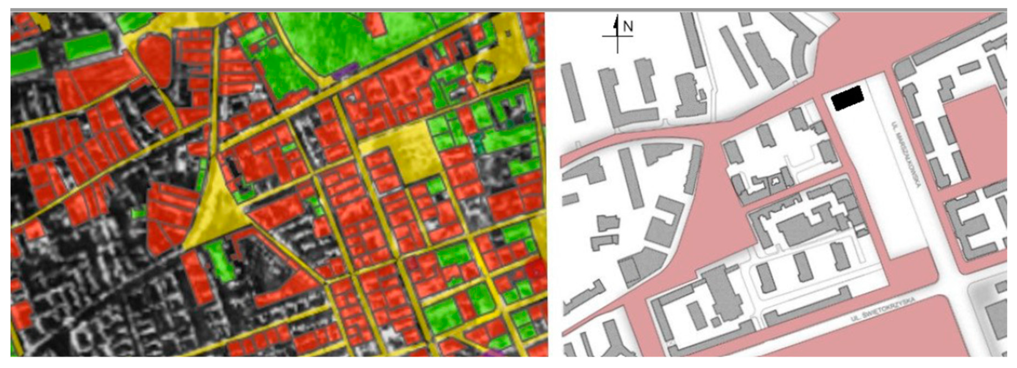
The development of such non-invested and dilapidated city centre sites, with no Master Plan available, is one of Warsaw’s major urban problems. Several design propositions have been made for the discussed area, the most recent proposal dating to 2015. Its main ideas aimed to achieve a higher urban density and to develop a new retail and public network system. The proposed architecture solutions used pre-war morphology characteristics including scale and character. The main emphasis was on the role and value of high-quality public spaces in agglomeration centres, as the social expectations are extremely high. Analyses which might support design and construction of energy-efficient volumes were not included, and remained as an area which should be checked by potential investors. General site development conditions stated in the content of The Study of Conditions and Directions of Spatial Development for the City of Warsaw defines this site as a functional city centre area. Buildings should not exceed 30 m in height, whereas the average intensity indicator should be circa 3.5. The site itself is not listed in Historic Preservation Act, but is in direct vicinity to a historic memorial site. It also bears a status of an urban preservation zone, with strict reference to the pre-war urban layout and building volumes. Present Warsaw tissue is differentiated both functionally and morphologically. There still exist 19th century tenement housing with characteristic internal courtyards, mixed with sites where post-socialistic buildings dating to 1960s and 1970s of the former century were raised without regard to the historic context.
The initial design task was analysis of existing urban tissue.
Figure 1 shows the site’s morphology before 1939 and presently. As already remarked, historic city structure has been highly damaged in this area.
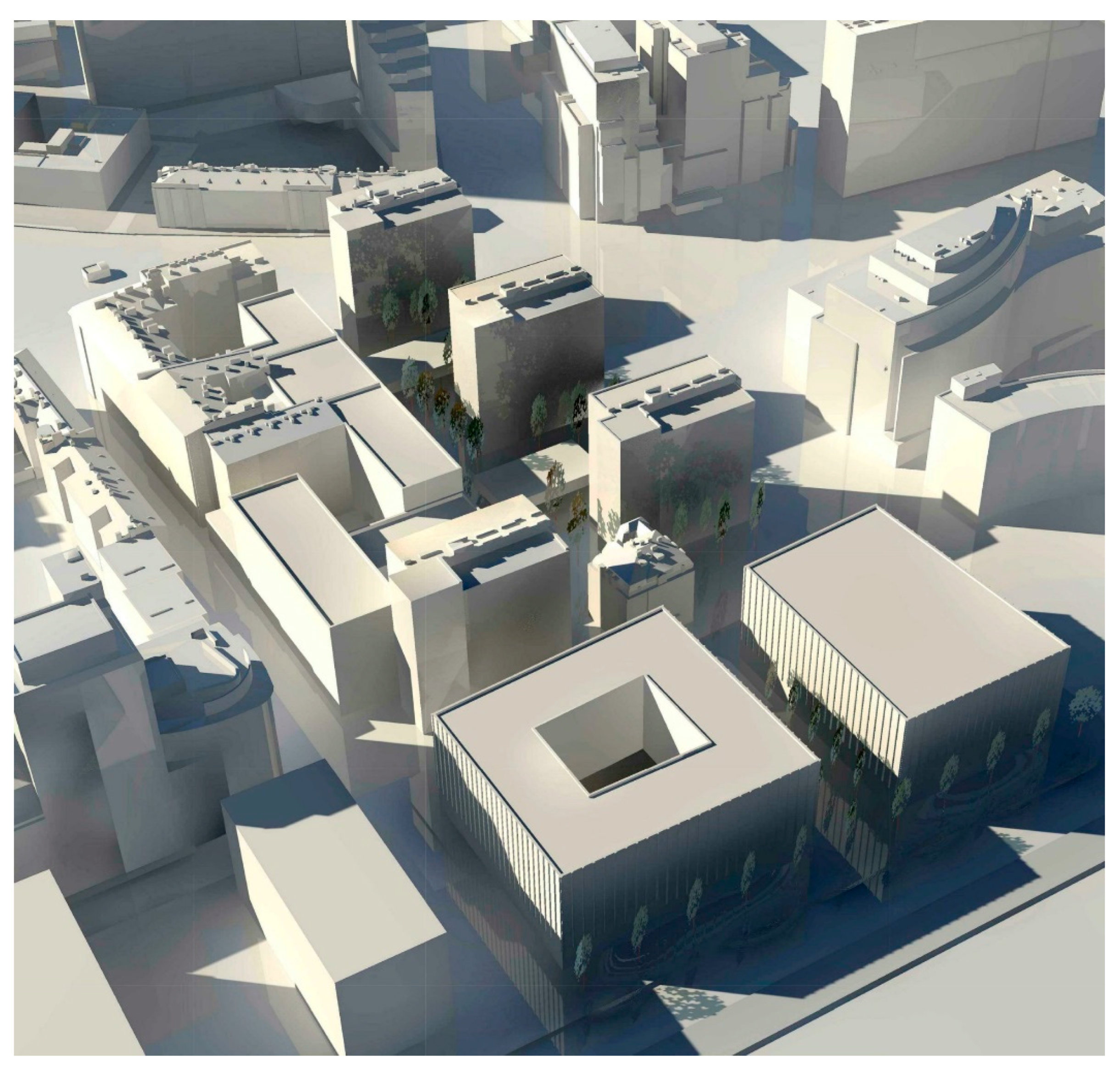
The request posed to the WUT team by the potential investor was to present a solution complementing existing buildings and restoring urban coherence simultaneously with establishing potential energy efficiency solutions. The proposition of a new site development included two office buildings facing a public square (
Figure 2), with the north-facing one subjected for further analysis. The buildings were located on the pre-war plot lines and major decisions included directives from The Study of Conditions and Directions of Spatial Development for the City of Warsaw. Hence, the buildings do not exceed 30 m in height, and the intensity factor is accepted at 3.5.
Initial energy analysis included following data: site characteristics, climatic and geographic data for the site. Preparation of a 3D urban model of existing surroundings was the basing task. The first set of simulation was dedicated to the annual sun radiation analysis. Three reference days were chosen for the daylight and shadow analysis. These included:
21 June—the Summer Solstice for the Northern hemisphere, and the angle of incidence during sun’s peak for Warsaw (52°13′ northern latitude) estimated at 61°14′;
Equinox—for Warsaw, estimated as 37°48′; sunlight conditions were assumed as average annual characteristics;
21 December—the Winter Solstice for the Northern hemisphere, the angle of incidence for Warsaw is estimated at 14°20′—being smallest in the year.
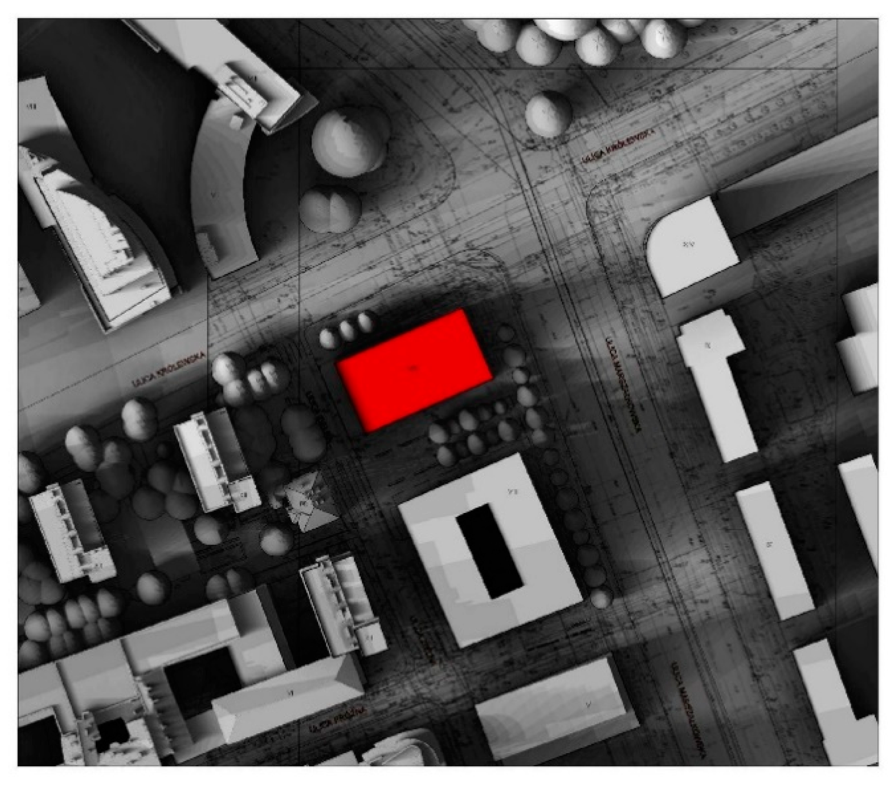
A series of drawings was prepared for each of the reference days, each depicting the placement of the shadow during the sunrise-to-sunset period with a single hour interval. The cumulative outcomes are presented in 3D (
Figure 3), as a single drawing, where all daily analysis are merged to present the 24 h cumulative shadow characteristic.
On the Summer Solstice day with 16 h duration, building exposure to sunlight is the highest. Due to the large angle of sun radiation incidence, shadowing from neighbouring buildings takes place only in the early morning (before 8 a.m.) and in late evening (from 6 p.m.)—hence, outside the office working hours. The proposed volume does not shadow surrounding buildings. North elevation has access to daylight in the early morning hours and in late afternoon (after 3 p.m.). Radiation has a small angle of incidence, hence it does not penetrate the interiors at a level sufficient to be used without artificial light support. Eastern elevation is exposed to sunlight until 11 am. except for 6–7 a.m. when designed volume is strongly overshadowed by a building located on the other side of the street. South elevation has the highest sunlight exposure from 6 a.m. to 5 p.m.—the hours with the highest levels of sunshine. Elevation is not overshadowed by surrounding buildings. Sun radiation falls at a small incidence angle only during the morning hours. The western side is also well exposed to sun radiation (from noon until 6 pm.), with a 10% area shadowed in the late evening by the buildings located off west. Roof of the building has good access to sunlight throughout the day.
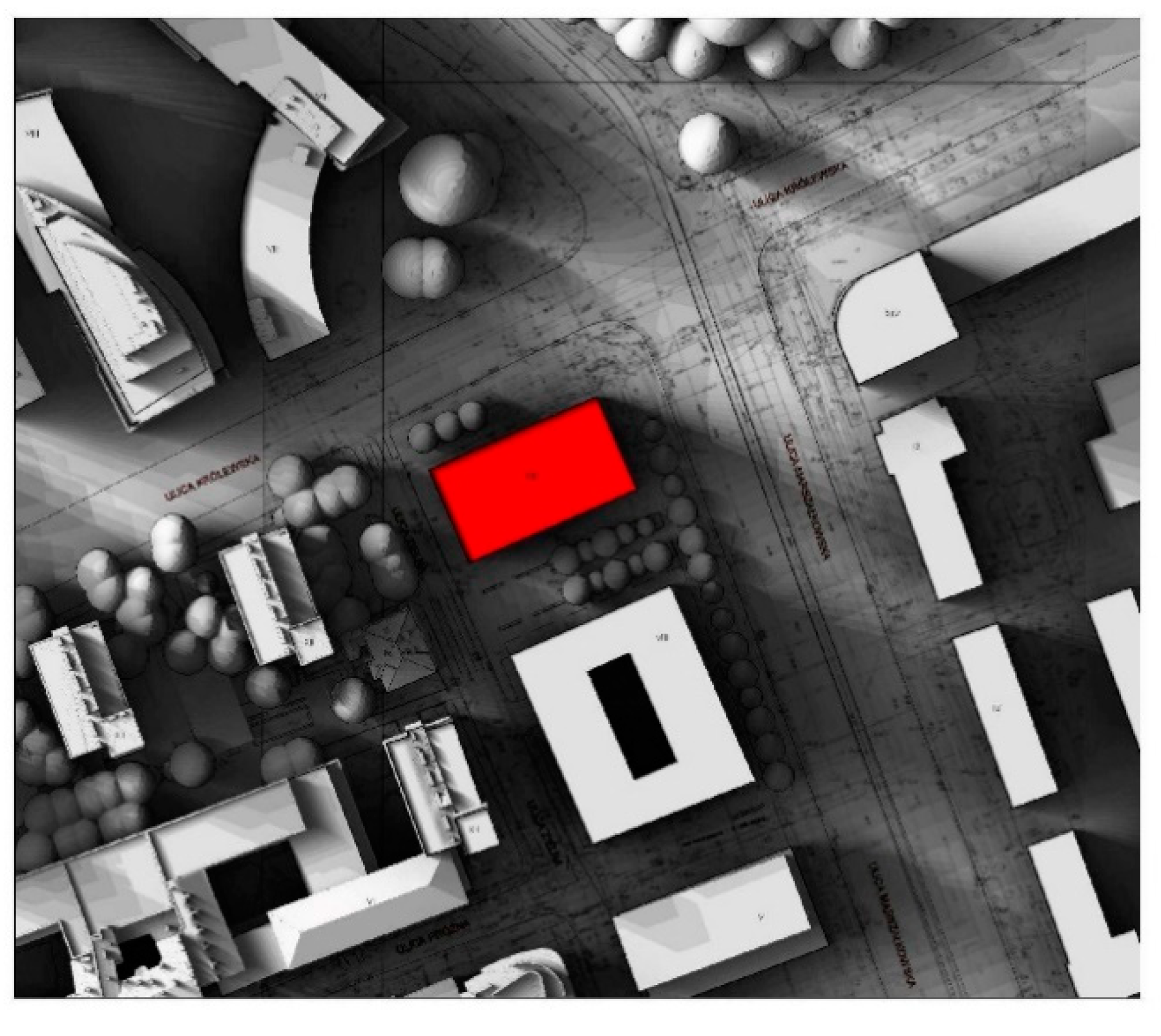
In comparison to Summer Solstice, Spring Equinox (
Figure 4) is characterised with a smaller incidence angle. Hence, shadowing by the neighbourhood buildings becomes an important issue. The duration of daylight hours is circa 12 h. Northern elevation is not subject to direct sun radiation. Eastern elevation is heavily screened in the morning hours, and has access to sunlight only between 8.00–10.30 a.m. South elevation has sunlight from 8 a.m. until 4 p.m. The ground floor and two consecutive floors are highly screened. Three highest levels have good quality access to sun radiation, with the average incidence angle during working hours. Western elevation has sunlight exposition from 11 a.m. to 3 p.m. The new volume is shadowed by neighbouring buildings in the later hours of the day.
Winter solstice has only 8 h of daylight, the smallest duration of daylight hours in a year. The incidence angle is small, which in a dense urban development causes a variety of strong shadows. Direct light is accessible on two last levels of the south and east elevations. Interiors will have access mainly to dispersed daylight. Regardless of the small incidence angle, the roof has good daylight conditions.
Conducted light and shadow analysis gave data as to building’s annual sun radiation conditions. western and southern elevations have similar exposition. Working areas on those sides of the building will have much better daylight conditions, but will bear the risk of overheating during summer months. Western elevation has a short exposition to sunlight in the morning hours, but later on shadowed by a tall (54 m) building off Krolewska Centre. Southern elevation is shadowed throughout most of the year. Nevertheless, it is located parallel to a wide street with a view to a green square on the other side of the road. This location allows better use of dispersed daylight as the main source of light in the office areas. The roof has very good sunlight conditions which gives a potential to mount photovoltaic panels or skylights.
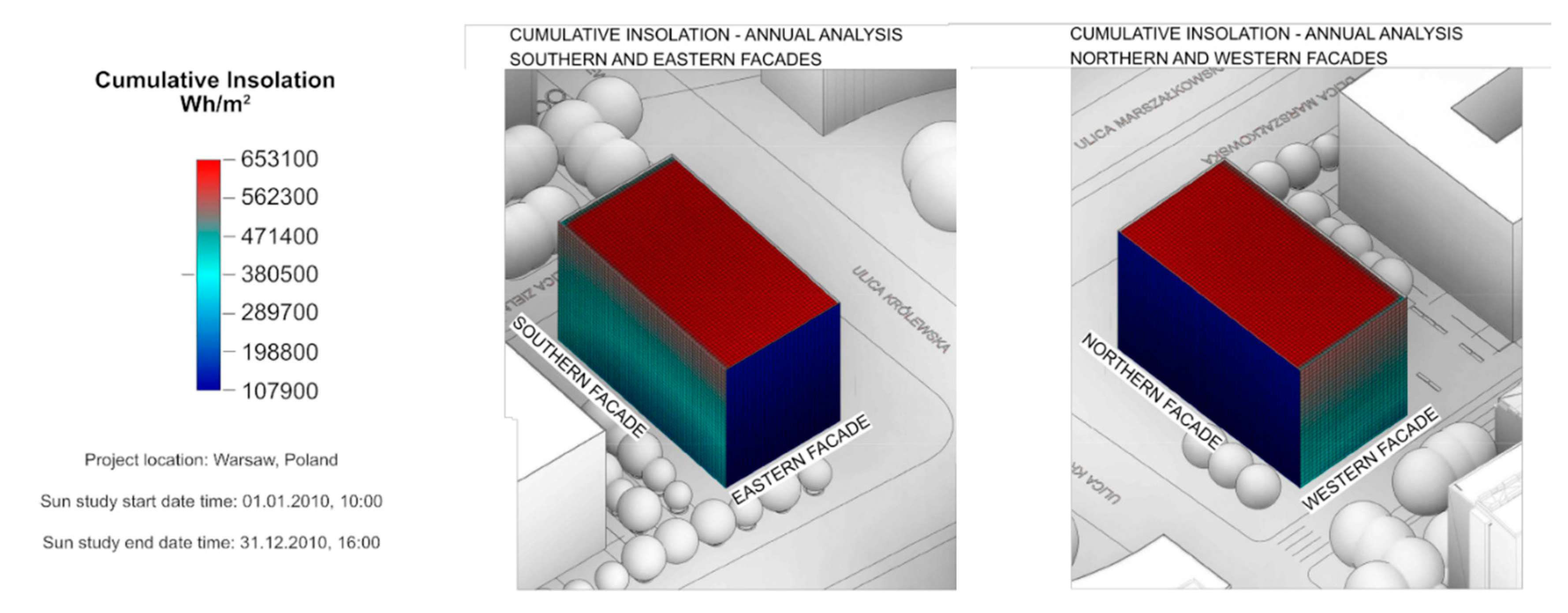
Sun radiation simulations were a consecutive set of analysis aiming at checking the sun radiation potential. Beside Summer and Winter Solstice, Autumn and Spring Equinoxes were chosen as reference days. A complementary analysis which included annual sun radiation energy was also conducted. This particular analysis is based on an additive process of the sun radiation on the chosen surface area. Analysis included both direct and dispersed light, and therefore it was very important to include urban surroundings. The graphic presentation of the outcome is shown on a model, with colours corresponding to particular energy values calculated in Wh/m2. This analysis is indispensable when calculating the economic feasibility of the photovoltaic panels, estimation of possible overheating, efficient use of daylight, and use of sun radiation as alternative energy source during the Winter months.
Annual analysis of the sun radiation energy (
Figure 5) estimates approximate heat gains and potential overheating due to the unfavourable building exposition to sun radiation (
Table 2). Annual potential energy for the roof amounts to circa 650 kWh/m
2. Estimations lead to a conclusion that the roof area may be used to harvest sun energy. Since the angle of incidence is the major efficiency factor, the use of revolving heliostats has been proposed, as the roof is also the area with major overheating risks, use of finishing layers with light reflective coating and higher insulation values is foreseen.
The simulations disclosed that during Summer months, south and west elevations, will be exposed to the risk of overheating, especially where two upper floors are concerned. In this case, active and passive screening systems should be integrated in the building’s envelope as part of the design detail. The use of a double skin façade, or a green living wall is also justified. For east and north elevations, dispersed or reflected daylight should be considered when configuring both the external walls and internal layout. In this case designers should choose aesthetically valuable openings onto the nearby park.
As already mentioned, EFD analyses are based on a simulation of the fluid particles (in case of wind—air particles) in a computer-modelled site. Air flow in urbanised areas may be influenced by volumes located a couple of hundred meters from the chosen measurement site. The complexity of the CFD algorithms affects final simulation outcomes, as they rely on the scale and accuracy of designed detail. In this case, the simulation was made with Autodesk
® Flow Design on a simplified model and a 300-m-radius catchment, which in comparison to existing research can be classified as a micro-scale urban flow simulation model [
30,
31]. Wind velocity data was received from a local meteorological station, located at a 10-km distance. Therefore, the data are approximate for the site (
Table 3), but sufficient at a concept stage. The model used in the Autodesk
® Flow Design was drawn in Autodesk
® Revit as 3D. Flow Design is a software usually used at the concept stage of design and has limited options where grid resolution is concerned. In this case the high standard option was used, with the resolution set at 300%. The inflow boundary conditions were set as the average major wind conditions. Statistic data for Warsaw [
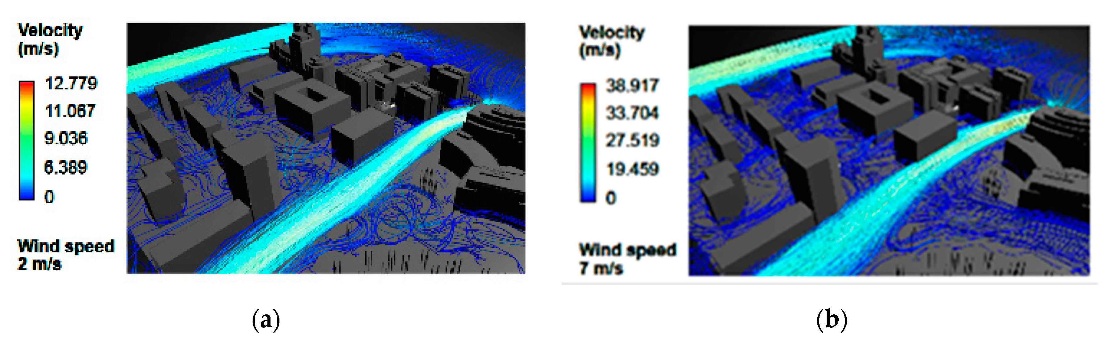
32] discloses that the average major wind direction is from west—27%. Its analysis shows that in the last 18 years wind speed has been estimated at 12.9 km/h (app. 3.6 m/s). The wind speed is measured at 10 m above the ground. Analyses were made for the four cardinal wind directions. The virtual wind tunnel was extend to a 300 m radius and the height set to 98 m, this allowing non-interference with the model boundaries. Urban wind analysis was provided for several different speeds which disclosed the site’s potential. At 2 m/s, wind flow is turbulent and fragmented; a small trickle of quickened flow can be perceived parallel to the east elevation. At 7 m/s, air flow streams can be discerned along two streets. Air movement off eastern and western elevations has a linear character, and there are clearly visible air turbulences at north and south elevations. In case of a prevailing north wind, a single tunnel appears along Marszalkowska Street. There are regular wind turbulences between the designed volume and existing building located at a distance of circa 150 m. Since west wind is prevailing, this analysis has been accepted as the most important. The screen shot in
Figure 6 discloses a single wind stream flowing along Grzybowska and Krolewska. The building located west of designed volume causes deflection of the wind flow towards north-west corner. In turn, this causes the appearance of a strong wind flow along north elevation. Analysis also disclosed weaker wind currents between the buildings parallel to Marszalkowska Street.
Wind analysis proved that existing urban layout is favourable to use natural ventilation solutions. Both building location and the neighbourhood of two major streets show a high ventilation potential for the northern and eastern elevations. Sun radiation analysis indicates that these elevations are shadowed, and may be used as part of a natural ventilation system.
Conclusions from the analysis support the choice of following architectonic design features:
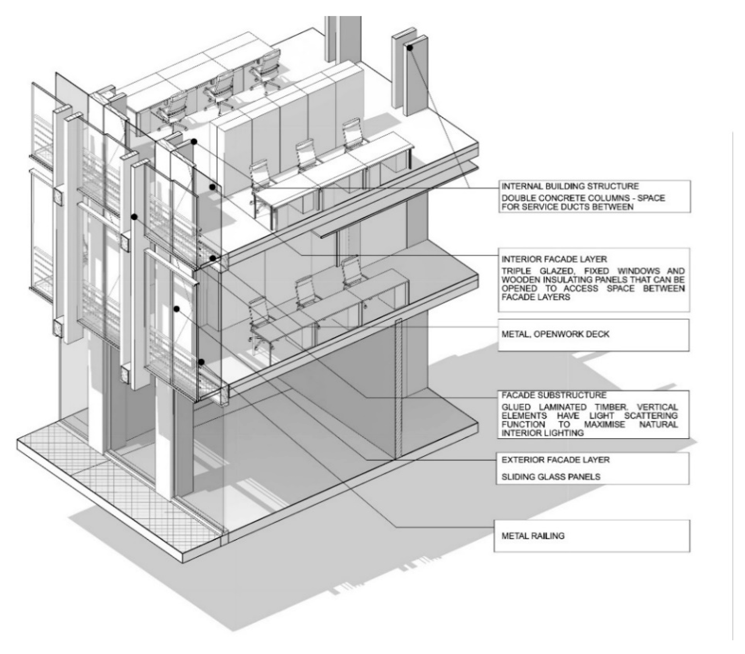
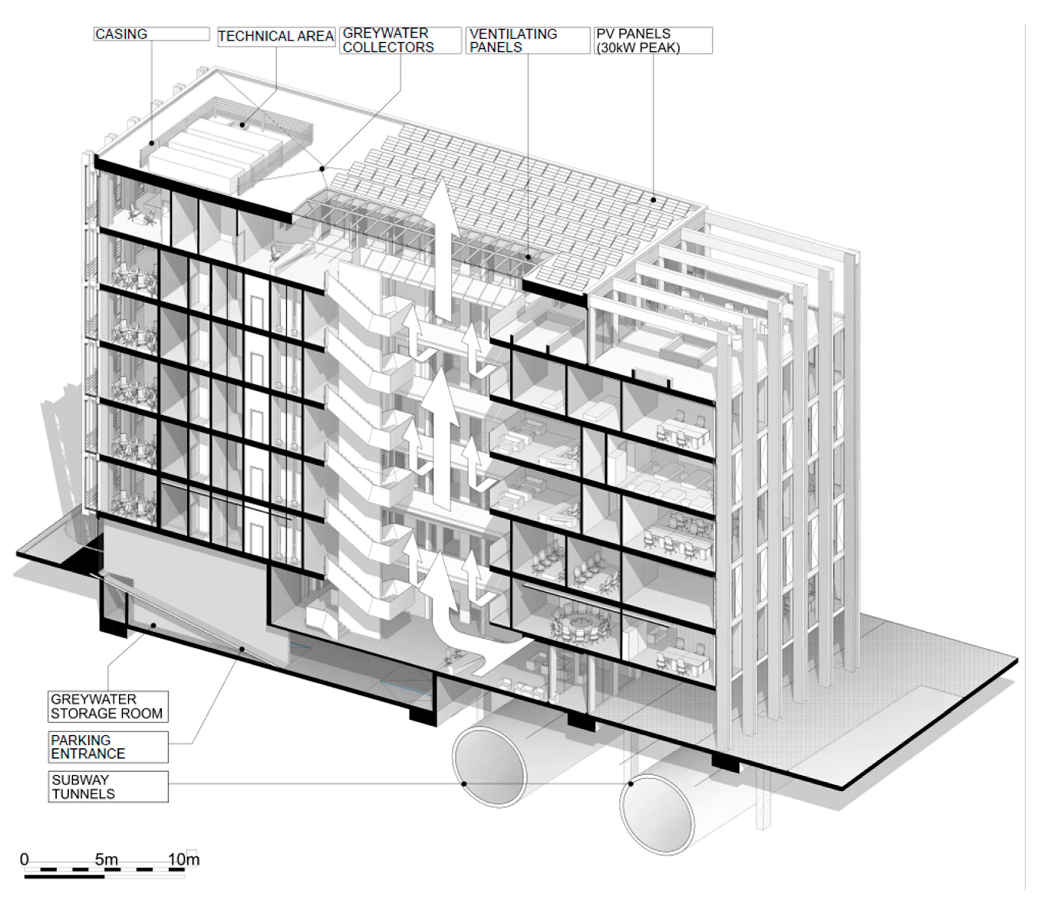
A requirement for a double skin façade for southern and western elevations, as they are overheated during Summer period (
Figure 7); proposed solution is 85 cm in depth additionally screened by technical horizontal steel truss lattice decks, the internal air cushion acts as a thermal buffer; high standard acoustic values are also a valuable part of this solutions. Due to the strict fire regulations in Poland, double skin façade had to be divided into sections with fire-rated horizontal elements sealing every level. Hence, the façade is made from volumes one floor high, with vent openings along the bottom and top edges. This solution lowers the probability of overheating. Possibly at later stages, the external layer of glass will have imbedded photovoltaic cells supporting alternative energy sourcing and acting as additional shading. The chosen solution can be further integrated with the night cooling ventilation system used during the Summer season when the strong west winds prevail.
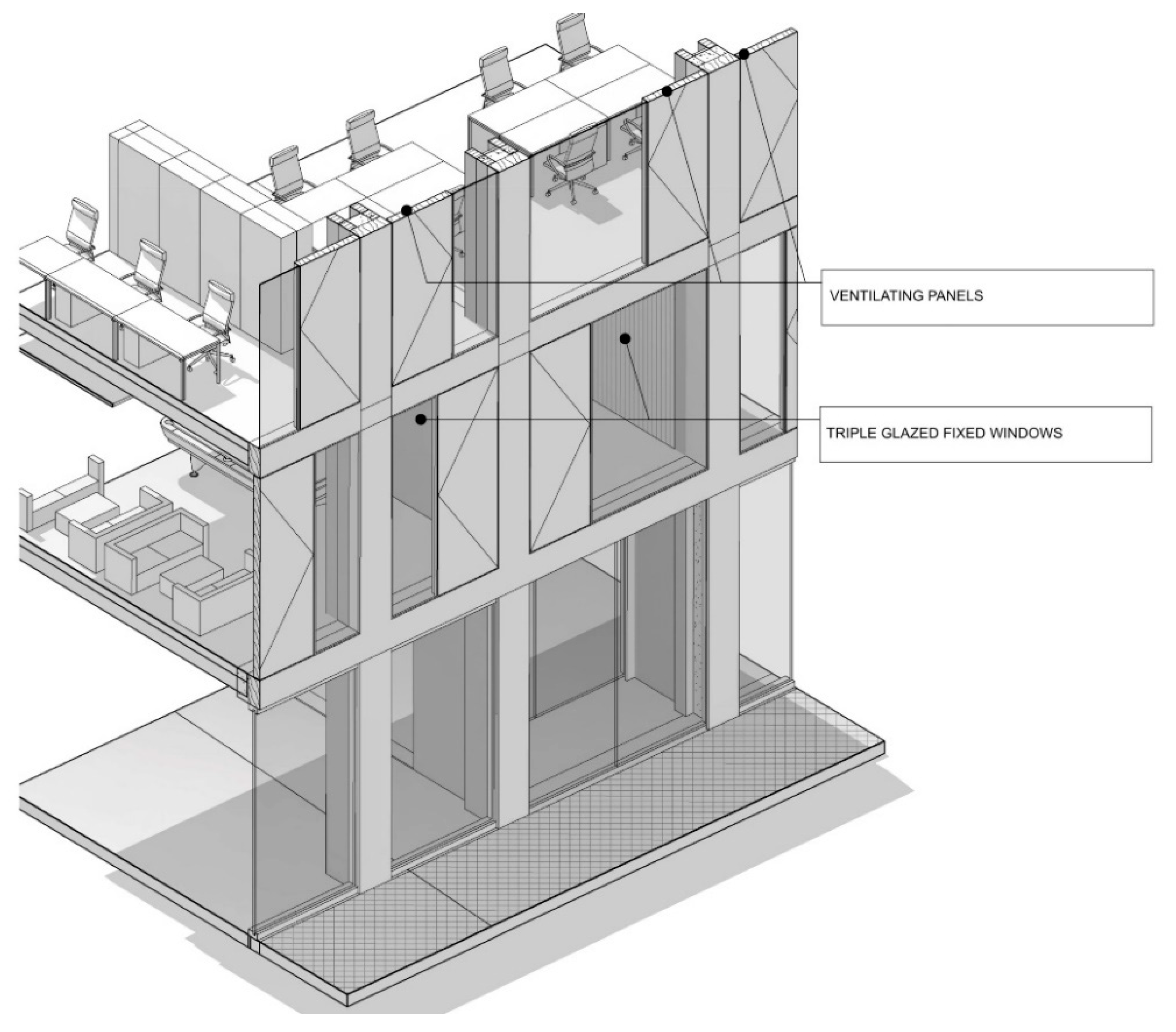
Neither eastern nor northern elevations have excessive sunlight exposure; additionally, wind simulations prove a high potential for stack ventilation or hybrid ventilation systems; hence, the architectonic solution includes windows with vertical aeration slots steered with the use of Building Management System (
Figure 8). The proposed window system consists of a narrow glass panel and an insulated openable timber element. The opening direction varies depending on the window exposure, allowing the use of wind streams from various directions. Window steering will be based on such parameters as external and internal temperatures, humidity and CO
2 level. This type of system is especially indispensable during the Summer months, when the night time should be used for ventilation and cooling, in order to lower the energy requirements for air-conditioning during the day.
Internal glassed atrium forms an integral part of the aerating system (
Figure 9) and acts as a stack chimney when the skylights are open; connection between the elevation windows, aerating panels and the atrium, forms a concept system to be further developed in later design stages as a hybrid ventilation system.
The designed building was set against a reference building and data according to Polish regulations published in the Resolution issued by the Minister of Infrastructure and Construction concerning technical conditions which must be fulfilled by buildings and their location dated 7.06.2019 (
Table 4).
Due to the foreseen energy carrier, the final energy requirements for the designed building could not be estimated in a simple calculation process. It was expected to be a mix of the city-supplied heat and electric energy sourced from alternative sources, including coal. Therefore, primary energy (PE) was accepted as a much better calculation parameter. It was calculated as the final energy multiplied by the non-renewable primary energy input coefficient wi for the chosen energy carrier. For electric energy wi coefficient equals 3.0 and for the Warsaw heating network: 0.79. The total primary requirement for the designed building was estimated at 4,325,859.06 kWh/year and PE ratio at 353.78 kWh/m2y. The total primary requirement for the reference building was estimated at 5,579,475.23 kWh/year and PEref ratio at 497.16 kWh/m2y. Additionally, a reduction of CO2 emissions limited to the area with regulated temperature was estimated and balanced against the reference building. Emission factor for the designed building is 101.7 kgCO2/m2y and for the reference building 143.4 kgCO2/m2y. In comparison to the reference building, alternative design choices used in designed building allowed for better energy efficiency by 28.9%.
All simulations and proposed solutions were prepared as an integral part of the context analysis, and became the conditions for the structural, architectonic and aesthetic choices. This approach allowed existing environmental parameters to be used in order to achieve energy efficient solutions. Concept design proposals indicate the use of active and passive solutions and will undergo further modelling simulations during the next design stages.
3. CASE 2. The Sun and Economic Factors as the Main Analysis Criteria
Case study building is located in the Warsaw new downtown centre, with good access to mass traffic. The site is covered by a valid Master Plan establishing conditions for the Warsaw city skyline, giving a location for a skyscraper ring encircling the city centre. Locations of the dominants are clearly marked and are expected to be included within the city morphology. An additional condition is that above a certain height, the façades should be set off by 6 m from the indicated building line. Front elevations of buildings have to comply with the obligatory building line in 75%. Analysed site conditions indicate a multipurpose office building with the height not exceeding 40 m off east, and a 160-m-high dominant off the west side of the plot. The plan also assumes retail functions accessible from the Ground Floor.
In this case, the client’s brief placed emphasis to achieve a best case usable floor area modelled through efficient use of daylight and energy factors, it also included a shell cost analysis. Therefore, the applied methodology differs from the one presented in Case 1, except for the initial data presented in
Table 1. An algorithmic model in Grasshopper with support of Ladybug Tools was prepared in order to analyse functional effectivity and prepare economic and energy efficiency model (
Figure 10). All energy calculations were based on *.epw weather files and assumed as an annual static calculation including a model of surroundings. Assumed values are annual costs, normalized by Gross Floor Area (GFA). Heating and cooling values were calculated for Ideal Air Loads (hour by hour), assumed values have the energy potential required fulfil the requirement of the set out limitation points: heating (20 °C) and cooling (25 °C). For the simplified room models, only the exterior wall and glazing was set to be non-adiabatic. Calculation assumed such values as occupancy schedule (typical working hours), infiltration rate, lightning, equipment and user heat gains.
Daylight calculations were based on annual data, using Radiance Software and Daylight Autonomy metric (500 lux set point, working plane at 80 cm, annual). Low settings were used (relatively large grid, limited ray bounces amount etc.). The annual sky files generated for calculation were based on *.epw weather files (direct normal radiation data).
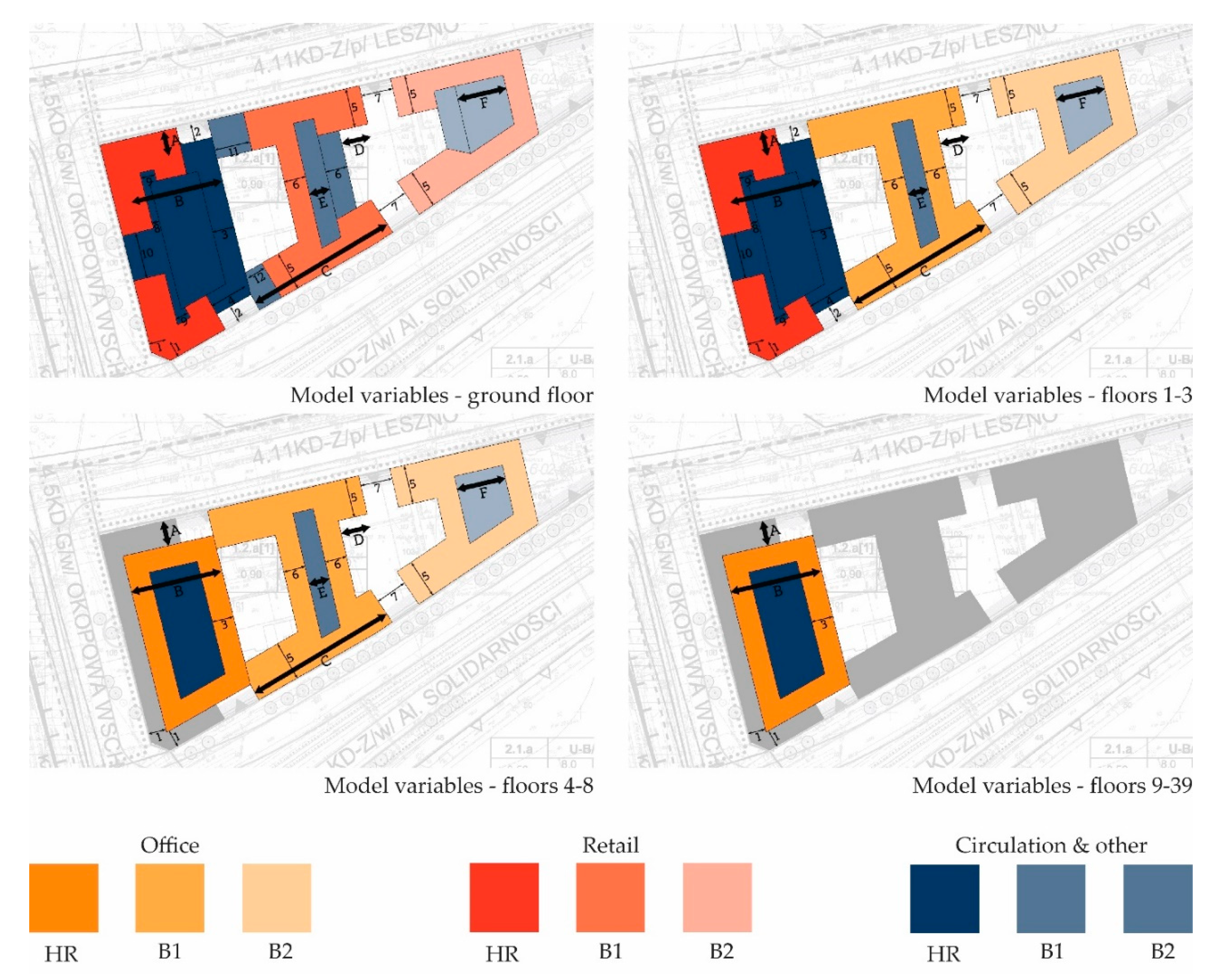
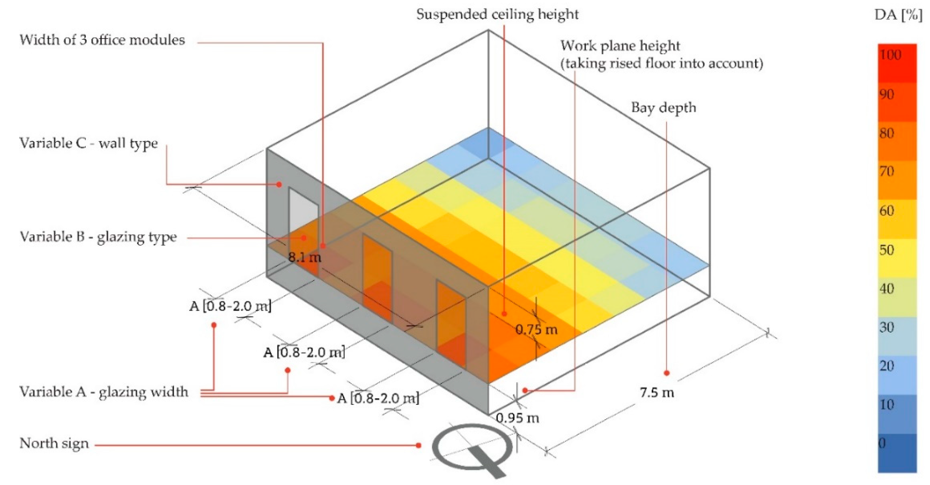
Initial design decisions included reinforced concrete structure, major span: 810 cm, single bay depth level at: 750 cm, and a double bay: at 1350 cm, clear height: 390 cm for the office areas and 585 cm for the retail Ground level. Measurements were based on the Master Plan conditions. Next, the algorithm was created. It was based on the chosen variable parameters presented in
Table 5. Variables are usually decisive where the building zones, different areas and relations with other building elements are concerned. In this phase, some initial assumptions as to the general character of the building and primary massing were established by the designers. These included division of repeatable floors, location of entrance halls, cores, vertical and horizontal communication, office and retail areas. The prepared algorithm allowed to arrive at certain values such as approximate areas or lengths of evacuation corridors. This method was based on a simplified model, but allowed analyses of numerous alternatives at the concept level design and introduction of rapid changes. For example, changes in the depth of the office bays or extension of the building’s podium volume. Some of the parameters were established as constant values (
Figure 10). The choice of parameters depended on assumed use flexibility of the office areas. The function was based on the Master Plan conditions.
Each of the variable parameters was given a jump value of circa 10 cm, which allowed for 285,468,750,000 of possible combinations. The penalty function brought negative value to the algorithm when any of the initially set conditions were not met. In this case, analysis aimed to achieve the largest GFA fulfilling all provided criteria. Each level had to fulfil technical standards including two evacuation staircases, and an adequate number of sanitary areas. The program also set constant values: conference room areas, number and capacity of lifts. Other elements depended on the assumed alternatives: sanitary area depended on the number of foreseen users, area of the lift lobbies and evacuation distances depended on the core’s width.
Two runs of algorithms were used in order to achieve a higher number of alternative solutions. This procedure calculated 14,749 of potential outcomes. They were collected as a summary linear chart of individual genomes which, showed the best case solutions as a colour scheme. The optimization process led to provision of similar objective function values. As the case best solution was not aesthetically satisfactory to designers, the choice went to a more aesthetically acceptable one.
Part of the prepared algorithm simulated shadowing conditions for surrounding urban tissue. All volumes were divided into segments circa 1 m
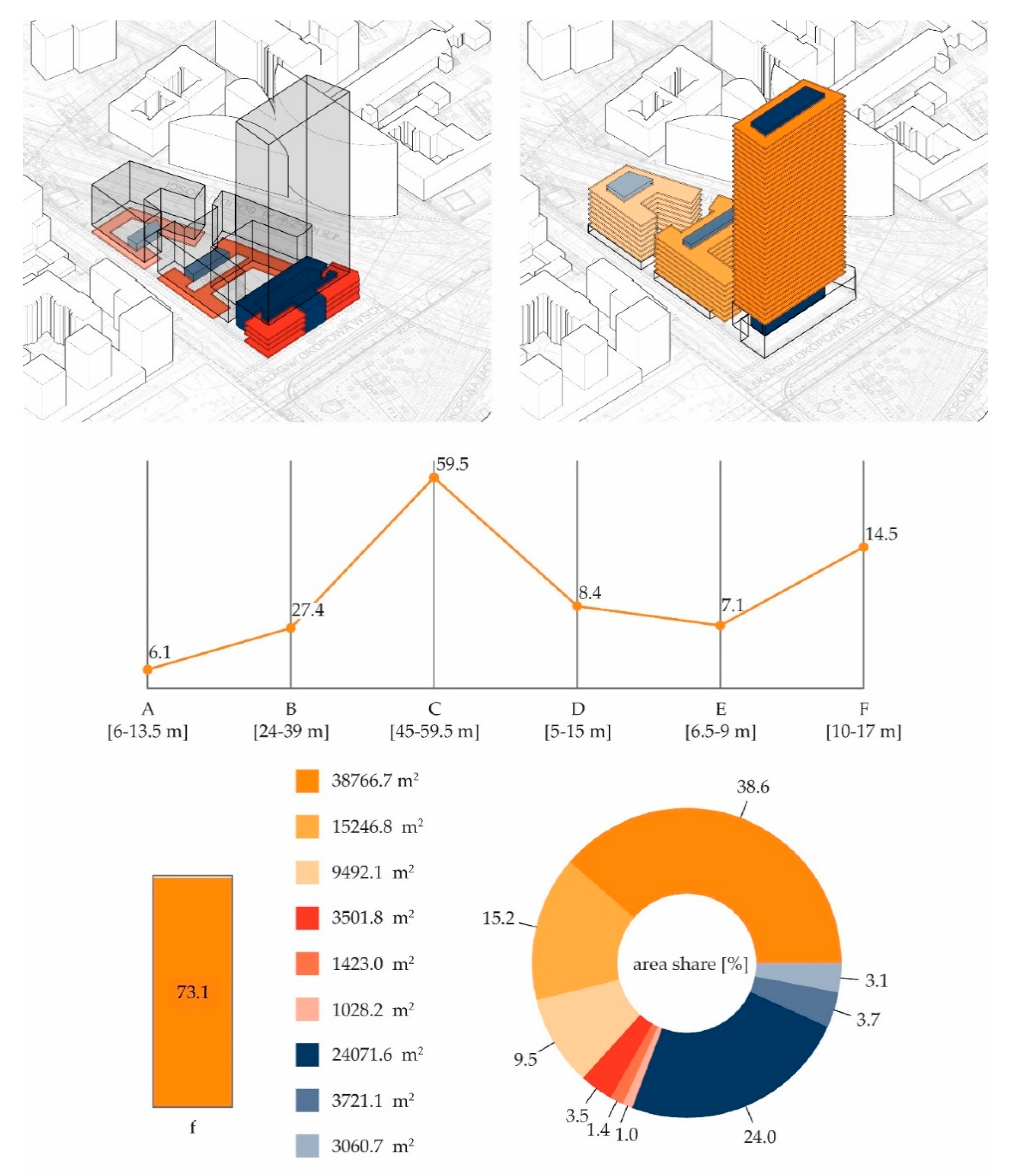
2 and the level of Equinox sun radiation received by each of them between 7 am and 5 pm was analysed. In the next step, all areas which prior to the new in-fill received less than 30 min of sunlight were excluded from further analysis. Following, a similar analysis was made without the new building volume. Simulation indicated which surrounding elevations received 30–90 min of sunlight in this changed conditions (90 min is obligatory in Poland). A simplified analysis allowed to point out which façade areas and on which buildings are the most subject to shadowing. It was noted that a more detailed analysis for every apartment will have to be made during next design phase. Based on the above analysis, the final building volume was chosen and is shown in
Figure 10 and
Table 6.
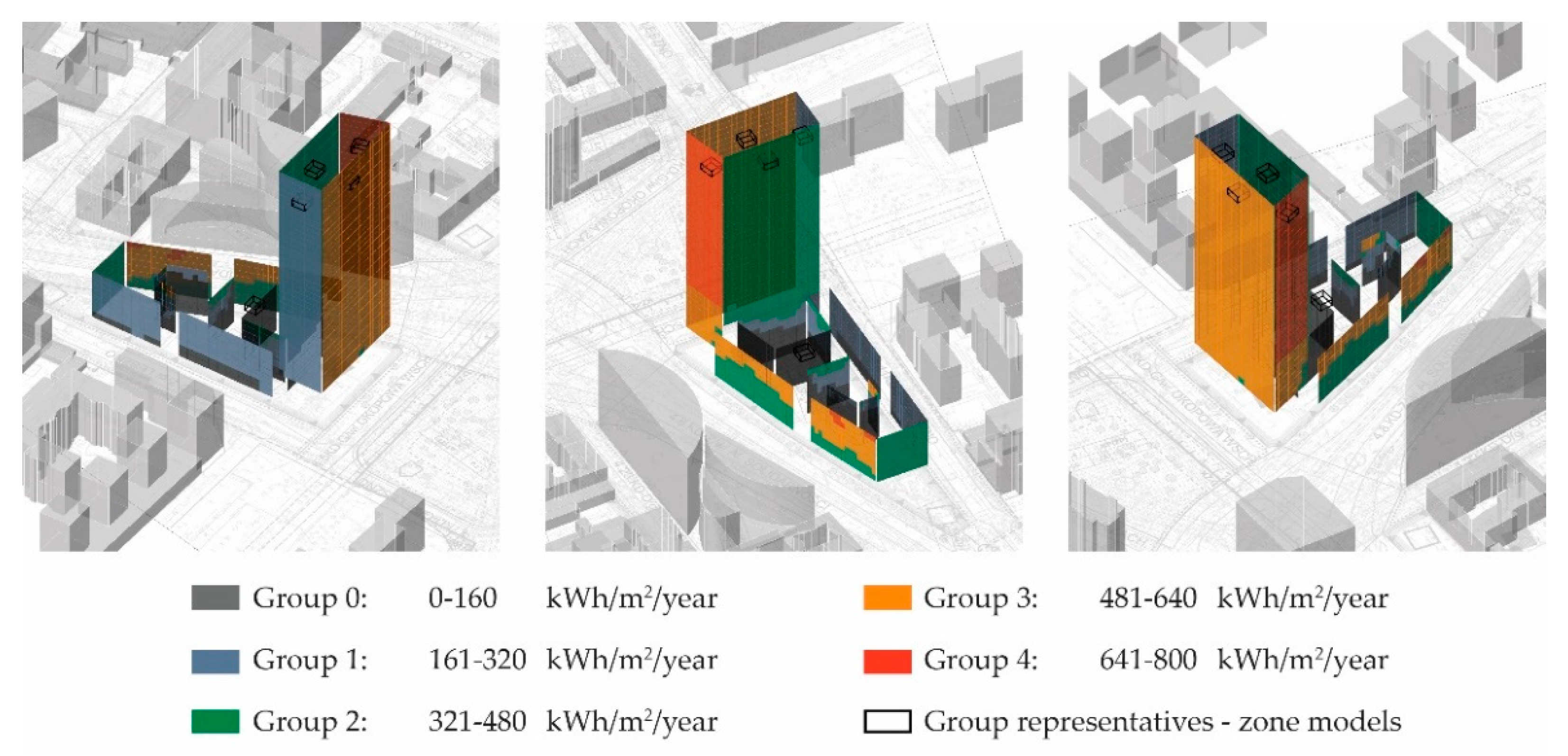
Next, the analysis was dedicated to the measurement of annual sun radiation levels on the new building, and potential heat gains. Both direct and dispersed sunlight data were included. Once more, elevation areas were divided into 1-m
2 elements. This assumption allowed to delimit compact areas, each receiving similar level of sun radiation. The following step was a multi-criteria analysis aiming to find the case best solutions for the building’s envelope. Each of the elevations was divided into 2.7 × 3.9 m modules corresponding to a typical cellular office area and constant height. Based on the sun radiation analysis the volumes were divided into five groups. The aim of the optimisation was to choose adequate building envelope materials, based on the chosen groups. In
Figure 11, a chosen representative from each group is depicted as black elements.
Purchase costs were balanced against utility costs and were limited to the external shell of the building (walls and roof area). Calculations included energy analysis (climatic data, building geometry, number of working hours, internal heat gains, envelope tightness) and daylight levels. Analysis used a multi-criteria genetic optimizer. It was assumed that only a single elevation participates in the heat exchange process, and remaining ones are considered as adiabatic. Assumed annual heating and cooling loads, also electric light requirements, were calculated for each genome. WUT authors included average fees for city heating and electric energies, and fees required to purchase typical curtain wall elements. Construction costs were assumed to be similar for each area and therefore, not included in calculations, as having a marginal impact.
Electric light requirements were based on an annual distribution of daylight levels calculated on the horizontal plane of a working desk (80 cm above floor) and calculation of a Daylight Autonomy (DA). Foreseen energy requirements were differentiated to three lighting zones, each fitted out with a group of LED lights giving 500 lux. An average DA factor was calculated for particular location of each of the zones and used for further calculations of the electric energy requirements. Human preferences, individual screening of windows in some parts of the year were also included. Accepted variables include width of glass elements [A]—80–200 cm, type of glass modules [B], type of wall modules [C]. Due to functional roles, some of the model parameters are treated as constant values (
Figure 12).
Variable values are shown in
Table 7 below.
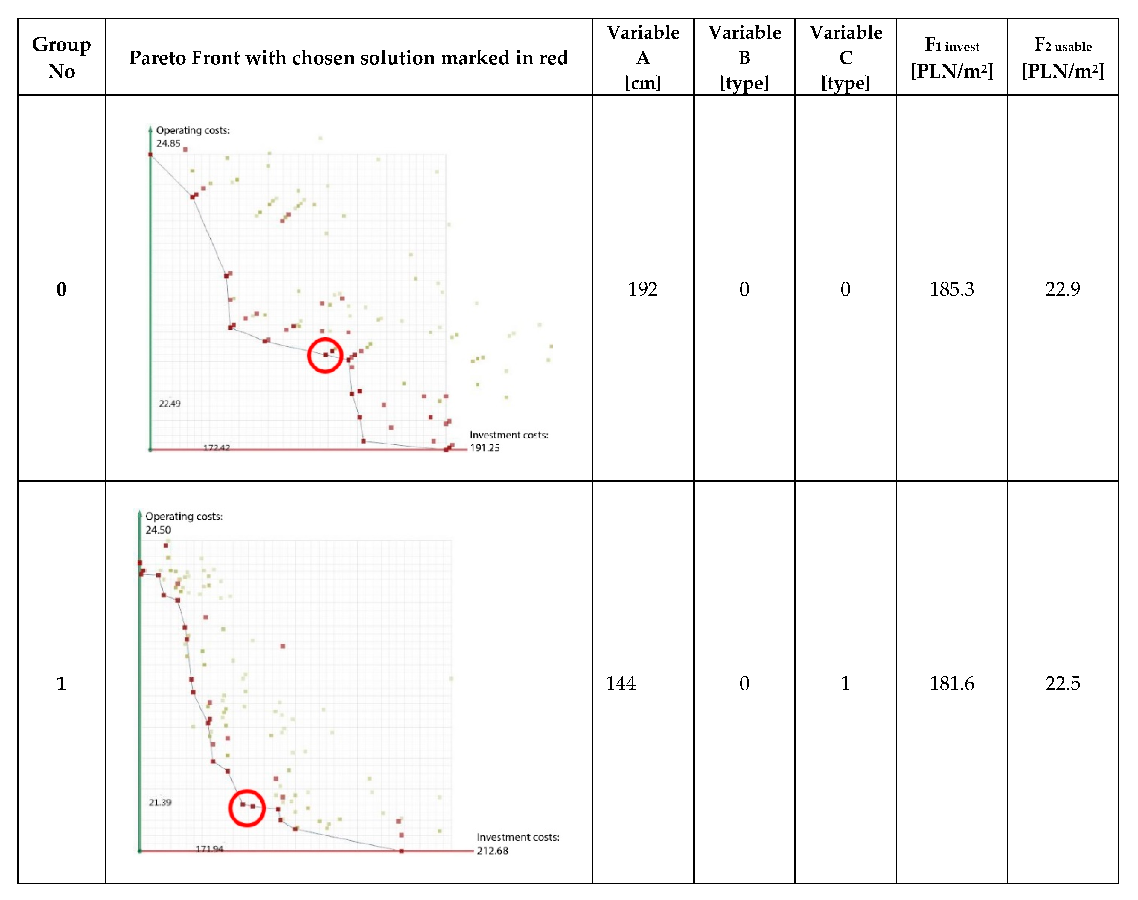
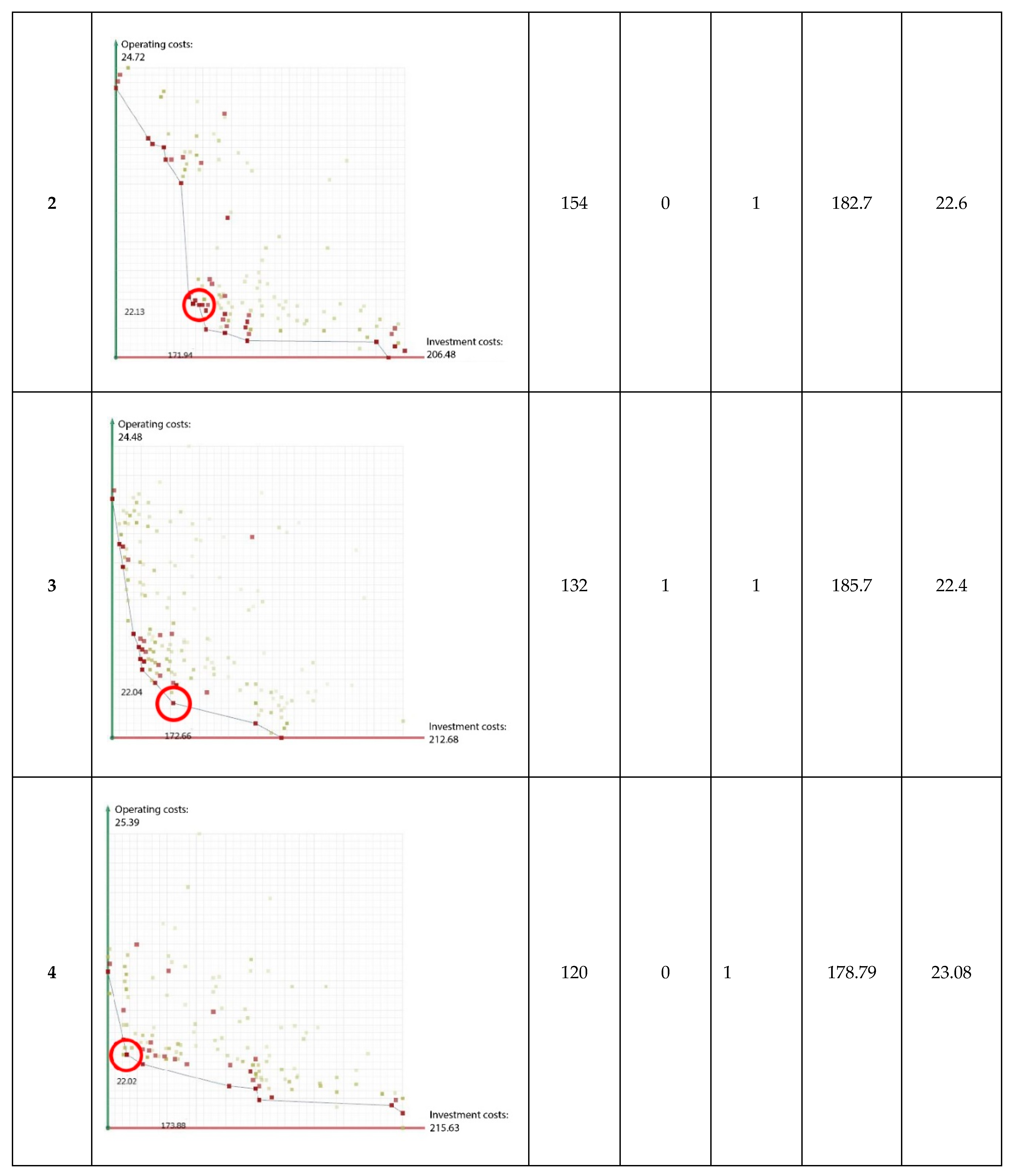
Two objective functions were accepted: the first one aims to minimize the construction costs, the other to minimize exploitation costs. In this case, algorithm was searching for such values which will balance chosen criteria. Analysis gave 1525 variable combinations. As in case of earlier optimization process, the outcomes were saved as spreadsheets and supported the selection of the non-denominated Pareto Front outcomes (
Figure 13) [
33].
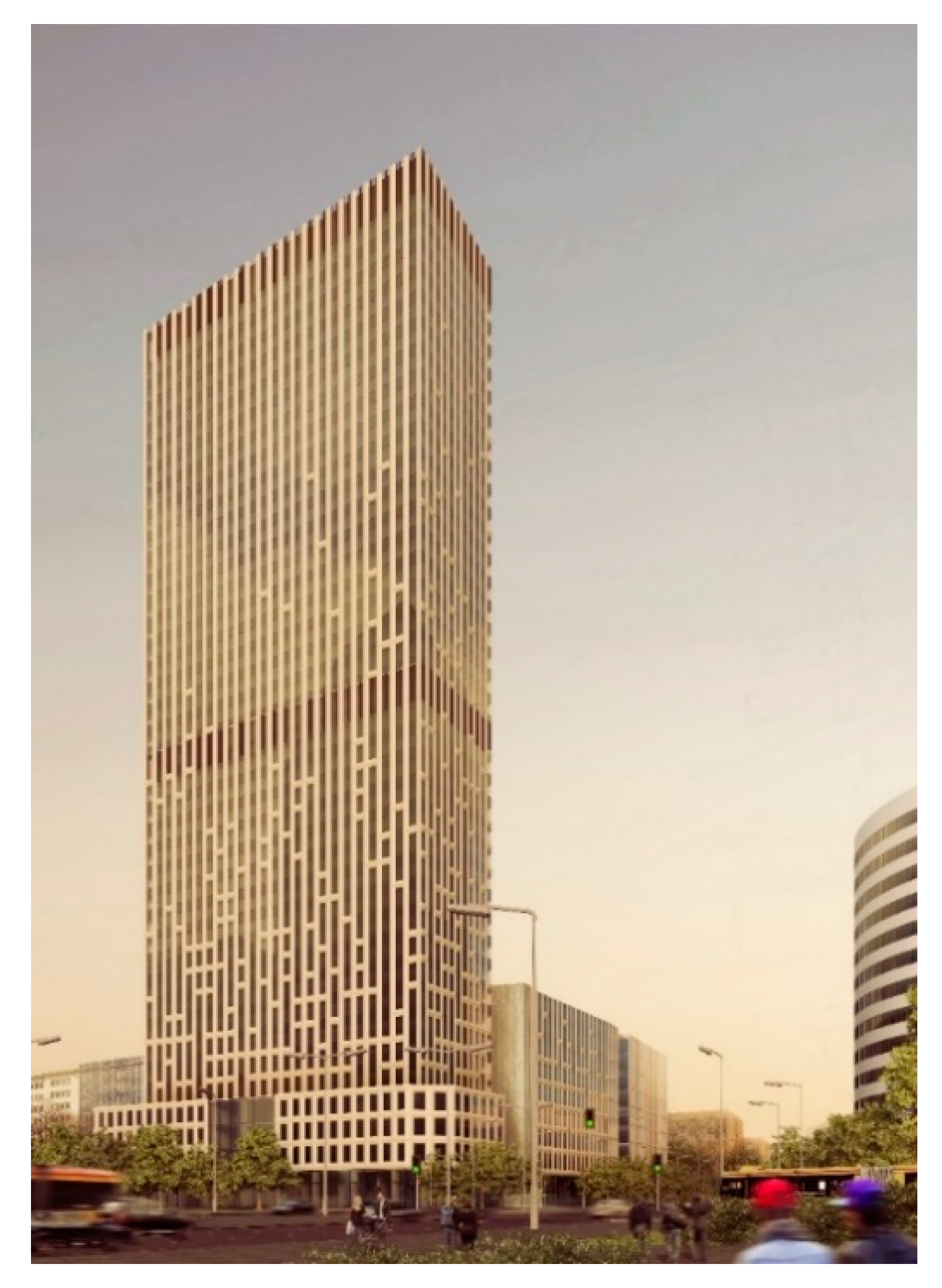
Final design proposal (
Figure 14) is a projection of case best conditions, therefore it should be perceived as an early design concept stage. This proposition proves that initial assumptions, chosen methodology and achieved outcomes can be used as an integral part of the design process and form part of the initial conditions achieving both aesthetic and energy efficient parameters. Nevertheless, this proposition is simply a concept solution which must be developed during later design stages.
The choice was based on the best case solutions found in three categories: low construction costs, low exploitation costs, and genomes which balanced those two values nearest to the starting point of objective function axis in the Pareto Front. Based on the collected outcomes, a single solution was chosen for each of categories and chosen for further analysis (
Figure 15).
4. Conclusions
During the 20th century, early technologies gave birth to architectonic and industrial design masterpieces. The scientific and technological revolution, beside computerisation and automation of industrial processes, also caused over exploitation of natural resources and high emission of pollution. Presently, Sun and Wind energy have become the key elements in the fight to preserve surrounding environment and maintain the balance between natural values and contemporary technological abilities. According to Rifkin, we are facing the third industrial revolution, characterised by the activity of prosumers, where the exchange of alternative energy sources is based on the use of the Internet [
34].
The use of energy analysis has also become an important tool in city planning. More efficient solutions require data on local urban density and energy consumption and possible integration of different renewable energy sources. Both should be updated and environmental consequences analyzed [
35]. The approach presented in this paper has certain limitations. These may be divided into following categories: insufficient and uncertain data followed by inadequate input values, stakeholder expectations and designing team approach.
For example, one of the uncertain data is the energy consumption of elevator systems, particularly difficult to define in high rise buildings where many parameters are involved. There are some studies available prepared by various lift manufacturers, but the actual outcomes depend on the typical trip time varying for different drive systems, and is affected by the number of floors served, motor size, etc. A paper was issued in 2018 [
36], where the authors researched over 700 high buildings, but made rather obvious conclusions with a reference that the building height influences energy consumption due to large areas of external facades and variable external temperatures, various wind turbulences and the actual requirement for lifts. Their line of thinking was that actual impact depends on a specific building occupancy, tenant behaviour and internal system used. A document “Energy-Efficient Elevators and Escalators (E4)” [
37] issued by EC, contains the outcomes of a project covering a thorough analysis of EU elevators also in the tertiary sector. The main identified barrier was insufficient information of the actual electricity consumption in lift systems. The monitoring results were inconclusive and disclosed the importance of the lift’s standby consumption highly influenced by the tenants’ usage pattern. The analysis disclosed that the estimated proportion of standby to overall electricity consumption of lifts in the tertiary sector it represents 41%. When dealing with a concept stage design where many issues has to be assumed, our Team sourced lift energy data based on the information from other Warsaw high-rise buildings, where lifts were metered separately from other appliances. Some information was also found from the Skanska Report from 2018 containing energy analysis in Polish office buildings [
38]. A suggestion was made to the stakeholder that in the following design phases, energy-efficient solutions providing electricity and re-use of energy within building’s grid should be considered. Additional analyses should be provided in the post-construction phase, as proper management of the building systems should yield additional efficiency possibilities.
Another uncertain area is wind analysis. The concept design phase is never very detailed. Hence, in case of wind simulations it is more important to disclose a potential for wind energy and its pattern, rather than to have a detailed outcome. Decisions how to design specifically for wind solutions should be made with the use of more sophisticated software, together with field measurements. Analysis of urban climates should include wind conditions, but existing knowledge has been only rarely applied, as the data is a combination of knowledge from a variety of disciplines. The application area is also uncertain in the planning process both among urban planners, architects and stakeholders. An important input factor of any wind simulation is the wind itself, but in most scientific papers, simple meteorological data from a nearby weather station is usually mentioned. One of the possibilities is the use of the most common main wind directions for the case study area, as they provide an accurate overview of the statistical wind behaviour. The simulation outcomes should be in later design phases compared to the field measurements and accordingly adjusted. Another possibility has been pointed out by Shi [
39], who recommends to perform CFD simulation for each of the eight main wind directions, to be followed by a weighted average wind speed calculations. One of the important areas is simulation of wind loadings distribution on the volume’s height. Due to changing and fluctuating wind parameters, interactive façade solutions connected to Building Management System should be considered during more advanced interdisciplinary design stages.
One of the initial aspects is awareness that particular software tools and scope of analyses depend not on the designing team only, but also on the investor’s level of knowledge and expectations. Especially the aesthetic outcomes presented at the concept stage should be treated more as “in design” process than a final product. More than often, stakeholders require a model which includes architectonic detail which might, but does not have to be followed during the later design stages, or the requirement is for a set of specific analyses based on already existing solutions. Since analysis is made for commercial buildings, very often achievement of a particular label is far more important to the investing party than a set of case best solutions. Therefore, the outcomes have to be balanced between scientific analysis and stakeholder budget.
Parametric approach also brought a new language to the Architectonic design process and changed the designing team approach. It is not a new style, but a tool which allows to discard a rigid application of the building formulas. Architectonic parametrisation can be treated as a simplified mathematical process. Methodology is based on a description of basic geometric characteristics such as the position of the main control points, later on followed by the inheritance of those characteristics by sub-elements. Possibly, this process is similar to an instruction describing assembly of a reductive model, but characterised with a high level of complexity and a replication process of various elements. This tool should be used together with other existing programs including Building Information Modelling (BIM). Influence of new computational techniques used for the optimisation of the buildings’ form is less evident, but a more advanced area of research. Many architects perceive this procedure as dangerous for their profession, as design process is controlled by an algorithm. Nevertheless, the algorithm is formulated by the designer, therefore the final solution is always subject to the creator’s choice and generated from the numerous propositions made by the applied software. Hence, it is much easier to define the best location of a building based on data which includes the sunlight factors which, in the later stages of interdisciplinary design, may be worked upon as efficient heating and ventilation solutions, including natural or hybrid ventilation systems. Without optimisation techniques, it will never be possible to check such a high number of possible alternatives. Designers may give freedom to the searching process, but this process works according to a set of predefined rules. The true meaning of “smart” does not apply to the building elements, but to the design of relations between geometric objects—lines, volumes, curves, etc. These relations are described through mathematic relations controlled by variable parameters. The users can directly interact with the programs through introduction of changes in the geometry, application of rules, definition of relations between model’s elements, or definition of complex forms with the use of algorithms. The essence of the process is not building’s geometry but creation of mathematical and logistic ties between the elements of designed volume. Geometric form is generated as an outcome of those connections and therefore may be easily modified. Further, this process allows modelling through application of chosen climatic or environmental factors supporting sustainable solutions. Depending on the chosen factor or factors determining the base model, we may define the variables required for the building geometry, shadowing or energy sourcing, in turn providing information on Wh/m2 of solar gains, or internal thermal conditions. It is also possible to achieve sustainable optimisation with specialist modules such as Geco®, which cooperate with Grasshopper® or Autodesk Ecotect®. Cooperation between programs based on the climatic data allows for numerous modifications in design solutions already at the concept design phase. Iterations allow adjustments aiming at the most efficient use of steel or use of night ventilation solutions balanced against efficient energy solutions.
As mentioned earlier, the history of numerical simulation in design is relatively long. With the development of software, many tools stopped being used in simple presentations, and currently participate in the creative process. The computer model is not just a geometric description of a building, but a mathematic description of the design process, evolving simultaneously with the projects’ development. This idea of simulations and modelling of dynamic processes connects Architecture with other sciences. Architectonic design, due to its interdisciplinary character, exceptionally quickly adapts new solutions. Contemporary information techniques allow to simulate and analyze consequences of undertaken decisions already at early stages of design. The concept of Information Architecture does not deal with design process only, mainly it discloses the influence of modern technologies on the creation of building volumes dealing with function, form and structural solutions [
40]. The scope and depth of data varies on the choice of input, but there are certain issues which can be pointed out as leading [
41]. The first issue is energy requirements, the main parameter deciding the level of exploitation costs. Hence, it is also the most demanded outcome of energy analyses. Such analysis should not concentrate on energy losses, but also on energy gains. Therefore, energy requirements should be included in all design stages dealing with optimisation of energy use. An important outcome of sun energy simulations are daylight characteristics of building’s internal areas, influencing geometry of building’s envelope, allowing efficient daylight provisions in work zones. Algorithms reflecting the annual path of the sun are more versatile than traditional approaches, and give data on the required level of shading of particular elevation areas. The second issue concerns Computational Fluid Analysis (CFA), currently used quite often in various scientific and design disciplines. Where the building industry is concerned, it concentrates on wind flow simulations. Ventilation system analysis is the most often analysed area, which at later design stages allows to optimise ducts cross sections, type of equipment and geometry of the whole system. A less often used type of simulation is airflow speed distribution in urban areas which has high influence on the user comfort. More detailed analyses include the influence of external wind conditions and surrounding urban morphology on the natural ventilation of designed volumes. The use of energy simulations during design process requires a special interdisciplinary approach. One of the initial aspects is awareness of the context and main development possibilities starting from the concept phase.

 ,
, 


