1. Introduction
Coal mining is important globally for the development of modern industry and the information society [
1], since it provides a cheap, highly efficient, and low-cost energy resource, easily transported to anywhere in the world [
2]. At the same time, the use of coal as an energy resource in the coming decades will be constrained by the environmental problems of its mining, mostly by surface mines, namely the high land consumption of surface mines and the irrevocable disturbance of a significant part of the used land.
The reduction in environmental damage in coal clusters with a predominance of surface mining is possible when expanding the use of the lateral surface mining method, for both low-dipping and inclined (as well as steep) dipping strata. For this method, it is typical to place the overburden in the worked out space, in contrast to the deepening longitudinal mining method, in which the overburden is transported to external dumps, and the surface mine field is constantly deepened and expanded [
3].
Therefore, the main environmental advantage of the lateral mining method is its low land consumption, as a result of maintaining a constant size of the surface mine field and gradually filling it with overburden. As a result, the areas occupied by external dumps and open pits (“lunar landscape”), as well as dust emissions, are reduced. Using draglines to move the overburden from the face zone to the dump zone (internal dump) allows for reducing harmful gas emissions from the dump trucks and diesel fuel costs [
4,
5]. Barden et al., Beutner et al., Rodenberg et al. associated the lateral surface mining method with cross-pit spreaders or cross-pit conveyors, moving the overburden to external (for inclined dipping strata) or internal (for low-dipping strata) dumps [
6,
7,
8].
It is widely believed that the lateral mining method is applicable only for horizontal and low-dipping strata (0–30
°), since its main feature is a final pit depth equal to the depth of the seams [
9,
10,
11,
12]. Zhengao et al. and Mishra et al. distinguished a narrower purpose of the lateral mining method, for low-dipping strata of high thickness. [
13,
14]
In turn, for the surface mining of inclined and steeply dipping strata, the deepening longitudinal mining method is recognized as basic, with the expansion of the boundaries of the surface mine field as coal seams are extracted and overburden is placed in external dumps occupying significant land areas [
15,
16].
A widespread but incomplete technological solutions for reducing the high land consumption of deepening longitudinal method of mining for steeply dipping strata is the adaptation of the relief when filling external dumps in natural hollows, shallows, or slopes [
17,
18]. This makes it possible to partially smooth out disturbance to the relief and to some extent restore disturbed agricultural land, but it does not solve the problem of dust emissions from external dumps and disturbance of the water drains when they are located in lower relief zones.
The dominant opinion regarding the scope of the lateral surface mining method with overburden moving by draglines to the internal dump is the development of low-dipping seams with the dip angle of strata being less than 30°. However, the use of the deepening longitudinal mining method is dictated primarily by the desire to extract inclined and steeply dipping coal seams to the maximum possible depth [
19]. This makes sense with high coal prices on the one hand, and a low concentration of surface mining in the cluster on the other. On the contrary, in conditions of low coal prices and the presence of closely located surface mine fields and dumps, it is necessary to provide for a transition from deepening longitudinal to continuous lateral surface mining methods, with the replacement of overburden external dumping with dump trucks by moving it to the internal dump with draglines, saving the fuel component of transporting costs and reducing occupied land areas and dust emissions.
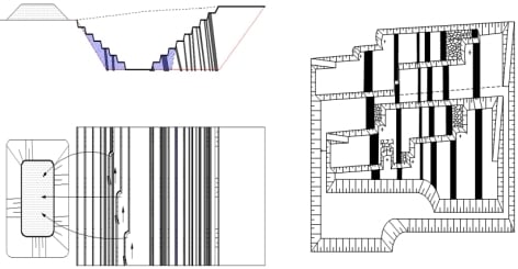
According to the official reporting, at present, the number of surface coal mines in Kuzbass (Western Siberia, Russia) amounts to sixty, with an annual capacity of 194 million t. Of these surface coal mines, 65% carry out mining operations on inclined and steep coal deposits (strata) [
20]. The continuous deepening mining method used in this case is characterized by maximum land intensity—a consequence of the constant expansion of the surface area of mining operations deepen, and the need to fill the external dumps, which also occupy significant land plots and are sources of dust. In 2019 in Kuzbass, the land area occupied by external dumps of surface coal mines counted to 1500 million m
2 (up to 10% of the region’s territory [
21]; the sample of spoiled land by overburden dumps is shown on
Figure 1).
At the same time, the majority of Kuzbass surface coal mines operate on the basis of project documentation, which contains outdated technological solutions dating back to the middle of the 20th century that did not consider the need to reduce land intensity, air and water pollution [
22,
23,
24]. Therefore, at most existing Kuzbass surface mines, overburden is not dumped in the worked-out space of the surface mine field. Meanwhile, the dumping of internal dumps will allow, on the one hand, the reduction in the land area occupied by overburden, and on the other hand, the reduction in terrain disturbances and dust emission.
Technologically, the transition to the placement of dumps inside the surface mine field means the transition from the deepening longitudinal to the lateral continuous mining method, which is accompanied by the refinement of a number of spatial planning solutions that form the organizational mechanism for the mining method transformation [
25,
26,
27].
It should be noted that the surface mining of inclined and steep coal seams strata within the lateral mining method is complicated with the inevitable establishment of a finite depth of the pit [
28]. Therefore, a thorough technological justification for the transition from longitudinal deepening to lateral surface mining method is necessary, with the development of an approach to determining the possibilities and boundaries of its application.
2. Methods
The use of the lateral mining method has its own specific features, which include the presence of strata of complex coal seams with strong enclosing rocks that require drilling and blasting to excavate them. The thickness of the coal-bearing strata of inclined and steep seams in the Kuzbass fields ranges from 200 to 2000 m, which makes it possible to use direct dumping technology at the lower horizons of the quarries [
29]. Taking into account that with a lateral mining method, the length of the working front on the benches is much less, than with a traditional longitudinal mining method, the problem arises in ensuring the safety of surface mining in the limited space of the working zone of the surface mine. This requires an accurate calculation of the parameters of the first-stage pit, mining blocks and the internal dump.
With a small length of the working front on the benches, there is a need for frequent driving of the excavator from bench to bench. Therefore, to reduce this negative factor, it is advisable to use maneuverable surface mining equipment. For the implementation of direct dumping technology in a limited space of the lower horizon of the pit, a variant is possible in which the bench is worked out by a hydraulic backhoe, which carries out advanced excavation of the coal seams, and overburden is excavated by a dragline located in the dump zone.
Taking into account the current provisions for the use of deepening longitudinal and continuous lateral mining methods, we identified the following options for switching to the lateral mining method for the development of inclined and steep coal deposits:
Storage of overburden in a low-profile external dump at various stages of preparing the internal dump. This technological solution is aimed at the positive transformation of mining allotment (creation of a horizontal site) into a useful landscape unit.
Designing “flexible” and combined surface mining methods with the identification of the stages and the procedure for working out the coal seams within the surface mine field with the interchangeability and sequence of application of longitudinal and lateral mining methods [
30,
31].
Adaptation of internal dumping technology to surface coal mining in the sites of closed mine on the basis of combined transport and direct dumping technology and a continuous lateral single-sided mining method.
The development of promising deposits with the division of the surface mine field into blocks with the extraction of a mining layer within each of them. In each layer, overburden removal is carried out according to transport technology with their delivery to the boundary between the face and dump sides, and further transshipment to the dump using direct dumping technology.
Each of these options is characterized by a certain amount of overburden placed in the internal dump and the possibility of using direct dumping technology at the lower horizons of the pit. These important indicators provide a significant increase in the efficiency of opencast mining. In general, to increase the efficiency of developing complex structural deposits with inclined and steep bedding of coal seams is possible with the use of new resource-saving development systems with lateral movement of the front of mining operations.
The following varieties of the surface coal mining system with lateral mining front movement are known: with the construction of the first-stage pit immediately to the design depth of the pit [
32]; with phased immersion of mining operations to the design depth of the pit [
33,
34]; shuttle-layer mining of the surface mine field [
34]; developing a surface mine field with longitudinal-and-lateral movement of the working front [
35].
Taking into account the four above options, the general approach to the transition from a longitudinal mining method with external dumping to a continuous lateral one with internal dumps and block-layer technology can be presented in the following form.
Firstly, the transition of the surface mine to a single-sided lateral mining method is designed with the creation of wide excavation stopes (panels) without the use of elements of the longitudinal system. In the process of developing promising solutions, it is necessary to provide for the minimization of the size of the first-stage pit and the accelerated formation of an internal multi-tier dump to the full depth of the pit according to the peripheral scheme with a minimum distance from the working side. A prerequisite for the transition to a lateral mining method is to give the slopes to the lateral working front on the benches, from the entrance to the pit to the opposite spoil side, which has a horizontal berm for the delivery of overburden by the dump trucks to the internal dump. In the general case, the tiers of the dump may have a slope to provide access to the underlying benches of the working side through the horizontal transport berms of another spoil side.
Secondly, during the construction of the first-stage pit to the full depth of coal seam strata mining, overburden should be placed into an external dump, with the surface mine field divided into the bottom and dump parts. Subsequently, during the following development of the deposit, overburden is placed into the internal dump, while the face part of the surface mine field is worked out by inclined working ledges, and the dump part of the field is formed by inclined dumping tiers. At the same time, the inclination of the working benches and dump tiers is performed in opposite directions, and the cargo transport connection between the working benches and the dump tiers is carried out along horizontal transport berms made in the direction along the deposit strike.
Thirdly, in the face part of the surface mine field, the working side is worked out by inclined benches. The mining front is developed across the strike of the coal seam, while the inclined working benches are cut at an angle so that the beginning and end of the working bench are located on adjacent horizons. This provides transport communication between them. At the same time, there is no need for the construction and constant transfer of sliding exits, and the dump tiers are formed in the dump part of the surface mine field at an angle. To create a transportation connection along the strike of a field between horizons of the same level, horizontal transport berms are built. This minimizes the distance of overburden transportation from the face to the dump zone, since transportation is carried out along the shortest path.
Fourthly, it is necessary to maintain the working space of the pit as unchanged throughout the life of the field. The movement of the face and dump zones of the surface mine should occur synchronously, since the overburden from the face side is laid in the dump part on the same horizon. With such organization of the lateral mining method, the need to divide the surface mine field into stages disappears, and there is no fluctuation in the volumes of overburden and coal extraction over time from the moment the construction of the first-stage pit is completed until the end of mining operations and reclamation of the surface mine.
To substantiate the above-described approach, this article presents the author’s concept of changing the surface mining method for inclined and steep coal seams.
The use of a block-and-layer continuous lateral mining method with combined transport and direct dumping technology consists of preliminary dividing the surface mine field into separate blocks that are developed sequentially. Moreover, the development of the priority block is carried out according to a deepening longitudinal mining method with transport technology and moving its overburden volume to an external dump. Then, the next block is worked out according to the same technology as the first one, but the overburden is transported to the worked-out space from the first block. This variant of block technology is characterized by most of the drawbacks of traditional technology, in particular, the entire rock volume is placed in an internal dump using transport technology.
To modernize the block technology of surface mining, the block-and-layer technology of the continuous mining method is proposed, characterized by, during the construction of the first-stage pit, the mining of the block and its horizontal layers being carried out according to the layered-areal technology, which ensures the extraction of all seams of the strata from its hanging side.
One of the most important elements of the lateral mining method is the first-stage pit, which creates the conditions for internal dumping. The first-stage pit is constructed according to the layered-areal transport technology, which consists of sequential field development in the boundary contours of the first-stage pit in horizontal layers (
Figure 2).
It should be noted that if for the construction of the first-stage pit, as well as for excavation of coal, hydraulic backhoes are used, and then draglines are used for the direct dumping part of the formation of internal dumps.
The parameters of the first-stage pit are determined in conjunction with the parameters of mining blocks. To display this relationship in
Figure 2 the following notation is used:
Lfqb–length of the first-stage pit along the bottom, m:
where
Lb is the length of the excavation block (determined by the height of the horizontal layer along the bedrock (
hl) and the elevation angle of the road
(i, ‰):
Krd is the road development coefficient (1.2–1.3, depending on the width of the read);
Hq is the designed pit depth, m;
γw is the general slope angle of the working side of the internal dump, degrees
γf is the the angle of finalization of the side of the pit, degrees.
Le is the exit length, m:
where
Lfqt is the length of the first-stage pit on top, m:
where:γs is the slope angle of the side of the pit from the soil of the strata, degrees;
γws is the slope angle of the working side of the pit, degrees.
The layers are worked out in the block by a mining and transport complex, consisting of hydraulic backhoes and rope shovels in combination with the dump trucks. When switching to internal dumping, the block is mined using combined transport and direct dumping technologies. The rock from the worked layer moves under the slope of the block into the zone of dragline operation, which forms the tier of the internal dump with placing of the rock above the level of its standing, as well as part of the overburden that did not fit the capacity of the first tier is re-excavated to the upper dump tier by the dragline (
Figure 3).
The numbers in
Figure 3 are the layers’ numbers in the blocks to be serially excavated. In this case, the cross section of the pit’s working zone will be characterized by the width of the pit along the bottom and top, as well as the finalizing angles of the open pit sides (
Figure 4).
Sections A-A and B-B in
Figure 3 and
Figure 4 relate to the mining development plan (
Figure 5) for the construction of the first-stage pit and the further development of the strata of steep coal seams according to a block-and-layer continuous lateral mining method (with filling of the worked out space by dumping internal dumps). The parameters of the mining method in the cross section include the following:
Bfsb—the width of the first-stage pit along the bottom, m. Its maximum value is:
The working Equation for calculating the width of the first-stage pit on top
Bfst, m:
where γs is the slope angle of the side of the pit from the soil of the strata, degrees;
γr is the slope angle of the side of pit from the roof of the strata, degrees;
Taking into account that with a lateral mining method, the length of the front of work on benches is much less than for traditional longitudinal mining methods, the problem arises in ensuring the safety and organization of mining in a limited space of the working zone of the section. Under these conditions, the use of direct dumping technology when working out the lower horizon of a surface mine field becomes difficult. To implement this possibility, it is necessary to fulfill the condition:
where Lfront is the length of the working front on the lower horizon, m;
is the safe distance according to the conditions of drilling and blasting (minimum 300 m), m;
WPdr is the width of the platform for dragline, m;
Btr is the width of the transport berm, m;
Lbb is the blasted block length, m.
The length of the mining front on the lower horizon depends on the capacity of and the thickness of the coal seam strata, the boundary stripping ratio, the coal content of the strata, the balance reserves of the seams, and the number of seams accepted for mining with the formation of a single common horizon.
When mining a coal seam strata of complex structure and occurrence, the length of working front on the lower horizon becomes equal to the maximum width of the first-stage pit along the bottom (Bfsb) (5).
When mining part of the strata, the length of the pit at the lower horizon decreases. Thus, the possibility of direct dumping technology is excluded with . So, when using dragline ESh 11.75 (made in Russia, bucket capacity is 11 m3, boom length is 75 m), the minimum length of working front on the lower horizon will be 620 m. The thickness of the coal-bearing strata of inclined and steep deposits in Kuzbass surface mine fields exceeds 250 m, which makes it possible to use direct dumping technology at the lower horizons of the section.
The development of layers of the first-stage pit is carried out by hydraulic backhoes in a complex with dump trucks. Fertile and potentially fertile layers (sediments) are separately stored on board the first-stage pit. Then, they proceed to the development of bedrock (after drilling and blasting) with the extraction of coal in the first-stage pit (which is shown on
Figure 5). Subsequently, the fertile and potentially fertile soil layer is restored on the dump part of the pit (internal dumps in the lower part of
Figure 5). As the working front progresses, the opening of the benches is carried out by sliding exits in the barren of coal zone (left side of
Figure 5).
The hydraulic backhoe moves from the exposed flank of the stope to the opposite one, across the strike of the coal seam strata [
36]. The overburden is transported to a temporary external dump formed on the pit side through a trench worked through the sediments, and the coal is delivered in a similar way to the places of its processing and storage. After working one stope over its entire length, equal to the cross section of the coal seam strata, surface mining is deepened while the mining cycle is repeated. Thus, work is ongoing to the final depth of the surface mine.
After completion of the construction of the first stage-pit, the remaining part of the surface mine field is mined in blocks along the lateral continuous mining method. Following the advancement of the working front, reclamation is carried out.
The advantages, presented in
Figure 3,
Figure 4 and
Figure 5, of this technological scheme of a block-and-layer lateral mining method are that it does not have operational losses of coal, since exits do not cross the seams, so the additional losses can be avoided. Additionally, when stripping the surface mine field with sliding exits, there are no additional violations of the earth’s surface, since the exits are initiated taking into account the fact that the working front approaches from the hanging side of the coal seams strata.
The use of the lateral mining method in the conditions of Kuzbass has its own specific features, which include the presence of strata of complex coal seams with strong enclosing rocks that require drilling and blasting to prepare them for excavation.
A feature of the technology in the lateral development of the working front during mining of coal deposits is the presence of the horizontal base of the dump and lateral planes from undisturbed array. Moreover, the width of the base of dump is equal to the width of the bottom of pit, and the width of dump at the level of surface corresponds to the width of pit on top. Thus, the internal dump is formed in a clamped environment. The filling of the dump is done in tiers, i.e., dumping is carried out by draglines on all tiers of internal dump (
Figure 6).
To determine the parameters of the internal dump, a rigid relationship should be adopted between the volume of overburden rock in the face zone and the capacity of internal dump, i.e., the capacity of internal dragline-made dump is equal to the product of the volume of overburden rocks in the face side of the surface mine field and the rock loosening coefficient. In this case, the volume of overburden and coal in the face zone (
V) is, m
3:
where
Hq is the face zone height (design pit depth), m.
The volume of coal (
Vc) in the face zone (m
3), is equal to:
where
Kcb is the coal-bearing coefficient (the ratio of the total normal thicknesses of coal seams to the normal thickness of the strata).
The volume of overburden, taking into account technological coal losses, transferred to the internal dump, is equal to:
where
Kl is the coal losses coefficient (at the Kuzbass surface coal mines, for inclined and steep seams with a thickness of individual seams of 5–25 m:
Kl = 0.03–0.05).
Direct dumping of an internal dump with a continuous lateral mining method also has its own characteristics. The base of the dump is a horizontal plane, which provides it with good stability. The analysis of geological and mining conditions of surface coal mining of inclined and steep seams in Kuzbass showed a relatively small length of the internal dump along the bottom of the pit–within 100–900 m. Therefore, the internal dump is formed in the worked-out space, limited on the flanks by the sides of the pit, which, with a short dumping front, contributes to its stability (
Figure 7).
In
Figure 7, the following designations are accepted:
Hd—the height of the dragline-made dump;
Ht1, Ht2, Ht3—heights of dragline-made dump stages;
A is the width of the dump stope;
Hdd—dragline discharge height;
γgd–general slope angle of the dump;
αdt—the slop angle of the dump tire. Applying the methodology of mining and geometric analysis of internal dumps, developed by Kuzbass researchers in international cooperation [
27,
29], we get:
To reduce the volume of Equation (12), we take:
where
Kloos is the loosening rate of overburden in the dump.
Along with internal dumping with filling up the worked-out space, the block lateral mining method presented in this article allows reclamation of internal dumps as they are being dumped.
Reclamation technology is carried out in the following sequence. A potentially fertile layer is poured after moving the dumping front to the surface of bedrock in the dumping tier, and the soil layer is laid on top of it and their addition is carried out in the following order.
The bulldozer moves the surface layer to the bulk, thereby forming it along the working front, which then develops a wheel loader for trucks with transportation to the surface of the internal dump (shown in figure by the arrow). At the same time, a potentially fertile layer is developed at its full thickness by a shovel with transportation by trucks to the surface of bedrock. Storing this layer on the surface is carried out similarly and in the following sequence. The dump truck is unloaded perpendicularly to the edge line of the slope of dump, forming a series of small rock piles, which are then moved and dumped under the slope by a bulldozer.
Reclamation is carried out after the advancement of the overburden and mining front works. After mining the surface mine field, the residual pit is filled with rocks of the external dump formed during the construction of the first-stage pit with the subsequent application of a potentially fertile layer of rocks and a fertile layer.
4. Discussion
When analyzing the first-stage pit parameters, the volumes of overburden placed in the dumps, and the area of the land plots occupied by external dumps, it is obvious that the continuous lateral mining method has many advantages over the deepening longitudinal method, in creating conditions of reducing environmental damage and transportation costs.
First, the linear dimensions of the surface mine field for the continuous lateral surface mining method are smaller than for the deepening longitudinal method. Therefore, the length of the first-stage pit along the bottom and top is almost equal to the length of the block being removed (
Figure 9), while for the deepening longitudinal mining method, it is in 2.5–3 times higher. Is is very important to note the slower increase in the length of the surface mine field as the dip angle of strata increases. If, for the continuous lateral surface mining method, the length of the pit for strata with the dip angle of 80% is 1.8 times higher than for strata with an angle of 50% (
Figure 9), then for the deepening longitudinal method, this difference is 3–3.5 times, based on mining geometric features.
The key difference between the linear dimensions of the surface mine field in the continuous lateral surface mining method from the deepening longitudinal one is a slight increase in its length and width depending on the increase in the pit depth (
Figure 9 and
Figure 10). If, as the depth of the pit increases with the deepening longitudinal mining method, its length and width increase by 1.8–2.5 times, then for the lateral mining method, as follows from
Figure 9 and
Figure 10, the increase does not exceed 10%.
As a result, the smaller size of the surface mine field in the continuous lateral surface mining method leads to a smaller amount of overburden placed in the dump. From the data presented in
Table 2, it follows that with a three-fold increase in the depth of the pit (from 100 to 300 m), the overburden volume with the deepening longitudinal mining method increases by 1.8 times, whereas with the deepening longitudinal method, this increase would be twice as much.
Secondly, along with smaller overburden volumes in the deepening longitudinal mining method, its placement is carried out mainly in the internal dump, the height of which can be equal to the depth of the pit (
Table 2). In this case, only part of the overburden of the first blocks is placed in the external dump. Therefore, despite the inevitable dumping of the external dump, with the lateral mining method, its volumes are less than with the deepening longitudinal one, by more than 10 times (
Figure 11). Consequently, the land area occupied by the external dump with the continuous lateral surface mining method is 6–11 times less than with a longitudinal one. Along with this, the height of the external dump, determined by the dump slop stability conditions, is also 1.5–2 times less for the continuous lateral surface mining method than for the continuous lateral one, as a result of a smaller overburden volume laid in one or two tiers of 30 m in height.
It was found that the influence of the horizontal thickness of the strata (the width of pit bottom) on the height of internal dump is not significant. So, with an increase in the horizontal thickness of the strata by 100 m, the height of dump increases by 0.8%; the same is true for any values of the height of the face zone and the coal-bearing capacity of strata. On the contrary, the coal-bearing capacity of strata, characterized by the respective coefficient, significantly affects the height of the internal dump. An increase in coal-bearing capacity of strata by 10% leads to a decrease in the height of the dump by 8%. For practical calculations when designing the technology, it is proposed to use the dependences of the dump height on the depth of pit and the coal-bearing coefficient, which determines the dumping of multi-tier dumps (up to 5 tiers) with a total height of no more than 200 m.
As a result, the smaller surface area of the external dump in the continuous lateral mining method leads to significantly less dust emission, in comparison with the deepening longitudinal method. The data in
Figure 11 show that dust emissions from an external dump with the lateral mining method are 5–9 times less than with the deepening longitudinal method. Moreover, as the pit depth increases from 100 to 300 m in the first case, dust emissions remain almost constant, and in the second case, they increases by 1.4 times, reaching 12.5 t per year for a surface mine with annual capacity of 6 million t and an strata dip angle of 80%.
Thus, the calculation results clearly indicate in favor of reducing environmental damage during the transition to the continuous lateral surface method of mining of coal seams of inclined and steeply dipping.
Thirdly, an economically continuous lateral mining method is also more advantageous than the deepening longitudinal one, since its main technological difference is the movement of overburden by draglines into the internal dump. This means replacing the dump trucks with draglines, while the number of dump trucks used in the deepening longitudinal mining method (5–13, depending on the annual capacity and depth of pit) is higher than the number of draglines used with the continuous lateral mining method (3–11), due to the higher productivity of the latter (
Table 3). At the same time, despite the higher cost of selected draglines compared to dump trucks (in 2.5–3.5 times), the costs of their maintenance are much lower than dump trucks, and the service life (30 years or more) is significantly higher compared with dump trucks (7–9 years at maximum load).
Comparison of diesel fuel costs for dump trucks and electricity for draglines when moving overburden (
Table 4—physical measures,
Table 5—monetary estimates) indicates the advantage of the latter by 2.5–2.7 times, depending on the depth of the pit and its annual capacity. It is important to note that it is impossible to completely refuse the use of dump trucks in the continuous lateral method, since the removal of the overburden of the first blocks to an external dump is required. However, at the same time, one dump truck with the smallest carrying capacity (in our case, Komatsu HD1500-8, 172 t) is enough; the range of transportation of overburden to an external dump will also be minimal (less than 3.5 km in our case).
As a result, the cost of overburden transporting with the continuous lateral surface mining method is 2.4–2.7 times lower than with the deepening longitudinal method (depending on the depth and annual capacity of the surface mine), as shown in the data in
Figure 12.
Thus, there are environmental and economic advantages of the transition from the deepening longitudinal to continuous lateral surface mining method, with the characteristic use of block extraction of rock mass for inclined and steeply dipping strata. The use of block-layer technology avoids the main limitation of the lateral mining method, namely applicability only for low-dipping strata.
At the same time, a number of limitations of the application of mining method presented in the article should be highlighted, connected with the special deposits for which the transition from deepening longitudinal to continuous lateral mining method is impractical:
Deposits of low-quality coal (high ash content and low calorific value), especially with seams of low average thickness (less than 5 m). It is highly probable that a change in the mining method for such deposits from deepening longitudinal to continuous lateral will critically decrease investment efficiency in the replacement of dump trucks with draglines.
Coal deposits with a high density of tectonic disturbances, leading to the presence of large zones barren of coal. In this case, a significant number of blocks in several layers will contain only overburden, the extraction of which will not be accompanied by coal mining. This will greatly complicate the placement of the internal dump in the worked-out space.
Deposits of coal, before the completion of the development of which is less than 10 years. This is due to the need to build a first-stage pit for a continuous lateral mining method, which, together with reaching the maximum volume of coal production using block technology, can take up to two thirds of this period.
Coal deposits in seismically active zones (more than two earthquakes with magnitudes more than 4 points on the Richter scale per year). This is due to the danger of violations of the tracks for the passage of draglines inside the surface mine field.
At the same time, these restrictions are associated with specific deposits, which make up a small part of the currently developed coal deposits by surface mining in the world.


