Review of Dynamic Positioning Control in Maritime Microgrid Systems
by
 , , , and
Mojtaba Mehrzadi
1 ,
,
Yacine Terriche
1,
Chun-Lien Su
2,* ,
,
Muzaidi Bin Othman
1,
Juan C. Vasquez
1 and
and
Josep M. Guerrero
1
1
Center for Research on Microgrids (CROM), Department of Energy Technology, Aalborg University, 9220 Aalborg East, Denmark
2
Department of Marine Engineering, National Kaohsiung University of Science and Technology, Kaohsiung City 80543, Taiwan
*
Author to whom correspondence should be addressed.
Energies 2020, 13(12), 3188; https://doi.org/10.3390/en13123188
Submission received: 26 April 2020
/
Revised: 27 May 2020
/
Accepted: 13 June 2020
/
Published: 19 June 2020
(This article belongs to the Special Issue Microgrids 2020)
Abstract
:For many offshore activities, including offshore oil and gas exploration and offshore wind farm construction, it is essential to keep the position and heading of the vessel stable. The dynamic positioning system is a progressive technology, which is extensively used in shipping and other maritime structures. To maintain the vessels or platforms from displacement, its thrusters are used automatically to control and stabilize the position and heading of vessels in sea state disturbances. The theory of dynamic positioning has been studied and developed in terms of control techniques to achieve greater accuracy and reduce ship movement caused by environmental disturbance for more than 30 years. This paper reviews the control strategies and architecture of the DPS in marine vessels. In addition, it suggests possible control principles and makes a comparison between the advantages and disadvantages of existing literature. Some details for future research on DP control challenges are discussed in this paper.
1. Introduction
In the offshore industry, dynamic positioning systems (DPSs) are widely applied; this can be seen in pipe laying, offshore wind farms, and drilling rigs, for example. As a result of the restrictions on the use of anchor in deep water, a vessel has equipped by rudders, propellers, and thrusters; these are used to automatically keep its position and heading stable and safe from environmental disturbances such as waves winds and sea currents [1]. Historically speaking, the DPS was first used in the 1960s with the aim of controlling the motion of vessels in three horizontal degrees of freedom, such as sway, surge, and yaw. The single-input-single-output (SISO) and the proportional-integral-derivative (PID) with a low pass filter control systems were used. Unfortunately, the PID control system caused a phase change that affected the stability of the system [2]. Balchen and his colleagues used the Kalman filtering techniques, stochastic optimal control theory, and more advanced control algorithms to improve the DPS application on the vessels. This was based on the assumption of kinematic equations [3,4,5,6,7]. However, the results showed that the equations of motion were linear in a series of predetermined fixed yaw angles, and the stability of the DPS could not be guaranteed. The study in [8] introduced the nonlinear control rules of universal identical asymptotical permanency based on the backstepping method where environmental disturbances are not considered. However, the ecological disruption caused by sea conditions is dynamic and could not be unnoticed. The passive nonlinear observer (PNO) that consists of the bias formal approximation of low-frequency position was proposed to measure the velocity of the vessel during the movement, and wave filtering to decrease the quantity of adjusting parameters [9]. The performance of their methodology used to design the proportional-derivative (PD) control rule, for the output feedback evaluations of the dynamic position system, was investigated in [10]. In this experiment with a vessel model, the observer filters eliminate the noises from the measurements of Ship position velocity by designing a PD controller that is gradually changing due to environmental disturbances.
New control techniques have been Constituting an advanced model of intelligent behavior, and computational methods have been developed to support them. An adaptive nonlinear PID controller is considered to decrease the deviation of vessels from the wanted position while environmental disturbances cause unexpected sudden changes of positions [11,12]. The research presented in [13] proposed an adaptive observer for dynamic positioning on the output of the feedback controller to approximate the remotely operated underwater vehicle (ROV) speed and uncertainties of parameters. Moreover, it has proposed a linear Kalman Filter (LKF), an Extended Kalman Filter (EKF), an adaptive Kalman Filter, and a passive nonlinear observer-based mathematical model on the ROV Minerva. Besides, an adaptive controller has been developed to estimate the nonlinear DPS parameters by adaptive fuzzy logic theory in [14,15,16,17,18,19]. The study in [20,21,22,23] is presented a neuro-fuzzy algorithm, which includes a fuzzy control-based neural network algorithm (NNA) so that the basis for the fuzzy rules and membership function can be created during the network learning process. By applying the NNA and it’s setting, the self-regulation of the membership functions is desirable. In addition, in fuzzy and neural network algorithms, the mathematical model does not consider the deriving controller due to timesaving consideration.
In [24], the DP technology, DP vessel mathematic model, DP controllers and supervisors, thrusters allocation, as well as the hybrid control of DP vessels experiment results were reviewed. To emphasize the requirement of further investigation in this filed, the research presented in [25,26,27,28,29] was focused on hybrid control techniques and operation in DP vessels from calm to extreme sea conditions. It analyzed a hybrid control method for switching between linear or nonlinear controls in maximum operating conditions. In this control method, the nonlinear controller uses an independent scale for switching control to ensure overall system stability and prevent snoozing.
Intending to further enhance control performance, researchers in [30,31,32,33,34,35] proposed the model predictive control (MPC). These types of literature are compared to the advantages and disadvantages of the MPC for typical non-linear control applications in DP control problems with other conventional algorithms. Especially, in advanced vessels such as cable laying and shuttle tankers, more sophisticated energy management systems are applied to predict the power demand, route scheduling, and thrust allocation to keep the position of the vessel by using the DP control technique. On the other hand, the power management system (PMS) which was applied in [36,37,38,39,40,41,42,43,44,45,46,47,48] for controlling of power generators, blackout prevention, power limitation, load sharing, and load shedding. Without a doubt, the DP control is issued according to the information about available power from the PMS to set the desired pitch/rpm load demand to allocate power for thrusters systems.
This paper presents a review of the advantages and disadvantages of the DP control strategies, which have occurred over three decades of investigation and improvement on marine vessels. This literature is divided into five sections. Section 2 presents the DP system models and components in marine vessels. Moreover, throws the light on the DP control classifications are and provides a summary of the vessel models. Section 3 discusses different control strategies, including Kalman filter, model predictive control, fuzzy logic control, neural network, and an adaptive sliding mode with finite-time observer-based control in DP vessels. Finally, the challenges facing the traditional DP controls and further study are discussed as a conclusion in Section 4.
2. Marine Vessel DPS Description
2.1. Overview of DPS Applications
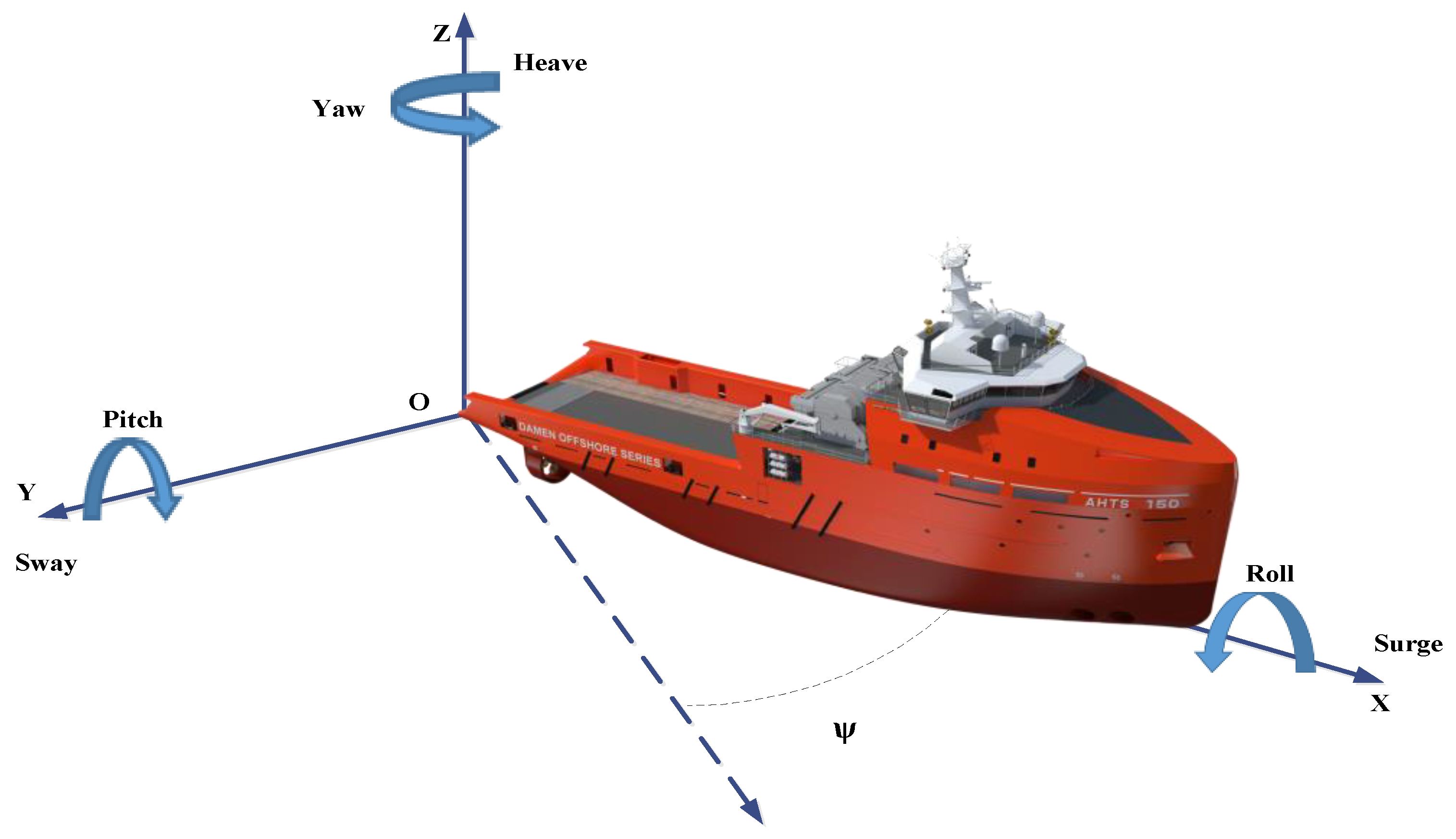
For many offshore activities, it is essential to keep the ship’s position and heading stable. The DPS automatically controls the position and heading of a ship by using thrusters that are persistently dynamic to face the environmental forces induced by waves, currents, and wind. Environmental disturbances try to move the vessel from the desired position while the DP controller automatically compensates for those forces and keeps the ship in a stable position by using its propellers and thrusters. A vessel has 6 degrees of autonomy namely such as surging, swaying, yaw, heaving, rolling, and pitching, as presented in Figure 1. Conversely, the DPS is able to control the movement of three horizontal axes such as surge, sway, and yaw. To control vessel motion, the axis components, including heave, roll, and pitch, are ignored in the estimator and control design [49]. However, these are measured for the movement of the navigation and antenna system purposes.
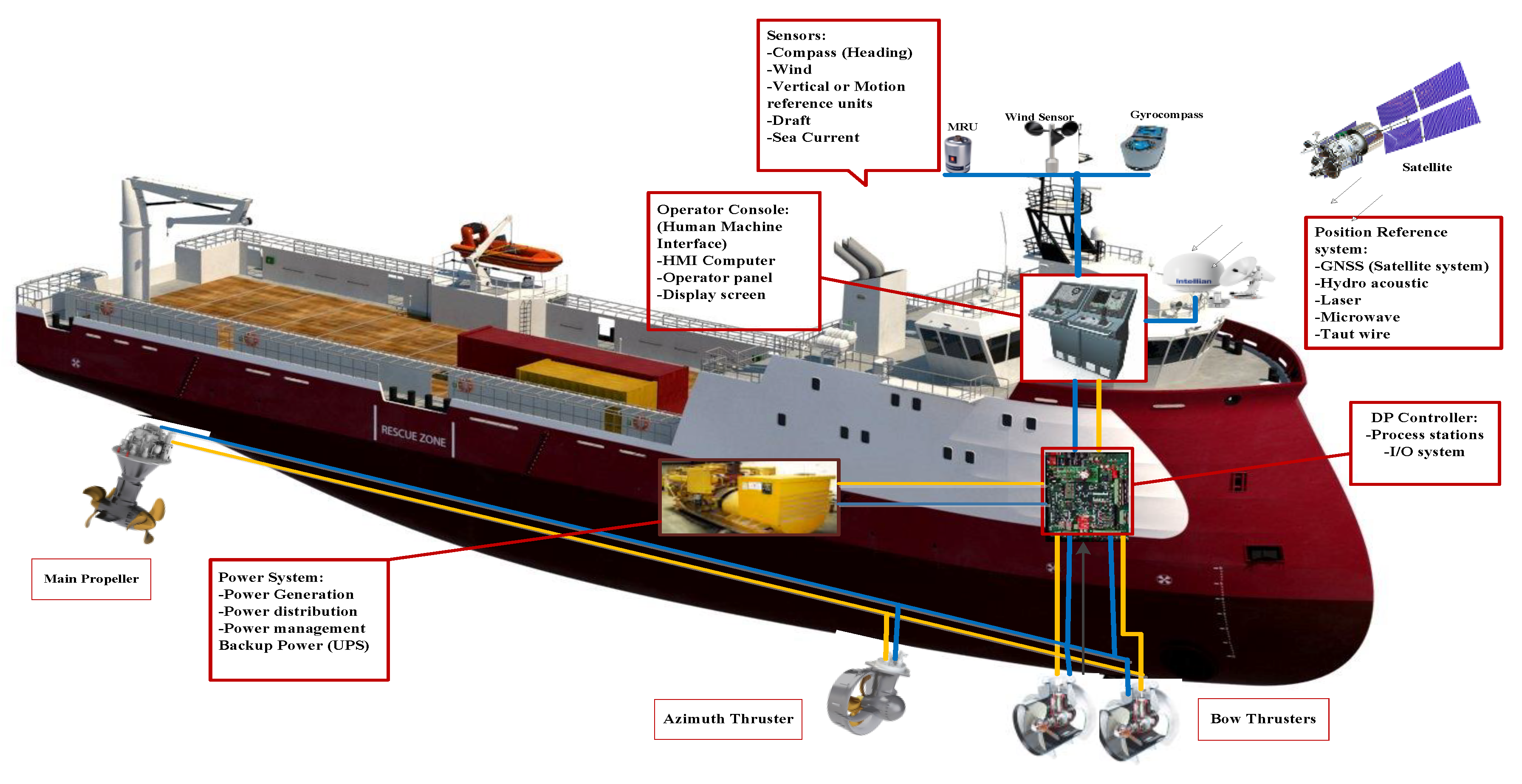
Figure 2 depicts a DPS consisting of sub-systems that are made known as follows:
2.1.1. Power Subsystem
The DP ship power subsystem consists of power plants, distribution and switchboards system, transformers, electronic power units such as adjustable frequency drive (AFD), motor control system (MCS), energy-storing devices (ESD) and observing and robotics system. They contain essential units for providing efficient power for the DPS performance in various sea states.
2.1.2. Signal Processing Subsystem
The signal processing subsystem includes all the data sent by movement and weather sensors, and satellite reference units. The measured signals pass systematically and analyze the signal processing in a module separately to provide data for the station of the vessel in the operational condition. Then, the DPS computes the essential thrusting force to compensate deviations of the ship movements in the setpoint place.
2.1.3. Sensors Subsystem
The sensors subsystem contains:
- CPU Processor/joystick systems console
- Instruments sensor units, etc.
- Station reference unit consists of:
- -
- Navigation system
- -
- Acoustic systems
- -
- Microwave and laser systems
- -
- The interface control unit, which is used as an interface to read the thrusters, switchboard feedback signals, as well as outputting command signals from the DP system to external units.
- Observing system and operator control panels.
2.1.4. Thruster Subsystem
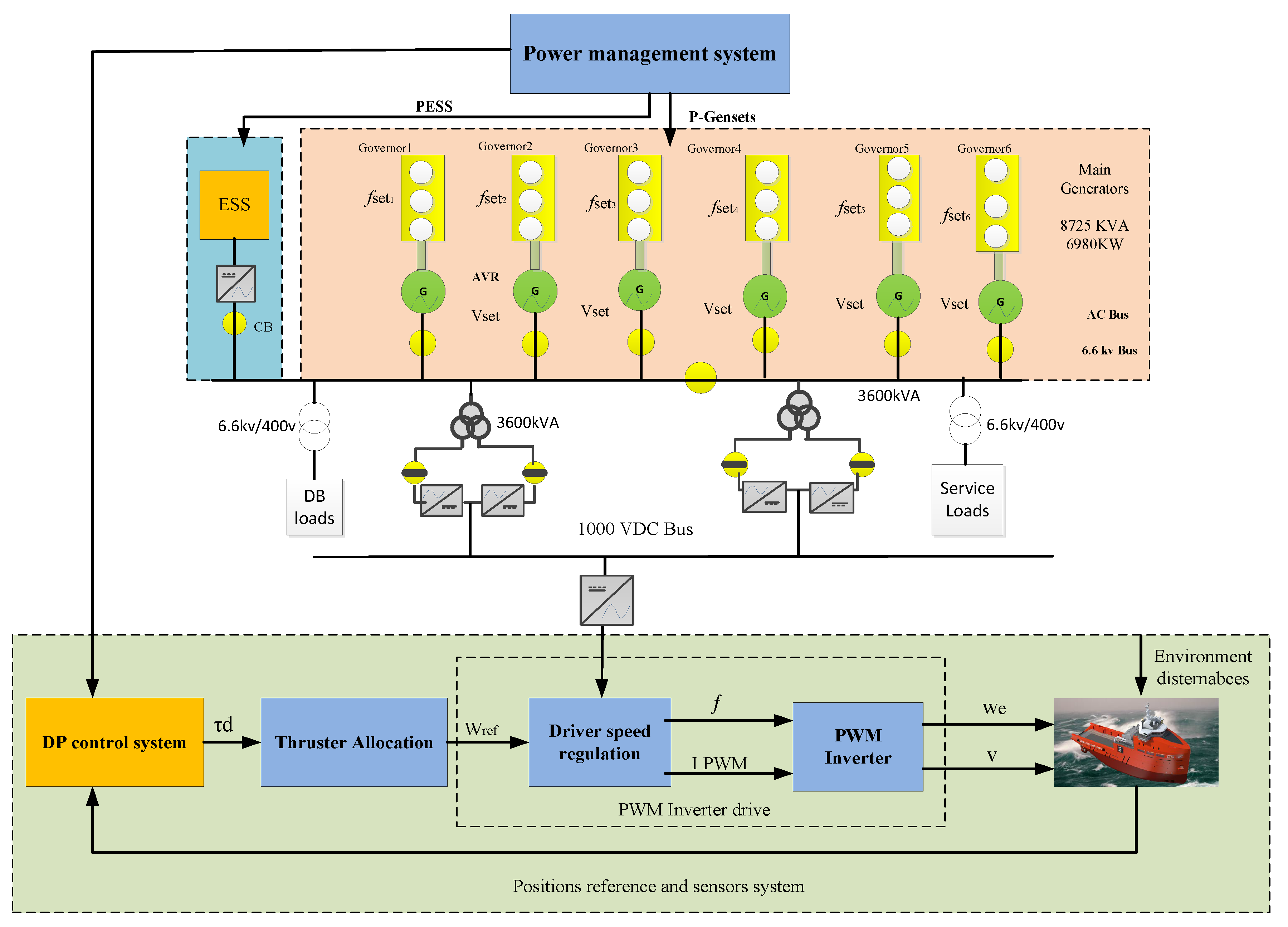
In the main DPS components, the thruster subsystem consists of important mechanisms, such as electronic drive units, principal propellers, bow, stern, and azimuth thrusters. They are controlled by DPS to compute allocating thrust force and tracking the path. The research in this area proposes that the high-level positioning controller can be applied to predict the required forces in the 6 degrees of movement. Moreover, the thrust distribution system (TDS) which estimates the corresponding thrust power to command the direction of each thrusting motors has proposed in [40,41,42]. Furthermore, the effect of minimum control level of thrusting in calm to rough sea environments is emphasized in [50] to prevent the corrosion of mechanical parts, avoid the shutdown, and harmonic distortion in power delivery, respectively. The control framework of TDS and the overall methodology of DPS, electronic units, and power are presented in Figure 3. Accordingly, the information of position and speed movement of vessels measures by the sensors as we mentioned in Section 2.1.3. Consequently, the measured data are transmitted to the DPS to compute the torque reference (τd) for low or high-level of thrusting in different sea states, such as calm to the extreme, respectively. Then, the power plant generates sufficient power and moment of force, where the vessel velocity reference is estimated by TDS to carry the ship to the desired position. The TDS set of rules efforts to synchronize the thrusters to match the computed torque τ with the reference. Hence, the TDS algorithm follows the reference strictly with slight deflections from the setpoint to enhance the performance of power plant conditions. For decreasing power consumption, TDS is essential to monitor the minimum power reference by resultant in transient deviation from the vessel position. On the other hand, PMS usually needs to confirm certain changes and inform the imminent fluctuations for the maximum existing power and the present power consumption to TDS caused by the massive deviations from the heavy load consumers such as winches, rotating equipment in drilling, and cable laying operation. Therefore, the TDS controller computes the command of thruster power to rotational per minute (RPM) order to drive speed regulation thrusters and feeds by generators. Furthermore, the level of thruster controller provides the prospect of predicting and restricting the deviances of signal errors in the vessel location since the local thruster controllers do not have any notice about the performance of the other regional controllers. Therefore, they are not able to calculate the variations in the resultant generalized power. Nevertheless, to counteract thrust load fluctuations, local thruster controllers have to be able to reduce and increase the power demand. Hence, PMS is used to adjust the available power signal in power plants for the thruster controllers.
2.1.5. Power Management Subsystem
The capability to execute and maneuvering of vessel positions relies on the sea state and the capacity of the diesel generator power. Without doubt, inefficient power may lead to decrease DP performance, failure of power, and position, which may lead to a blackout. The principal confusion for the power system of a DP ship is that the power of the thrusters in rough sea states may lead to a larger energy ratio than the power plant capacity. The extreme DP demand in power units and distribution in DP operational mode may potentially enhance the risk of a shutdown in all kind of DP vessels. Consequently, the redundancy of power systems due to increasing the reliability of the power system by using energy storage systems such as the battery, flywheel, ultra-capacitors, fuel cell, etc., is costly as shown in Figure 3. Furthermore, cost-effective and energy efficiency solutions for investing in tools, conservation, harmful gas emission, and fuel consumption because of generators running hours are significantly demanded. For instance, the doubts in electrical power demand of drilling, shuttle tankers, cable, and pipe laying where the importance of DPS for transferring energy from offshore wind farm by cable laying, oil resources by tankers in operational condition are made disturbances for the PMS to provide thrusting power [36,37,38,39,40,41]. In addition, the PMS be able to control the optimum power flow be sure of DP demand in the future operational condition. In this way, the DP load profile can be predicted by PMS based on effective optimization algorithms [42,43,44,45,46]. As a result, the flexibility of power balance amongst power plant and the DP command demand for producing sufficient energy resources by using advanced control techniques for PMS is very crucial in the marine microgrids [47,48].
2.2. Dynamic Positioning Vessel Classification
On the authority of the international maritime organization (IMO) and global maritime standards such as American Bureau of Shipping( ABS), Det Norske Veritas (DNV), Lloyds Register (LR), and so on, DP ships are referred to classes (1–3) which are briefly described as follows [51,52,53,54]:
- DP class 1 is not redundant and can be positioned for a particular fault.
- DP class 2 is redundant to facilitate no particular fault in the operational condition lead to system failure. Therefore, loss of vessel position does not occur due to a particular fault on the power generations, distributions, and automatic valves, etc. However, it possibly failure will happen for example in cables, pipes, manual valves as a static system.
- In vessels with DP class 3, flooding or firing occurs must also be removed in a non-system enclosure. A loss of position should not result in a sudden defeat, including the entire distillation section of the fire or the dewatering chamber.
Table 1 shows a summary of the IMO based on DP classification corresponds to DP system components.
2.3. Dynamic Positioning Mathematical Model
The mathematical calculation of DP vessels has a complexity class function. The first class is described as the hydrodynamics typical procedure plant of vessels, which is a simplified mathematical explanation and low-reliability model. This model would be set up as a part of the controller and is signified as kinematic development that encloses the vital physical properties process individually. The second mathematical model may have a general introduction of the actual construction, which is expressed by high-reliability model formulations [55]. The key function of this simulation model is to the dynamics of an actual vessel during the procedure of environmental disturbances, sensor outputs, and control inputs. Moreover, the control models of roll and pitch are introduced in [56] for damping the vessel motion of roll and pitch in small-water plane areas. However, the execution of control gains for roll and pitch may be required to design an observer for approximating the roll and pitch angular velocities. For this purpose, a mathematics reference model in DP vessels is used; this produces a flexible set point to estimate acceleration, speed and position reference that are inputs to the positioning controller. In [57], the authors described more details on reference models, guidance systems, and some models of the local optimization reference points. Table A1 in Appendix A illustrates a summary of DP mathematical models.
2.4. Dynamic Positioning Control Principles
Due to a lack of land resources, exploration in the oceans has been enhanced in recent years. The ocean is doing a significant role in the development of economics and society. Therefore, the exploration of ocean hydrocarbon resources has increased the demand for the DPS concept. DP systems assist the vessels to be defined in a specific location or predetermined direction of platforms against ocean environmental disturbances such as the wind, waves, and currents by using their propulsion systems and engines. Compared to conventional stationary keeping equipment and anchor handling operation, the DP mode has many advantages, containing positioning accuracy, a high degree of flexibility, ability to operate at any depth of water, and avoiding marine pollution. Correspondingly, DP systems have been widely used in different marine operations such as oil and gas exploration, cable, and pipe laying. The first DP system, based on a conventional controller adapted to the PID, was introduced in the 1960s [2].
The main achievements of PID based location development show that the PID controller can be used to control the horizontal motions of vessels by using the thruster control system. This control method was established in the 1970s, and the creation was named as DPS. The PID controller design for DPS is considered an automatic feedback control problem that is a challenging problem to prevent the forces of the first wave in the feedback loop. Some methods, such as the notch and low-pass filtering, were tested for this purpose [6]. A ship is exposed to sea disturbances, forces and moments produced by the ship’s thrusting system. Position reference systems, gyroscopic compasses, motion reference unit, or vertical reference sensors measure the responses of the vessel to these deviations in position, heading, and speed. Reading reference systems for scroll and ground are modified by reading from vertical reference sensors and measured by wind sensors. The DPS is dependent on the mathematical computational of the vessel, which comprises hydrodynamic properties such as current tensile coefficients and robust mass data [5].
3. Review of Dynamic Positioning Controls
The DP controller includes a feed-forward and closed-loop controller. The closed control loop suggested by Balchen has been encouraged and modified to the DPS concept. The calculation of the feedback signals used in the controller as described in [4,5,7,55,56,57,58,59] based on Kalman’s theory and survey. Complementary, further progressive control methods constructed on multi-adjustable control optimization and Kalman’s filter concept are developed in the DPS control techniques as follows in the following subsection:
3.1. Expanded Kalman Filter (EKF)
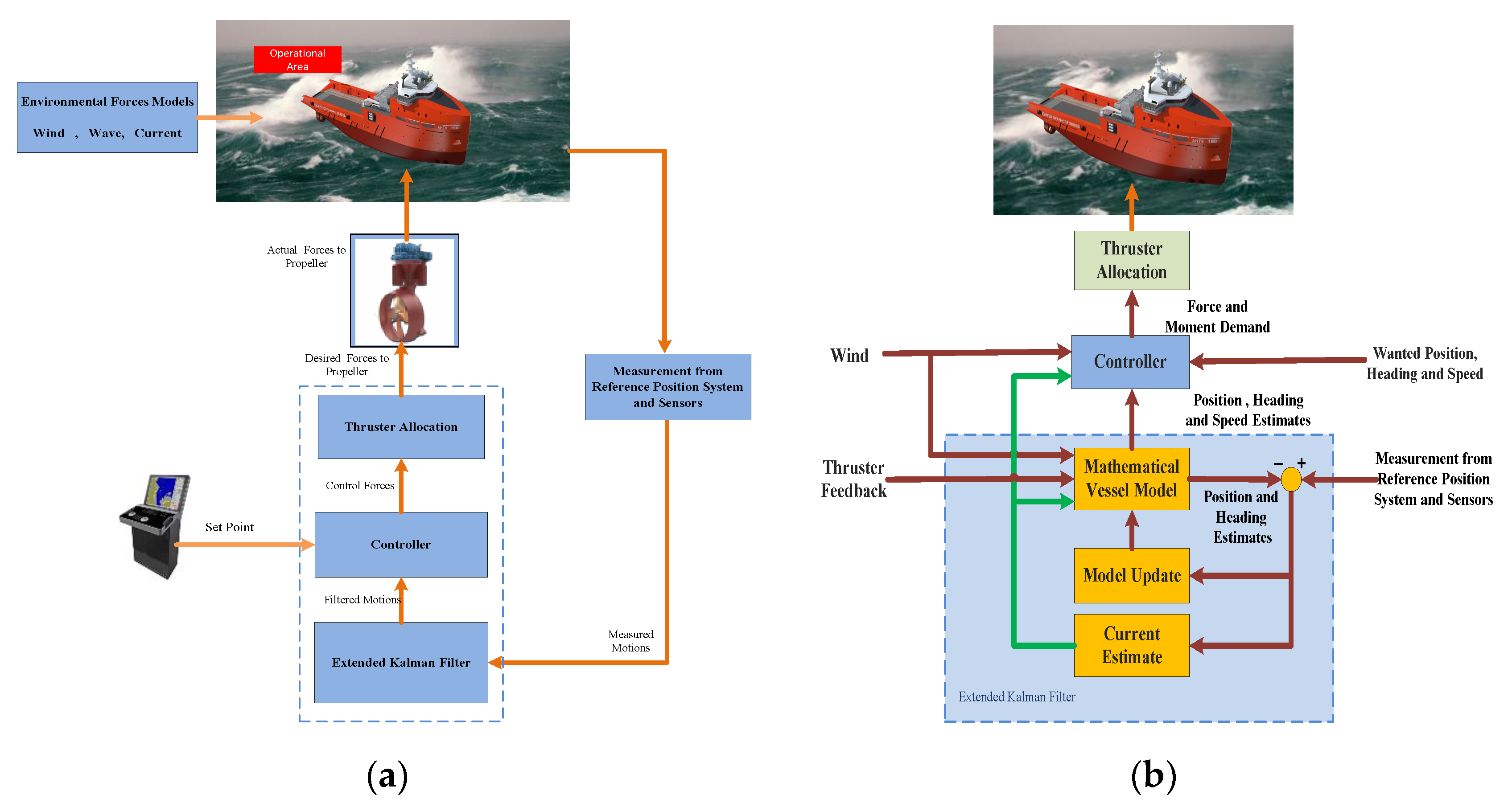
The (EKF) is introduced [55] to approximate the heading, position, and speed of the ship in each of the three degrees of independence such as surging, swaying, and head deviations. It also includes algorithms for computing the influences of the sea currents and waves. The EKF uses a mathematical pattern of the ship to the precise demo of the real vessel motion behavior and constantly corrects the model. The ship head and position deviations are evaluated by using of gyrocompasses and position reference systems as input data to the DP system [56]. These estimates are compared with the predicted measurement data generated by the mathematical model and the variances are then used to update the model.
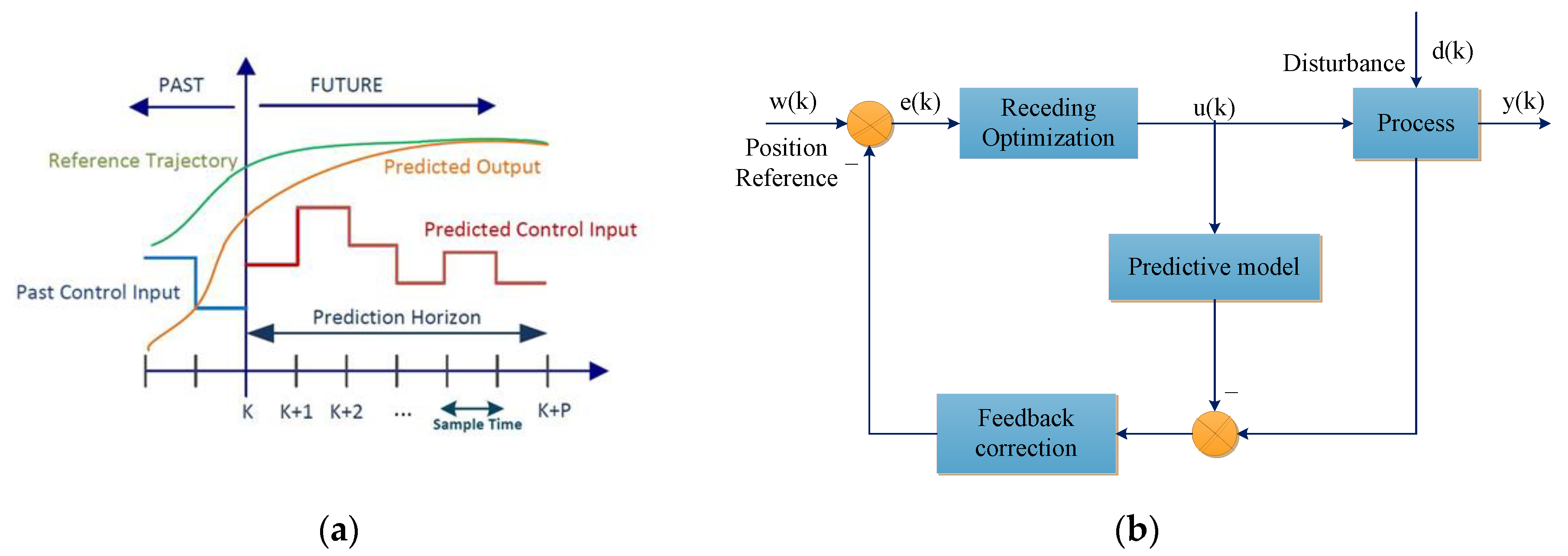
The position reference system computes a deviation for each position reference system in use and places various weightings on their estimates according to each system’s individual quality in the absence of position measurements [57]. That is to say that the system can perform positioning for some time without position measurement updates from any position reference systems. In the EKF, the mathematical ship model reliability and the noise level of the position measurement are the basis for deciding how much to trust each estimate [58]. As time passes, the model uncertainty will be reduced by learning from estimated ship responses. The method is tuned if, for instance, only one position reference system is active, and it has a little update speed. In this situation, the model uncertainty may be increased in the period between measurements, and the ship model will be comprehensively updated with each analysis [59]. Figure 4a,b demonstrates a simplified block scheme of the DPS controller and the expanded Kalman filter.
3.2. Model Predictive Control Model
Over the last three decades, the concept of predictive model control has been widely used in the industrial control system developments. In 1978, Richalet introduced his popular papers on the event, application, and implementation of the MPC algorithm. The theory of MPC utilizes a quadratic operational withdrawal optimization objectives and control response adjustment strategies to dominate the effect of signal error, controller parameters, and the environment through the other undefined issues based on the predictive model [60,61].
As a result of the computer software and hardware technological development, it has become possible to integrate the DPS and thruster controller into a combined algorithm through MPC. Accordingly, The MPC can mathematically perform highly accurate control of unknown plants by using linear models of ship dynamic in the area of the desired position. Moreover, the advanced method based on feedback linearization is evaluated to reduce the mathematical model nonlinearity. The MPC control technique simulates the future behaviors of ship replacement by using previous control input results and, consequently, predicts suitable control output responses. It allows constraints executed on both input and output variables to predict disturbances’ impact on future procedure evolution. Hence, the prediction model includes capabilities in the optimization method to predict the dynamic response of vessels over a specified time horizon.
The MPC algorithm method is used for different restrictions of advanced control methodology with complex controlled targets. In recent years, MPC has become an essential tool in the control fields of industry. Due to the nonlinear behavior of DPS, the MPC was suggested for DPS as an advantageous algorithm to overcome the conventional control method [30,31]. Based on an iterative characteristic, the MPC algorithm is bounded perspective optimization of the dynamic model of a plant, and it likewise is termed by a receding perspective predictive controller (RPPC). The RPPC is defined by improving a particular performance index, there usually is an error between the expected output from the plant type, and the anticipated output over a time prospect is calculated to achieve the optimal input of the proposed controller. The optimum control methods are used to measure the production of the system at a time interval, which should be modified. The previous steps are recurrent so that the error in detection prediction is reduced to a limited range.
Figure 5a demonstrates the control concept of the MPC in the time prediction horizon. The general characteristic of the main block diagram of MPC is shown in Figure 5b. In DPS applications, the mathematical model of the process involves external changes in wind, current, and wave disturbances and limitations in the input and output variables. Therefore, the design of the DP controller is very complicated due to nonlinear models, uncertainties, disturbances, multivariable input and output, and restrictions. There are currently some articles related to this problem that suggest different nonlinear control methods [32]. The most appropriate manner in this approach is the design of the MPC control method. The MPC provides high- efficiency controls in cases where the precise mathematical model of the control system is not fully understood. Furthermore, these systems allow for the limitations of both input and output variables to predict the effects of disturbances on the evolution of the future trend.
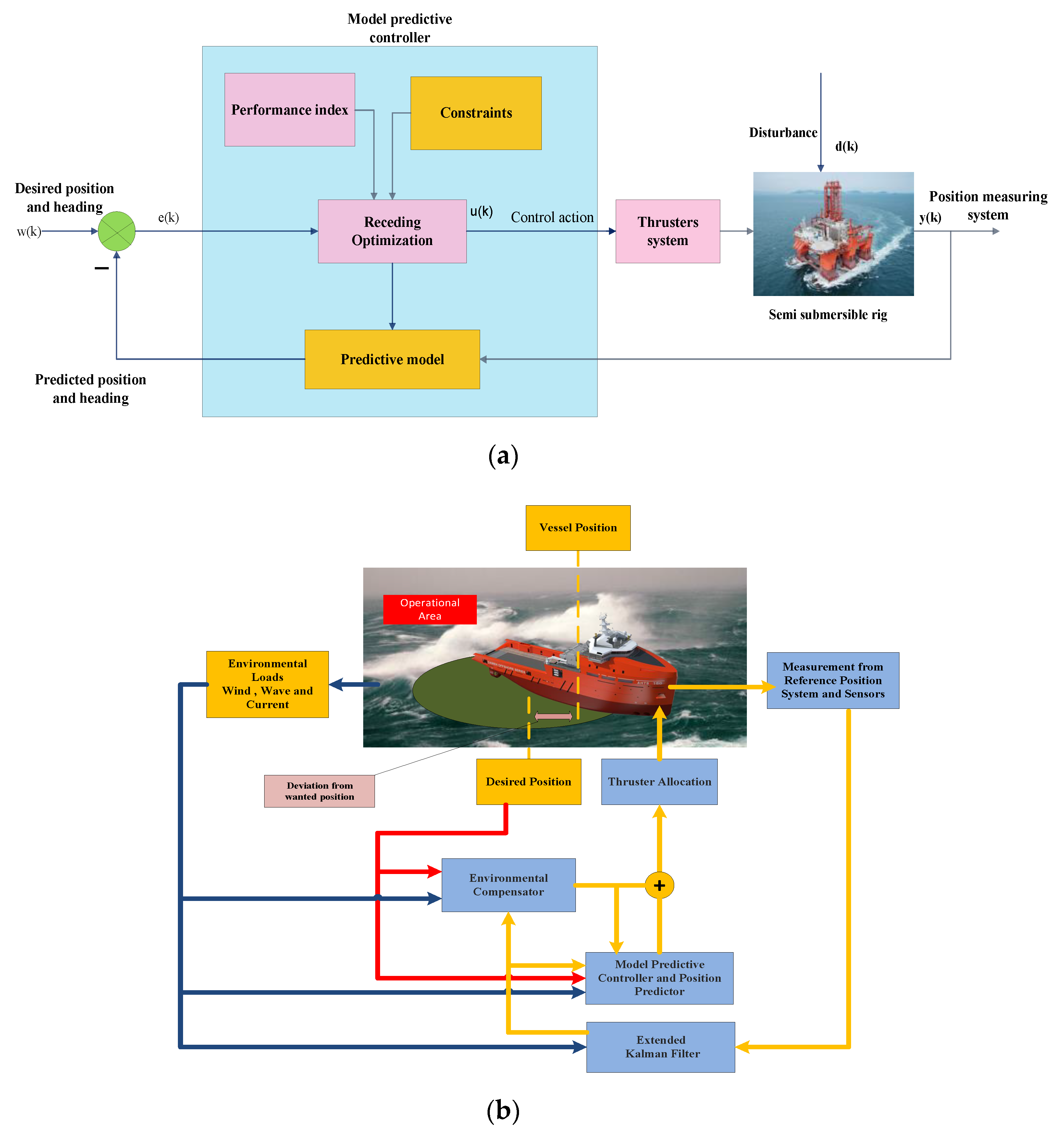
Figure 6a shows the main blocks of the MPC controller used in semi-submersible rings. For instance, in [33], it was shown that the MPC can be successfully executed for DPS that is the subject of high-quality control changes in unparalleled limitations. Currently, the MPC control can be executed in real-time using modern computers in many conditions. Therefore, we need to increase the scope of implementation of MPC operations for DP vessel control problems. By using the deviation between the operator-identified position/heading set points and the moment set point, the variances are multiplied by gain elements giving a force set point which includes restoring and adjustment setpoints [34]. These setpoints are essential to return the ship to its setpoint values. Figure 6b illustrates a simplified MPC based DP vessels controller where each block gives its contribution to the control shown as follows:
- For measuring the average of environmental forces induced by the sea disturbances, the environment compensator is used to maintain the necessary position under averaged conditions.
- Predicting the current position of the ship movement as input for the MPC control. While the operational restrictions are predicted to be overcome, the controller responds to guarantee that the ship stays within the functional area. For the nonlinear predictor controller, a model is an online optimization feature that finds the best possible mix between the use of thruster and the prediction of passing through operational constraints. The position predictor includes the ship motion mathematical model used in the DP Kalman filter.
Furthermore, two robust DPS approaches are proposed in [35] for autonomous surface vessels when full states were measurable and only partial states were available with measurement errors. The proposed linear models in the local area of DP setpoint estimated high commitment nonlinear hydrodynamics. The linearization errors were seen by the authors as bounded unmolded dynamics and were accommodated in the MPC together with environmental disturbances. In this prediction method, the MPC based on the tube controller consists of all the possible uncertain trajectories in a tube that was based on a precomputed robust positive invariant set and a nominal trajectory solved online. Both controllers included a feedforward part by compensating the predicted environmental forces, a nominal part guiding the vessel towards and stabilizing it at the principle, feedback part bounding the undefined vessel trajectory contained by the tube. Additionally, an output feedback robust DP controller was recommended by applying a simple Luenberger observer to approximate the system statuses when full states were not obtainable. The resultant approximation and measurement errors were also integrated into the MPC based on the tube. The results are shown that the proposed control techniques for DPS can succeed for the DP objectives within system constraints.
3.3. Fuzzy Logic Control Method
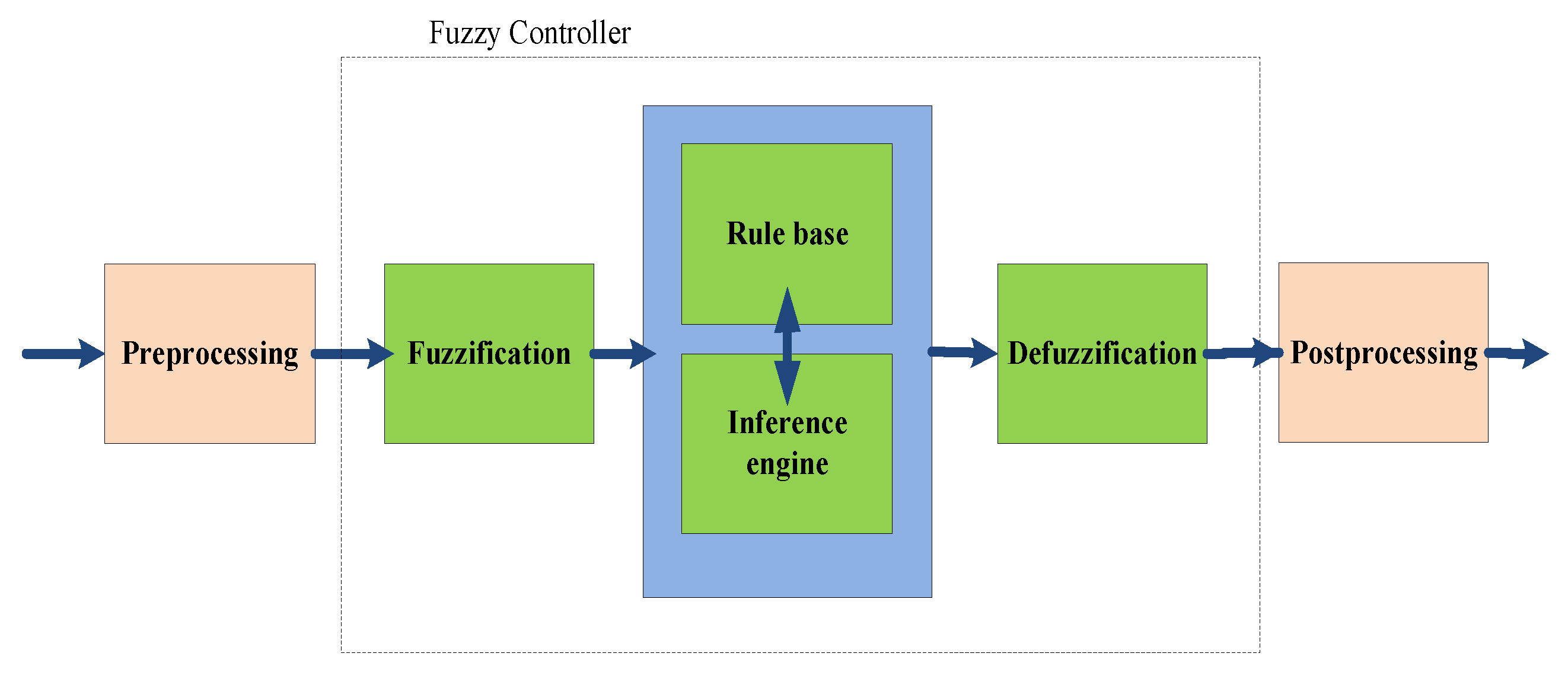
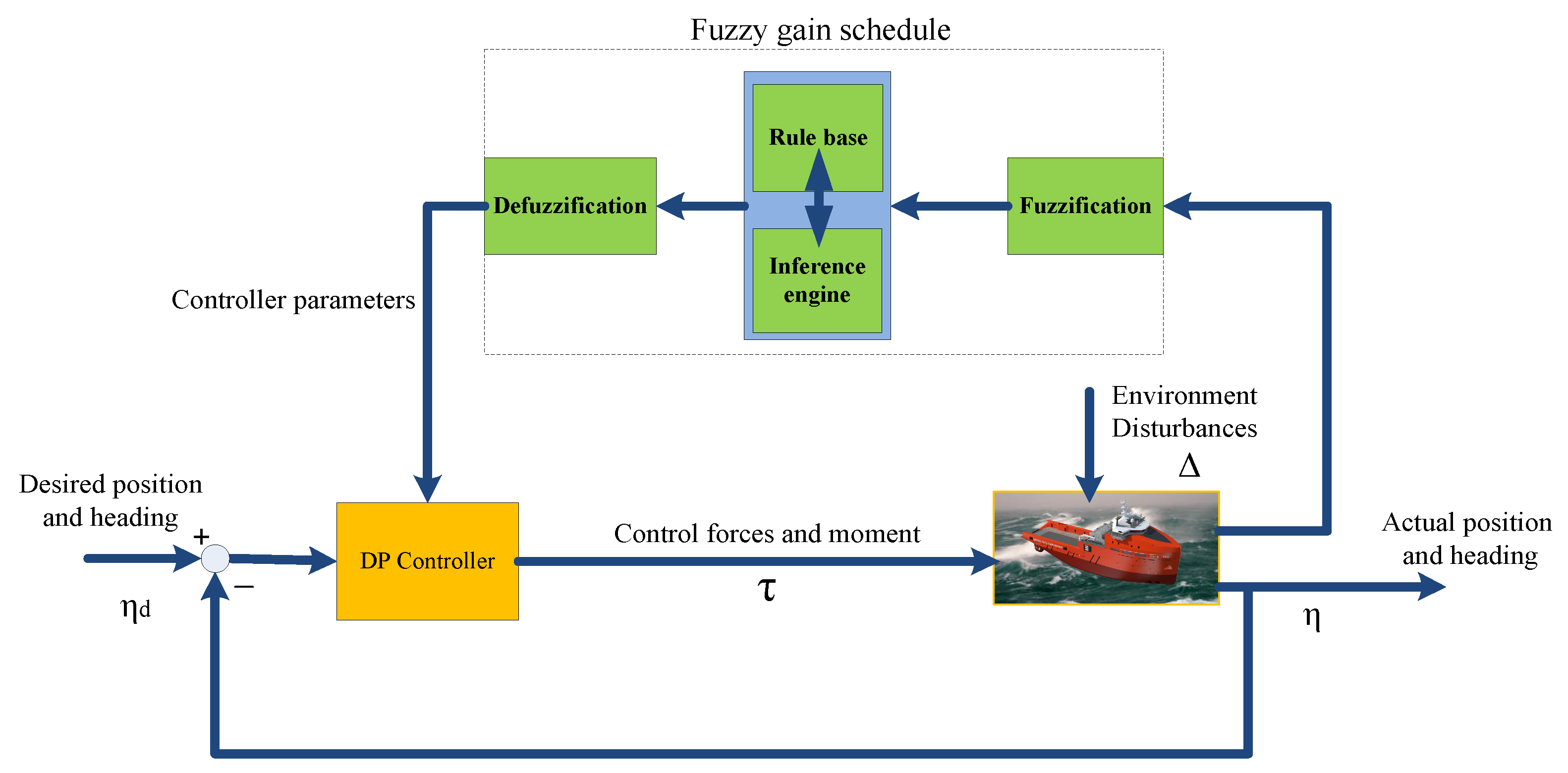
The fuzzy logic control (FLC) method has been mentioned as one of the most attractive zones for exploration into applications of FLC theory. The Zadeh introduced the revolutionary investigation of Mamdani and his colleagues based on the philological method and system analysis that is named the theory of FLC [62,63,64,65,66]. In the FLC, the logic is fuzzy control and very close to the mind of human thought and the natural language of traditional logical systems. Essentially, it is a useful tool for grasping the true and false nature of the real world. In this view, the FLC is a set of language control rules related to two fuzzy concepts and hybrid rules of a system inference. Fundamentally, the FLC provides an algorithm capable of transforming a language control strategy into an automated knowledge-based control strategy. The FLC produces superior results to conventional control algorithms. The FLC method is particularly useful when complex processes are used to analyze techniques commonly or when available sources of information are qualitative and passive or uncertain. The main block of the FLC is a set of language rules, which is termed as the rules base. The rules are known in the ‘if-then’ format that the conditional format is ‘if,’ and the part ‘then’ is named the conclusion. The input value of ‘Ng’ is a language word that is short for the word “negative”; the output value ‘NB’ stands for the negative big and ‘NM’ means as a negative medium. The computer can perform the rules and calculate the control signal relating to the measured input error and deviation of the error. The particular modules of the FLC such as preprocessing, fuzzifier and rule interface, a rules base, defuzzifier, and post-processing to support a design method. Figure 7 shows blocks of a fuzzy controller between two processing blocks. The structure of each block is explained as follows:
3.3.1. Preprocessing
In the preprocessing step, the inputs are normalized or scaled to an exclusive and standard range and filtered to eliminate the noise before they enter the controller. The data are most often complicated from some measuring rather than linguistic equipment A preprocessor, as shown in the first block in Figure 7, represents the measured parameters before they enter the controller. The benefits of preprocessing DP fuzzy controller are:
- Adjusting the gradation error function as integers.
- Normalizing or scrambling to a specific standard collection.
- Clarifying due to the Removal of the noise of environmental sensors.
- Combining several measurements to achieve main indicators, variation, and integration.
3.3.2. Fuzzification and Defuzzification
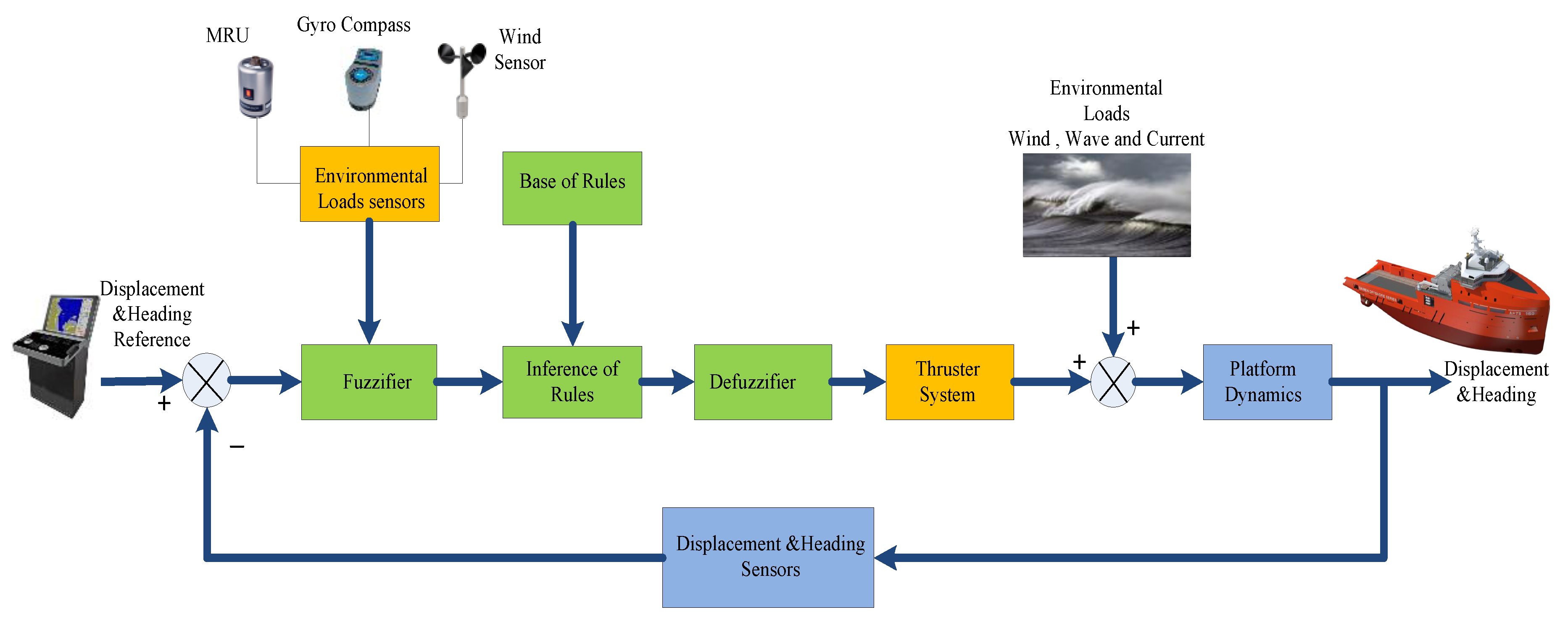
The fuzzification method has been executed as a significant role in processing uncertain information, which might be independent or biased in natural language. The measurement sensors transfer the data into the fuzzier block, as shown in Figure 8, and fuzzification processors theoretically convert the dubious value into a fuzzy degree of membership in each of its fuzzy linguistic sets. In designing the membership functions, the following guidelines are used. When developing membership functions, the following instructions are used. The fuzzy block includes two inputs, errors, and error rates that are obtained applying five fuzzy subsets; each allocated rule with the language label is between the language community (−1.1).
There are some membership functions allocated to fuzzy subsets rules such as NS (negative small), ZZ (zero), and SP (small positive), even though the Trappist membership functions are subdivided into fuzzy subgroups: NM (negative medium) and PM (positive medium). The works in [67,68,69,70,71,72,73,74,75,76,77,78,79] presented the fuzzification membership function for fuzzy controlling in DP vessels. The output membership degrees and linguistic rules cannot be used straightly. Therefore, the fuzzy controller output block is essential converted to a numerical value that can be recognized as sent to control signal processors by using various defuzzification methods.
• Rule Base
FLC is considered by a set of language declarations based on skilled information. The skilled information is generally used in the form of “if-then” rules, which are simply executed by fuzzy provisional declarations in FLC. The set of FLC rules that are shown as fuzzy rules or the rule set of an FLC. For instance,—IF error (e) is “Medium Negative (MN)” & IF error difference (∆e) is “Medium Negative (MN)” THEN force output (t) is “Large Negative (LN)”.
For instance, authors in [67] evaluated a fuzzy rule-based PID controller to estimate outputs of DPS position error and low-frequency speed to overcome environmental disturbances. The efficiency of the FLC is estimated mathematically over a time sphere for a DP semi-submersible rig.
• Post Processing
For instance, an FLC is proposed in [75] for the DP of drilling vessels such as drillship and semi-submersible in deep water. The works presented in [70,76,77] focused on the fuzzy controller design, which is very simple and needs no mathematical modeling of a complex nonlinear system. These studies used the fuzzy controller to consider the vessel heading, yaw speed, distance, and speed of the position, including location and heading to produce control outputs to maintain and keep the vessels in the desired position. Figure 7 indicates the blocks of a DP based FLC. The result of simulation displays that the FLC can have an acceptable presentation rather than a conventional automatic DP controller.
Generally, the DP control system has time lag results in delayed defects due to its mechanical properties and sudden environmental changes. Hence, drives are the most critical elements of DP vessels and can have time lag impact and, therefore, it is essential to resolve the time delay problematic. Because of sea instabilities, the response of FLC can be postponed, and it cannot be compensated promptly, which may result in reduced or even oscillation dynamic systems. The outcomes show that proper control methods based on fuzzy logic control can be designed to solve the time delay of passive controls [73].
3.4. Fuzzy Adaptive Control (FAC)
FAC control rules are applied to modify the adjustment parameters in controlling the matching metric, if the nonlinear scheduling variables that adjust the set point of parameters; some references for considering this architecture can be found in [15,16,17,19,20]. In these references, studies are considered the FAC design for the DPS by combining the backstepping control methods. The result shows that the proposed method control system can keep the ship with arbitrary values of the desired position and heading to ensure maximum accuracy of uniformity of all the DP control system signals in the closed circuit. Taking one FAC as an approximation of the control method is no need for any prior information of the ship-dynamics typical and sea disturbances.
Furthermore, the research in [20] considered the unidentified time-fluctuating dynamic model factors and the interfering of sea conditions estimates the doubts to increase controller performance efficiency. The paper is evaluated comprising of the FAC based on sliding technique, with the sliding mode control and an adaptive fuzzy logic controller. The proposed technique for the DPS is that to keep the vessel at the anticipated station and header in environmental disturbances. The DPS law is aimed at the sliding control technique for a drillship with sea disturbances [17]. The FAC-based sliding technique is proposed to evaluate the doubts induced by sea instabilities as parameters of the unidentified time-fluctuating of the dynamic scheme. Figure 9 shows the blocks of a DP fuzzy adaptive controller.
3.5. Neural Network Control Method
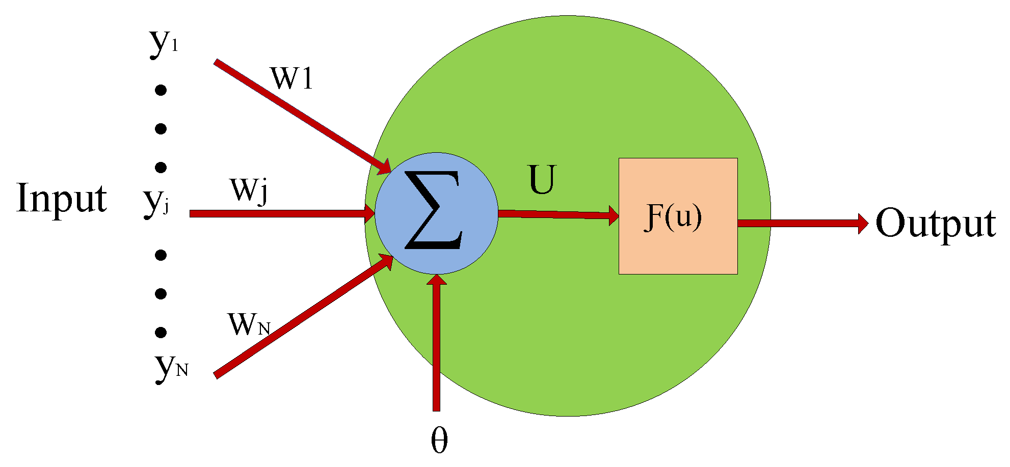
The concept of artificial neural networks has been developing considerably. Due to the nonlinearity essence of neural network (NN), the capabilities of NN to learn unknown system behavior from their atmospheres and the global estimate property of neural networks in controlled methods make that appropriate for solving problematic signal processing. The challenge of measuring the area of neural networking models is to classify those neural network configurations that have been expertly designed to solve actual-world problems [80]. It is essential to recognize the nature of the DP problem. Many studies were suggested that intelligent controls can be used to enhance the control performance and operating safety of dynamically positioned marine vessels [81]. Therefore, the neural network seems to be a suitable solution for solving the DP problem. Furthermore, it is also significant to evaluate the effect of neural networks on efficiency and reliability. Another main subject is assessing the NN models, learning a set of rules, and features estimation and determine those for solving signal processing problems [82,83]. For instance, various neural network models have been developed, and all contributions have a common building block. As shown in Figure 10, it is identified as neurons and their network as an interconnected feature. The proposed method illustrations how a NN can learn itself to control a DP vessel. The NN consists of inputs and outputs system, connected via many neurons for processing self-learning algorithm features. Each neuron has several interior factors entitled weights. Varying weights of neurons changes the behavior of the system, and by extension of neuron layers, the behavior of the entire network will also change. The main target to change the weights of the NN is to accomplish an anticipated network output. The procedure is recognized for the preparation of the NN. In Figure 10, the activate function F(u) which can be a linear or nonlinear function is expressed in (1) to illustrate diagram including the sum of inputs multiplied as a result of the weights and the bias, then passed through an activate function. Table A2 in the Appendix A shows the summary of the NN function methods as an input of function F(u), where different NN models with various activation functions are proposed in [84,85]. Moreover, the most frequently activation functions and their derivatives, are summarized as the final output in Table A3 in the Appendix A.
where N is defined as inputs, j is related inputs number, is assumed as the weights of the input j, yj is the input j and is the bias.
3.6. Neuro-Fuzzy Control Method
The DPS based NN consists of controller coefficients as the proportion ratio (KP) and derivation rate (KD) in the PD controller. However, the controller coefficients of the integral (KI) do not consider in the PD controller, and the steady-state error existed. In [86], it proposed two series-parallel models; neural networks 1 and 2 (NN1) and (NN2) with one hidden layer and 15 nodes. Both of NN1 and NN2 identified and estimated the nonlinear dynamic correlation concerning the ship position deviation and the speed of thruster spinning. To achieve the optimum PD controller coefficients for the DPS, the NN1 and NN2 are applied for the self-tuning parameter by the sigmoid activation function method as shown in Table A3 in Appendix A.
Conversely, in a fuzzy DP control system, the database rule and membership function parameters were required to adjust manually, where the process of tuning the parameters was complicated and time-consuming. Therefore, the neuro-fuzzy controller has been introduced to achieve the optimal parameters to train NN based on fuzzy logic rules. Particularly, the benefits of this DP technique are to control the vessel about maintaining position and heading accuracy. In the DPS based on the adaptive-NN-based on a fuzzy inference system (ANFIS), most of the controller coefficient can be achieved by self-tuning the parameters by applying back-propagation learning algorithm (BPLA) and rule-based functions on their extensive knowledge and performance [87,88,89]. The fuzzy neural network DP also indicates the advantages of minimum positioning deviation and thrust force requirement. Furthermore, a DPS based on fuzzy-NN can succeed with significant control performance under most uncertainties conditions.
A multilayer perceptron in NN relay on recurrent sliding mode is applied to actuate the dynamic surface structure (DSS) and controlling the surface of the vessel with undefined dynamics model in external disturbances, where the input of controller is necessary to be restrained. The BPLA for MLP in NN is aimed to improve the robustness in contrast to the uncertainties scheme. Accordingly, an adaptive law is proposed to recompense the NN estimation error and external instabilities. The recurrent sliding control method is integrated with the DSS to reduce the recurring derivative of essential control laws to increase the robustness of system accuracy. To decrease the possibility of actuator impregnation, the author is proposed a flat hyperbolic tangent active functions integrated with the controller scheme in [90]. Meanwhile, the Nussbaum activation function is utilized to recompense the impregnation occupation and make sure the controller stability in sea disturbances. Moreover, they are shown that further down the suggested control technique, even though the existence of system doubts and instabilities, the signal error will be able to meet into randomly minor areas about zero, whereas the restriction necessities on the control strength and torque are not interrupted. The proposed control method is proven by using the Lyapunov function, which could be assured of the identical constrainedness of all signals in the closed control loop. Hence, an adaptive robust NN controller-based BPLA is designed to control the dynamic surface of DP vessels by integrating of the sliding control method. To control vessel position tracking under the actuated independent of the vessel surface, which is exposed to parameter uncertainties and environmental disturbances. Additionally, a Lyapunov synthesis is applied to verify the permanency of the closed control loop. Therefore, the Following novelties are highlighted in [90]:
- To overcome the computational difficulties of the conservative BPAL method, the derivatives of the virtual control signals are found through the dynamic surface control.
- The proposed designed controller could be easily employed in practical applications with no requirement to apply the neural network and state approximations to collect model parameters.
- The prediction errors were combined with position signal errors to organize the neural network updating laws, which improves the neuron weight adjustment and tracking performance.
On the other hand, deep-sea mining (DSM) is an innovative intelligent control methodology to analyze DP vessels dynamically and active heave compensation constructed on radiating basis function (RBF) based NN. Furthermore, the RBF network algorithm is used in the MLP-NN instead of feed-forward-NN based on BPLA on DPS to decrease the signal errors on the platform supply vessel (PSV), wave frequency (WF) movements which they have an important impact on the controller responses in the dynamic of subsea operations [91].
3.7. Adaptive Sliding Mode
Adaptive Sliding Mode is an advanced technology for DP ship by making an allowance for the unidentified time-fluctuating in sea disturbances, and momentary performance. A continued limited-time status supervisor approximates the unscaled status of DP ship in the determinate time and a supplementary controller to perform the control satiation. Furthermore, the designed method is a station descending type exterior with the signal produced by the supplementary controller while the decent momentary performance is accomplished lower than various restrictions. Hence, the insignificant controller output feedback is guaranteed a steady-state performance. Moreover, an adaptive updated law in the previous information of disruption is not required, and the limited-time conjunction of the control loop is verified strictly. By designing the limited-time control theory, the method is guaranteed a quick conjunction ratio of the controller closed loop for analyzing scheme stability. The comparison of results is shown that the benefits and enhancements of the proposed control method for DPS, which includes a minimum calculational difficulty procedure to regulate the DP controller frameworks with position constraints and dynamic uncertainties [92,93,94].
4. Conclusions and Future Research
A review of DP controller developments for marine vessels has been presented. The comparison of the intelligent and conventional controllers proposed in the literature is presented in Table A4. It has been shown how the initial innovations appear from PID, Fuzzy, MPC and NN, and adaptive sliding mode controllers. Particularly for improving the accuracy of DP control to keep the position in environmental conditions, many studies suggested that intelligent control methods can be used to enhance the control performance and operating safety of dynamically positioned marine vessels. Whereas the DPS performing and maneuvering depend on the thruster control system, generators capacity, and power-sharing reliability, that are crucial in dynamic positioning vessels. The review envisions that the application of different control techniques for power and energy management in dynamically positioned marine vessels is an important subject for future research and studies.
Author Contributions
Conceptualization, M.M. and C.-L.S.; methodology, M.M., C.-L.S. and Y.T.; validation, M.M., C.-L.S. and Y.T.; formal analysis, M.M.; investigation, M.M. and Y.T.; resources, M.M. and M.B.O.; data curation, M.M.; writing—original draft preparation, M.M.; writing—review and editing, M.M. and C.-L.S.; visualization, J.C.V.; supervision, J.M.G.; project administration, J.M.G.; funding acquisition, J.M.G. and C.-L.S. All authors have read and agreed to the published version of the manuscript.
Funding
This work was supported by VILLUM FONDEN under the VILLUM Investigator Grant (no. 25920): Center for Research on Microgrids (CROM). The work of Chun-Lien Su was funded by the Ministry of Science and Technology of Taiwan under Grant MOST 107-2221-E-992-073-MY3.
Conflicts of Interest
The authors declare no conflict of interest.
Appendix A

Table A1.
Summary of DP mathematical models.
| Mathematical Models | Formula | Description |
|---|---|---|
| Three degrees of freedom (3DOF), Low frequency (LF) of vessel movements [22,23] | ship velocity vector position and orientation where M is the inertial system matrix with the assumption that my plane includes mass distribution. The linear damping matrix is introduced with matrix D for LF application. The relation between and is given by 3DOF with principle rotation matrix about the z-axis, where is the swaying angle. | |
| Environmental Disturbances | The transfer function is used for simulating the wave forces and moments and passing band limit in a surface vessel in 3DOF. -This Model was introduced by Saelid [6], where he proposed the term as a damping term to develop the performance of the Pierson-Moskowitz spectrum. Beside KI is again for i = 1, 2, 3, expressive X, Y, and N. -Three different coefficients are used For generating forces () and moment () |
Table A2.
Summary of neural network functions.
| Network Functions | Formula | Comments |
|---|---|---|
| Linear | frequently is used for NN activation function | |
| Higher-order exhibited | x is a weighted as linear terms of the input variable. | |
| Delta | Seldom used |
Table A3.
Summary of neural network activation functions.
| Activation Functions | Formula a = f(x) | Derivatives | Comments |
|---|---|---|---|
| Sigmoid | Frequently uses and derivative of x as f(x) can be computed directly. | ||
| Hyperbolic tangent | T = temperature parameter | ||
| Inverse tangent | Less frequently used | ||
| Linear | a | Most commonly used |
Table A4.
Comparisons of DP control methods.
| Control Models | Advantages | Disadvantages |
|---|---|---|
| Model predictive control include Extended Kalman filters [30,31,32,33,34,35] |
|
|
| Neuro-PD controller [21] |
|
|
| Adaptive neural networks controller [22,89,90] |
|
|
| Neuro-Fuzzy controller [21,23] |
|
|
| Fuzzy controller [62,63,64,65,66,67,68,69,70,71,72,73,74,75,76,77,78,79] |
|
|
| Adaptive fuzzy controller (AFC) [15,16,17,18,19,20] |
|
|
| PID controller [2,24,25,26,27,28,29] |
|
|
References
- Grimble, M.J.; Patton, R.J.; Wise, D.A. The design of dynamic ship positioning control systems using stochastic optimal control theory. Optim. Control Appl. Methods 1980, 1, 167–202. [Google Scholar] [CrossRef]
- Fossen, T.I. A survey on nonlinear ship control: From theory to practice. IFAC Proc. Vol. 2000, 33, 1–16. [Google Scholar] [CrossRef]
- Grimble, M.; Patton, R.; Wise, D. The design of dynamic ship positioning control systems using extended Lalman filtering techniques. In Proceedings of the OCEANS ’79, San Diego, CA, USA, 17–19 September 1979; pp. 488–497. [Google Scholar]
- Balchen, J.; Jenssen, N.; Mathisen, E.; Saelid, S. Dynamic positioning of floating vessels based on Kalman filtering and optimal control. In Proceedings of the 19th IEEE Conference on Decision and Control including the Symposium on Adaptive Processes, Albuquerque, NM, USA, 10–12 December 1980; pp. 852–864. [Google Scholar]
- Grimble, M.J.; Patton, R.J.; Wise, D.A. Use of Kalman filtering techniques in dynamic ship-positioning systems. IEE Proc. D Control Theory Appl. 1980, 127, 93–102. [Google Scholar] [CrossRef]
- Saelid, S.; Jenssen, N.; Balchen, J. Design and analysis of a dynamic positioning system based on Kalman filtering and optimal control. IEEE Trans. Autom. Control 1983, 28, 331–339. [Google Scholar] [CrossRef]
- Balchen, J.G.; Jenssen, N.A.; Sælid, S. Dynamic positioning using Kalman filtering and optimal control theory. Autom. Offshore Oil Field Oper. 1976, 183, 186. [Google Scholar]
- Fossen, T.I.; Grovlen, A. Nonlinear output feedback control of dynamically positioned ships using vectorial observer backstepping. IEEE Trans. Control Syst. Technol. 1998, 6, 121–128. [Google Scholar] [CrossRef]
- Fossen, T.I.; Strand, J.P. Passive nonlinear observer design for ships using lyapunov methods: Full-scale experiments with a supply vessel. Automatica 1999, 35, 3–16. [Google Scholar] [CrossRef]
- Loria, A.; Fossen, T.I.; Panteley, E. A separation principle for dynamic positioning of ships: Theoretical and experimental results. IEEE Trans. Control Syst. Technol. 2000, 8, 332–343. [Google Scholar] [CrossRef] [Green Version]
- Hu, X.; Du, J.; Li, J.; Sun, Y. Asymptotic regulation of dynamically positioned vessels with unknown dynamics and external disturbances. J. Navig. 2020, 73, 253–266. [Google Scholar] [CrossRef]
- Fossen, T.I.; Paulsen, M.J. Adaptive feedback linearization applied to steering of ships. In Proceedings of the IEEE Conference on Control Applications, Dayton, OH, USA, 13–16 September 1992; pp. 1088–1093. [Google Scholar]
- Candeloro, M.; Sørensen, A.J.; Longhi, S.; Dukan, F. Observers for dynamic positioning of ROVs with experimental results. IFAC 2012, 45, 85–90. [Google Scholar] [CrossRef]
- Yamamoto, M.; Morooka, C.K. Dynamic positioning system of the semi-submersible platform using fuzzy control. J. Braz. Soc. Mech. Sci. Eng. 2005, 27, 449–455. [Google Scholar] [CrossRef] [Green Version]
- Hu, X.; Du, J.; Shi, J. Adaptive fuzzy controller design for dynamic positioning system of vessels. Appl. Ocean Res. 2015, 53, 46–53. [Google Scholar] [CrossRef]
- Tao, W.; Shaocheng, T. Adaptive fuzzy robust control for nonlinear system with dynamic uncertainties based on backstepping. In Proceedings of the International Conference on Innovative Computing Information and Control, Dalian, Liaoning, China, 18–20 June 2008. [Google Scholar]
- Stephens, R.I.; Burnham, K.J.; Reeve, P.J. A practical approach to the design of fuzzy controllers with application to dynamic ship positioning. IFAC Proc. Vol. 1995, 28, 370–377. [Google Scholar] [CrossRef]
- He, H.; Xu, S.; Wang, L.; Li, B. Mitigating surge–pitch coupled motion by a novel adaptive fuzzy damping controller for a semisubmersible platform. J. Mar. Sci. Technol. 2020, 25, 234–248. [Google Scholar] [CrossRef]
- Wang, Y.; Zhang, X.; Fu, Y.; Ding, F.; Fu, M.; Wang, C. Adaptive Fuzzy Sliding Mode Controller for Dynamic Positioning of FPSO Vessels. In Proceedings of the OCEANS 2019-Marseille, Marseille, France, 17–20 June 2019; pp. 1–7. [Google Scholar]
- Fang, M.C.; Lee, Z.Y. Application of neuro-fuzzy algorithm to a portable dynamic positioning control system for ships. Int. J. Nav. Archit. Ocean Eng. 2016, 8, 38–52. [Google Scholar] [CrossRef] [Green Version]
- Jang, J.S.; Sun, C.T. Neuro-fuzzy modeling and control. Proc. IEEE 1995, 83, 378–406. [Google Scholar] [CrossRef]
- Zhang, D.; Ashraf, M.A.; Liu, Z.; Peng, W.X.; Golkar, M.J.; Mosavi, A. Dynamic modeling and adaptive controlling in GPS-intelligent buoy (GIB) systems based on neural-fuzzy networks. Ad Hoc Netw. 2020, 103, 102149. [Google Scholar] [CrossRef] [Green Version]
- Du, J.; Yang, Y.; Wang, D.; Guo, C. A robust adaptive neural networks controller for maritime dynamic positioning system. Neurocomputing 2013, 110, 128–136. [Google Scholar] [CrossRef]
- Sørensen, A.J. A survey of dynamic positioning control systems. Annu. Rev. Control 2011, 35, 123–136. [Google Scholar] [CrossRef]
- Nguyen, T.D.; Sørensen, A.J.; Quek, S.T. Design of hybrid controller for dynamic positioning from calm to extreme sea conditions. Automatica 2007, 43, 768–785. [Google Scholar] [CrossRef]
- Fossen, T.I. Handbook of Marine Craft Hydrodynamics and Motion Control. IEEE Control Syst. 2016, 36, 78–79. [Google Scholar]
- Ambrosovskaya, M.E. Design and control session approach for advanced testing of DP control system. In Proceedings of the MTS DP Conference, Houston, TX, USA, 14–15 October 2014. [Google Scholar]
- Donnarumma, S.; Figari, M.; Martelli, M.; Vignolo, S.; Viviani, M. Design and validation of dynamic positioning for marine systems: A case study. IEEE J. Ocean. Eng. 2018, 43, 677–688. [Google Scholar] [CrossRef] [Green Version]
- Dynamic Positioning System, Dual Redundant-K-Pos DP-21/22-Kongsberg Maritime. Available online: https://www.km.kongsberg.com/ks/web/nokbg0240.nsf/AllWeb/A18DA50D246AC221C1256A46002D6505?OpenDocument (accessed on 25 December 2018).
- Sotnikova, M.V.; Veremey, E.I. Dynamic positioning based on nonlinear MPC. IFAC Proc. Vol. 2013, 46, 37–42. [Google Scholar] [CrossRef]
- Veksler, A.; Johansen, T.A.; Borrelli, F.; Realfsen, B. Dynamic positioning with model predictive control. IEEE Trans. Control Syst. Technol. 2016, 24, 1340–1353. [Google Scholar] [CrossRef] [Green Version]
- Zheng, H.; Negenborn, R.R.; Lodewijks, G. Trajectory tracking of autonomous vessels using model predictive control. IFAC Proc. Vol. 2014, 47, 8812–8818. [Google Scholar] [CrossRef] [Green Version]
- Yan, Z.; Wang, J. Model predictive control for tracking of under actuated vessels based on recurrent neural networks. IEEE J. Ocean. Eng. 2012, 37, 717–726. [Google Scholar] [CrossRef]
- Chen, H.; Wan, L.; Wang, F.; Zhang, G. Model predictive controller design for the dynamic positioning system of a semi-submersible platform. J. Mar. Sci. Appl. 2012, 11, 361–367. [Google Scholar] [CrossRef]
- Zheng, H.; Wu, J.; Wu, W.; Zhang, Y. Robust dynamic positioning of autonomous surface vessels with tube-based model predictive control. Ocean Eng. 2020, 199, 106820. [Google Scholar] [CrossRef]
- Kanellos, F.; Anvari-Moghaddam, A.; Guerrero, J. Smart shipboard power system operation and management. Inventions 2016, 1, 22. [Google Scholar] [CrossRef] [Green Version]
- Zahedi, B.; Norum, L.E.; Ludvigsen, K.B. Optimized efficiency of all-electric ships by dc hybrid power systems. J. Power Sources 2014, 255, 341–354. [Google Scholar] [CrossRef]
- Veksler, A.; Johansen, T.A.; Skjetne, R. Transient power control in dynamic positioning-governor feedforward and dynamic thrust allocation. IFAC Proc. Vol. 2012, 45, 158–163. [Google Scholar] [CrossRef] [Green Version]
- Johansen, T.A.; Bo, T.I.; Mathiesen, E.; Veksler, A.; Sorensen, A.J. Dynamic positioning system as dynamic energy storage on diesel-electric ships. IEEE Trans. Power Syst. 2014, 29, 3086–3091. [Google Scholar] [CrossRef] [Green Version]
- Veksler, A.; Johansen, T.A.; Skjetne, R.; Mathiesen, E. Thrust allocation with dynamic power consumption modulation for diesel-electric ships. IEEE Trans. Control Syst. Technol. 2016, 24, 578–593. [Google Scholar] [CrossRef] [Green Version]
- Veksler, A.; Johansen, T.A.; Skjetne, R.; Mathiesen, E. Reducing power transients in diesel-electric dynamically positioned ships using re-positioning. In Proceedings of the IEEE IECON Conference, Dallas, TX, USA, 29 October–1 November 2014; pp. 268–273. [Google Scholar]
- Veksler, A.; Johansen, T.A.; Skjetne, R. Thrust allocation with power management functionality on dynamically positioned vessels. In Proceedings of the American Control Conference, Montreal, QC, Canada, 27–29 June 2012; pp. 1468–1475. [Google Scholar]
- Sorensen, A.J.; Skjetne, R.; Bo, T.; Miyazaki, M.R.; Johansen, T.A.; Utne, I.B.; Pedersen, E. Toward safer, smarter, and greener ships: Using hybrid marine power plants. IEEE Electrif. Mag. 2017, 5, 68–73. [Google Scholar] [CrossRef]
- Skjong, E.; Johansen, T.A.; Molinas, M.; Sorensen, A.J. Approaches to economic energy management in diesel-electric marine vessels. IEEE Trans. Transp. Electrif. 2017, 3, 22–35. [Google Scholar] [CrossRef] [Green Version]
- Kanellos, F.D. Optimal power management with GHG emissions limitation in all-electric ship power systems comprising energy storage systems. IEEE Trans. Power Syst. 2014, 29, 330–339. [Google Scholar] [CrossRef]
- Geertsma, R.D.; Negenborn, R.R.; Visser, K.; Hopman, J.J. Design and control of hybrid power and propulsion systems for smart ships: A review of developments. Appl. Energy 2017, 194, 30–54. [Google Scholar] [CrossRef]
- Radan, D.; Johansen, T.A.; Sørensen, A.J.; Ådnanes, A.K. Optimization of load-dependent start tables in marine power management systems with blackout prevention. WSEAS Trans. Syst. 2005, 1109–2734, 1861–1867. [Google Scholar]
- Shen, Q.; Ramachandran, B.; Srivastava, S.K.; Andrus, M.; Cartes, D.A. Power and energy management in integrated power system. In Proceedings of the 2011 IEEE Electric Ship Technologies Symposium, Alexandria, VA, USA, 10–13 April 2011; pp. 414–419. [Google Scholar]
- Morishita, H.M.; Tannuri, E.A.; Bravin, T.T. Methodology for dynamic analysis of offloading operations. Proc. IFAC CAMS 2004, 459–464. [Google Scholar] [CrossRef]
- Fossen, T.I. Guidance and Control of Ocean Vehicles; Wiley: Hoboken, NJ, USA, 1994. [Google Scholar]
- MSC/Circular. 645 Guidelines for Vessels with Dynamic Positioning Systems. Available online: https://puc.overheid.nl/nsi/doc/PUC_1730_14/ (accessed on 5 June 2020).
- Giddings, I.C. Quality Assurance Session IMO Guidelines for Vessels with Dynamic Positioning Systems. Available online: https://dynamic-positioning.com/proceedings/dp2013/quality_giddings_pp.pdf (accessed on 16 October 2013).
- DNV GL Rules for Classification: Ships-January 2017-DNV GL. Available online: https://www.dnvgl.com/news/dnv-gl-rules-for-classification-ships-january-2017–84330 (accessed on 1 January 2017).
- DNV-GL Rules. Rules for Classification of Ships-Dynamic Positioning System-Enhanced Reliability; DNV-GL Rules: Oslo, Norway, 2016. [Google Scholar]
- Balchen, J.G.; Jenssen, N.A.; Mathisen, E.; Sælid, S. A dynamic positioning system based on Kalman filtering and optimal control. Modeling Identif. Control 1980, 1, 135–163. [Google Scholar] [CrossRef]
- Reid, R.; Tugcu, A.; Mears, B. The use of wave filter design in Kalman filter state estimation of the automatic steering problem of a tanker in a seaway. IEEE Trans. Autom. Control 1984, 29, 577–584. [Google Scholar] [CrossRef]
- Fossen, T.I.; Perez, T. Kalman filtering for positioning and heading control of ships and offshore rigs. IEEE Control Syst. 2009, 29, 32–46. [Google Scholar]
- Sørensen, A.J.; Sagatun, S.I.; Fossen, T.I. Design of a dynamic positioning system using model-based control. Control Eng. Pract. 1996, 4, 359–368. [Google Scholar] [CrossRef]
- Fung, P.; Grimble, M. Dynamic ship positioning using a self-tuning Kalman filter. IEEE Trans. Autom. Control 1983, 28, 339–350. [Google Scholar] [CrossRef]
- Morari, M.; Lee, J.H. Model predictive control: Past, present and future. Comput. Chem. Eng. 1999, 23, 667–682. [Google Scholar] [CrossRef]
- Mayne, D.Q.; Rawlings, J.B.; Rao, C.V.; Scokaert, P.O.M. Constrained model predictive control: Stability and optimality. Automatica 2000, 36, 789–814. [Google Scholar] [CrossRef]
- Baaklini, N.; Mamdani, E.H. Prescriptive methods for deriving control policy in a fuzzy-logic controller. Electron. Lett. 1975, 11, 625–626. [Google Scholar]
- Golea, N.; Golea, A.; Barra, K.; Bouktir, T. Observer-based adaptive control of robot manipulators: Fuzzy systems approach. Appl. Soft Comput. 2008, 8, 778–787. [Google Scholar] [CrossRef]
- Lee, C.C. Fuzzy logic in control systems: Fuzzy logic controller-Part I. IEEE Trans. Syst. Man Cybern. 1990, 20, 404–418. [Google Scholar] [CrossRef] [Green Version]
- Lee, C.C. Fuzzy logic in control systems: Fuzzy logic controller-Part II. IEEE Trans. Syst. Man Cybern. 1990, 20, 419–435. [Google Scholar] [CrossRef]
- Ross, T.J. Fuzzy Logic with Engineering Applications; John Wiley: Hoboken, NJ, USA, 2004. [Google Scholar]
- Xu, S.; Wang, X.; Yang, J.; Wang, L. A fuzzy rule-based PID controller for dynamic positioning of vessels in variable environmental disturbances. J. Mar. Sci. Technol. 2019. [Google Scholar] [CrossRef]
- Chen, B.S.; Tseng, C.S.; Uang, H.J. Robustness design of nonlinear dynamic systems via fuzzy linear control. IEEE Trans. Fuzzy Syst. 1999, 1, 571–585. [Google Scholar] [CrossRef] [Green Version]
- Ishaque, K.; Abdullah, S.S.; Ayob, S.M.; Salam, Z. A simplified approach to design fuzzy logic controller for an underwater vehicle. Ocean Eng. 2011, 38, 271–284. [Google Scholar] [CrossRef]
- Chang, W.J.; Chen, G.J.; Yeh, Y.L. Fuzzy control of dynamic positioning systems for ships. J. Mar. Sci. Technol. 2002, 10, 47–53. [Google Scholar]
- Do, V.D.; Dang, X.K.; Ho, L.A.H. Enhancing quality of the dynamic positioning system for supply vessel under unexpected impact based on fuzzy Takagi-Sugeno algorithm. J. Mar. Sci. Technol. 2017, 51, 92–95. [Google Scholar]
- Chen, X.T.; Tan, W.W. A type-2 fuzzy logic controller for dynamic positioning systems. In Proceedings of the 8th IEEE International Conference on Control and Automation, Xiamen, China, 9–11 June 2010; pp. 1013–1018. [Google Scholar]
- Ho, W.H.; Chen, S.H.; Chou, J.H. Optimal control of Takagi-Sugeno fuzzy-model-based systems representing dynamic ship positioning systems. Appl. Soft Comput. 2013, 13, 3197–3210. [Google Scholar] [CrossRef]
- Lee, T.H.; Cao, Y.; Lin, Y.M. Dynamic positioning of drilling vessels with a fuzzy logic controller. Int. J. Syst. Sci. 2002, 33, 979–993. [Google Scholar] [CrossRef]
- Amjad, M.; Ishaque, K.; Abdullah, S.S.; Salam, Z. An alternative approach to design a Fuzzy Logic Controller for an autonomous underwater vehicle. In Proceedings of the 2010 IEEE Conference on Cybernetics and Intelligent Systems, Singapore, 28–30 June 2010; pp. 195–200. [Google Scholar]
- Zheng, M.; Zhou, Y.; Yang, S. Robust fuzzy sampled-data control for dynamic positioning ships. J. Shanghai Jiaotong Univ. 2018, 23, 209–217. [Google Scholar] [CrossRef]
- Do, V.D.; Dang, X.K. The fuzzy particle swarm optimization algorithm design for dynamic positioning system under unexpected impacts. J. Mech. Eng. Sci. 2019, 13, 5407–5423. [Google Scholar]
- Do, V.D.; Dang, X.K.; Huynh, L.T.; Ho, V.C. Optimized Multi-cascade Fuzzy Model for Ship Dynamic Positioning System Based on Genetic Algorithm. In International Conference on Industrial Networks and Intelligent Systems; Springer: Ho Chi Minh City, Vietnam, August 2019; Volume 293. [Google Scholar]
- Xie, W.; Han, Z.; Wu, F.; Zhu, S. H∞ observer–controller synthesis approach in low frequency for T–S fuzzy systems. IET Control Theory Appl. 2020, 14, 738–749. [Google Scholar] [CrossRef]
- Hunt, K.J.; Sbarbaro, D.; Żbikowski, R.; Gawthrop, P.J. Neural networks for control systems—A survey. Automatica 1992, 28, 1083–1112. [Google Scholar] [CrossRef]
- Kalogirou, S.A. Artificial neural networks in renewable energy systems applications: A review. Renew. Sustain. Energy Rev. 2001, 5, 373–401. [Google Scholar] [CrossRef]
- Willis, M.J.; Montague, G.A.; di Massimo, C.; Tham, M.T.; Morris, A.J. Artificial neural networks in process estimation and control. Automatica 1992, 28, 1181–1187. [Google Scholar] [CrossRef]
- Jain, A.K.; Mao, J.; Mohiuddin, K.M. Artificial neural networks: A tutorial. Computer 1996, 29, 31–44. [Google Scholar] [CrossRef] [Green Version]
- Nguyen, D.H.; Widrow, B. Neural networks for self-learning control systems. IEEE Control Syst. Mag. 1990, 10, 18–23. [Google Scholar] [CrossRef]
- Fang, M.C.; Yi, L.Z. Portable dynamic positioning control system on a barge in short-crested waves using the neural network algorithm. China Ocean Eng. 2013, 27, 469–480. [Google Scholar] [CrossRef]
- Chen, F.-C. Back-propagation neural networks for nonlinear self-tuning adaptive control. IEEE Control Syst. Mag. 1990, 10, 44–48. [Google Scholar] [CrossRef]
- Goh, A.T.C. Back-propagation neural networks for modeling complex systems. Artif. Intell. Eng. 1995, 9, 143–151. [Google Scholar] [CrossRef]
- Zhao, Z.; He, W.; Ge, S.S. Adaptive neural network control of a fully actuated marine surface vessel with multiple output constraints. IEEE Trans. Control Syst. Technol. 2013, 22, 1536–1543. [Google Scholar]
- Zhang, C.; Wang, C.; Wei, Y.; Wang, J. Neural network adaptive position tracking control of the underactuated autonomous surface vehicle. J. Mech. Sci. Technol. 2020, 34, 855–865. [Google Scholar] [CrossRef]
- Shen, Z.; Bi, Y.; Wang, Y.; Guo, C. MLP neural network-based recursive sliding mode dynamic surface control for trajectory tracking of fully actuated surface vessel subject to unknown dynamics and input saturation. Neurocomputing 2020, 377, 103–112. [Google Scholar] [CrossRef]
- Zhu, X.; Sun, L.; Li, B. Dynamic analysis of vessel/riser/equipment system for deep-sea mining with RBF neural network approximations. Mar. Georesources Geotechnol. 2020, 38, 174–192. [Google Scholar] [CrossRef]
- Liang, K.; Lin, X.; Chen, Y.; Li, J.; Ding, F. Adaptive sliding mode output feedback control for dynamic positioning ships with input saturation. Ocean Eng. 2020, 206, 107245. [Google Scholar] [CrossRef]
- Tannuri, E.A.; Agostinho, A.C.; Morishita, H.M.; Moratelli, L., Jr. Dynamic positioning systems: An experimental analysis of sliding mode control. Control Eng. Pract. 2010, 18, 1121–1132. [Google Scholar] [CrossRef]
- Wang, R.; Chen, Z.; Zhang, W.; Zhu, Q. Sliding-Mode Control of STENA DRILLMAX Drillship with Environmental Disturbances for Dynamic Positioning. In Proceedings of the 11th International Conference on Modelling, Identification, and Control (ICMIC2019), Tianjin, China, 13–15 July 2019. [Google Scholar]
Figure 1.
The ship movement components with six degrees of autonomy.

Figure 2.
Components of a generic dynamic position system in marine vessels.

Figure 3.
The relationship schematic diagram between the PMS and DP control system.

Figure 4.
(a) A simplified block diagram of the DP control system and (b) the simplified block diagram of the EKF in the DPS.
Figure 4.
(a) A simplified block diagram of the DP control system and (b) the simplified block diagram of the EKF in the DPS.

Figure 5.
(a) The MPC system schematic control prediction horizon and (b) the general characteristic of the main block diagram of MPC.
Figure 5.
(a) The MPC system schematic control prediction horizon and (b) the general characteristic of the main block diagram of MPC.

Figure 6.
(a) Main blocks of MPC controller used in semi-submersible rigs and (b) the simplified block diagram of the MPC control for DP supply vessel.
Figure 6.
(a) Main blocks of MPC controller used in semi-submersible rigs and (b) the simplified block diagram of the MPC control for DP supply vessel.

Figure 7.
Blocks of a fuzzy logic controller.

Figure 8.
Blocks of a DP fuzzy controller.

Figure 9.
Blocks of a DP fuzzy adaptive controller.

Figure 10.
A general structure of a neuron and a networked interconnection.

Table 1.
Dynamic positioning vessel classifications.
| Classification | IMO | LR | DNV | ABS | |
|---|---|---|---|---|---|
| Description | |||||
| No redundancy exists, the vessel is provided by the manually stationary keeping and automatically heading control under the sea disturbances. | Class 0 | DP(M) | DNV-T | DPS-0 | |
| No redundancy exists, only one computer system for the DPS is equipped to automatically control the deviation of the vessel station and heading displacement. | Class 1 | DP(A) | DNV-AUT DNV-AUTS | DPS-1 | |
| Two redundant computer systems are used to automatically control the station and heading movement under the sea disturbances. Hence, the vessel position will not lose due to the failure of the dynamic system. | Class 2 | DP(2A) | DNV-AUTR | DPS-2 | |
| Three redundant computer systems are employed to control heading and environmental disturbances, during the DPS failure containing the loss of the unit due to overflow or fire situations. | Class 3 | DP(3A) | DNV-AUTRO | DPS-3 | |
© 2020 by the authors. Licensee MDPI, Basel, Switzerland. This article is an open access article distributed under the terms and conditions of the Creative Commons Attribution (CC BY) license (http://creativecommons.org/licenses/by/4.0/).
Share and Cite
MDPI and ACS Style
Mehrzadi, M.; Terriche, Y.; Su, C.-L.; Othman, M.B.; Vasquez, J.C.; Guerrero, J.M. Review of Dynamic Positioning Control in Maritime Microgrid Systems. Energies 2020, 13, 3188. https://doi.org/10.3390/en13123188
AMA Style
Mehrzadi M, Terriche Y, Su C-L, Othman MB, Vasquez JC, Guerrero JM. Review of Dynamic Positioning Control in Maritime Microgrid Systems. Energies. 2020; 13(12):3188. https://doi.org/10.3390/en13123188
Chicago/Turabian StyleMehrzadi, Mojtaba, Yacine Terriche, Chun-Lien Su, Muzaidi Bin Othman, Juan C. Vasquez, and Josep M. Guerrero. 2020. "Review of Dynamic Positioning Control in Maritime Microgrid Systems" Energies 13, no. 12: 3188. https://doi.org/10.3390/en13123188
Note that from the first issue of 2016, this journal uses article numbers instead of page numbers. See further details here.