Control of Hybrid Diesel/PV/Battery/Ultra-Capacitor Systems for Future Shipboard Microgrids
by
 , , , and
Muhammad Umair Mutarraf
1,* ,
,
Yacine Terriche
1, 
Kamran Ali Khan Niazi
1,
Fawad Khan
2,
Juan C. Vasquez
1 and
and
Josep M. Guerrero
1
1
Department of Energy Technology, Aalborg University, 9220 Aalborg, Denmark
2
Department of Information Security, National University of Sciences and Technology, H-12, Islamabad 44000, Pakistan
*
Author to whom correspondence should be addressed.
Energies 2019, 12(18), 3460; https://doi.org/10.3390/en12183460
Submission received: 29 June 2019
/
Revised: 3 September 2019
/
Accepted: 4 September 2019
/
Published: 7 September 2019
(This article belongs to the Special Issue Optimal Control of Hybrid Systems and Renewable Energies)
Abstract
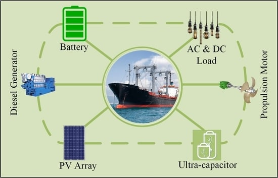
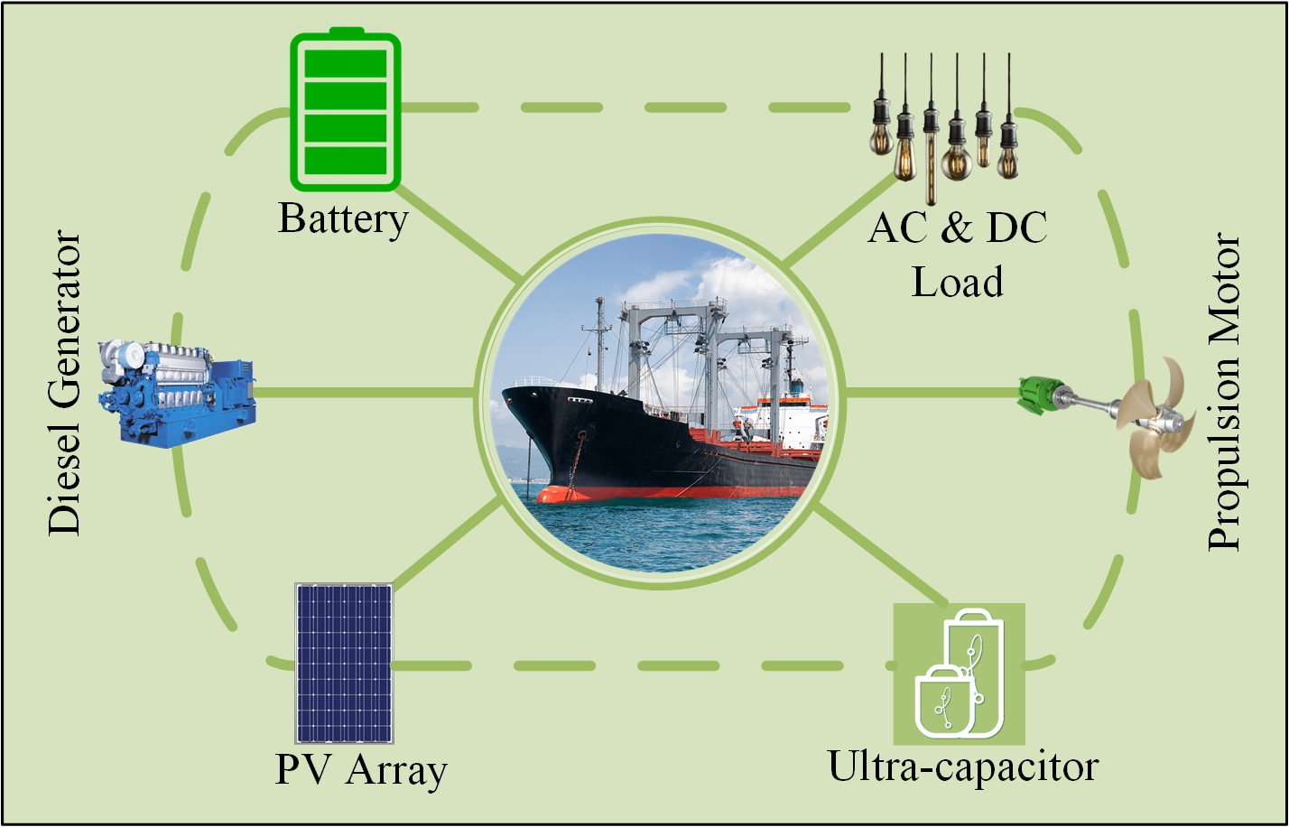
:In recent times, concerns over fossil fuel consumption and severe environmental pollution have grabbed attention in marine vessels. The fast development in solar technology and the significant reduction in cost over the past decade have allowed the integration of solar technology in marine vessels. However, the highly intermittent nature of photovoltaic (PV) modules might cause instability in shipboard microgrids. Moreover, the penetration is much more in the case of utilizing PV panels on ships due to the continuous movement. This paper, therefore, presents a frequency sharing approach to smooth the effect of the highly intermittent nature of PV panels integrated with the shipboard microgrids. A hybrid system based on an ultra-capacitor and a lithium-ion battery is developed such that high power and short term fluctuations are catered by an ultra-capacitor, whereas long duration and high energy density fluctuations are catered by the lithium-ion battery. Further, in order to cater for the fluctuations caused by weather or variation in sea states, a battery energy storage system (BESS) is utilized in parallel to the dc-link capacitor using a buck-boost converter. Hence, to verify the dynamic behavior of the proposed approach, the model is designed in MATLAB/SIMULINK. The simulation results illustrate that the proposed model helps to smooth the fluctuations and to stabilize the DC bus voltage.
1. Introduction
Electrification in marine vessels has been a trend to improve efficiency and minimize emissions [1,2,3,4]. There are severe restrictions imposed by the International Convention for the Prevention of Pollution (MARPOL) from ships [5]. This international convention covers the prevention of pollution of the marine environment by marine vessels. The Kyoto Protocol and Paris Agreement further discuss the reduction of these emissions. The Kyoto protocol was the first to propose limitations on greenhouse emissions and to provide a schedule to prevent from global warming. It was endorsed in 1997 at the Kyoto conference. Further, the Paris agreement was made on the 4th of November 2016. The main motivation of this agreement was to keep the temperature below 2 C and to put further efforts to narrow it down upto 1.5 C [6,7].
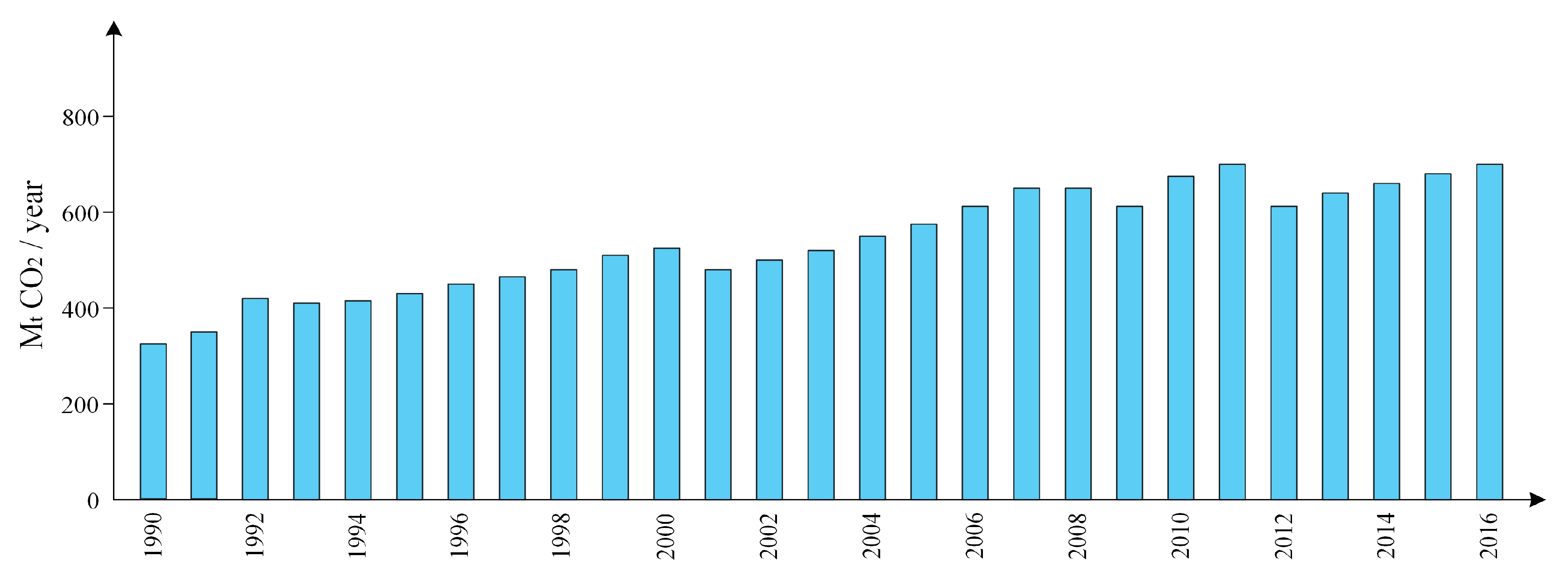
In 2012, the International Marine Organization (IMO) announced that global NOx and SOx emissions from world shipping exhibits approximately 15% and 13%, respectively [8]. Further, it illustrated that for entire international shipping, the CO2 emissions are found to be 2.2% of the global CO2 emissions whereas the CO2 emissions from the entire world shipping is noted to be 2.6%. IMO predicts that by 2050, CO2 emissions from entire international shipping might raise by 50–250%. Figure 1 illustrates CO2 emissions produced by international shipping from 1990 to 2016.
The existing topologies mostly utilized in ships comprise of Battery Energy Storage Systems (BESS) and Hybrid energy storage systems (HESS) typically battery and flywheel. H. Lan et al. used a hybrid model consisting of PV modules, a diesel engine, and flywheel energy storage system (FESS) to improve the power quality and to smooth the fluctuations that are caused by PV systems [9]. The study in [10] proposes a method to determine the optimal sizing of a diesel generator, a PV generation system, and BESS for the shipboard power system to save the fuel and minimize the investment cost and greenhouse emissions. The prototype in [11] consists of a PV module, battery energy storage system, and diesel generation system that can be operated in island mode and grid-connected mode as well. The aim of the hybrid model was to minimize the cost and support the grid in grid-connected mode.
S. Wen et al. propose a hybrid model that comprises of PV generation system, diesel engines, and HESS. The HESS utilized in the study consist of an ultra-capacitor, lead-acid and lithium-ion battery to cater for fluctuation caused by the rolling of ships [12]. In this study, a mathematical model of a PV system is proposed considering the rolling effect of ships. As a PV system on the ship has more fluctuations, HESS is proposed by employing a discrete fourier transform to break down the needed balancing power into several time varying components. Further, a particle swarm-based algorithm is utilized to perform the cost analysis and to optimize the capacity and size of various types of energy storage systems (ESS) used. The study in [13] uses a load profile sharing approach between Li-ion battery and diesel generator to minimize the impact of fluctuations for diesel generator. The high frequency components are allocated to a Li-ion battery whereas low-frequency components are are assigned to diesel generator.
H. Liu et al. propose a mathematical model for PV system considering the integrated motion (basic movement and movement caused by rocking) of a ship and sea conditions [14]. The proposed methodology employed an ultra-capacitor to minimize the fluctuations; hence, ensuring system stability, minimal usage of battery, and an increase in the lifetime of a battery. The study in [15] utilizes a Proportional Integral (PI)-based energy management system to control the charging and discharging of the battery and ultra-capacitor. A low-pass-based filter control is developed to separate the storage reference between ultra-capacitor and battery. This reference power is then sent to a dual active bridge to control the exchange of power between the medium voltage dc system and HESS. J. Tang et al. [16] proposed a HESS comprising a battery and ultra-capacitor with an improved Maximum power tracking (MPPT) algorithm to minimize the intermittency of the PV system. Frequency Hierarchical-based control algorithm is utilized, which assigns low-frequency fluctuations to a battery whereas high-frequency fluctuations are assigned to the ultra-capacitor. Khooban et al. [17] designed an optimal fuzzy based on PD+I load frequency controller for shipboard microgrids. The tuning of the coefficients of the controller is done by a black-hole optimization algorithm to limit the frequency fluctuations. The study in [18] integrated an ultra-capacitor with a PV system to smooth the fluctuations and boost the LVRT capability. The control strategy is designed to attain the scheduling between ultra-capacitor and PV system to minimize the dc-link over-voltage problem. The study in [19] proposed a hybrid system (battery and ultra-capacitor) for shipboard microgrids to support pulse loads and peak demand by using an energy management system based on fuzzy logic. Table 1 shows the list of marine vessels that utilize PV modules.
In order to decrease greenhouse emission and save fuel, numerous solutions have been proposed, for example, wind, solar, waste heat recovery systems, alternative fuels, and hybrid propulsions are among the mostly applied techniques to acquire environmental limitations set by IMO. Although the aforementioned technologies help to reduce emissions and improve fuel efficiency, their intermittent nature or/and slower response requisite the use of ESS such as batteries, flywheel, ultra-capacitor etc. As higher energy and power density cannot be attained by a single energy storage device, novel approaches, for instance, HESS should be investigated for future shipboard microgrids.
In this paper, a PV system is integrated with the shipboard microgrids to minimize the use of fossil fuels and to decrease the greenhouse emission. In order to cater for the highly intermittent nature of PV systems, an ultra-capacitor is hybridized with a Li-ion based battery. The ultra-capacitor energy storage system is utilized as it has higher power density and efficiency as compared to FESS. Among batteries, Li-ion is considered to have high energy and power density. Moreover, a low pass filter and PI-based energy management system is proposed such that high fluctuations will be catered for by the ultra-capacitor whereas low frequency fluctuations are smoothed by the battery. Further, BESS is used in parallel with the dc-link of variable frequency drive (VFD) utilizing a buck-boost converter to cater for the fluctuations caused by the propulsion motor; these fluctuations usually occur due to the variation in the sea conditions and weather. As PV characteristics of a Li-ion battery show that the voltage remains constant, most of the time around 80% in nominal region, the use of a buck-boost converter for this application can be ignored.
The rest of this study is formulated as follows. In Section 2, a comparison of ESS is conducted. The mathematical models are presented in Section 3, followed by modeling of the PV system, battery and ultra-capacitor. Section 4 presents the control strategy for the hybrid PV/UC/battery power system. Section 5 shows the simulation results and verification of the proposed model. Finally, a conclusion is drawn from the study and presented in Section 6.
2. Energy Storage Technologies for Shipboard Microgrids
The energy storage system consists of power an electronics-based converter, energy storage device, and the control mechanism. The popular ESS currently in use for several applications include secondary batteries, Superconducting magnetic energy storage (SMES), ultra-capacitors, Pumped hydro, and Fuel cells (FC). The storage devices aforementioned differ from one another in terms of life-cycle, energy and power density, efficiency, charge, and discharge rate, etc.
2.1. Comparison of Different Energy Storage Technologies
The use of a lead–acid battery was started in the 1890s and is still extensively utilized in those applications in which cost is considered a major problem [32]. It is used in applications such as stand-alone PV system, Uninterruptible Power Supplies, and as a starter in vehicles. These batteries are inexpensive as compared to other types of batteries and have quite low self-discharge (typically 0.3% a day). Moreover, lead can be recyclable and these batteries are available at cheap prices. The main drawback of this sort of battery is its lower energy density, short life-cycle, and hazardousness of lead. On the other hand, Lithium-ion (Li-ion)-based batteries have high nominal voltage of around 3.7 V for each cell as compared to 2 V in case of lead acid batteries [33]. Li-ion-based batteries are more suitable for the application of shipboard microgrids as these batteries have high efficiency, high power and density, and long cycle life as compared to other sort of batteries. The main obstacle is its higher cost and the safety concerns, as metal oxides electrodes are typically unbalanced and can decompose with raise in temperature. In order to cater for this problem, the battery units are prepared with a monetizing unit to evade overcharging and discharging. Table 2 illustrates the technical features of different types of energy storage technologies.
The applications in which high-power density is required for smaller duration, ultra-capacitors and flywheel can be utilized. The main characteristics of ultra-capacitors are their long life-cycle, high power density, faster charging and discharging because of lower internal resistance. The higher cost, sensitivity to over-voltage, and lower energy density limit the use of ultra-capacitor to only those applications that are required with high power for a shorter duration. The pros and cons of ultra-capacitor and Li-ion battery are depicted in Table 3.
2.2. Hybridization of Battery and Ultra-Capacitor
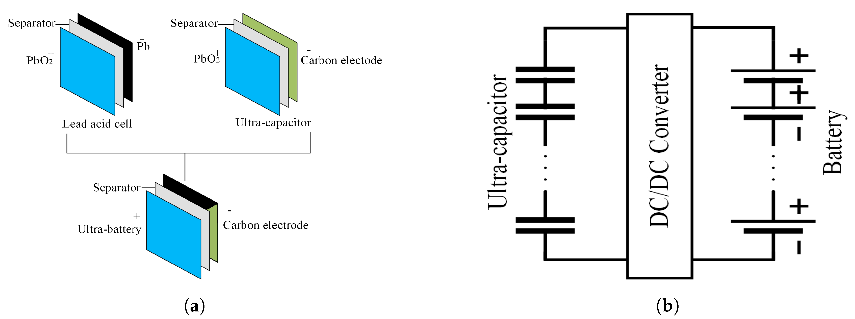
In the literature, HESS consisting of battery and ultra-capacitor has been extensively studied for several applications such as in transportation [42], stand-alone PV [43], and terrestrial microgrids [44]. As high power and high energy density can not be achieved by a single ESS, there is an utmost need to hybridize a higher power density device with a high energy density device. The life-cycle of a battery is found out to be quite low usually in the range of 1500–4500 cycles, and low power density (below 1 kW/kg) whereas an ultra-capacitor has high power density (above 10 kWh/kg) and long life-cycle. Hence, these energy storage technologies can be hybridized. There are two possibilities to hybridize them either internally or externally. In the internal hybridization, the devices are hybridized at the electrode level as depicted in Figure 2a. Ultra-battery is an example of internal hybridization in which lead-acid battery is hybridized with ultra-capacitor [45]. In this study, a hardwire connection is considered as shown in Figure 2b.
3. Model of the Shipboard Microgrid
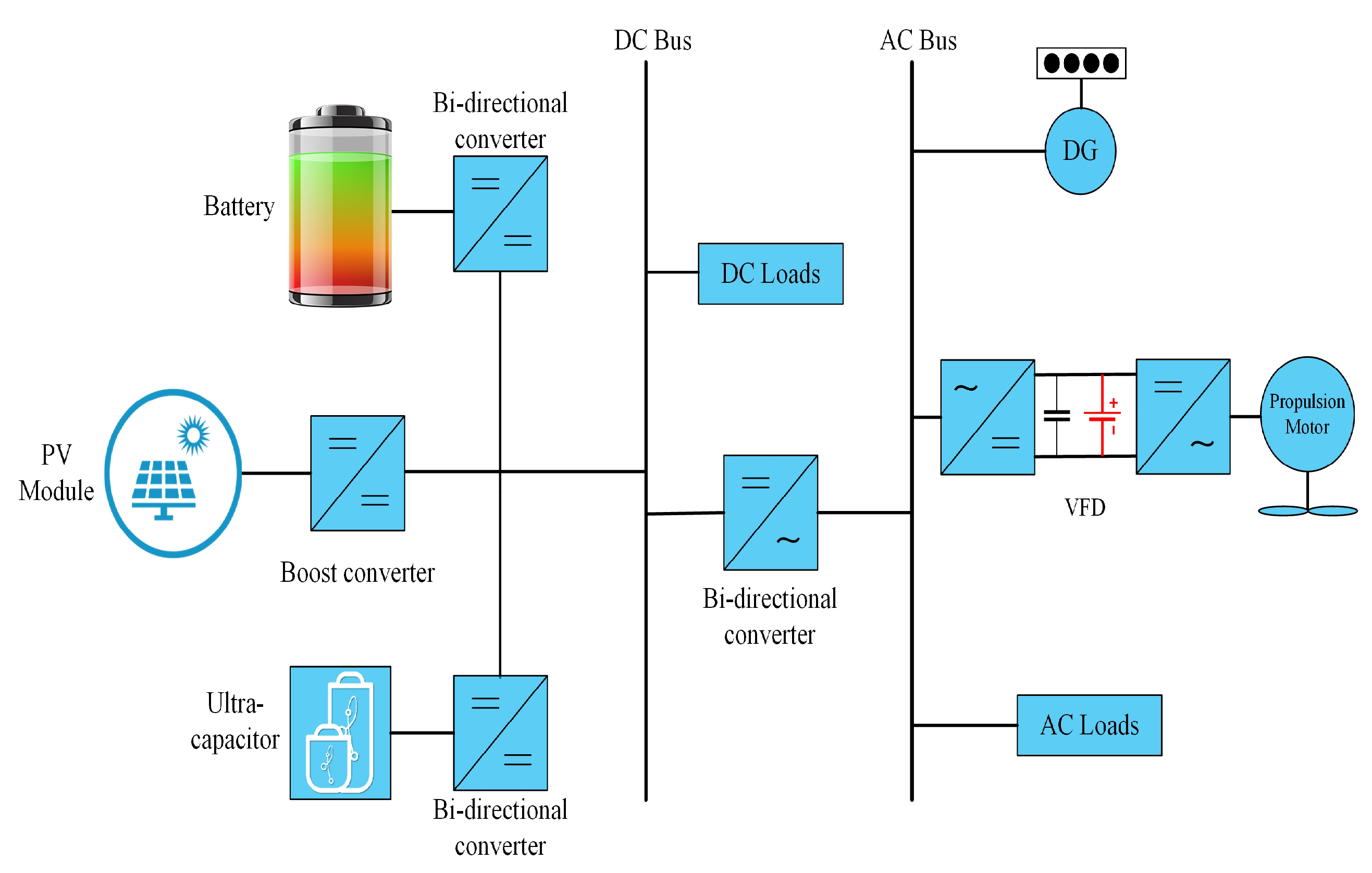
The proposed model depicted in Figure 3 consists of the PV generation system, diesel engine, BESS, ultra-capacitor, boost converter, buck-boost converters, active front end converter, and an inverter. The ultra-capacitor and battery are connected using buck-boost converter in parallel with the dc-link capacitor so it enhances the stability of the shipboard microgrid. The total power flow in the proposed model is depicted in the Equation (1).
The detailed parameters of the synchronous generator, PV system, ultra-capacitor, and Li-ion battery utilized in this paper are given in the Table 4.
3.1. Diesel Engine Modeling
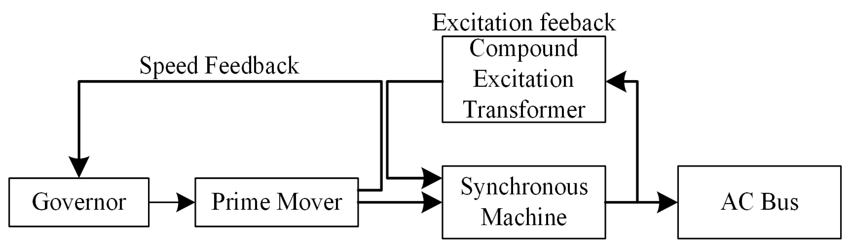
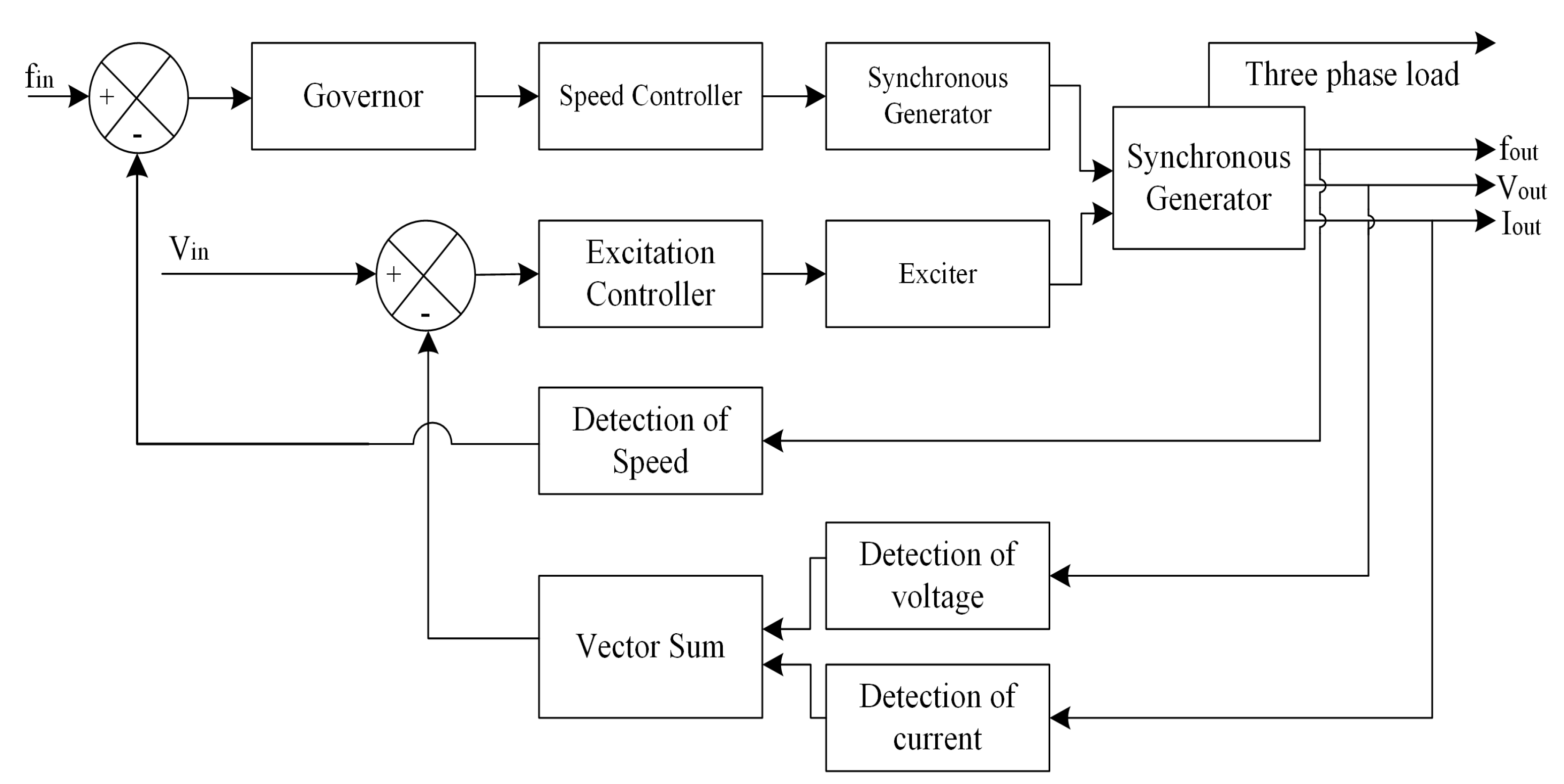
The diesel generator comprises a speed governor, prime mover, compound excitation transformer, and a synchronous generator [49]. The block diagram of a diesel generator set is shown in Figure 4 [50]. The engine’s speed is usually maintained at a fixed speed by using speed governor typically 1500 or 1800 rpm. [51]. The reason for utilizing diesel gen-sets are their relative ease of starting, reliability, compact portability and power density such that their usage is widely spread. In order to control the current and/or voltage, the diesel engine model requires some control mechanisms. The output of the synchronous machine can be controlled by controlling the field current. The excitation system is responsible to provide field voltage Efd for a synchronous machine and is utilized to provide an initial magnetic field to start the synchronous machine as well.
Figure 5 illustrates the speed and excitation feedback control system. The output current and terminal voltage are detected by the compound excitation transformer of excitation feedback system and the speed of the generator is detected by speed feedback. In the past, mechanical governors were utilized but due to errors, such as large inherent droop, they were replaced with electric governors. All blocks in an electronic governor are electrical excluding the actuator block. Hence, higher accuracy can be achieved and a droop of 0.5% is observed in contrast to 4% in mechanical governors.
3.2. PV System Modeling
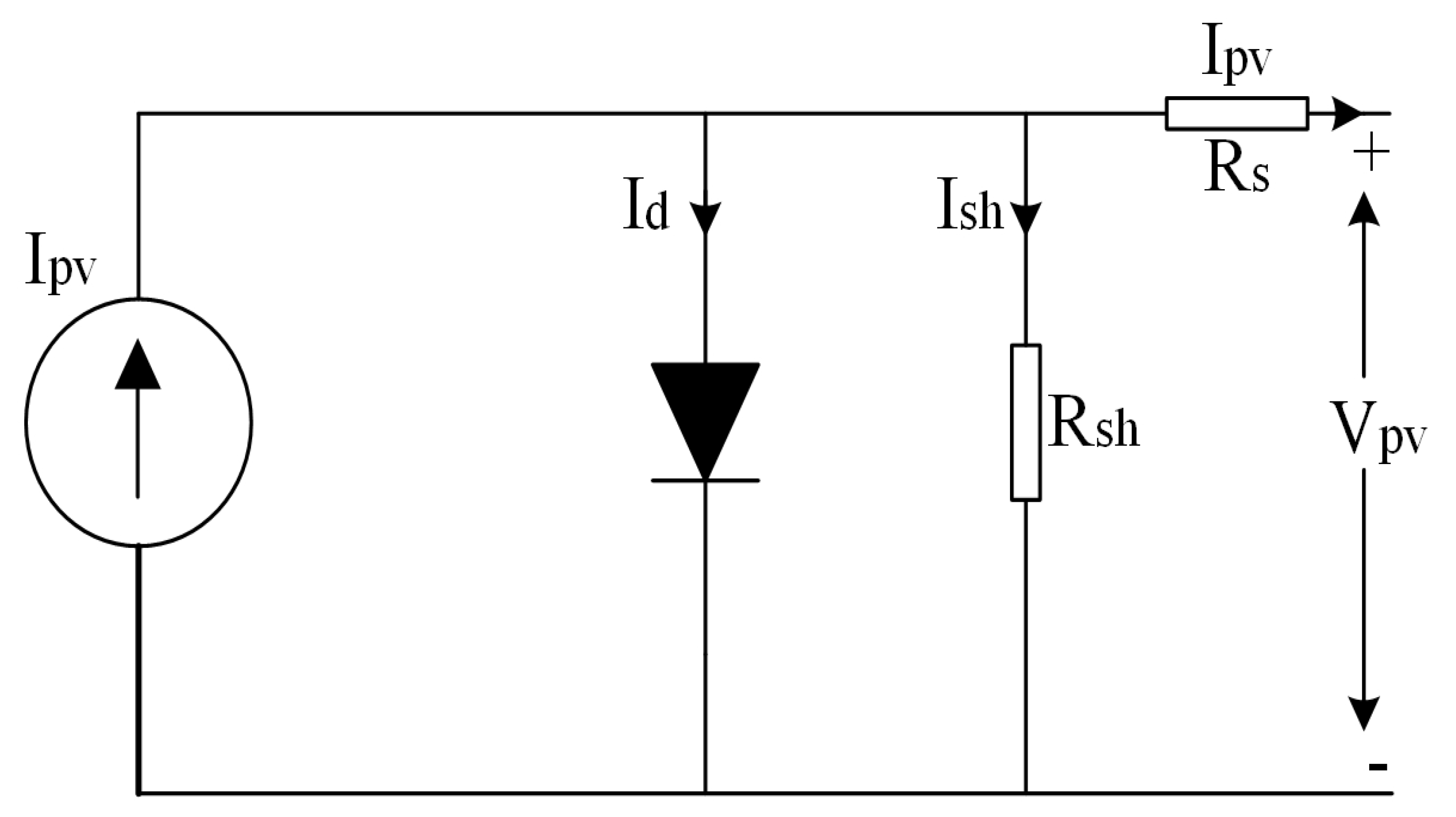
The PV model in the Simulink library is utilized in this paper; the PV source comprises of several strings of PV modules linked in parallel whereas each string contains the number of series PV modules as well. The equivalent circuit of a PV module based on an electrical system is illustrated in Figure 6 [52]. The mathematical model of a PV module can be expressed by the Equations (2)–(7).
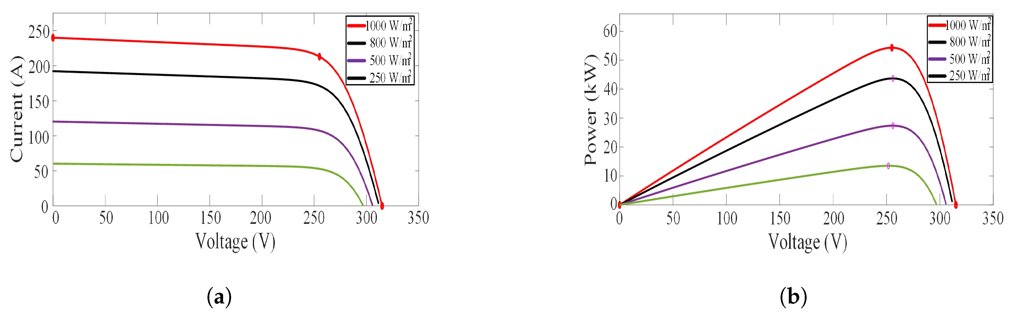
The PV characteristic curve of PV module with specified temperature (25 C) and varying irradiance is shown in Figure 7 where Figure 7a illustrates the I-V characteristic and Figure 7b shows the P-V characteristics of solar array.
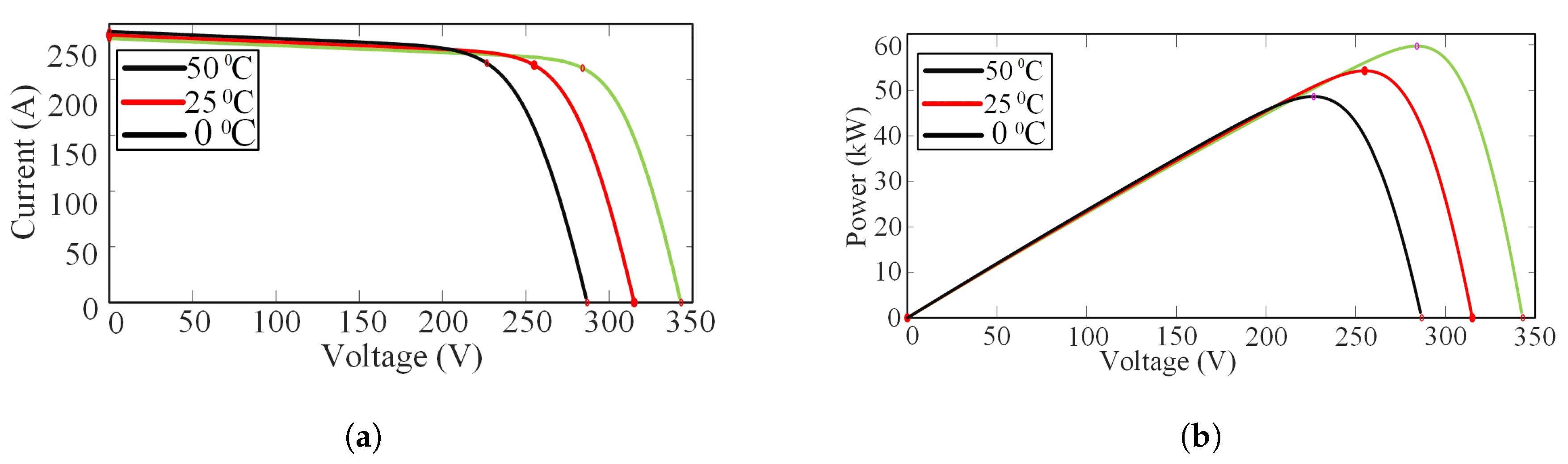
The characteristic curve at varying temperature and specified irradiance (1000 W/m2) is depicted in Figure 8 where Figure 8a illustrates the I-V characteristic and Figure 8b shows the P-V characteristics of solar array.
The efficiency of a PV module can be maximized using maximum power pint (MPPT)-based algorithms. In this paper, a Perturb and observe (P & O)-based algorithm is utilized due to the simplicity of the method and its accuracy of tracking. The P & O algorithm tracks the MPPT by increasing or decreasing the voltage repeatedly at the MPPT of the PV system. The inputs to the MPPT algorithm are the output current (Ipv) and voltage (Vpv) of PV module. The flow chart of P & O algorithm is illustrated in Figure 9. In order to implement this methodology, the voltage and current of PV modules must be initially measured [53]. The output of the P & O algorithm is the estimated MPPT voltage (Vmp), which is utilized to control DC–DC converter in order to attain continuously PV source open-circuit voltage.
3.3. Battery Modeling
The battery models are categorized mainly as an electric circuit model and electrochemical model, the rest of the models are usually derived from these; for instance: a dynamic battery model that is derived from a combination of an electrochemical and an electrical model. Some researchers further categorized this as an analytical and mathematical model [54]. The former one is based on the empirical data such as Peukert’s equation, which involves integrating current to improve the model of a battery. On the other hand, the latter is a simplified electrochemical model like, for instance, Stepherd’s equation. The reason for utilizing a mathematical model in this paper is the high efficiency and cost-effective tools such as MATLAB/SIMULINK [55].
Physics-based, empirical, and semi-empirical models have been proposed in the literature to diagnose the aging effect and its impact on the life time of a battery [56]. This paper did not take into consideration the temperature effect, aging effect, and degradation of a Li-ion battery. The calendar aging is an important factor especially in transportation applications and is considered for future work. The reason for utilizing a Li-ion battery in this paper is because of its low maintenance cost, lower self-discharge, high energy and power density in comparison with other batteries. The charge and discharge model of a Li-ion battery is illustrated in the Equations (8) and (9) respectively.
3.3.1. Charge Model (il) < 0
For Li-ion battery the charging model is shown in following equation:
3.3.2. Discharge Model (il) > 0
For Li-ion battery the discharging model is shown in following equation:
The SOC and efficiency of the battery in terms of charge and discharge can be defined as:
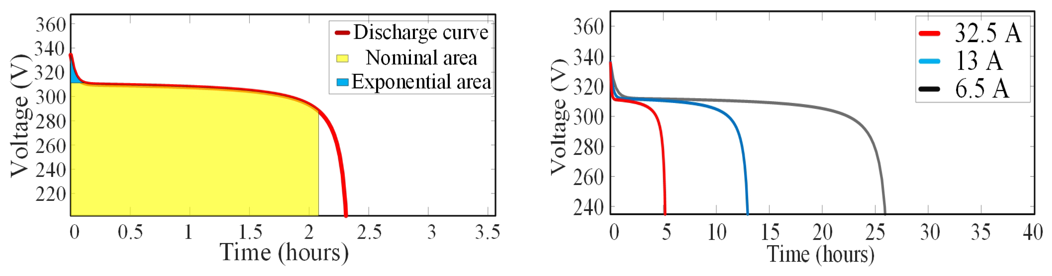
The discharge characteristics of a Li-ion-based battery is shown in Figure 10. This type of battery has a flat voltage curve in the usable discharge range. The discharge characteristics are divided into three parts: nominal region, exponential region, and discharge curve. In the exponential region, voltage drops in a very fast manner whereas the mid point voltage is the nominal voltage of the battery during charging and discharging and if this curve is flatter and shows that there will be less variation in voltage. The fully charged voltage is higher than nominal voltage whereas when it reaches end of life, the voltage will be less than mid point voltage.
3.4. Ultra-Capacitor Modeling
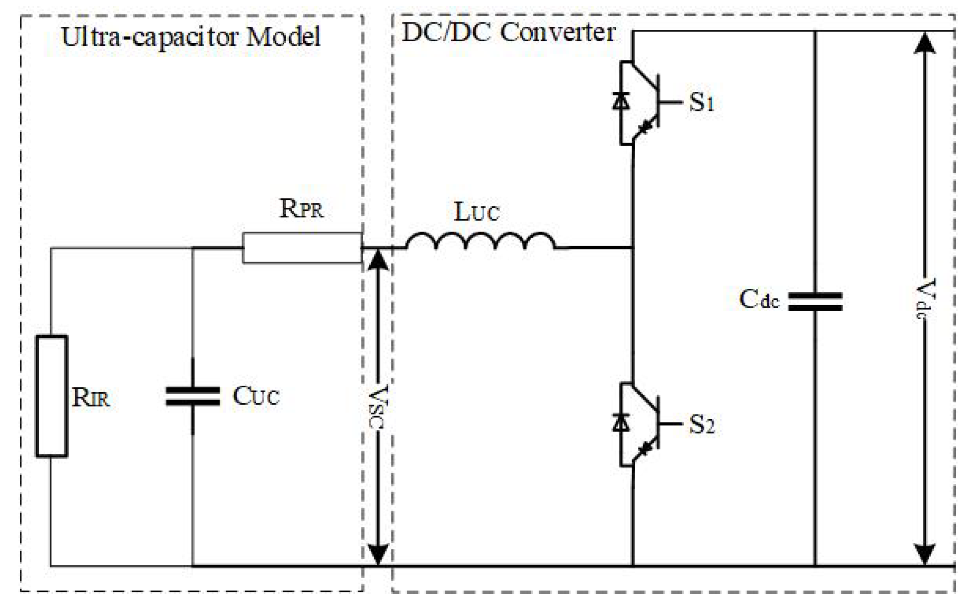
The configuration of the ultra-capacitor utilized in this study is depicted in Figure 11 which comprises an ultra-capacitor model and a DC–DC converter. This model is the combination of equivalent internal resistance (RIR), equivalent parallel resistance (RPR), and capacitance of an ultra-capacitor. The configuration acts as a boost converter in discharging mode whereas the buck converter in the charging mode. As the response time of the ultra-capacitor is very fast and has the capability to smooth the fluctuations produced by the highly intermittent nature of the PV modules, especially when it is integrated with the shipboard microgrids as compared to terrestrial microgrids.
The output voltage of an ultra-capacitor can be expressed in terms of Stern’s equation as expressed in Equation (10).
4. Control Strategy of Hybrid Shipboard Microgrids
4.1. Active Front End Converter
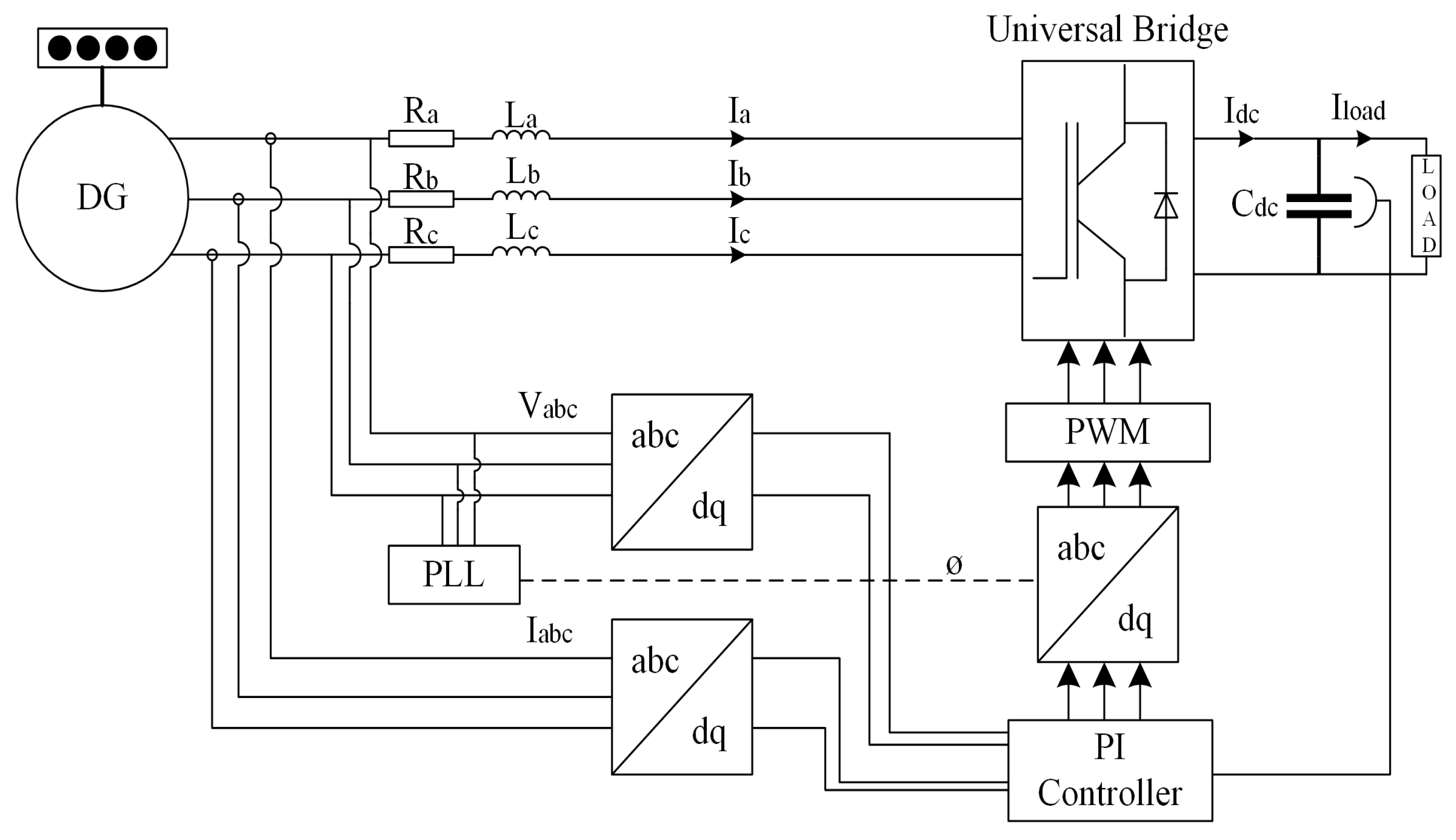
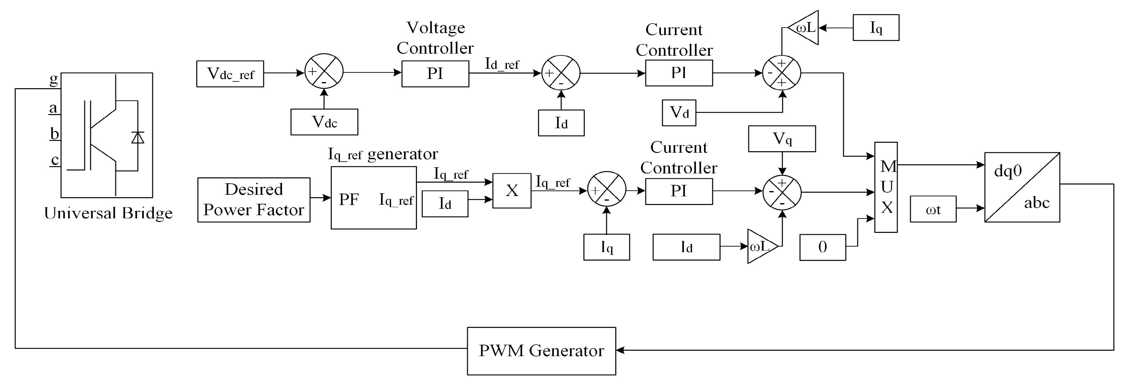
A rectifier is usually a six-pulse-type as it consists of six diodes and is found to be a cost-effective approach to convert Alternating current (AC) power into Direct Current (DC). This approach produces harmonics into the shipboard power system, which results in an additional heat and losses. One of the possible approaches is to use multiple-rectifiers like 12-pulse, 18-pulse, etc. to minimize the harmonics but this approach increases the cost due to an increase in the number of diodes. Another approach is to add passive filters that inject low impedance into the power system to absorb harmonic frequencies, but the disadvantage of this approach is that a passive filter utilizes more energy and takes a large amount of space. An active front end converter is utilized in this study and it is an effective approach that minimizes the total harmonic distortion, flexible regulation of dc-link voltage, provides unity power factor, and relatively sinusoidal input currents [57]. The block diagram of the active front with the control mechanism is illustrated in Figure 12.
In this technique, instead of utilizing diodes to convert AC into DC, insulated bipolar transistors (IGBTs) are used. The total harmonics in this approach are reduced to 3%, which in the conventional diode rectifier approach are around 25–30%. The schematic of the implemented control strategy of three-phase active front end converter is implemented in MATLAB/Simulink, and is depicted in Figure 13. At first, the dc-link voltage (Vdc) is compared with the reference value (Vdc_ref) and then the error is fed to the outer loop of PI controller. The output of the controller is Id_ref which corresponds to the active power of the converter. The input reactive power of the active front end converter is adjusted by setting the current reference of q-axis (Iq) to 0 to achieve power factor equals to 1.
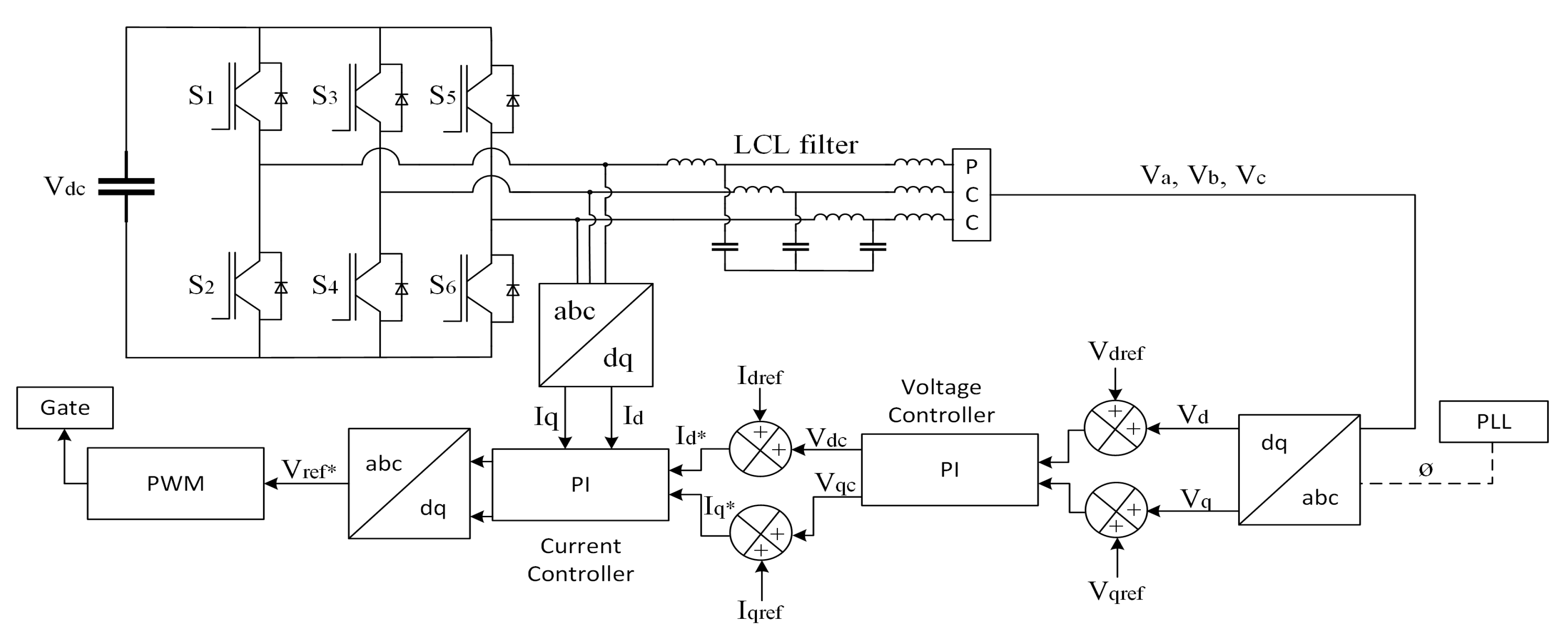
4.2. Inverter Control
The control strategy applied for an inverter consists of two control loops, the outer loop which is pledged to control dc-link voltage whereas the inner loop is pledged to control grid current as illustrated in Figure 14. The current loops further solves power quality issues such as improved power factors and low THD. On the other hand, the voltage control loop is helpful in balancing the flow of power in the system. D-q control or synchronous reference frame-based control uses a reference frame transformation abc to dq (current park transformation and voltage park transformation), which transforms the voltage and current into a d-q frame. The transformed current is helpful in controlling the grid current whereas voltage detects frequency and phase of the grid. Therefore, the control variables are converted to dc values, hence, controlling and filtering become easier. (Vd_ref) and (Vq_ref) are the voltages in dq frame whereas to generate the gate signal for voltage source inverter, pulse width modulation (PWM) is utilized.
4.3. Frequency Sharing Control
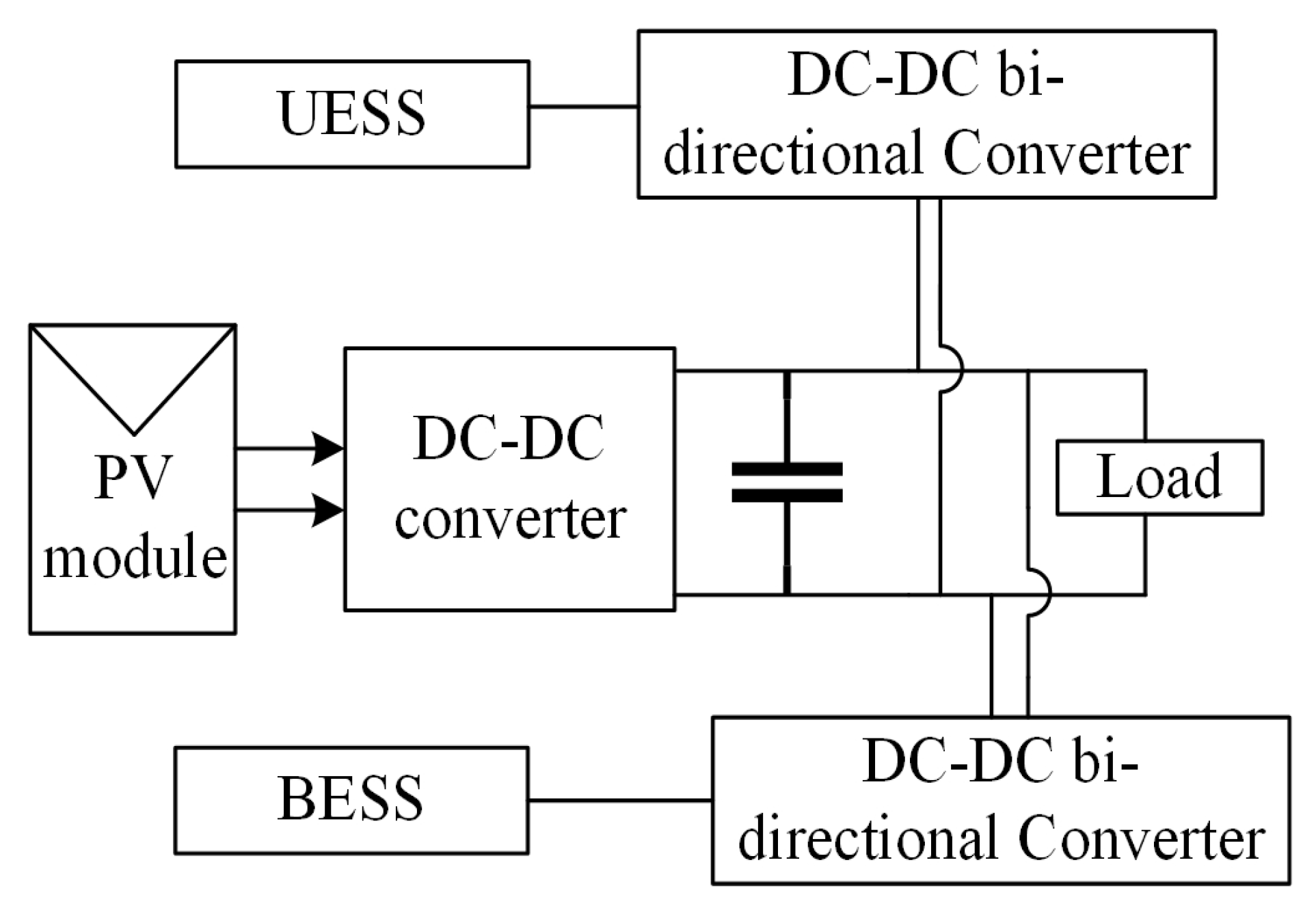
The proposed methodology is based on the frequency sharing approach in which load is shared between low and high-frequency components. The high-frequency components are catered by ultra-capacitor whereas low-frequency components are handled by the Li-ion battery. The block diagram of such an approach is illustrated in Figure 15.
The proposed energy management strategy relies on the frequency sharing approach. In this methodology, the load current is shared between high and low frequency components by the use of a low pass filter as expressed below:
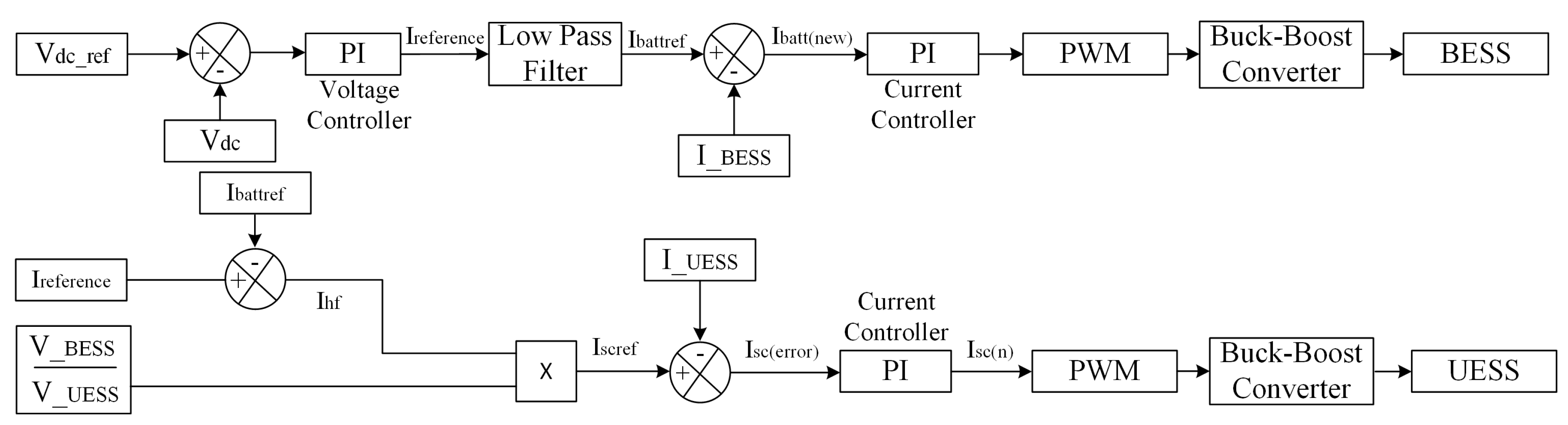
The Simulink model of the proposed approach is illustrated in Figure 16. The dc-link voltage of a PV module is compared with the reference dc voltage and is then fed to an outer loop voltage controller. The lower frequency components are then fed into an inner current loop and the signal is then fed to PWN which sends the gate signal to the dc-dc converter of a battery. On the other hand, ultra-capacitors are known by their higher power density and faster response. Therefore, higher frequency fluctuations will be catered by the ultra-capacitor. The inner current loop will send a signal by PWM to the gate of ultra-capacitor. The control strategy for such an approach can be expressed by Equations (11)–(13).
5. Simulation and Verification
The hybrid PV/Diesel/Battery/Ultra-capacitor model illustrated in Figure 3 is selected to test the proposed control approach. The approach adopted in this paper is categorized into two cases to show the effectiveness of the proposed approach. In the first case, due to the intermittent nature of PV systems, ultra-capacitor and Li-ion battery are hybridized to cater for the fluctuations. On the other hand, in the second case, BESS is used in parallel with the dc-link capacitor of VFD to mitigate the fluctuations caused by variation in sea conditions or due to weather.
5.1. Case 1
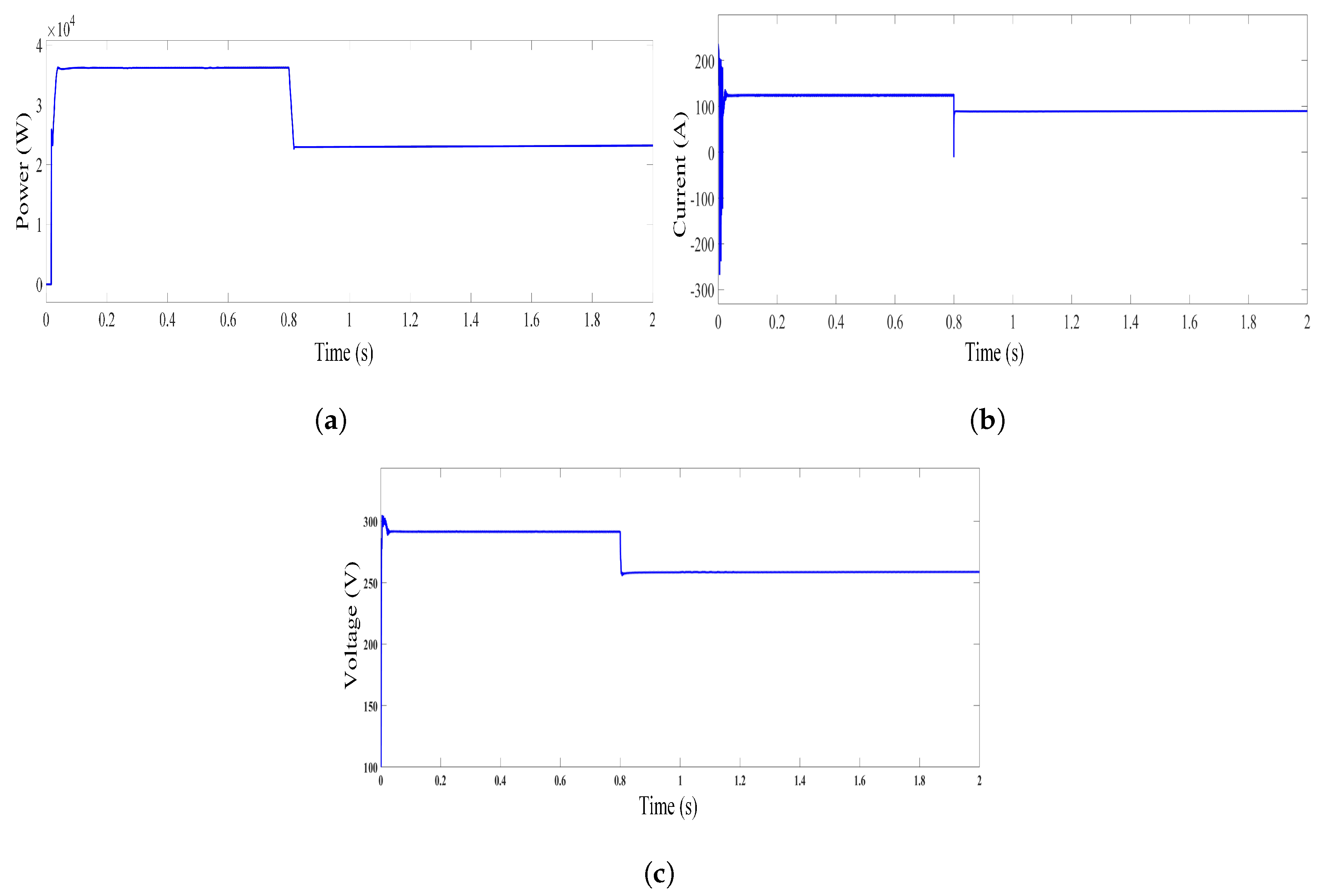
In the first case, as discussed before, the PV systems show more fluctuations in scenarios of integration with a shipboard microgrid due to the movement of ships and other factors such as moisture, weather, etc. The Li-ion battery and ultra-capacitor are hybridized and are integrated with the output of PV modules using dc-dc converter in parallel to the dc-link capacitor. In this study, at the start irradiation is set to be maximum and is varied at 0.8 s to check the effectiveness of the proposed approach. Figure 17a illustrates the variation in power, Figure 17b refers to the current, and Figure 17c shows the voltage with the variation in irradiance.
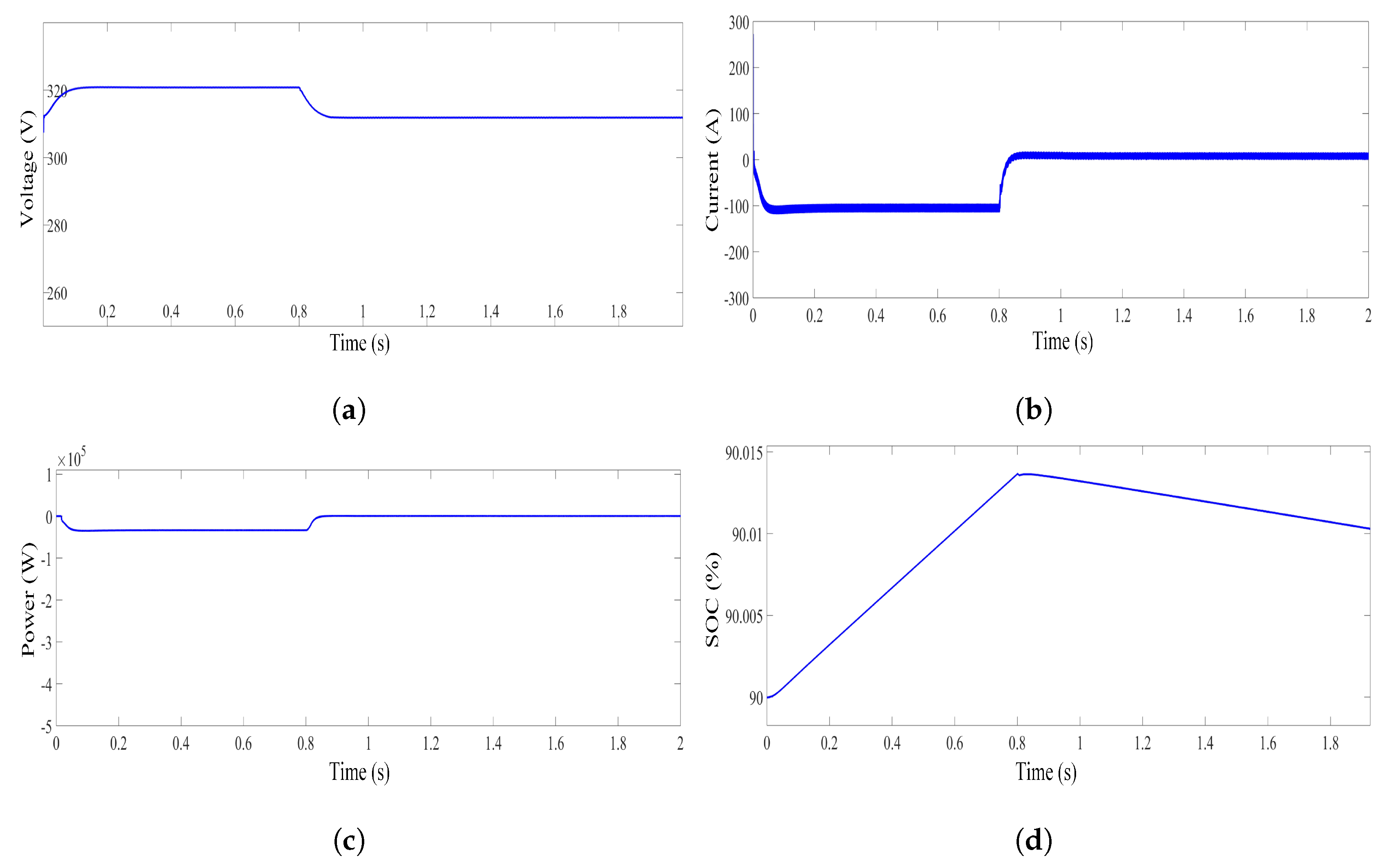
A Li-ion-based battery is utilized in this study to cater for the low-frequency fluctuations. It can be inferred from Figure 18a–c, that at 0.8 s, there is a decrease in voltage, current, and power that show the variation in irradiance. Hence, the battery is providing the power to maintain the voltage at DC-link. It can be further observed from Figure 18d that the battery is getting charged at the start as the irradiance of the solar panel at that instant is considered to be maximum. At 0.8 s, due to variation in irradiance, the battery starts to support due to which the battery drains and ultimately the SOC of the battery decreases.
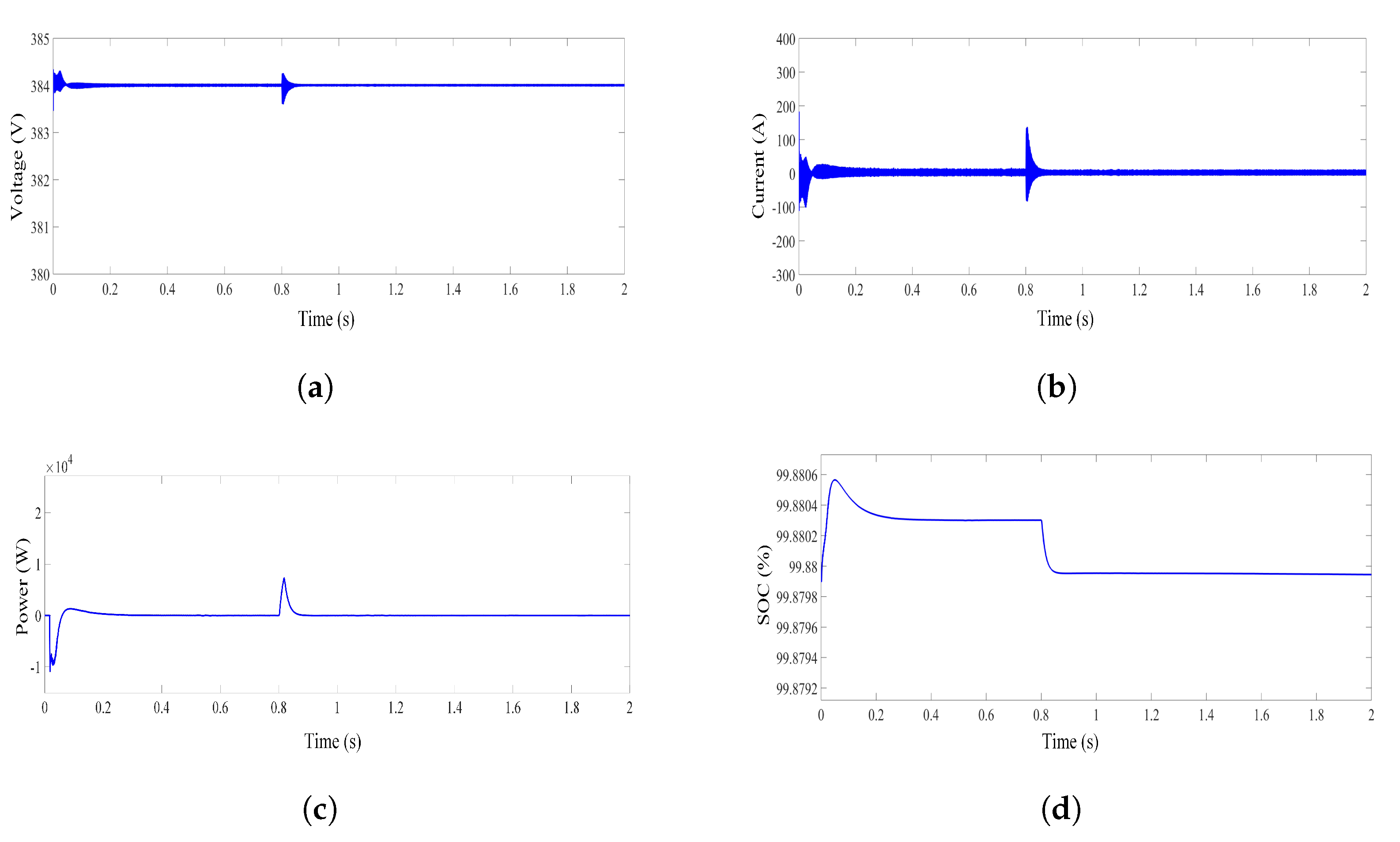
The ultra-capacitor is hybridized with the battery to cater for the higher frequency fluctuations. It can be inferred from Figure 19a–c, that at 0.8 s there is sudden decrease in voltage, current, and power that illustrates the variation in irradiance. In the start, SOC of the ultra-capacitor is constant as its fully charged. At 0.8 s due to sudden variation in irradiance, fluctuation is observed. The ultra-capacitor is responsible to cater for the high-frequency fluctuation. It can be seen from Figure 19d that SOC of the ultra-capacitor suddenly decreases and remain constant for the rest of the period as the battery is responsible to cater for rest of the duration.
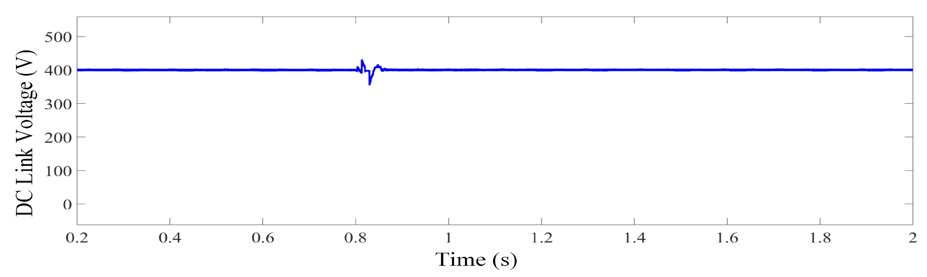
Figure 20 illustrates the dc-link voltage, the variation in the generation of power from PV panel at 0.8 s is observed depicting the change in irradiance, which is catered by the hybrid energy storage system.
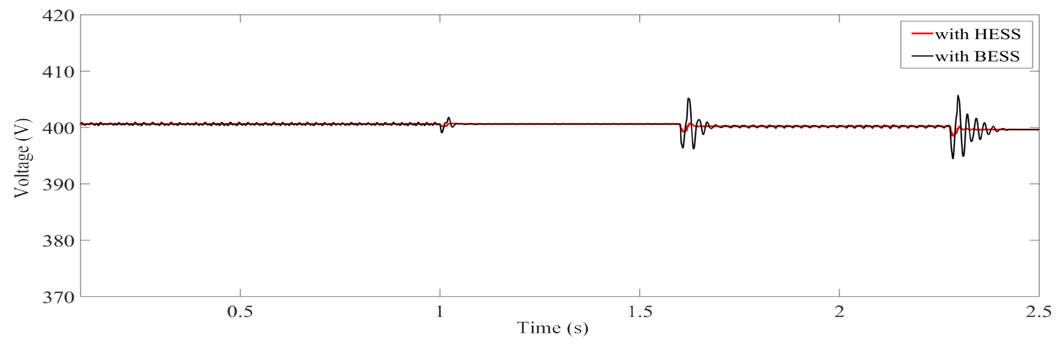
Figure 21 shows the comparison of stabilizing the dc-link voltage with varying irradiance by using proposed approach in comparison to earlier approach to stabilize dc-link voltage by using BESS only.
5.2. Case 2
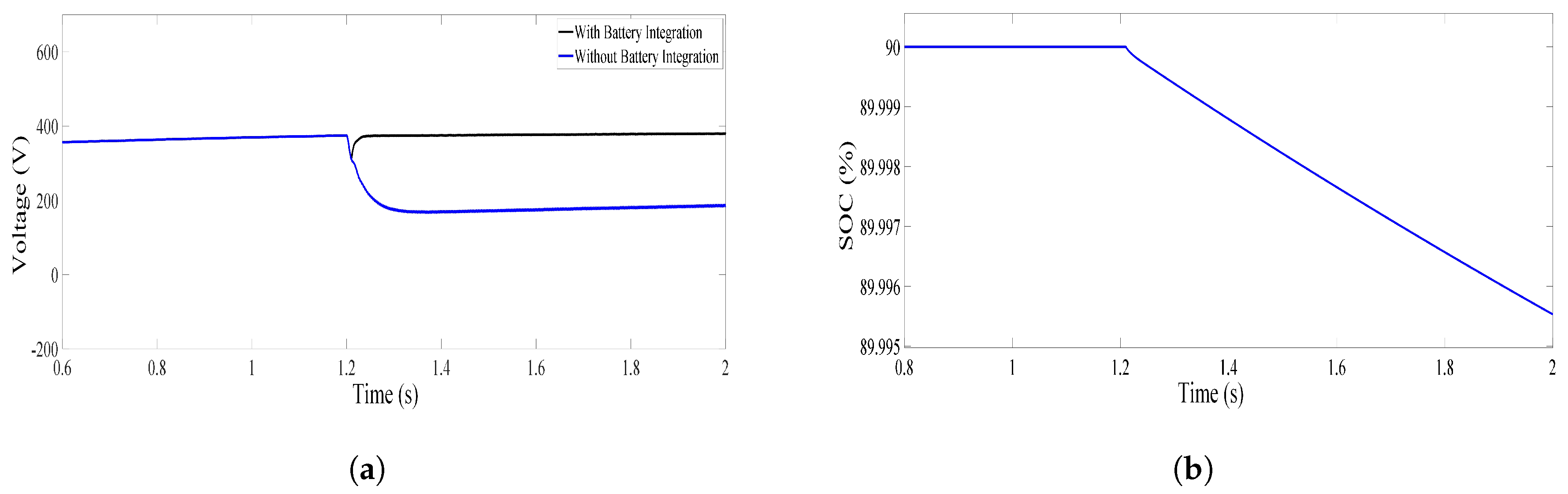
In the second case, to cater for the fluctuations caused by the propulsion motors due to variation in sea states which ultimately causes variation in power requirement, the battery is integrated in parallel with the dc-link capacitor using a buck-boost converter. It can be inferred from Figure 21a, that at 1.2 s the fluctuation is observed and it is catered by the BESS. On the other hand, Figure 22b illustrates that the SOC of BESS starts to decrease at 1.2 s.
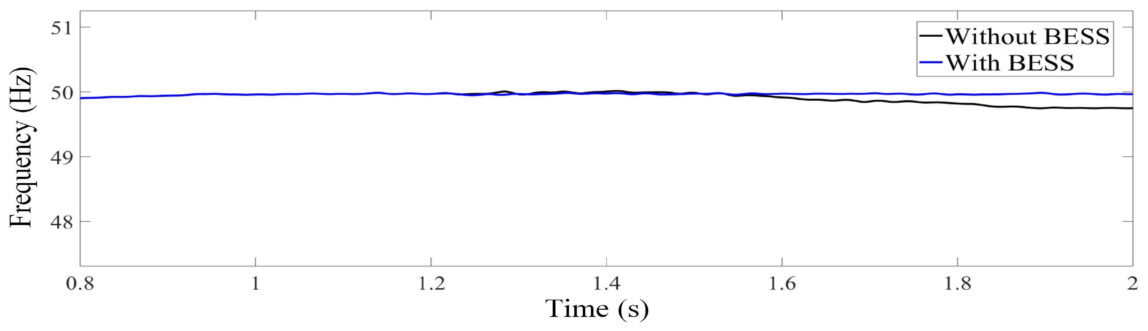
Due to the impact of variation in power demand, there is variation in frequency observed and is depicted in Figure 23, it is observed that at 1.2 s the frequency starts to decrease due to the variation in load and is catered by BESS.
The comparison between different approaches in the literature are presented in Table 5. Although in literature few researchers focused on frequency sharing approach for shipboard microrgids, some of them shared the frequency components between BESS and DG that ultimately adds burden on the DG. Few researches utilize sole energy storage such as flywheel or ultra-capacitor to minimize the fluctuations caused by PV systems, but these ESS devices can smooth or mitigate short term fluctuations only. Other techniques utilized fuzzy-based control and optimization algorithms for sizing several ESS, stabilizing dc-link voltage and reducing emissions, etc. The proposed approach in this study utilizes PI-based control for frequency sharing between BESS and an ultra-capacitor. The PI-based methodology employed in this work has less complexity and is often employed for industrial applications.
6. Conclusions
In this paper, a hybrid PV/Diesel/Battery/Ultra-capacitor is modeled and a control strategy based on a PI controller is developed. The PV panels behave differently when they are integrated with shipboard microgrids due to the movement and rolling of a ship. Therefore, there is an utmost need to integrate an ultra-capacitor to shipboard power systems to smooth the fluctuations that are caused by the highly intermittent nature of solar panels. In this study, the load current is shared on the basis of different frequency components to smooth the power. The simulation results show the effectiveness of the proposed hybrid model as they help to minimize the fluctuation. It can be inferred that an ultra-capacitor-based energy storage system is responsible to cater for the high-frequency fluctuations due to the faster response, whereas a battery is responsible to mitigate the low-frequency components because of its slow response. Moreover, battery life-time can be increased by handling short-term fluctuations through the ultra-capacitor. Further, in the second case, the integration of a battery in parallel with the dc-link capacitor helps to mitigate the fluctuations caused by either variation in sea conditions or due to weather. Future work will be based on a case study of a yacht by considering the impact of partial shading effect and to validate the proposed approach; it will be implemented on a hardware in loop setup.
Author Contributions
M.U.M. has written the original draft and performed the simulations; Y.T. contributed in terms of methodology and validation; , K.A.K.N. and F.K. were involved in Writing, reviewing & editing, J.C.V. and J.M.G. supervised this study and corrected the manuscript.
Funding
This research received no external funding.
Conflicts of Interest
The authors declare no conflict of interest.
Abbreviations
The following abbreviations are used in this manuscript:
| PV | Photovoltaic |
| IMO | International marine organization |
| ESS | Energy storage system |
| HESS | Hybrid energy storage system |
| IPS | Integrated power system |
| VFD | Variable frequency drives |
| PI | Proportional Integral |
| BESS | Battery energy storage system |
| FESS | Flywheel energy storage system |
| UC | Ultra-capacitor |
| DG | Diesel generator |
| MOPSO | Multi-Objective Particle Swarm Optimization |
| PSO | Particle swarm optimization |
| MPC | Model predictive control |
| LFC | Load frequency control |
| Ipv | Solar generated current at the nominal condition (25 C and 1000 W/m2) |
| Ir | Solar radiation (W/m2) |
| Isc | Short circuit current (A) |
| Ki | Short circuit current of the cell |
| IRs | Reverse saturation current of PV module |
| q | charge of an electron |
| Voc | Open circuit voltage (V) |
| Ns | Number of cells in series |
| n | The ideality factor of diode |
| k | Boltzmann’s constant |
| Io | Saturation current of a PV module |
| Tr | Nominal temperature |
| Ego | Band gap energy of a semiconductor |
| Vt | Thermal voltage of diode (V) |
| Rsh | Shunt resistance (Ω) |
| Ns | Number of modules connected in series |
| Np | Number of modules connected in parallel |
| I | output current of PV module (A) |
| it | Extracted capacity (Ah) |
| i | battery current (A) |
| il | Low frequency current dynamics (A) |
| Eo | Constant voltage (V) |
| K | Polarization constant (V/Ah) |
| Q | Maximum battery capacity (Ah) |
| A | Exponential voltage (V) |
| B | Exponential capacity (Ah−1) |
| Co | Capacity of battery |
| Efficiency of converter | |
| Ai | Interfacial area between electrolyte and electrode |
| QT | Electric charge |
| Permittivity of material | |
| Permittivity of free space | |
| D | Molecular radius |
| R | Ideal gas constant |
| T | Operating temperature |
| F | Faraday constant |
| c | molar concentration |
| RUC | Total resistance of UC |
| iUC | UC current |
References
- McCoy, T.J. Electric ships past, present, and future technology leaders. IEEE Electrif. Mag. 2015, 3, 4–11. [Google Scholar] [CrossRef]
- Zahedi, B.; Norum, L.E.; Ludvigsen, K.B. Optimized efficiency of all-electric ships by dc hybrid power systems. J. Power Sour. 2014, 255, 341–354. [Google Scholar] [CrossRef]
- Doerry, N. Naval Power Systems: Integrated power systems for the continuity of the electrical power supply. IEEE Electrif. Mag. 2015, 3, 12–21. [Google Scholar] [CrossRef]
- Doerry, N.; Amy, J.; Krolick, C. History and the status of electric ship propulsion, integrated power systems, and future trends in the US Navy. Proc. IEEE 2015, 103, 2243–2251. [Google Scholar] [CrossRef]
- The International Convention for the Prevention of Pollution from Ships. Available online: http://www.imo.org/en/About/Conventions/ListOfConventions/Pages/International-Convention-for-the-Prevention-of-Pollution-from-Ships-%28MARPOL%29.aspx (accessed on 5 June 2019).
- Rogelj, J.; Den Elzen, M.; Höhne, N.; Fransen, T.; Fekete, H.; Winkler, H.; Schaeffer, R.; Sha, F.; Riahi, K.; Meinshausen, M. Paris Agreement climate proposals need a boost to keep warming well below 2 ∘C. Nature 2016, 534, 631. [Google Scholar] [CrossRef]
- EU Commission: The Paris Protocol—A Blueprint for Tackling Global Climate Change Beyond 2020. Available online: https://www.eesc.europa.eu/sites/default/files/resources/docs/15_362-ppaper_changement-clim_en.pdf (accessed on 27 August 2018).
- International Maritime Organization: Prevention of Air Pollution from Ships. Available online: http:// www.imo.org/en/OurWork/Environment/PollutionPrevention/AirPollution/Pages/Air-Pollution.aspx (accessed on 5 June 2019).
- Lan, H.; Bai, Y.; Wen, S.; Yu, D.; Hong, Y.Y.; Dai, J.; Cheng, P. Modeling and stability analysis of hybrid pv/diesel/ess in ship power system. Inventions 2016, 1, 5. [Google Scholar] [CrossRef]
- Lan, H.; Wen, S.; Hong, Y.Y.; David, C.Y.; Zhang, L. Optimal sizing of hybrid PV/diesel/battery in ship power system. Appl. Energy 2015, 158, 26–34. [Google Scholar] [CrossRef] [Green Version]
- Lee, K. J.; Shin, D.; Yoo, D.W.; Choi, H.K.; Kim, H. J. Hybrid photovoltaic/diesel green ship operating in standalone and grid-connected mode–Experimental investigation. Energy 2013, 49, 475–483. [Google Scholar] [CrossRef]
- Wen, S.; Lan, H.; Yu, D.C.; Fu, Q.; Hong, Y.Y.; Yu, L.; Yang, R. Optimal sizing of hybrid energy storage sub-systems in PV/diesel ship power system using frequency analysis. Energy 2017, 140, 198–208. [Google Scholar] [CrossRef]
- Bellache, K.; Camara, M.B.; Dakyo, B. Hybrid Electric Boat based on variable speed Diesel Generator and lithium-battery-using frequency approach for energy management. In Proceedings of the 2015 International Aegean Conference on Electrical Machines & Power Electronics (ACEMP), 2015 International Conference on Optimization of Electrical & Electronic Equipment (OPTIM) & 2015 International Symposium on Advanced Electromechanical Motion Systems (ELECTROMOTION), Side, Turkey, 2–4 September 2015; pp. 744–749. [Google Scholar]
- Liu, H.; Zhang, Q.; Qi, X.; Han, Y.; Lu, F. Estimation of PV output power in moving and rocking hybrid energy marine ships. Appl. Energy 2017, 204, 362–372. [Google Scholar] [CrossRef]
- Khan, M.M.S.; Faruque, M.O. Management of hybrid energy storage systems for MVDC power system of all electric ship. In Proceedings of the 2016 North American Power Symposium (NAPS), Denver, CO, USA, 18–20 September 2016; pp. 1–6. [Google Scholar]
- Tang, J.; Xiong, B.; Huang, Y.; Yuan, C.; Su, G. Optimal configuration of energy storage system based on frequency hierarchical control in ship power system with solar photovoltaic plant. J. Eng. 2017, 13, 1511–1514. [Google Scholar] [CrossRef]
- Khooban, M.H.; Dragicevic, T.; Blaabjerg, F.; Delimar, M. Shipboard microgrids: A novel approach to load frequency control. IEEE Trans. Sustain. Energy 2017, 9, 843–852. [Google Scholar] [CrossRef]
- Qiu, Y.; Yuan, C.; Tang, J. Integrating SCESS into a Ship-PV Power System to Mitigate Power Fluctuations and Improve LVRT Capability. Arab. J. Sci. Eng. 2019, 44, 1–13. [Google Scholar] [CrossRef]
- Khan, M.M.S.; Faruque, M.O.; Newaz, A. Fuzzy logic based energy storage management system for MVDC power system of all electric ship. IEEE Trans. Energy Convers. 2017, 32, 798–809. [Google Scholar] [CrossRef]
- Solar-Powered Super Yacht (E-Boat). Available online: http://www.aideenergy.com/index.php?option=module&lang=en&task=showlist&id=74 (accessed on 5 June 2019).
- Greeline 33 Yacht. Available online: https://inoffice.app.box.com/v/greenlineyachtsbrochure (accessed on 5 June 2019).
- Grrenline 39. Available online: https://www.greenlinehybrid.si/yacht/greenline-39/ (accessed on 5 June 2019).
- Greenline 40. Available online: https://www.greenlinehybrid.si/yacht/greenline-40/ (accessed on 5 June 2019).
- Duffy London. Available online: https://duffylondon.com/product/archivenew/solaris-global-cruiser-2/ (accessed on 5 June 2019).
- Silent 80 Yacht. Available online: https://www.silent-yachts.com/silent80/ (accessed on 5 June 2019).
- Silent 64 Yacht. Available online: https://www.silent-yachts.com/silent64/ (accessed on 5 June 2019).
- Silent 55 Ferry. Available online: https://www.silent-yachts.com/silent55-ferry/ (accessed on 5 June 2019).
- PlanetSolar, Solar-Powered Ship. Available online: https://www.ship-technology.com/projects/planetsolar/ (accessed on 5 June 2019).
- Aquarius Eco Ship: Low Emission Green Ship Concept Design with Rigid Sails & Solar Power. Available online: https://www.ecomarinepower.com/en/aquarius-eco-ship (accessed on 5 June 2019).
- M/V Auriga Leader. Available online: https://www.marineinsight.com/types-of-ships/auriga-leader-the-worlds-first-partially-propelled-cargo-ship/ (accessed on 5 June 2019).
- World’s First Solar-Power-Assisted Vessel Further Developed-Car Carrier Auriga Leader. Available online: https://www.nyk.com/english/news/2011/NE_110525.html (accessed on 5 June 2019).
- Dufo-López, R.; Lujano-Rojas, J.M.; Bernal-Agustín, J.L. Comparison of different lead-acid battery lifetime prediction models for use in simulation of stand-alone photovoltaic systems. Appl. Energy 2014, 115, 242–253. [Google Scholar] [CrossRef]
- Křivík, P.; Vaculík, S.; Bača, P.; Kazelle, J. Determination of state of charge of lead-acid battery by EIS. J. Energy Storage 2019, 21, 581–585. [Google Scholar] [CrossRef]
- Mutarraf, M.; Terriche, Y.; Niazi, K.; Vasquez, J.; Guerrero, J. Energy Storage Systems for Shipboard Microgrids—A Review. Energies 2018, 11, 3492. [Google Scholar] [CrossRef]
- Chen, H.; Cong, T.N.; Yang, W.; Tan, C.; Li, Y.; Ding, Y. Progress in electrical energy storage system: A critical review. Prog. Nat. Sci. 2009, 19, 291–312. [Google Scholar] [CrossRef]
- Argyrou, M.C.; Christodoulides, P.; Kalogirou, S.A. Energy storage for electricity generation and related processes: Technologies appraisal and grid scale applications. Renew. Sustain. Energy Rev. 2018, 94, 804–821. [Google Scholar] [CrossRef]
- Zubi, G.; Dufo-López, R.; Carvalho, M.; Pasaoglu, G. The lithium-ion battery: State of the art and future perspectives. Renew. Sustain. Energy Rev. 2018, 89, 292–308. [Google Scholar] [CrossRef]
- Hoffart, F. Proper care extends Li-ion battery life. Power Electron. 2008, 24–28. [Google Scholar]
- Díaz-González, F.; Sumper, A.; Gomis-Bellmunt, O.; Villafáfila-Robles, R. A review of energy storage technologies for wind power applications. Renew. Sustain. Energy Rev. 2012, 16, 2154–2171. [Google Scholar] [CrossRef]
- Zhao, H.; Wu, Q.; Hu, S.; Xu, H.; Rasmussen, C.N. Review of energy storage system for wind power integration support. Appl. Energy 2015, 137, 545–553. [Google Scholar] [CrossRef]
- Chatzivasileiadi, A.; Ampatzi, E.; Knight, I. Characteristics of electrical energy storage technologies and their applications in buildings. Renew. Sustain. Energy Rev. 2013, 25, 814–830. [Google Scholar] [CrossRef]
- Hemmati, R.; Saboori, H. Emergence of hybrid energy storage systems in renewable energy and transport applications—A review. Renew. Sustain. Energy Rev. 2016, 65, 11–23. [Google Scholar] [CrossRef]
- Jing, W.; Lai, C.H.; Wong, W.S.; Wong, M.D. Dynamic power allocation of battery-supercapacitor hybrid energy storage for standalone PV microgrid applications. Sustain. Energy Technol. Assess. 2017, 22, 55–64. [Google Scholar] [CrossRef]
- Zhou, H.; Bhattacharya, T.; Tran, D.; Siew, T.S.T.; Khambadkone, A.M. Composite energy storage system involving battery and ultracapacitor with dynamic energy management in microgrid applications. IEEE Trans. Power Electron. 2010, 26, 923–930. [Google Scholar] [CrossRef]
- Cooper, A.; Furakawa, J.; Lam, L.; Kellaway, M. The UltraBattery—A new battery design for a new beginning in hybrid electric vehicle energy storage. J. Power Sour. 2009, 188, 642–649. [Google Scholar] [CrossRef]
- Waaree Energies WU-120. Available online: https://db.photovoltaikforum.com/PvForum/api/download/1/65646/1/pdf/65644_WS_WU_120_160_EN_05_12 (accessed on 20 August 2019).
- Datasheet PC 2500 Ultra-Capacitor. Available online: http://datasheet.iiic.cc/datasheets-1/maxwell_technologies/PC2500.pdf (accessed on 5 June 2019).
- Panasonic CGR18650AF. Available online: http://www.houseofbatteries.com/documents/CGR18650AF.pdf (accessed on 20 August 2019).
- Benhamed, S.; Ibrahim, H.; Belmokhtar, K.; Hosni, H.; Ilinca, A.; Rousse, D.; Ramdenee, D. Dynamic modeling of diesel generator based on electrical and mechanical aspects. In Proceedings of the 2016 IEEE Electrical Power and Energy Conference (EPEC), Ottawa, ON, Canada, 12–14 October 2016; pp. 1–6. [Google Scholar]
- Hansen, J.F.; Adnanes, A.K.; Fossen, T.I. Mathematical modelling of diesel-electric propulsion systems for marine vessels. Math. Comput. Model. Dyn. Syst. 2001, 7, 323–355. [Google Scholar] [CrossRef]
- Cooper, A.R.; Morrow, D.J.; Chambers, K.D.R. Development of a diesel generating set model for large voltage and frequency transients. In Proceedings of the IEEE PES General Meeting, Providence, RI, USA, 25–29 July 2010; pp. 1–7. [Google Scholar]
- Patel, H.; Agarwal, V. MATLAB-based modeling to study the effects of partial shading on PV array characteristics. IEEE Trans. Energy Convers. 2008, 23, 302–310. [Google Scholar] [CrossRef]
- Noman, A.M.; Addoweesh, K.E.; Mashaly, H.M. DSPACE real-time implementation of MPPT-based FLC method. Int. J. Photoenergy 2013. [Google Scholar] [CrossRef]
- Arianto, S.; Yunaningsih, R.Y.; Astuti, E.T.; Hafiz, S. Development of single cell lithium ion battery model using Scilab/Xcos. AIP Conf. Proc. 2016, 1711, 060007. [Google Scholar] [Green Version]
- Gomadam, P.M.; Weidner, J.W.; Dougal, R.A.; White, R.E. Mathematical modeling of lithium-ion and nickel battery systems. J. Power Sour. 2002, 110, 267–284. [Google Scholar] [CrossRef]
- Abada, S.; Marlair, G.; Lecocq, A.; Petit, M.; Sauvant-Moynot, V.; Huet, F. Safety focused modeling of lithium-ion batteries: A review. J. Power Sour. 2016, 306, 178–192. [Google Scholar] [CrossRef]
- Song, Z.; Tian, Y.; Chen, W.; Zou, Z.; Chen, Z. Predictive duty cycle control of three-phase active-front-end rectifiers. IEEE Trans. Power Electron. 2015, 31, 698–710. [Google Scholar] [CrossRef]
- Banaei, M.R.; Alizadeh, R. Simulation-based modeling and power management of all-electric ships based on renewable energy generation using model predictive control strategy. IEEE Intell. Transp. Syst. Mag. 2016, 8, 90–103. [Google Scholar] [CrossRef]
- Tang, R.; Wu, Z.; Li, X. Optimal operation of photovoltaic/battery/diesel/cold-ironing hybrid energy system for maritime application. Energy 2018, 162, 697–714. [Google Scholar] [CrossRef]
- Dolatabadi, A.; Ebadi, R.; Mohammadi-Ivatloo, B. A two-stage stochastic programming model for the optimal sizing of hybrid PV/diesel/battery in hybrid electric ship system. J. Operation Autom. Power Eng. 2019, 7, 16–26. [Google Scholar]
Figure 1.
Fossil CO2 emissions by International Shipping [9].
Figure 1.
Fossil CO2 emissions by International Shipping [9].

Figure 2.
Possible hybridization (a) Ultra-battery (b) External Hybridization.

Figure 3.
Hybrid Shipboard Microgrid.

Figure 4.
Diesel engine block diagram.

Figure 5.
Feedback control system of a generator.

Figure 6.
Equivalent circuit of a PV module.

Figure 7.
Characteristic curves of PV cell at 25 °C and varying irradiance (a) I-V (b) P-V.

Figure 8.
Characteristic curves of PV cell at varying temperature and specified irradiance (1000 W/m2) (a) I-V (b) P-V.
Figure 8.
Characteristic curves of PV cell at varying temperature and specified irradiance (1000 W/m2) (a) I-V (b) P-V.

Figure 9.
Flow chart of P & O algorithm.

Figure 10.
Nominal Current Discharge Characteristic of Li-ion battery.

Figure 11.
Configuration of the Ultra-capacitor.

Figure 12.
Control Strategy of Active Front End Converter.

Figure 13.
Control Strategy of Active Front End Converter.

Figure 14.
Schematic diagram of three phase inverter with PI controller.

Figure 15.
Block diagram of hybrid system (PV/battery/Ultra-capacitor).

Figure 16.
Schematic diagram of control strategy of a battery and ultra-capacitor energy storage system (UCESS).
Figure 16.
Schematic diagram of control strategy of a battery and ultra-capacitor energy storage system (UCESS).

Figure 17.
Simulation results of PV array (a) Power of solar module, (b) Current of solar module (c) Voltage of solar module.
Figure 17.
Simulation results of PV array (a) Power of solar module, (b) Current of solar module (c) Voltage of solar module.

Figure 18.
Simulation results of Li-ion battery (a) Voltage of Li-ion Battery, (b) Current of Li-ion Battery (c) Power of Li-ion Battery (d) State of charge (SOC) of Li-ion Battery.
Figure 18.
Simulation results of Li-ion battery (a) Voltage of Li-ion Battery, (b) Current of Li-ion Battery (c) Power of Li-ion Battery (d) State of charge (SOC) of Li-ion Battery.

Figure 19.
Simulation results of Ultra-capacitor (a) Voltage of Ultra-capacitor energy storage system, (b) Current of Ultra-capacitor energy storage system (c) Power of Ultra-capacitor energy storage system (d) SOC of Ultra-capacitor energy storage system.
Figure 19.
Simulation results of Ultra-capacitor (a) Voltage of Ultra-capacitor energy storage system, (b) Current of Ultra-capacitor energy storage system (c) Power of Ultra-capacitor energy storage system (d) SOC of Ultra-capacitor energy storage system.

Figure 20.
DC link voltage with BESS and UC.

Figure 21.
Comparison of using HESS for smoothing dc-link voltage with using only BESS.

Figure 22.
Simulation results with and without integration of battery (a) DC link voltage with and without BESS, (b) SOC of Battery.
Figure 22.
Simulation results with and without integration of battery (a) DC link voltage with and without BESS, (b) SOC of Battery.

Figure 23.
Frequency in case of variation with and without BESS.


Table 1.
Summary of marine vessels utilizing PV modules.
| Ship’s Name | Solar Power | Battery Type | Power of Battery | Power Generation Sources | Reference |
|---|---|---|---|---|---|
| e-Boat (AIDE Energy) | 105 kW | Li-ion (LiFePO4) | 48 kWh | PV + Battery | [20] |
| Greenline 33 | 1.8 kW | Li-ion (LiPO) | 11.5 kW | Battery + DG + PV | [21] |
| Greenline 39 | 1.2 kW | Li-ion (LiPO) | 3 kW | Battery + DG + PV | [22] |
| Greenline 40 | 1.8 kW | Li-ion (LiPO) | 3 kW | Battery + DG + PV | [23] |
| Duffy London | – | Li-ion | 2380–3400 kWh | PV + Battery | [24] |
| Silent 80 | 26 kWp | – | 240 kW | Battery + DG + PV | [25] |
| Silent 64 | 15 kWp | – | 120 kWh | Battery + DG + PV | [26] |
| Silent 55 Ferry | 10 kWp | – | 120 kWh | Battery + DG + PV | [27] |
| MS Türanor Planet Solar | 93.5 kW | Li-ion | 1130 kWh | PV + Battery | [28] |
| Aquarius Eco Ship | – | Lead acid | – | PV + Battery | [29] |
| M/V Auriga Leader | – | Nickel-hydrogen | – | PV + Battery + Diesel | [30,31] |
| System | Energy Density | Power Density | Efficiency | Life Time | Response Time | Self-Discharge per Day |
|---|---|---|---|---|---|---|
| (kWh/kg) | (kW/kg) | (years) | (%) | % | ||
| Lead Acid | 30–50 | 75–300 | 3–12 | 65–80 | ms | 0.1–0.3 |
| Li-ion | 75–200 | 150–315 | 5–15 | 90–97 | ms–s | 0.1–0.3 |
| Flywheel | 10–30 | 400–1500 | 20–30 | 90–95 | ms–s | 100 |
| Ultra-capacitor | 20+ | 100,000+ | 10–20 | 85–98 | ms | 20–40 |
Table 3.
Comparison between Li-ion and Ultra-capacitor.
| ESS | Li-Ion | Ultra-Capacitor |
|---|---|---|
| Advantages | High efficiency (90–97%) [36] | High efficiency (85–98%) [36] |
| Low self-discharge (<5% per month) [36] | Fast response time (<5 ms) [36] | |
| Lower maintenance [37] | Enhanced life cycle [39] | |
| Fast response time (<5 ms) [36] | Broader operating temperature (−40 C to 65 C) [43] | |
| High reliability [37] | More than 500,000 duty cycles [43] | |
| Disadvantages | High cost [37] | High cost [39] |
| Life-cycle shorten by deep discharge [38] | Short charge and discharge time [36] | |
| Require special overcharging and | Low energy density [36] | |
| discharging protection circuit [37] | High rate of self-discharge (14% per month) [36] |
Table 4.
Parameters of devices utilized in the study.
| Device | Parameters | Values |
|---|---|---|
| Synchronous Generator | Nominal Power | 80 kW |
| Line to line voltage | 400 V | |
| Frequency | 50 Hz | |
| PV panel–Single panel (Waaree Energies WU-120) [46] | Rated Power | 120.7 W |
| Open circuit voltage (Voc) | 21 V | |
| Short circuit current (Vsh) | 8 A | |
| Voltage at maximum power (Vmp) | 17 V | |
| Current at maximum power (Imp) | 7.1 A | |
| Number of cells in parallel | 30 | |
| Number of cells in series | 15 | |
| Temperature | 25 C | |
| Ultra-capacitor (PC 2500) [47] | Rated capacity | 2517.54 F |
| Rated voltage | 385 V | |
| Initial voltage | 385 V | |
| Operating temperature | 25 C | |
| Number of series connected Ultra-capacitors | 154 | |
| Number of parallel connected Ultra-capacitor | 1 | |
| Capacity of parallel connected Ultra-capacitor | 2500 F | |
| Equivalent dc series resistance | 0.001 | |
| Li-ion battery (Panasonic CGR18650AF) [48] | Nominal Voltage | 288 V |
| Rated Capacity | 168 Ah | |
| Maximum Capacity | 182 Ah | |
| Fully charge voltage | 339 V | |
| No of cells in series | 87 | |
| No of cells in parallel | 82 |
Table 5.
Comparison between different input sources and design scenarios.
| Author | Power Generation Sources | ESS | Technique | Scope | Reference |
|---|---|---|---|---|---|
| H. Lan et al. | DG + PV | FESS | PI Control | To smooth fluctuations | [9] |
| H. Lan et al. | DG + PV | BESS | MOPSO | Minimize CO2 emissions | [10] |
| S. Wen et al. | DG + PV | BESS + Ultra-capacitor | PSO | Optimal sizing of several ESS | [12] |
| K. Bellache | DG | BESS | Polynomial control | Load sharing between DG & BESS | [13] |
| J. Tang | PV | BESS + Ultra-capacitor | Frequency hierarchical control | Smooth the fluctuations of PV | [16] |
| M. H. Khooban et al. | DG + PV | BESS + FESS | Fuzzy PD + I Control | Enhance performance of LFC | [17] |
| Y. Qiu et al. | DG + PV | Ultra-capacitor | PI control | Improve LVRT capability & smooth power | [18] |
| M. R. Banaei | DG + PV | FC + BESS | MPC | Stabilize dc-link voltage | [58] |
| R. Tang | DG + PV | BESS | MPC | Power flow scheduling | [59] |
| A. Dolatabadi | DG + PV | BESS | Non-linear programming | Minimize fuel, emissions and maintenance cost of DG | [60] |
| This study | DG + PV | BESS + Ultra-capacitor | PI Control | Frequency components sharing between BESS & UC | – |
© 2019 by the authors. Licensee MDPI, Basel, Switzerland. This article is an open access article distributed under the terms and conditions of the Creative Commons Attribution (CC BY) license (http://creativecommons.org/licenses/by/4.0/).
Share and Cite
MDPI and ACS Style
Mutarraf, M.U.; Terriche, Y.; Niazi, K.A.K.; Khan, F.; Vasquez, J.C.; Guerrero, J.M. Control of Hybrid Diesel/PV/Battery/Ultra-Capacitor Systems for Future Shipboard Microgrids. Energies 2019, 12, 3460. https://doi.org/10.3390/en12183460
AMA Style
Mutarraf MU, Terriche Y, Niazi KAK, Khan F, Vasquez JC, Guerrero JM. Control of Hybrid Diesel/PV/Battery/Ultra-Capacitor Systems for Future Shipboard Microgrids. Energies. 2019; 12(18):3460. https://doi.org/10.3390/en12183460
Chicago/Turabian StyleMutarraf, Muhammad Umair, Yacine Terriche, Kamran Ali Khan Niazi, Fawad Khan, Juan C. Vasquez, and Josep M. Guerrero. 2019. "Control of Hybrid Diesel/PV/Battery/Ultra-Capacitor Systems for Future Shipboard Microgrids" Energies 12, no. 18: 3460. https://doi.org/10.3390/en12183460
Note that from the first issue of 2016, this journal uses article numbers instead of page numbers. See further details here.