Article

Torque Ripple Mitigation of T-3L Inverter Fed Open-End Doubly-Salient Permanent-Magnet Motor Drives Using Current Hysteresis Control

1
School of Mechanical Engineering, Yangtze University, Jingzhou 434023, China
2
College of Mechanical and Electronic Engineering, Shandong University of Science and Technology, Qingdao 266590, China
3
School of Electrical Engineering, Southeast University, Nanjing 210096, China
*
Author to whom correspondence should be addressed.
Energies 2019, 12(16), 3109; https://doi.org/10.3390/en12163109
Submission received: 24 July 2019 / Revised: 10 August 2019 / Accepted: 11 August 2019 / Published: 13 August 2019

Abstract

:
A torque ripple mitigation and current hysteresis control for T-type three level (T-3L) inverter fed open-end doubly-salient permanent-magnet motor (DSPM) drives is proposed in this paper. The structure, principle, and characteristics of the DSPM are studied and analyzed and a T-3L inverter fed open-end three-phase DSPM drive configuration is proposed in this paper. Then, this paper introduces a novel commutation strategy to reduce the torque ripple during phase commutation. Furthermore, the multi-loop hysteresis current controller and DC-link voltage balancing algorithm are presented. The effectiveness of the proposed control schemes is verified by both simulation and experimental results.

1. Introduction

Recently, the requirements of reliability and efficiency are increasing for AC drives in many industrial applications. The doubly-salient permanent-magnet (PM) motor drives have exhibited some promising advantages in robust rotor structure, convenient cooling of permanent magnets in stators, high fault-tolerant operation capability, and high efficiency with PM field excitation [1,2,3]. However, there are still a few practical issues for DSPM motor drives to be solved before they are applied in practice. The distinct torque ripple is a challenging issue of DSPM motor drives [4], which is caused by phase current commutation, current ripples, and irregular back electromagnetic force (EMF) waveforms.
Generally speaking, control schemes of DSPM can be classified into two categories depending on operation speeds: current chopping control (CCC) [5] and angle position control mode (APC) [6]. The CCC is usually utilized for constant torque operation below the rated speed while the APC is used for constant power above the rated speed. It is found that the currents are only commutated between two phase legs while another phase is kept conducting during the phase commutation process. Since increasing and decreasing speeds are different for phase currents during commutation, large torque ripples will be induced inevitably. This phenomenon can be attributed to two factors: the first one is that the inductance values of DSPM machines are dependent on rotor position, and they are different for the phases participating in commutation. Different inductance values result in differences in acceleration and deceleration speeds of phase currents. The second reason lies in that high back EMF in DSPM slows down the increasing speed of current in the coming phase. The slowing effect becomes more severe when the operation speed becomes high [7,8,9].
The current ripples caused by current tracking ability are another reason for torque ripple in DSPM. In previous research, the topologies were limited to a two-level voltage source inverters (VSIs) configuration [10]. The small number of switching vector candidates and limited switching frequency of two-level VSIs will restrict the current tracking ability, especially under high-speed operation. To increase the control bandwidth and reduce the delaying effect, two solutions are proposed for the drive configuration of DSPM.
The first solution is to adopt open-end drive configuration for the DSPM drives. The open-end drive configuration provides a dual-channel power conversion for the three-phase electric machine [11,12], where two three-phase power inverters are used to feed the two ends of the electric machine. By this way, not only is high fault-tolerant ability offered by more redundant switching vectors, but also smaller torque and current ripples are possible with collaborative operation of inverters on two ends of the electrical machine. Besides, the open-end configuration of electric drives can increase the output line-to-line voltage of inverter, which facilitates increasing operating speeds of electric drives. However, previous research of open-end drives is mainly focused on switching strategies and control schemes for permanent-magnet synchronous AC drives, where the back EMF waveforms are sinusoidal. Different from them, the back EMF of DSPM drives are usually with trapezoidal shapes [13,14,15]. Thus, some techniques of open-end drive systems such as space vector modulation cannot be suitable for DSPM drives.
Secondly, previous research on DSPM motor drives is limited to two-level VSIs fed three-phase DSPM motor drives. The small number of switching vector candidates of two-level VSI will restrict the performance in current ripple suppression [16]. On the other hand, multilevel inverters not only offer lower voltage stress, lower voltage harmonics, and higher fault-tolerant ability [17,18,19,20], but also present higher equivalent switching frequency and a smaller delaying effect in inverters [21,22,23]. By combining the techniques of open-end winding and multilevel inverter [24], the control performance of currents will be improved for the DSPM drives. Thus, the torque ripple caused by current ripples can be mitigated.
The purpose of this paper is to investigate the control methods to mitigate torque ripple in DSPM drives. Two contributions will be presented in this paper: firstly, a novel commutation strategy is proposed to reduce the torque ripple during phase commutation, where all of the three phases carry current during the commutation process. The commutation duration will be changed adaptively with the operation speed. During the commutation process, the phase currents in the going phase and the coming phase will be forced to track a current slop purposely, in such a way that the smoother phase commutation will be achieved. Secondly, a T-3L inverter fed open-end three-phase DSPM drive configuration and a high-performance hysteresis current controller are proposed in this paper. Different from previous hysteresis controllers in two-level inverters fed three-phase drive systems, two important points are considered in the proposed hysteresis controllers for the T-3L inverter fed open-end DSPM drive: first, a multi-loop hysteresis controller is proposed to fully utilize the multilevel output voltages offered by this specific configuration. Thus, the improved harmonic performance can be provided by using different voltage levels with different current errors. Secondly, the mid-point voltage in DC link should be stabilized effectively for operation of T-3L inverters. The arrangement of redundant voltage vectors should be designed properly. The output voltage ability of the drive system is improved by using the open-end configuration, which can facilitate mitigation of torque ripple during phase commutation. Besides, the T-3L inverter fed open-end drive configuration enables the higher equivalent switching frequency and thus the higher control bandwidth, which can facilitate mitigation of current ripples. The multi-step hysteresis logic is designed to mitigate the current ripple of DSPM. The balance in mid-point voltage of DC link of the T-3L inverters is considered in designing the hysteresis current control.

2. Configuration and Modeling

Figure 1 shows the configuration of the T-type three-level inverter fed open-end DSPM drive system. Figure 1a shows the structure of DSPM machine, where both armature windings and permanent magnets (PMs) are mounted on the stator and the rotor configuration has a robust structure. The cooling system is conveniently designed for the stator-PM configuration. Furthermore, the stator-PM structure avoids the high-speed rotation of PMs on the rotor, and enables high reliability for the drive system. Figure 1b shows the configuration of the proposed T-type 3-level open-end DSPM drive system. The two three-phase T-type 3-level inverters share the same DC link, and they supply the two ends of the DSPM machine. Thus, not only higher output voltage is offered by the open-end configuration, but also more switching states can be provided by the T-type 3-level inverter configuration.
By using FEA, the PM flux waveforms are generated as shown in Figure 2. The unidirectional magnetic flux is generated in the inside of stator of DSPM machine. When the stator tooth is aligned with the rotor tooth (θ2–θ3), the maximum magnetic flux appears in the armature winding on the corresponding stator. On the other hand, the minimum magnetic flux appears in the winding when the stator tooth is not aligned with the rotor tooth (θ4–θ5). When the rotor moves into the alignment place, the magnetic flux inside the winding is increasing (θ1–θ2). When the rotor moves out of the alignment place, the magnetic flux inside the winding is decreasing (θ3–θ4).
The input power of the DSPM machine can be expressed as:
P i n = [ I ] T [ U ] = [ I ] T ( [ R ] [ I ] + [ L ] d [ I ] d t + d [ L ] d t [ I ] + d [ ψ p m ] d t ) = [ I ] T [ R ] [ I ] + d d t ( 1 2 [ I ] T [ L ] [ I ] ) + ( 1 2 [ I ] T d [ L ] d θ [ I ] + [ I ] T d [ ψ p m ] d θ ) ω
The resistor matrix is: [ R ] = [ R a 0 0 0 R b 0 0 0 R c ] .
The input power can also be given to be:
P i n = P c u d d t ( W s f ) + T e ω ,
T e = 1 2 [ I ] T d [ L ] d θ [ I ] + [ I ] T d [ ψ p m ] d θ ,
where P c u = [ I ] T [ R ] [ I ] is the copper loss of electrical machine, W s f = [ I ] T [ L ] [ I ] / 2 is the magnetic energy storage in electrical machine, T e is electromagnetic torque, and ω is the mechanical rotor speed. The first part of T e , 1 2 [ I ] T d [ L ] d θ [ I ] , is the reluctance torque, and the second part of T e , [ I ] T d [ ψ p m ] d θ , is the PM torque.

3. Current Reference Design for Torque Ripple Mitigation

By differential operation of PM flux with Equation (4), the back EMF inside the winding is obtained in Figure 3.
e = d ψ p m d t = d ψ p m d θ ω
Figure 3 shows the principle of 120° conduction mode: one phase commutation occurs every 60° in electrical degrees, and each power switch will conduct for 120° continuously. The total 360° cycle is divided into six parts, and each one occupies 60°. The DSPM drives usually adopt 120° conduction mode, where two phases conduct simultaneously. By using this operation method, the maximum torque can be generated in the electrical machine. Besides, there exists dead-time between power switches in the same phase leg, and thus the shoot-through operation can be avoided.
However, considering the specificity in configuration of the electrical machine and deviation in manufacturing, the differential of back EMF is not an ideal trapezoidal waveform in Figure 3. It can be observed that the increasing rate and the decreasing rate of back EMF waveforms are not the same. In addition, the top and bottom of the waveforms are not flat. Thus, obvious torque ripple will be caused by the non-ideal back EMF waveform with the aforementioned 120° conduction mode.
As aforementioned, the back EMF of the DSPM machine is not an ideal trapezoidal waveform, which results in the torque ripple with rectangular currents. To mitigate this torque ripple, the back EMF waveforms of the DSPM machine are obtained and the phase currents under conduction mode are designed purposely to match variation of the back EMF waveform. By assuming the rotor speed as constant during steady-state operation, the back EMF waveform can be measured and normalized with operation speed as: g a ( θ ) = e a ( θ ) / ω , g b ( θ ) = e b ( θ ) / ω and g c ( θ ) = e c ( θ ) / ω .
For example, the current reference under conduction in phase a and b are designed in Equation (5) to mitigate the torque ripple caused by non-ideal back EMF. Similarly, the three-phase current references of other operation regions can be obtained. The torque reference T e is given by closed-loop speed controller.
i a r e f = i b r e f = T e g a ( θ ) g b ( θ )

4. Phase Commutation Strategy for Torque Ripple Mitigation

As mentioned in the last section, one power switch of the drive implements one commutation action every 60° in electrical angles. For simplicity, the principle of phase commutation is exemplified with the commutation from phase A to phase C in the three-phase two-level inverter fed DSPM drive, as shown in Figure 4.
In conventional commutation strategy, the active switches of the outgoing phase are turned off. For example, S1 and S4 are turned on originally. Then, S1 is turned off and S5 is turned on with the conventional 120° conduction mode. S4 is kept on during the process of commutation from phase A to C. Considering freewheeling, the phase A current goes through the anti-diode of S2. Thus, the terminal phase-to-phase voltages become U A B = 0 and U C B = V D C . By ignoring the voltage drop on resistors, the change of currents in phase A and C are:
d i A d t = 1 L A ( e B e A L B d i B d t )
d i C d t = 1 L C ( V D C + e B e C L B d i B d t )
Due to the difference between L A and L C and the difference between voltages on equivalent inductances in phases A and C, the changing speeds of a i A and i C are different, as shown in Figure 5. Thus, the torque ripple is induced during phase commutation.
To suppress the torque ripple during phase commutation, a three-phase current commutation strategy is proposed. Instead of turning off all power switches of phase A in Figure 4, the phase A current is still under control during phase commutation. As shown Figure 6, phase A current is controlled to follow a decreasing slope while phase C current is controlled to follow an increasing slope during phase commutation ( T s α / 2 , T s + α / 2 ) . The increasing slope rate is same as the decreasing slope rate. If the two phase currents are controlled effectively during the phase commutation process, the torque ripple due to different changing rates in Figure 5 during phase commutation can be mitigated. It should be noted that the performance of current tracking during a certain switching period is determined by the terminal voltage of phase winding, the back EMF, and the inductance of phase winding. With increasing of motor speed, the back EMF becomes higher and accurate tracking of currents during phase commutation becomes more challenging. The open-end configuration for DSPM drives will increase the output voltage capability, which will facilitate current tracking during phase commutation

5. Current Tracking for Torque Ripple Mitigation

Besides the torque ripples caused by non-ideal back EMF waveform and uncontrolled phase current during commutation, the current harmonics may induce the torque ripple. To reduce the torque ripple caused by current harmonics and improve current tracking ability, the T-3L inverter fed open-end configuration is proposed for the DSPM drive. Thus, the maximum phase voltage is increased to [ V D C , V D C ] compared to [ V D C / 3 , V D C / 3 ] with one-end configuration. By using the open-end configuration, the currents in three-phase windings can be controlled separately, which facilitates improving fault tolerant capability of the drive system. By using the T-3L inverter, five voltage levels, namely ± V D C , ± V D C / 2 and 0 are offered for each phase winding, which are relative to the mid-point in DC link. The multilevel output voltage can reduce the current harmonics, which in turn helps mitigate torque ripple.

5.1. Hysteresis Current Control

In this paper, a hysteresis current controller is proposed for the T-3L inverter fed open-end DSPM drive system. The hysteresis current controller offers robust control structure and is convenient to be used for tracking separate phase current with arbitrary shape. However, the hysteresis current controller in T-3L inverter must stabilize the mid-point voltage in DC link in addition to achieving effective current tracking. For describing the operation principle of the proposed control scheme, the switching states of phase leg of T-3L inverter are summarized in Table 1. The phase of A is used for exemplification.
To reduce the current harmonics, a multi-loop hysteresis current controller is proposed. The proposed controller has two hysteresis loops with different loop bandwidths: ± B W 1 and ± B W 2 ( B W 1 > B W 2 ). The switching states are designed in Table 2, which are dependent on the value of current error e = i r e f A i A .
(1)  e ( i ) > B W 1
When the error of phase A current is larger than BW1, the selected switching states are (4, 2). The current path is shown in Figure 7a, and terminal voltage of two ends of phase A winding is given as:
V A a = V d c = R a i a + e a + L a d i a d t
The total DC-link voltage V d c is added to phase A winding. Compared to the single-end drive system, not only the back EMF value is reduced from the phase-to-phase E a b but also the inductance in loop is decreased from L a + L b to L a with the open-end configuration. Thus, higher controllability is offered for phase currents under high-speed operation.
(2)  B W 2 < e ( i ) B W 1
When the error of phase A current is smaller, which is between B W 1 and B W 2 , two switching states (4, 3) and (3, 2) can be selected, which are shown in Figure 7b,c. Under this condition, the terminal voltage on phase A winding is V d c / 2 . The dynamic voltage equation is given as:
V A a = V d c 2 = R a i a + e a + L a d i a d t
Although the switching states (4, 3) and (3, 2) present the same output voltage, they have different impacts on mid-point voltage in the DC link. Their impacts will be analyzed in the next sub-section.
(3)  - B W 2 e ( i ) B W 2
When the amplitude of error in phase A current is smaller than the small band B W 2 , the actual current is closed to its reference value. Therefore, the switching state will be maintained same as that in last switching interval.
(4)  - B W 1 e ( i ) < - B W 2
When the current error is between - B W 1 and - B W 2 , two switching states (3, 4) and (2, 3) are selected, which are shown in Figure 7d,e. Under this condition, the terminal voltage on phase A winding is - V d c / 2 . The dynamic voltage equation is given as:
V A a = V d c 2 = R a i a + e a + L a d i a d t .
Under this condition, the current will be decreased with the negative input voltage. The switching states (3, 4) and (2, 3) offer the same input voltage on the phase winding, but they have different impacts on mid-point voltage in DC link.
(5)  e ( i ) < - B W 1
When the current error is less than - B W 1 , the switching state (2, 4) is selected, which are shown in Figure 7f. Under this condition, the terminal voltage on phase A winding is - V d c . The largest voltage with negative polarity is put on the phase winding, and the phase current can be reduced rapidly.
As aforementioned, there are five voltage levels, namely ± V d c , ± V d c / 2 , and 0 for each phase winding. However, only two voltage levels ( V d c and - V d c ) can be used to increase and decrease the phase current if one loop hysteresis is used. With small current errors between the reference currents and the real currents, the large voltage levels ( V d c and - V d c ) may cause the large current ripple within a fixed switching period. On the other hand, the smaller voltage levels ( V d c / 2 and - V d c / 2 ) can be fully used with the proposed multi-loop hysteresis controller. When the current errors are small (BW2 < |e(i)| < BW1), the smaller voltage levels ( V d c / 2 and - V d c / 2 ) can be used and the current ripple will be smaller. Thus, the harmonics in current is reduced. When the current errors are large (|e(i)| > BW1), the larger voltage levels ( V d c and - V d c ) are used and the current errors can be reduced effectively within one switching period.

5.2. Control of Mid-Point Voltage in DC Link

As shown in Figure 7a,f, the large voltage vectors (4, 2) and (2, 4) only use the P and N voltage states. Since the current into the mid-point of DC link is zero, these two voltage states have no impact on mid-point voltage. As shown in Figure 7b, the switching state (4, 3) will inject phase current into the mid-point of DC link when the current passes from point A to point a. Thus, the upper DC capacitor C u p will provide the energy for phase A winding, and the upper DC capacitor voltage u C u p is reduced. The mid-point voltage in DC link will increase. On the other hand, the switching state (3, 2) outputs the same voltage of V d c / 2 as the state (4, 3). However, the state (3, 2) connects the lower DC capacitor C l o to phase A winding as shown in Figure 7c. The voltage on the lower DC capacitor voltage u C l o will be decreased, and the mid-point voltage in DC link is reduced accordingly.
Similarly, the switching state (3, 4) in Figure 7d will inject power in the upper capacitor in DC link, and the upper DC capacitor voltage u C u p is increased. On the other hand, the state (2, 3) in Figure 7e will inject power in the lower capacitor in DC link, and the lower DC capacitor voltage u C l o is increased.
When the direction of phase current is from point a to point A, the impacts of switching states (4, 3), (3, 4), (3, 2), and (2, 3) on mid-point of DC link are opposite to the aforementioned conditions where current direction is from A to a. Therefore, the choices of switching states to stabilize mid-point voltage in DC link are listed in Table 3, which is dependent on deviation of mid-point voltage, currents tracking requirement, and direction of phase currents.
It should be noted that two phase currents are injected into the mid-point of DC link using the proposed open-end DSPM drives during the two-phase conduction period. The two phase currents can be injected into the mid-point with their inverter legs separately. On other hand, in the traditional single-end DSPM drives, the two conducting phases are connected in series and carry the same current, which is used to control the mid-point voltage. Therefore, the open-end configuration has higher controllability in stabilizing the mid-point voltage in DC link.

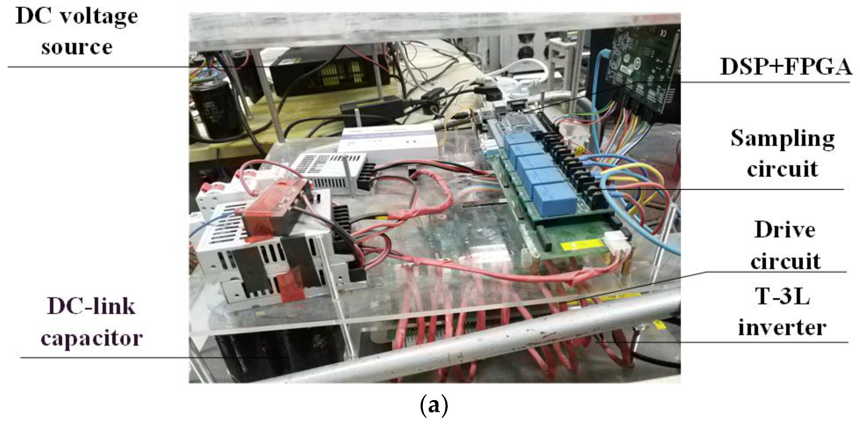
6. Simulation and Experimental Verification

Both simulation and experimental results are presented to verify the validity of open-end T-inverter fed DSPM drive system. The simulation model was built by MATLAB/Simulink, and the system parameters are given in Table 4. In the simulation, the bands of current error were set as BW1 = 0.1 V and BW2 = 0.03 V. The no-load PM flux distribution is given in Figure 2.
Figure 8 shows photograph of experimental test-bed. Figure 8a shows the control circuit. The six-phase T-type three-level inverter is elaborated by using Infineon T-3L leg F3L75R12W1H3. DSP TMS-F28335 is used to implement control algorithm and the FPGA (Xinlix-Spartan6) is used to implement the switching strategies. Figure 8b displays the DSPM and the load motor.
Figure 9 shows the simulated performance of the current hysteresis control obtained with a rotor speed of 750 rpm, a torque command of 5 Nm, and a phase-change angle α of 20°. Figure 9a shows that the torque is smoothly controlled with the control scheme. The midpoint voltage deviation in dc-link is suppressed well as shown in Figure 9b. Figure 9c displays current waveforms in phase A.
Figure 10 plots the simulated torque waveforms under traditional dual-loop control strategy and the proposed three-phase current commutation strategy. Figure 10a shows phase the torque waveforms using the traditional dual-loop control strategy, while Figure 10b shows the simulated performance using the proposed control when the phase-change angle α is 20° and Figure 10c shows the simulated performance using the proposed control when the phase-change angle α is 6.5°. The operating speed is 500 rpm and the load torque is 3 Nm for these conditions. Comparing the simulation results, it can be observed that the torque ripple is lower with the proposed three-phase current commutation strategy. Due to the low current rate of change and the low current amplitude in open-end drive, the torque ripple suppression effect is similar in Figure 10b,c.
Figure 11 shows the effect of the control of mid-point voltage in DC link. Starting the dynamo without neutral voltage control, the voltage of the upper DC capacitor Cup turns to zero. When the neutral voltage control is implemented, the voltage of the upper DC capacitor Cup rises to Vdc/2, fluctuating within a small range around Vdc/2, which proves that neutral voltage can be effectively controlled under the proposed control strategy. Figure 12 shows the comparison results between the conventional commutation strategy and the proposed commutation strategy under 600 rpm and 2 Nm load. As analyzed in Section 4, the current tracking performance is not effective with the conventional commutation strategy in Figure 12a due to different inductance values and voltages in the outgoing phase and the coming phase. The torque ripple around 2 Nm is produced. On the other hand, the current tracking is more effective since currents in three phases are under control with the proposed commutation strategy. The torque ripple is reduced to the value less than 1.6 Nm in Figure 12b.
Figure 13 displays current waveforms in phase A and switching status using proposed control in speed of 500 and 750 rpm. In addition, the phase-change angle α is 6.5°. Figure 13a,b shows the working status at a speed of 500 rpm, while Figure 13c,d shows the working status at a speed of 750 rpm. It can be seen that the current in phase A increases from 0 to iref in region α as |e(i)| > BW1, inverter switching status switches between (4, 2) and (2, 4). When |e(i)| < BW2 and the phase-change is completed, only two phase is conducted, working at switching status (4, 3), (3, 2), (3, 4), and (2, 3).
Figure 14 shows the dynamic response of speed waveform, torque response, and dc-link midpoint voltage deviation in the phase-change angle α of 6.5°. The speed changes between 500 and 750 rpm, and the torque limitation is 4 Nm. The given speed n* and the real speed n as well as the given torque T* and the real torque T are shown in Figure 14a. The dc-link midpoint voltage deviation is measured in Figure 14b. It is observed in Figure 14a that both speed and torque can quickly track the reference value. Figure 14b illustrates that neutral voltage can be well controlled in dynamic processes.

7. Conclusions

In this paper, the torque ripple mitigation and current hysteresis control strategy for a T-type three-level inverter fed open-end DSPM drive system were presented. A phase-change angle α was added during phase commutation process to suppress the torque ripple. By making one of the phase currents follow a slope rate to decrease and the other phase current follow the same slope rate to increase, the communication torque ripple can be mitigated.
To reduce the current harmonics, a multi-loop hysteresis current controller was proposed. By choosing proper switching states according to the value of current error e(i), the system performed well in tracking current and reducing the torque ripple caused by current harmonics. Meanwhile, a neutral voltage control strategy was proposed after analyzing different current loops’ impacts on mid-point voltage.
Both simulation and experimental results were given to verify validity of the proposed control scheme. It was verified that torque ripple was suppressed effectively, and phase currents were controlled well by the proposed multi-loop hysteresis current control strategy.

Author Contributions

This paper was a collaborative effort among all authors. All authors conceived the methodology, conducted the experiments, and wrote the paper.

Funding

This work is supported by the development of ultra-high electric fracturing equipment national science and technology specific projects of the twelfth five-year plan (2016ZX05038-002).

Conflicts of Interest

The authors declare no conflict of interest.

References

  1. Afinowi, I.A.A.; Zhu, Z.Q.; Guan, Y.; Mipo, J.C.; Farah, P. Hybrid-Excited Doubly Salient Synchronous Machine with Permanent Magnets Between Adjacent Salient Stator Poles. IEEE Trans. Magn. 2015, 51, 1–9. [Google Scholar] [CrossRef]
  2. Chan, B.C.C. The State of the Art of Electric, Hybrid, and Fuel Cell Vehicles. Proc. IEEE 2007, 95, 704–718. [Google Scholar] [CrossRef]
  3. Cheng, M.; Hua, W.; Zhang, J.; Zhao, W. Overview of Stator-Permanent Magnet Brushless Machines. IEEE Trans. Ind. Electron. 2011, 58, 5087–5101. [Google Scholar] [CrossRef]
  4. Cheng, M.; Chau, K.T.; Chan, C.C.; Sun, Q. Control and operation of a new 8/6-pole doubly salient permanent-magnet motor drive. IEEE Trans. Ind. Appl. 2003, 39, 1363–1371. [Google Scholar] [CrossRef]
  5. Yuan, X.; Gao, Y.; Ehsani, M. Harmonic control of chopping frequency and shaft speed in SRM. In Proceedings of the 2008 IEEE Vehicle Power and Propulsion Conference, Harbin, China, 3–5 September 2008; pp. 1–5. [Google Scholar]
  6. Lu, J.X.; Ebihara, D.; Hamatsu, K.; Arima, H. A movable angle control strategy of switched reluctance motor with Hall-effect position sensor. In Proceedings of the IPEMC 2000 Third International Power Electronics and Motion Control Conference (IEEE Cat. No.00EX435), Beijing, China, 15–18 August 2000; Volume 3, pp. 1279–1284. [Google Scholar]
  7. Harkati, N.; Moreau, L.; Zaïm, M.E.; Charpentier, J.F. Torque-speed characteristic determination of an excited doubly salient machine (DSPM). In Proceedings of the 2014 International Conference on Electrical Sciences and Technologies in Maghreb (CISTEM), Tunis, Tunisia, 3–6 November 2014; pp. 1–6. [Google Scholar]
  8. Fan, H.; Chau, K.T.; Cao, L.; Jiang, C. Design and Analysis of a New Bipolar-Flux DSPM Linear Machine. IEEE Trans. Energy Convers. 2018, 33, 2081–2090. [Google Scholar] [CrossRef]
  9. Ji, Y.; Yang, Y.; Zhou, J.; Ding, H.; Guo, X.; Padmanaban, S. Control Strategies of Mitigating Dead-time Effect on Power Converters: An Overview. Electronics 2019, 8, 196. [Google Scholar] [CrossRef]
  10. Yu, C.; Chau, K.T. Dual-Mode Operation in DC-Excited Memory Motors Under Flux Regulation. IEEE Trans. Ind. Appl. 2011, 47, 2031–2041. [Google Scholar] [CrossRef]
  11. Sekhar, K.R.; Srinivas, S. Discontinuous Decoupled PWMs for Reduced Current Ripple in a Dual Two-Level Inverter Fed Open-End Winding Induction Motor Drive. IEEE Trans. Power Electron. 2013, 28, 2493–2502. [Google Scholar] [CrossRef]
  12. Gaeta, G.; Scelba, G.; Consoli, A. Modeling and Control of Three-Phase PMSMs Under Open-Phase Fault. IEEE Trans. Ind. Appl. 2013, 49, 74–83. [Google Scholar] [CrossRef]
  13. Yi, L.; Zhao, M. Doubly Salient Permanent Magnet Motor Development Review. In Proceedings of the 2013 Third International Conference on Instrumentation, Measurement, Computer, Communication and Control, Shenyang, China, 21–23 September 2013; pp. 1513–1516. [Google Scholar]
  14. Babu, A.S.; Rajagopal, K.R.E. Analysis of multiphase doubly salient permanent magnet motors. IEEE Trans. Magn. 2005, 41, 3955–3957. [Google Scholar] [CrossRef]
  15. Hua, W.; Ming, C. Inductance characteristics of 3-phase flux-switching permanent magnet machine with doubly-salient structure. In Proceedings of the 2006 CES/IEEE 5th International Power Electronics and Motion Control Conference, Shanghai, China, 14–16 August 2006; pp. 1–5. [Google Scholar]
  16. Guo, X.; Yang, Y.; He, R.; Wang, B.; Blaabjerg, F. Transformerless Z-source four-leg PV inverter with leakage current reduction. IEEE Trans. Power Electron. 2019, 34, 4343–4352. [Google Scholar] [CrossRef]
  17. Rodriguez, J.; Franquelo, L.G.; Kouro, S.; Leon, J.I.; Portillo, R.C.; Prats, M.A.M.; Perez, M.A. Multilevel converters: An enabling technology for high-power applications. Proc. IEEE 2009, 97, 1786–1817. [Google Scholar] [CrossRef]
  18. Guo, X.; Zhou, J.; He, R.; Jia, X.; Rojas, C.A. Leakage current attenuation of a three-phase cascaded inverter for transformerless grid-connected PV systems. IEEE Trans. Ind. Electron. 2018, 65, 676–686. [Google Scholar] [CrossRef]
  19. Lezana, P.; Pou, J.; Meynard, T.A.; Rodriguez, J.; Ceballos, S.; Richardeau, F. Survey on fault operation on multilevel inverters. IEEE Trans. Ind. Electron. 2010, 57, 2207–2218. [Google Scholar] [CrossRef]
  20. Guo, X.; Jia, X. Hardware-based cascaded topology and modulation strategy with leakage current reduction for transformerless PV systems. IEEE Trans. Ind. Electron. 2016, 62, 7823–7832. [Google Scholar] [CrossRef]
  21. Wang, Z.; Wang, Y.; Chen, J.; Cheng, M. Fault-Tolerant Control of NPC Three-Level Inverters-Fed Double-Stator-Winding PMSM Drives Based on Vector Space Decomposition. IEEE Trans. Ind. Electron. 2017, 64, 8446–8458. [Google Scholar] [CrossRef]
  22. Wang, Z.; Wang, X.; Cao, J.; Cheng, M.; Hu, Y. Direct Torque Control of T-NPC Inverters-Fed Double-Stator-Winding PMSM Drives with SVM. IEEE Trans. Power Electron. 2018, 33, 1541–1553. [Google Scholar] [CrossRef]
  23. Wang, Z.; Wang, Y.; Chen, J.; Hu, Y. Decoupled Vector Space Decomposition Based Space Vector Modulation for Dual Three-Phase Three-Level Motor Drives. IEEE Trans. Power Electron. 2018, 33, 10683–10697. [Google Scholar] [CrossRef]
  24. Choi, U.; Blaabjerg, F. A novel active T-type three-level converter with open-circuit fault-tolerant control. In Proceedings of the 2015 IEEE Energy Conversion Congress and Exposition (ECCE), Montreal, QC, Canada, 20–24 September 2015; pp. 4765–4772. [Google Scholar]
Figure 1. Structure of DSPM and proposed drive system. (a) 3D Views of DSPM. (b) System configuration.
Energies 12 03109 g001
Figure 2. PM flux.
Figure 2. PM flux.
Energies 12 03109 g002
Figure 3. Back electromagnetic force (EMF) waveform.
Energies 12 03109 g003
Figure 4. The commutation from phase A to phase C.
Energies 12 03109 g004
Figure 5. Phase currents during commutation. (a) |dia/dt| > |dic/dt|. (b) |dia/dt| < |dic/dt|.
Energies 12 03109 g005
Figure 6. Phase commutation process with simultaneous three-phase conduction.
Energies 12 03109 g006
Figure 7. Current loop in different current loop. (a) (SA, Sa) = (4,2); (b) (SA, Sa) = (4,3); (c) (SA, Sa) = (3,2); (d) (SA, Sa) = (3,4); (e) (SA, Sa) = (2,3); (f) (SA, Sa) = (2,4).
Energies 12 03109 g007aEnergies 12 03109 g007b
Figure 8. Photograph of experimental test-bed. (a) Control circuit; (b) DSPM and load motor.
Energies 12 03109 g008aEnergies 12 03109 g008b
Figure 9. Simulated performance of current hysteresis control: (a) torque; (b) midpoint voltage deviation; (c) phase A current.
Energies 12 03109 g009
Figure 10. Simulated torque waveforms under different control strategy in speed of 500 rpm and load torque of 3 Nm: (a) traditional control strategy; (b) proposed three-phase current commutation strategy in phase-change angle α of 20°; (c) proposed three-phase current commutation strategy in phase-change angle α of 6.5°.
Energies 12 03109 g010
Figure 11. Measured performance of neutral voltage control.
Energies 12 03109 g011
Figure 12. Experimental results for comparison: (a) conventional commutation strategy; (b) proposed commutation strategy.
Energies 12 03109 g012
Figure 13. Experimental results of the drive in speed of 500 and 750 rpm: (a) phase current in phase-change angle α of 6.5°; (b) switching status in phase-change angle α of 6.5°; (c) phase current in phase-change angle α of 20°; (d) switching status in phase-change angle α of 20°.
Energies 12 03109 g013aEnergies 12 03109 g013b
Figure 14. Dynamic response of speed waveform, torque response, and dc-link midpoint voltage deviation at the phase-change angle α of 6.5°: (a) speed/torque response; (b) speed and dc-link midpoint voltage deviation.
Energies 12 03109 g014
Table 1. T-npc Converter switching status.
Switching StatusSA1SA2SA3SA4Status Number
PONONOFFOFF4
OOFFONONOFF3
NOFFOFFONON2
XOFFOFFOFFOFF1
Table 2. Switching Status for Hysteresis Controller (Phase A).
e(i)(SA, Sa)
e(i) > BW1(4, 2)
BW2 < e(i) ≤ BW1(4, 3), (3, 2)
−BW2 ≤ e(i) ≤ BW2Maintain the last sample cycle’s switching state
−BW1 ≤ e(i) < −BW2(3, 4), (2, 3)
e(i) < −BW1(2, 4)
Table 3. Switching Status for Mid-point Voltage Balance Control (Sa, Sa).
Current DirectionuCup < Vdc/2uCup < Vdc/2
I Energies 12 03109 i001I Energies 12 03109 i002I Energies 12 03109 i001I Energies 12 03109 i002
From A to a(3, 2)(3, 4)(4, 3)(2, 3)
From a to A(2, 3)(4, 3)(3, 4)(3, 2)
Table 4. System Parameters.
ItemsValue
Pole pair number8
Rated speed1000 rpm
Rated power750 W
DC-link voltage100 V
DC capacitors400 uF
Resistor value0.21 Ω
Sampling frequency20 kHz

