Design of Magnetic Coupler for Wireless Power Transfer


College of Electrical Engineering, Qingdao University, Qingdao 266071, China
*
Author to whom correspondence should be addressed.
Energies 2019, 12(15), 3000; https://doi.org/10.3390/en12153000
Submission received: 13 July 2019
/
Revised: 31 July 2019
/
Accepted: 1 August 2019
/
Published: 3 August 2019
Abstract
:In order to improve the restraint ability of electromagnetic energy in space and improve the coupling efficiency, a magnetic coupler structure with composite magnetic shield is proposed. Firstly, the model is established by using the finite-element simulation software. Then, according to the limit of public exposure to time-varying electromagnetic fields pointed out in ICNIPR (International Commission on Non-Ionizing Radiation Protection) guidelines, the characteristics and spatial magnetic field distribution of magnetic couplers with a single shielding structure, double shielding structure, and composite shielding structure are compared and analyzed. Finally, the experimental results show that the structure of magnetic couplers with a composite magnetic shield has a good effect in strengthening magnetic field concentration and reducing the electromagnetic interference of wireless charging systems to the external environment. It also has the advantages of smaller volume, lighter weight, and lower cost, and can effectively improve the transmission efficiency and enhance the stability of wireless charging systems.
1. Introduction
Wireless power transfer (WPT) is a system that uses a high-frequency electromagnetic field to transmit energy in space. It is more convenient and safer since it does not need cables and bolts [1]. Magnetic flux leakage in WPT will not only harm the human body, but also interfere with other electronic devices. At the same time, it will reduce the coupling coefficient and the system power [2,3]. Therefore, in order to reduce the effect of magnetic flux leakage from WPT system and improve the coupling coefficient, it is very necessary to design of the magnetic coupler. The basic magnetic coupling is composed of a receiving coil and a transmitting coil. In order to improve the coupling coefficient and reduce the power loss, a ferrite core is usually added around the magnetic coupler to restrain the electromagnetic field around the magnetic coupler.
Many studies have been done to improve the coupling coefficient of WPT systems. One type of study is to add ferrite cores around the magnetic coupler and optimize it by changing the shape of ferrite cores. The authors of [4] presented a square-embedded cross-shaped ferrite core structure for DLDD (Double Layer Double D-type) coils, which could satisfy the requirements of mutual inductance design and reduces the amount of ferrite. The authors of [5] designed and compared five different magnetic-core distribution schemes for circular pads in the wireless charging systems of electric vehicles. After considering power factor and volume of the magnetic coupler, the optimal structure was obtained. The authors of [6] presented a new design method of WPT coil shielding structure based on magnetic field characteristics of helical coils. A shielding structure called enhanced fans-shape was established, and the simulation and experimental results showed that the new structure can effectively reduce the volume of the magnetic coupler. However, it did not take into account the manufacturing process and fragile properties of ferrite. In the work cited in [7], the expressions of equivalent magnetic circuits and coupling coefficients were deduced. A new core structure was designed and optimized for DD coil, which effectively improved the coupling coefficient. There are also many studies that have used thin metal plates to shield high-frequency electromagnetic fields. The authors of [8] studied the effect of metal shielding by changing the geometric structure of metal plate and the coupling condition of WPT and explored the application of the best shielding method of metal plate in WPT systems. There are also many other types of shielding structures for reference in this paper [9,10,11,12].
At present, the shielding of magnetic couplers is generally divided into single ferrite shield or double shield composed of a ferrite and an aluminum plate. It has many problems, such as high magnetic energy loss, unsatisfactory shielding effect, relatively low efficiency, and high cost. In this paper, based on the principle of inductively coupled wireless power transfer (ICPT) system, a magnetic coupler structure with small size, light weight, low cost, and good shielding effect is proposed. The influence of composite shielding on the magnetic field distribution around the energy transfer mechanism is calculated by finite element simulation and compared with the traditional shielding structure, which verifies the rationality of the design structure. In the experiment, it is found that the magnetic coupler structure with composite magnetic shield not only strengthens the magnetic field concentration in the energy transfer area, but also reduces the electromagnetic radiation in the nonenergy transmission area, which has higher transmission efficiency than the traditional shielding structure.
2. Shielding Structure Design of Magnetic Coupler
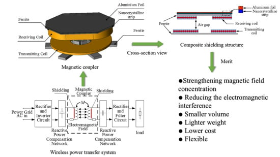
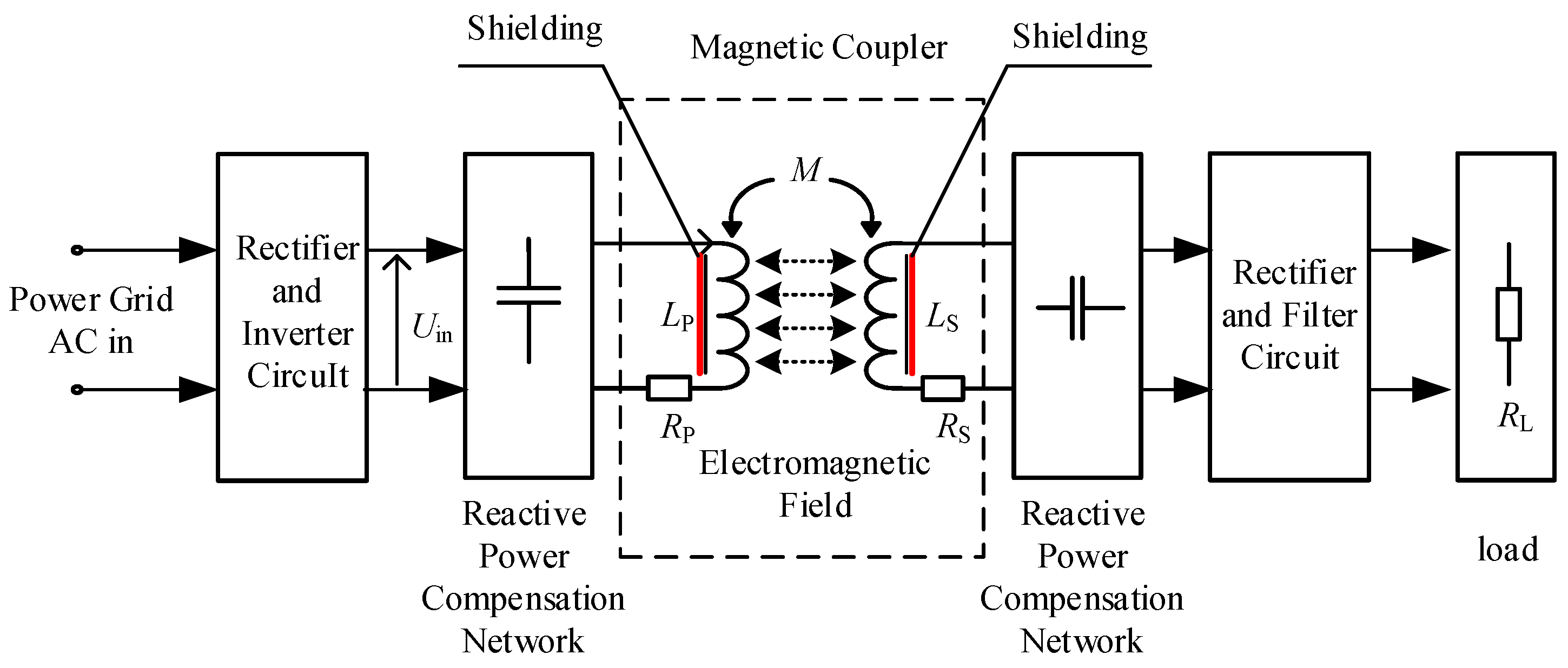
Figure 1 is the schematic diagram of the inductively coupled wireless power transfer system. When the system is working, the power frequency alternating current (AC) of the power grid is converted to DC by rectification and filtering, and then converted to high frequency AC by high-frequency inverter. After reactive power compensation, the high-frequency alternating magnetic field is generated in the transmitting coil. The high-frequency alternating magnetic field is coupled to the receiving coil to generate induction voltage, then, though the reactive power compensation network, the DC or AC power is outputted through rectifier filter circuit or rectifier filter inverter circuit to supply for the load and realize wireless transmission of energy [13].
Parallel–series topologies are adopted in this circuit—transmitting coil and compensation network are in parallel; and the receiving coil and compensation network are in series. In Figure 1, LP and LS are the inductance of transmitting coil and receiving coil. RP and RS are the internal resistance of transmitting coil and receiving coil. Uin is the output voltage of electric energy after rectification and high-frequency inversion. M is the mutual inductance between transmitting coil and receiving coil. k is the coupling coefficient. RL is the load resistance. IL is the current of RL. IP is the current of the transmitting coil, QP and QS are the quality factor of the primary and secondary circuit. η is the efficiency of the wireless charging system. In the case of full reactive power compensation, the output power PO of the system can be expressed in Equation (1) [14,15].
According to Equations (1) and (3), it is obvious that the output power increases with the coupling coefficient, and the efficiency of the wireless charging system is also influenced by the coupling coefficient. The mutual inductance and coupling factor between the coils can be changed by changing the design of the magnetic structure of the magnetic coupler.
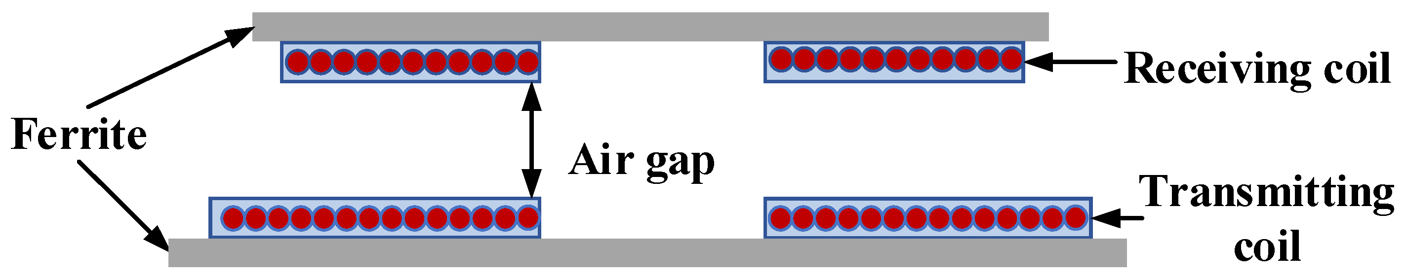
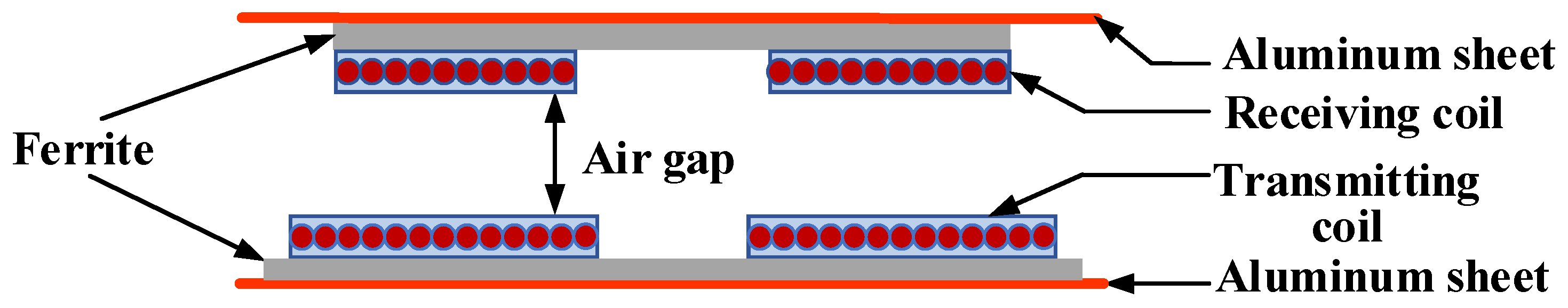
Taking the flat disk magnetic coupler as an example, the flat disk magnetic coupler can generate a uniform magnetic field in the energy transfer area. In order to reduce the magnetic field distribution in the nonworking area and enhance the magnetic field concentration in the working area, the magnetic coupler is usually designed. For magnetic couplers with shielding, the traditional ICPT shielding structure is divided into single shield and double shielding, that is, single shield composed of ferrite or double shield composed of a ferrite and an aluminum plate. The schematic diagram is shown in Figure 2 and Figure 3.
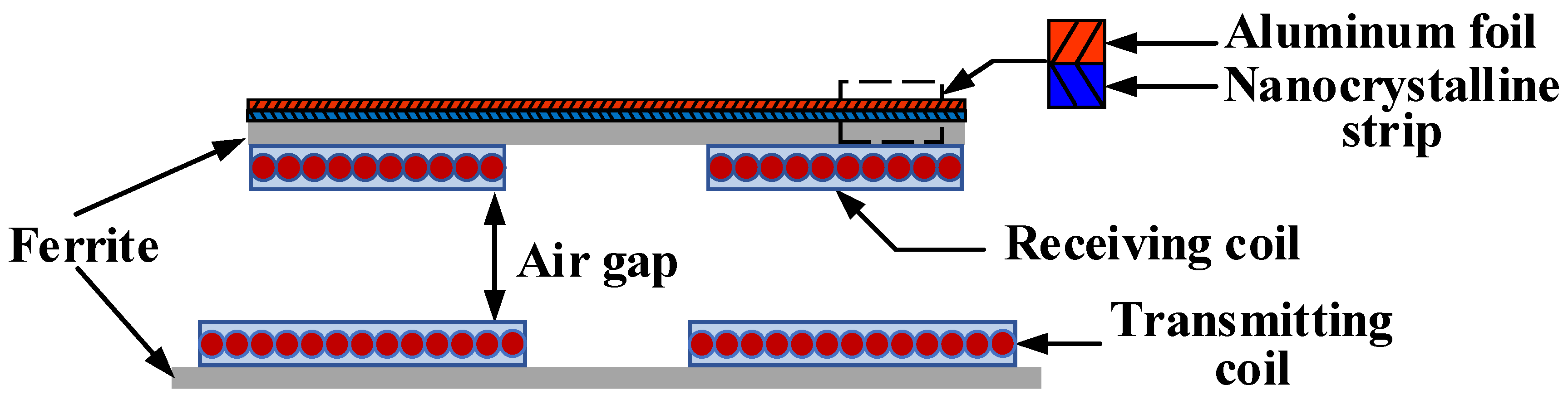
When the ferromagnetic material exists, the self-inductance L of the resonator coil increases, the resonance frequency f decreases, and the maximum transmission efficiency point of the system shifts to the left (the frequency decreases). At the same time, due to the increase of M, the maximum efficiency of the system also increases to a certain extent. At this time, if the switching frequency of the power supply at the transmitter is unchanged, the transmission efficiency will be reduced. In light-load systems, if the resonators are over-coupled, frequency splitting will occur, which will reduce the overall output power of the system. When the non-ferromagnetic aluminum plate exists, the eddy current generated in the aluminum plate produces a reverse magnetic field, which counteracts with the magnetic field of the emission source and plays a shielding role. At this time, the self-inductance L of the resonator coil decreases, the mutual inductance M of the system weakens, the resonance frequency f of the system increases, and the maximum transmission efficiency point of the system shifts to the right. For this reason, the combination of shielding materials should be considered in combination with the resonant frequency of the magnetic coupler, the switching frequency of the transmitting circuit, the transmitting frequency of the harmonic wave and the coupling coefficient. Therefore, a new type of magnetic coupler with multilayered shielding structure is proposed, as shown in Figure 4.
The first layer of the shield layer on the receiving coil side of the magnetic coupler shown in Figure 4 is a ferrite sheet, the second layer is a nanocrystalline strip, and the third layer is an aluminum foil. Ferrite is used to shield electromagnetic waves of the kHz level. The thickness of the iron-based nanocrystalline strip is only 26 μm, the resistivity is only 137 μΩ∙cm, and the saturation magnetic induction is as high as 1.6 T [16]. The aluminum foil is used for high-frequency magnetic field components that are not shielded from the first and second low-reluctance circuits. In real life, the transmitting coil is generally buried deep under the bottom or fixed, so the shielding requirement of the transmitting coil side is low, while the receiving side is usually moved. In order to save space and reduce the volume of the equipment, the receiving circuit board will be placed above the receiving coil, so the shielding requirement on the receiving side is higher.
3. Magnetic Coupler Structure
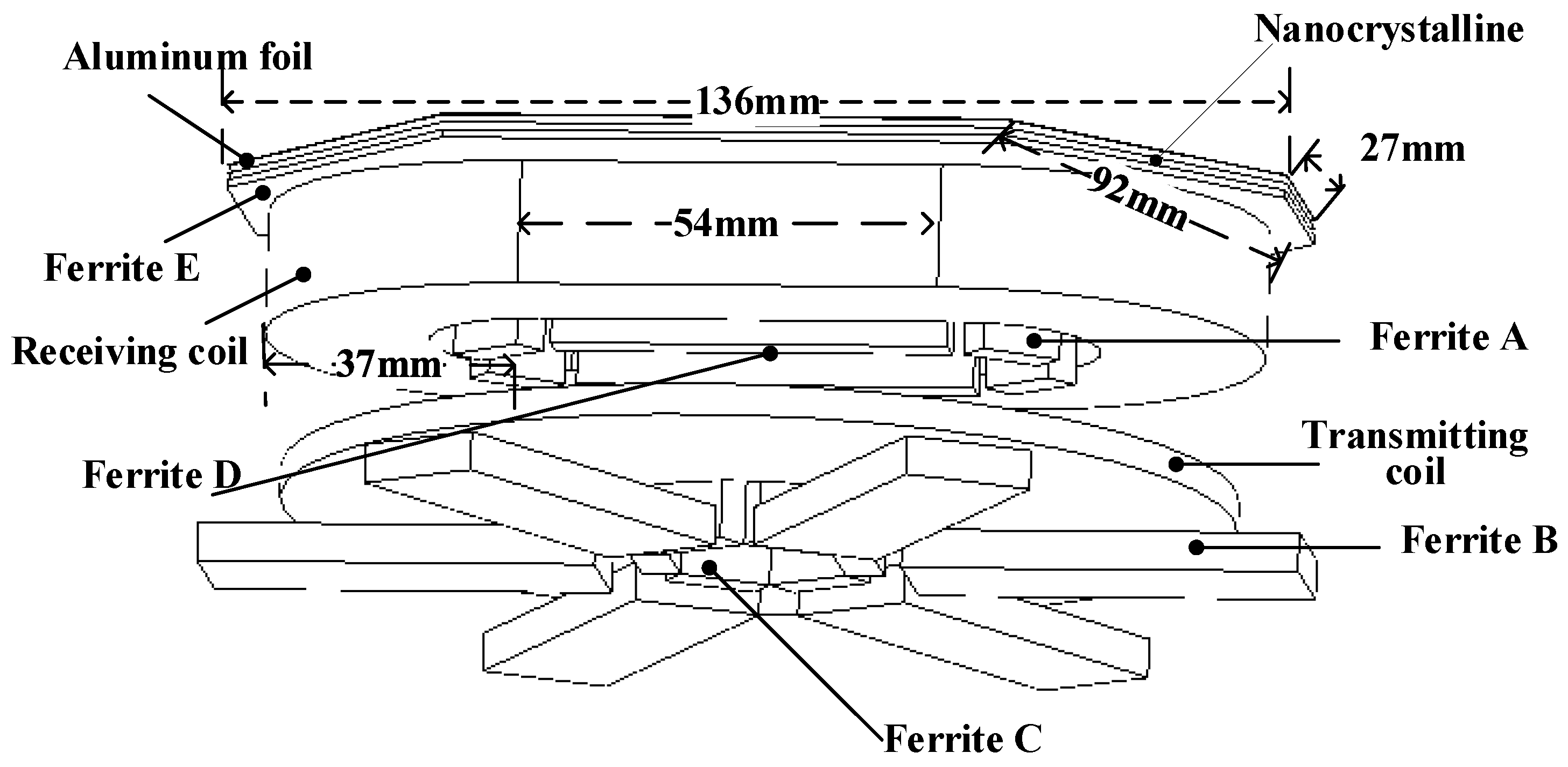
In this paper, a three-dimensional structure model of magnetic coupling for the small fruit and vegetable juicer is established. As shown in Figure 5, coil parameters are shown in Table 1; and shielding geometry parameters are shown in Table 2.
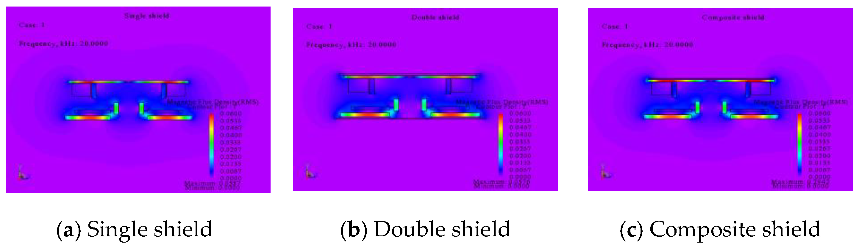
Based on the field conditions satisfied by the working area of the energy transfer mechanism, a three-dimensional finite element simulation analysis is performed to obtain a magnetic flux density distribution diagram, as shown in Figure 6. It illustrates that the double shielding structure effectively reduces the distribution of the nonworking area, while the magnetic field of the working area is also reduced. For the composite shielding structure, the magnetic field of the nonworking area above the receiving coil is lowered while the magnetic field of the working area is enhanced.
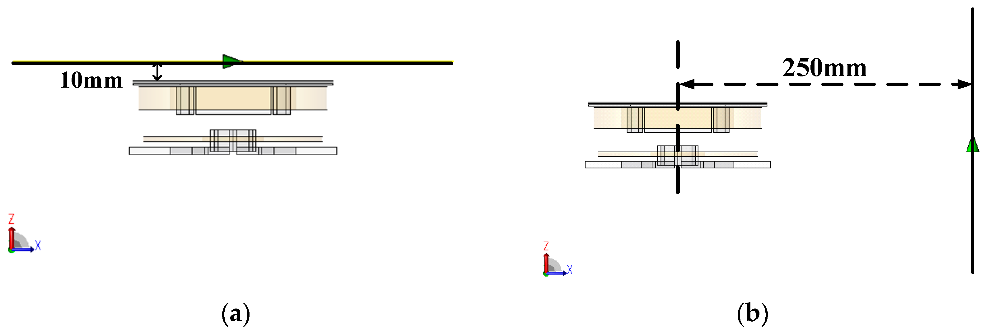
In order to suppress the influence of the electromagnetic field produced by the coil on the circuit board, it is necessary to know the radial nonworking area flux density at 10 mm above the receiving coil, and in order to suppress the radiation effect of the magnetic field on the human body, considering the packaging of the products and the user’s habits, the simulated measuring position is 250 mm from the center of the magnetic coupler to the outer axis of the magnetic coupler. The schematic diagram is shown in Figure 7.
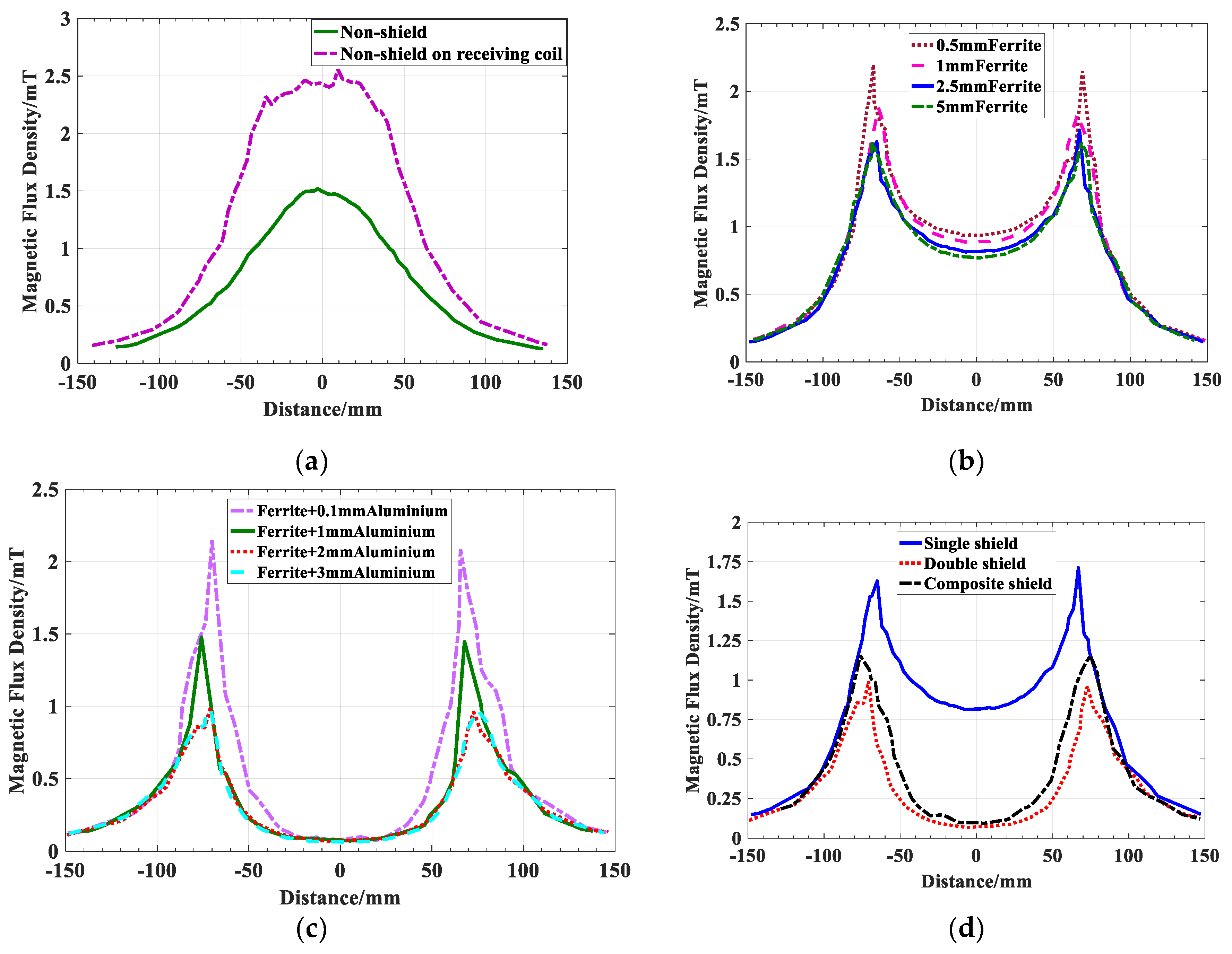
As shown in Figure 8, from −68 mm to 68 mm is the working area of magnetic coupler. When the coil is not shielded, the maximum magnetic flux density at 10 mm above the coil is 1.519 mT, the mutual inductance between the coils is 19.2 μH, and the coupling coefficient is 0.317. Due to the poor constraint on the magnetic field, the magnetic field in the nonworking area is still very strong. When ferrite is not added directly above the receiving coil, the maximum magnetic flux density at 10 mm above the coil is 2.556 mT.
When ferrite is added along the flux path, the magnetic domain of ferromagnetic material will move because of its high conductivity (relative permeability 2800 H/m) and small magnetic resistance, and the magnetic field generated by current will be applied to ferromagnetic material as an external magnetic field, which will increase the magnetic domain consistent with the magnetic field; and decrease the magnetic domain which is inconsistent with the direction of magnetic field, thus, forming a strong magnetization vector and its induced magnetic field. A large amount of flux in the air passes through ferrite, resulting in a decrease in the flux leakage in the air. Because of the high permeability of Ferrite, the flux lines in the air are attracted to the Ferrite in large quantities. Additionally, because of the existence of aluminum, the magnetic lines cannot penetrate through the aluminum plate and can only gather around the edge of the ferrite, which results in the high flux density of the edge of the magnetic coupler. The smaller the flux in the air, the better the shielding effect of the magnetic coupler.
As shown in Figure 8, as far as the single layer shielding structure is used above the receiving coil, the magnetic shielding effect using 5 mm ferrite core is best, but not much different from that of using 2.5 mm ferrite. Considering the cost, weight, and volume, the design requirements can be met by using 2.5 mm ferrite. As the ferrite thickness increases, the shielding effect increases slowly. The shielding effect of double shield is better than that of single shield, but the addition of aluminum plate will lead to the decrease of mutual inductance and coupling coefficient. The choice of aluminum plate thickness is not the thicker the better. The thinner the aluminum plate, the worse the shielding effect; and the thicker the aluminum plate, the slower the shielding effect enhancement. Table 3 shows the parameters of different types of shielding structures.
Due to the ultra-high permeability of nanocrystalline materials (relative permeability of 8000 H/m), a large amount of magnetic flux in the air is attracted by nanocrystals to the working area, which reduces the magnetic flux in the nonworking area and reduces the influence of aluminum foil on the mutual inductance of magnetic couplers.
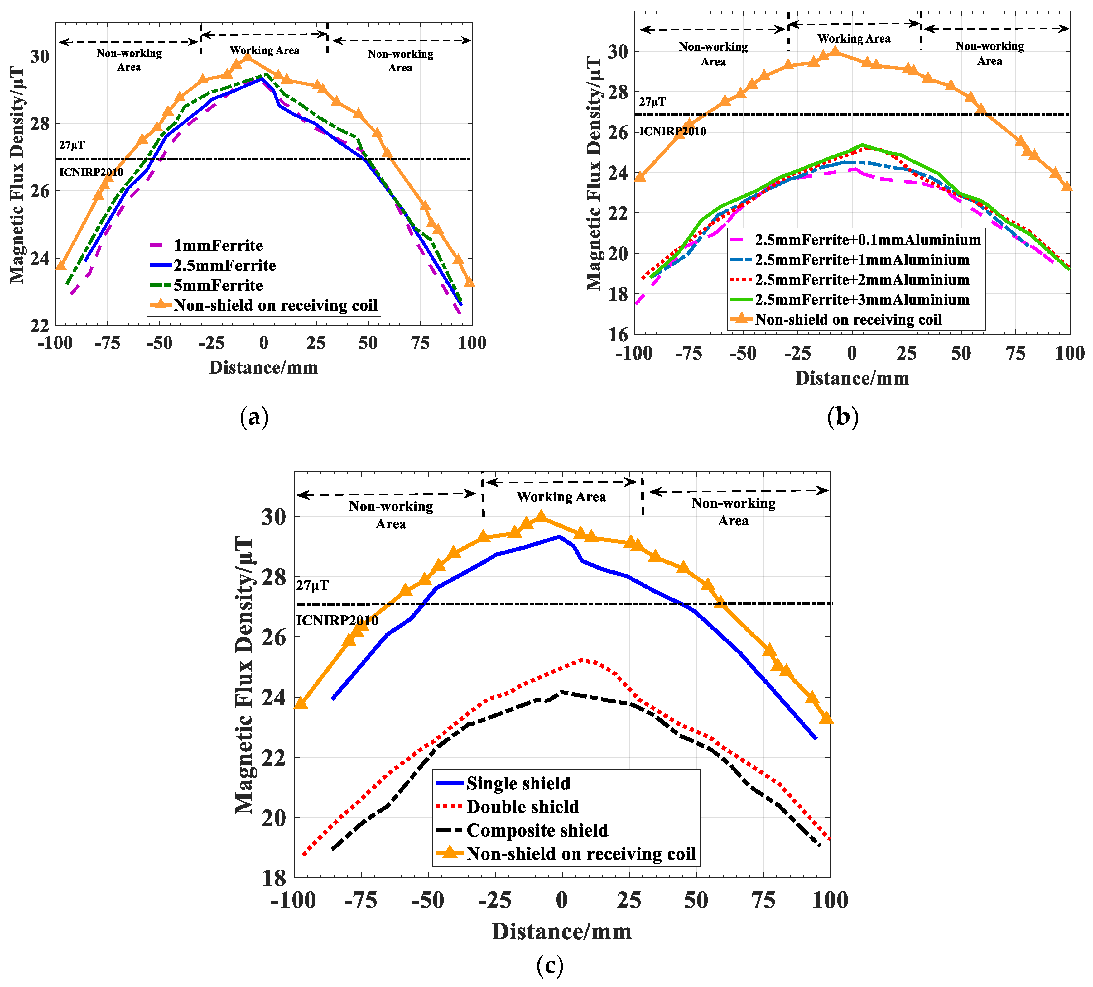
Figure 9 shows the magnetic flux density versus simulated measurement position at axial 250 mm outside the magnetic coupler. The working frequency of the magnetic coupler studied in this paper is 20 kHz, and, under this frequency, the limit value of the flux density of the public exposed to time-varying electromagnetic fields is 27 μT. From the simulation results, the thickness of magnetic couplers with single shielding structure has no obvious effect on the shielding effect, and the use of single shielding structure cannot meet the requirements of the guidelines for limited time-varying electric and magnetic field exposure issued by ICNIRP in 2010 [17]. For the magnetic couplers with double shielding structure, the thinner the aluminum plate is, the better the effect is. This is because the existence of the aluminum plate hinders the path of the magnetic flux line, which makes the magnetic flux line gather at the edge of the aluminum plate, resulting in a large flux density in air. The maximum flux density of the composite magnetic coupler in the working area is 24.2 μT, which meets the limit requirements of ICNIPR 2010.
The data in Table 4 show that the magnetic lines in space diverge in all directions without shielding, and the flux density at the measured position is small. Only after adding ferrite to the side of the transmitting coil is most of the flux in the air concentrated around the working area through the ferrite of the transmitting coil, while the receiving coil has no ferrite guiding the magnetic field, so the flux density above the magnetic coupler is high. The shielding effect of the single shielding structure is increased by 33.02% at 10 mm above the receiving coil and 2.33% at 250 mm outside the magnetic coupler. The coupling coefficient is increased by 45.11% with respect to the magnetic coupler without shielding. The shielding effect at 10 mm above the receiving coil and 250 mm outside the magnetic coupler are improved by 61.22% and 16%, respectively, by using double shielding structure, and the coupling coefficient is increased by 29.33%. The shielding effect at 10 mm above the receiving coil is increased by 54.8% and that at 250 mm outside the magnetic coupler is increased by 19.33%, and the coupling coefficient is increased by 39.11% by using the composite shielding structure. Compared with the axial shielding effect of the magnetic coupler, the shielding effect above the magnetic coupler is more obvious after using flat magnetic shielding. In terms of shielding effect, the effect of the composite shielding structure is significantly better than that of the single shielding structure. Compared with the double shielding structure, the shielding effect of the double shielding structure at the radial position 10 mm above the receiving coil is slightly better than that of the composite shielding structure, but the composite shielding effect is better in terms of the improvement of the coupling coefficient.
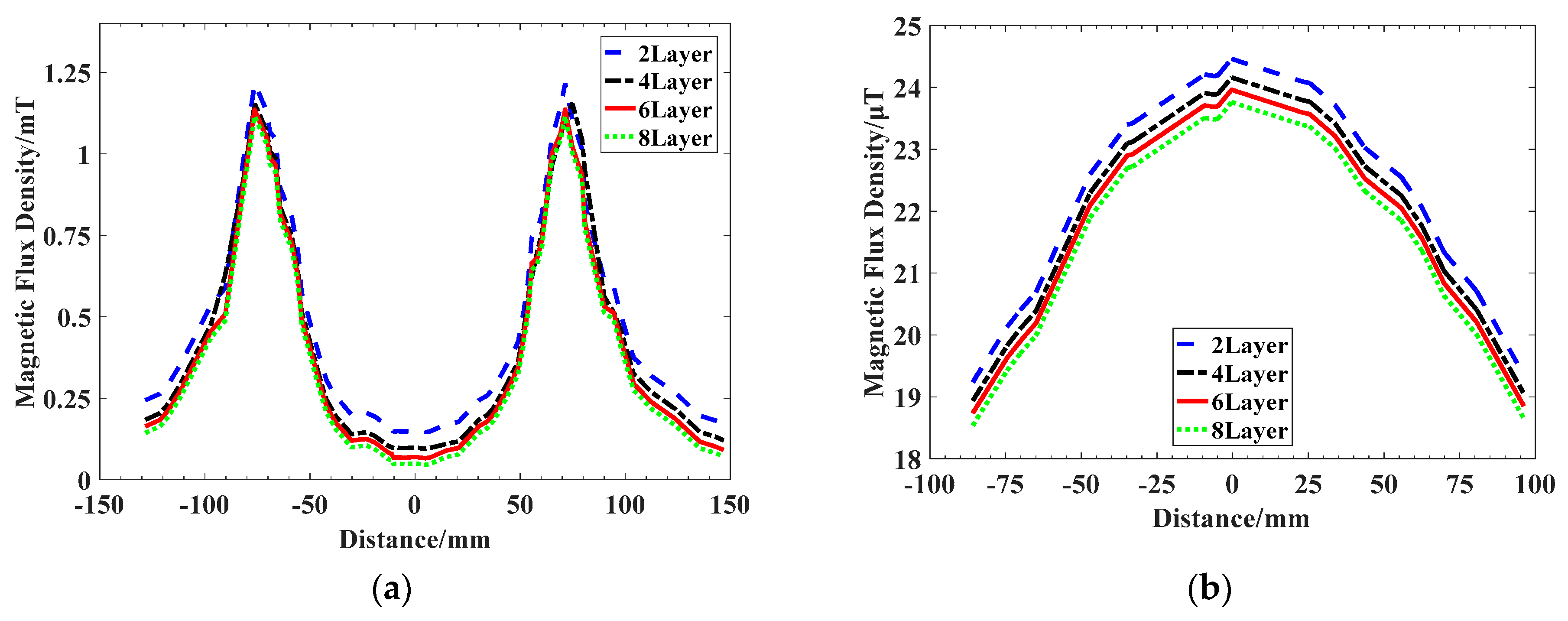
The layers of nanocrystals of the composite structure are optimized, and the magnetic coupler composed of two, four, six, and eight layers of nanocrystalline materials is modeled and simulated. Similarly, the magnetic flux density distribution at the radial direction of 10 mm above the receiving coil is obtained from the simulation results, as shown in Figure 10. The shielding effect of the composite magnetic shielding structure with two, four, six, and eight layers of nanocrystals increases by 52.46%, 54.81%, 55.56%, and 55.71%, respectively, at the radial 10 mm above the receiving coil. The shielding effect of the eight-layer nanocrystalline structure in the working area is slightly better than that of the other multilayered nanocrystalline structure, but the shielding effect at the edge of the magnetic coupler is the same as that of the four-layer nanocrystalline structure. For axial results, the number of nanocrystalline layers has little effect on the magnitude of magnetic flux density. Therefore, in order to save cost, the four layers of nanocrystalline structure should be chosen.
4. Experimental Validation
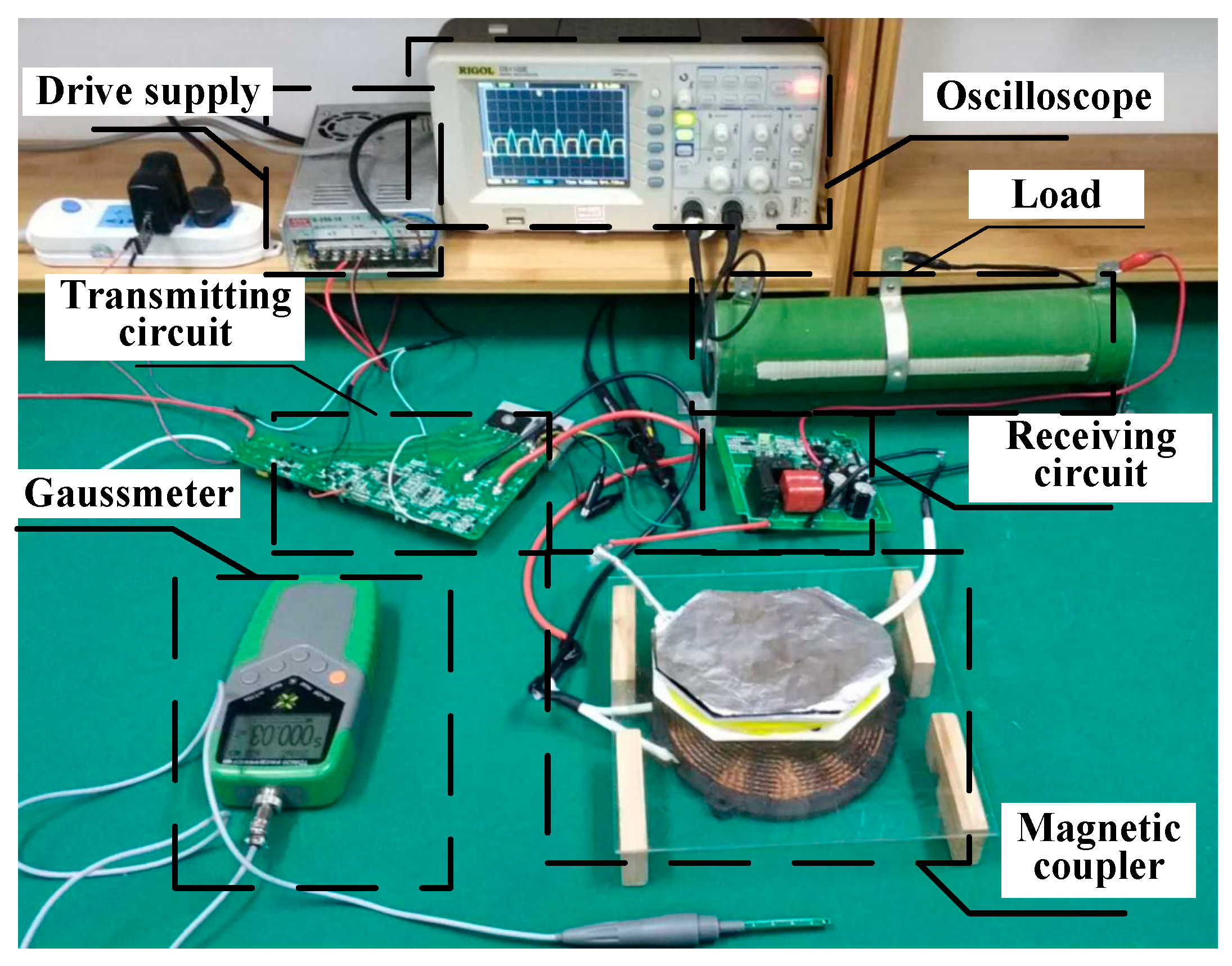
In order to verify the finite element simulation results, this paper takes the magnetic coupler of the composite shielding structure in the simulation as an example and produces the experimental model, as shown in Figure 11. Among them, the switching frequency is 20 kHz, output power is 450 W, and the load resistance is 136 Ω, which is obtained by impedance matching and is the optimal load of the magnetic coupler.
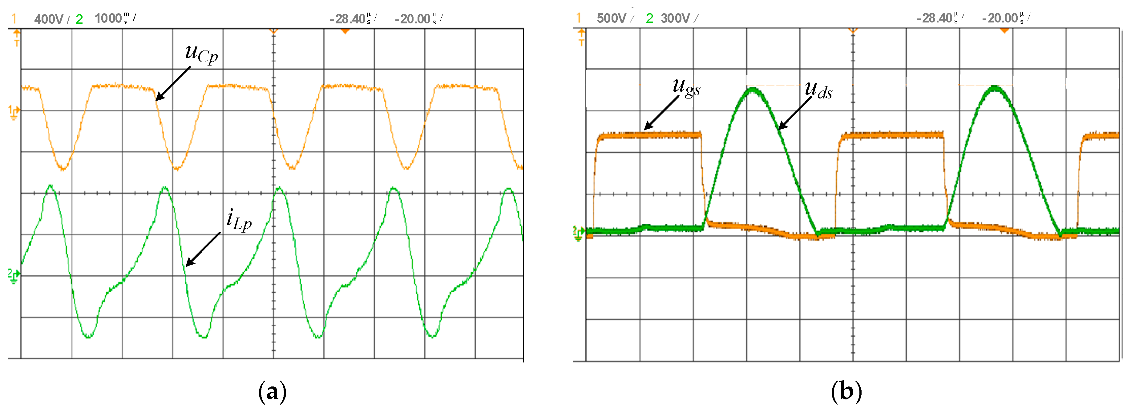
The experimental coil is wound by Litz wire, and a composite shielding layer is formed using a 1 mm thick MnZn ferrite, 4 layers of nanocrystals, and 0.1 mm thick aluminum foil for the coil to form a composite shielding magnetic coupler. As shown in Figure 12a, iLp is the current flowing through the transmitting coil and uCp is the voltage across the compensation capacitor in parallel with the transmitting circuit. In this paper, a single switching resonant converter is used. The P-S type of reactive power compensation circuit uses parallel compensation on the primary side and series compensation on the secondary side. As the equivalent input power supply on the primary side is not a pure sinusoidal, the shape of the primary side current is not a sinusoidal wave too. As shown in Figure 12b, ugs is the switching transistor driving voltage, and uds is the voltage between the drain and the source. Before the switch control signal ugs comes, the voltage uds between the drain and source of the switch has been reduced to zero, achieving zero voltage turn-on and reducing switching losses. At the resonant frequency, the approximate value of the (DC-DC) efficiency of the whole system is obtained by using the oscilloscope to measure and calculate the voltage and current on the original rectifier module and the load. The efficiency of the WPT system with single shielding magnetic couplers is 79%, the efficiency of the WPT system with double shielding magnetic couplers is 68%, and the efficiency of the WPT system with composite shielding magnetic couplers is 87%. Therefore, the composite structure magnetic couplers can effectively improve the efficiency of the magnetic couplers under the circuit parameters.
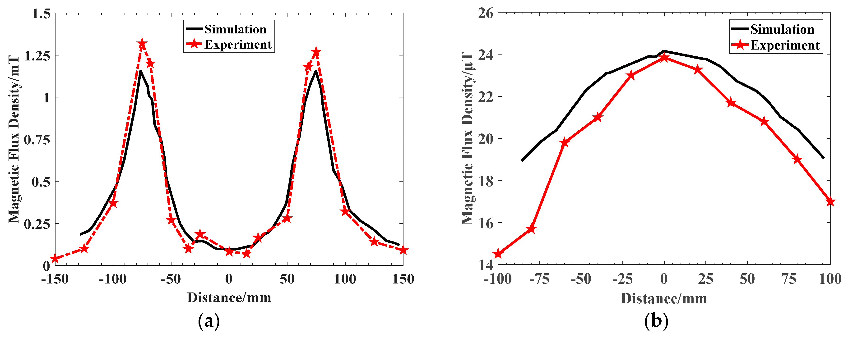
As shown in the Figure 13, the 10 mm radial flux density curve above the coil and the 250 mm axial flux density curve of the magnetic coupler are received. Due to the influence of the experimental environment, there is a slight error between the test results and the simulation results.
5. Conclusions
In this paper, the finite element analysis of the magnetic coupling mechanism of the wireless power transfer system is carried out, and the magnetic flux density distribution of the magnetic coupler is obtained. The magnetic shielding of the composite shielding structure and the traditional single shielding structure and double shielding structure are compared and analyzed. The results show that the maximum radial nonworking area flux density at 10 mm above the receiving coil decreases from the original 2.556 mT to 1.155 mT, the axial nonworking area maximum flux density at 250 mm outside the magnetic coupler decreases from the original 30 μT to 24.2 μT, the leakage flux in the nonworking area decreases obviously, the magnetic flux in the working area is effectively constrained, the mutual inductance of the magnetic coupling mechanism increases by 2.8 times, and the coupling coefficient increases by 39.11%. The efficiency of the system is 87%. At the same time, the composite shielding structure is optimized, and the composite shielding magnetic coupler with four layers of nanocrystalline structure is selected considering the shielding effect and cost. The experimental verification is carried out. Compared with the traditional magnetic shielding structure, the composite structure magnetic couplers are only 75% of the traditional magnetic couplers, and the aluminum content is only 5% of the traditional magnetic couplers. The shielding effect is slightly better than the traditional shielding structure, it is flexible and easy to operate, and it can be used in any kind of shielding structure.
Author Contributions
Methodology, H.X. and C.W.; Software, H.X.; Validation, H.X. and Y.L.; Formal Analysis, H.X.; Investigation, H.X. and D.X.; Writing-Original Draft Preparation, H.X.; Writing-Review & Editing, C.W. and D.X..; Visualization, H.X. and Y.L.; Supervision, C.W.; Project Administration, C.W.; Funding Acquisition, C.W.
Funding
This research was funded by National Natural Science Foundation of China grant number: 51877113. And The APC was funded by National Natural Science Foundation of China.
Conflicts of Interest
The authors declare no conflicts of interest.
References
- Wang, C.S.; Covic, G.A.; Stielau, O. Investigating an LCL load resonant inverter for inductive power transfer applications. IEEE Trans. Power Electron. 2004, 19, 995–1002. [Google Scholar] [CrossRef]
- Ding, P.P.; Bernard, L.; Pichon, L.; Razek, A. evaluation of electromagnetic fields in human body exposed to wireless inductive charging system. IEEE Trans. Magn. 2014, 50, 1037–1040. [Google Scholar] [CrossRef]
- Jobava, R.G.; Gheonjian, A.L.; Hippeli, J.; Chiqovani, G.; Karkashadze, D.D.; Bogdanov, F.G.; Khvitia, B.; Bzhalava, A.G. Simulation of low-frequency magnetic fields in automotive EMC problems. IEEE Trans. Electromagn. Compat. 2014, 56, 1420–1430. [Google Scholar] [CrossRef]
- Li, Z.; Song, K.; Wei, G.; Jiang, J.H.; Zhu, C.B. A 3 kW wireless power transfer system for sightseeing car supercapacitor charge. IEEE Trans. Power Electron. 2016, 32, 3301–3316. [Google Scholar] [CrossRef]
- Budhia, M.; Covic, G.A.; Boys, J.T. Design and optimization of circular magnetic structures for lumped inductive power transfer systems. IEEE Trans. Power Electron. 2011, 26, 3096–3108. [Google Scholar] [CrossRef]
- Dai, Z.; Wang, J.; Long, M.; Huang, H.; Sun, M. Magnetic shielding structure optimization design for wireless power transmission coil. AIP Adv. 2017, 7, 095013. [Google Scholar] [CrossRef]
- Wen, F.; Huang, X. Optimal magnetic field shielding method by metallic sheets in wireless power transfer system. Energies 2016, 9, 733. [Google Scholar] [CrossRef]
- Tan, L.; Li, J.; Chen, C.; Yan, C.; Guo, J.; Huang, X. Analysis and performance improvement of WPT systems in the environment of single non-ferromagnetic metal plates. Energies 2016, 9, 576. [Google Scholar] [CrossRef]
- Ren, S.; Xia, C.; Liu, L.; Wu, X.; Yu, Q. Cross-shaped magnetic coupling structure for electric vehicle IPT charging systems. J. Power Electron. 2018, 18, 1278–1292. [Google Scholar]
- Elnail, K.E.I.; Huang, X.L.; Xiao, C.; Tan, L.L.; Xu, H.Z. Core structure and electromagnetic field evaluation in WPT systems for charging electric vehicles. Energies 2018, 11, 1734. [Google Scholar] [CrossRef]
- Yao, Y.; Wang, Y.J.; Liu, X.S.; Pei, Y.; Xu, D.G. A novel unsymmetrical coupling structure based on concentrated magnetic flux for high-misalignment IPT applications. IEEE Trans. Power Electron. 2018, 34, 3110–3123. [Google Scholar] [CrossRef]
- Budhia, M.; Boys, J.T.; Covic, G.A.; Huang, C.Y. Development of a single-sided flux magnetic coupler for electric vehicle IPT charging systems. IEEE Trans. Ind. Electron. 2013, 60, 318–328. [Google Scholar] [CrossRef]
- Zhang, X.; Zhang, P.; Yang, Q.; Yuan, Z.; Su, H. Magnetic shielding design and analysis for wireless charging coupler of electric vehicles based on finite element method. Trans. China Electrotech. Soc. 2016, 31, 71–79. [Google Scholar] [CrossRef]
- Boys, J.T.; Covic, G.A.; Green, A.W. Stability and control of inductively coupled power transfer systems. IEE Proc. Electr. Power Appl. 2000, 147, 37–43. [Google Scholar] [CrossRef]
- Lin, F.Y.; Covic, G.A.; Boys, J.T. Evaluation of magnetic pad sizes and topologies for electric vehicle charging. IEEE Trans. Power Electron. 2015, 30, 6391–6407. [Google Scholar] [CrossRef]
- Muhlethaler, J.; Biela, J.; Kolar, J.W.; Ecklebe, A. Core losses under the DC bias condition based on steinmetz parameters. IEEE Trans. Power Electron. 2012, 27, 953–963. [Google Scholar] [CrossRef]
- Mcrobbie, D. Guidelines for limiting exposure to time-varying electric and magnetic fields (l Hz to 100 kHz). Health Phys. 2010, 99, 818–836. [Google Scholar]
Figure 1.
The schematic diagram of the inductively coupled wireless power transfer (WPT) system.

Figure 2.
Cross-section view of single shield magnetic coupler.

Figure 3.
Cross-section view of double shield magnetic coupler of WPT system.

Figure 4.
Cross-section view of composite shield magnetic coupler of WPT system.

Figure 5.
A 3D structure model of magnetic coupling for the small fruit and vegetable juicer.

Figure 6.
Simulated magnetic flux density distribution in a cross-section of different types of magnetic coupler.
Figure 6.
Simulated magnetic flux density distribution in a cross-section of different types of magnetic coupler.

Figure 7.
Schematic diagram of simulated measurement position. (a) Radial position 10 mm above the receiving coil. (b) Axial position 250 mm outside the magnetic coupler.
Figure 7.
Schematic diagram of simulated measurement position. (a) Radial position 10 mm above the receiving coil. (b) Axial position 250 mm outside the magnetic coupler.

Figure 8.
Magnetic flux density versus simulated measurement position at radial 10 mm above receiving coil. (a) No shielding. (b) Single shield magnetic coupler with different ferrite thickness. (c) Double shield magnetic coupler with different aluminum thickness. (d) Comparison of different shielding types.

Figure 9.
Magnetic flux density versus simulated measurement position at axial 250 mm outside the magnetic coupler. (a) Single shield magnetic coupler with different ferrite thickness. (b) Double shield magnetic coupler with different aluminum thickness. (c) Comparison of different shielding types.
Figure 9.
Magnetic flux density versus simulated measurement position at axial 250 mm outside the magnetic coupler. (a) Single shield magnetic coupler with different ferrite thickness. (b) Double shield magnetic coupler with different aluminum thickness. (c) Comparison of different shielding types.

Figure 10.
Magnetic flux density versus simulated measurement position. (a) Radial 10 mm above receiving coil. (b) Axial 250 mm outside the magnetic coupler.
Figure 10.
Magnetic flux density versus simulated measurement position. (a) Radial 10 mm above receiving coil. (b) Axial 250 mm outside the magnetic coupler.

Figure 11.
Experimental setup of the WPT system.

Figure 12.
Experiment results. (a) Current and voltage waveforms of transmitting circuit. (b) Drive voltage and voltage waveform between drain and source.
Figure 12.
Experiment results. (a) Current and voltage waveforms of transmitting circuit. (b) Drive voltage and voltage waveform between drain and source.

Figure 13.
Magnetic flux density versus distance of experiment and simulation comparison. (a) Radial position 10 mm above the receiving coil with composite shielding coupler on receiving coil coupler. (b) Axial 250 mm outside the magnetic coupler with composite shielding coupler on receiving coil.
Figure 13.
Magnetic flux density versus distance of experiment and simulation comparison. (a) Radial position 10 mm above the receiving coil with composite shielding coupler on receiving coil coupler. (b) Axial 250 mm outside the magnetic coupler with composite shielding coupler on receiving coil.


Table 1.
Parameter of the coil.
| Parameter | Data |
|---|---|
| Outer-diameter of transmitting coil | 122 mm |
| Inner-diameter of transmitting coil | 42 mm |
| Outer-diameter of receiving coil | 37 mm |
| Inner-diameter of receiving coil | 16 mm |
| Length of receiving coil | 54 mm |
| Turns of transmitting coil | 28 |
| Turns of receiving coil | 30 |
| Transmission distance | 18 mm |
Table 2.
Geometry parameters of shielding material.
| Material | Size/mm | Number |
|---|---|---|
| Ferrite A | 10*5*19 | 4 |
| Ferrite B | 51*17*5 | 6 |
| Ferrite C | 12*5*15 | 6 |
| Ferrite D | 51*5*19 | 2 |
| Ferrite E |  | 1 |
| Nanocrystalline | 1 | |
| Aluminum foil | 1 |
Table 3.
Parameters of different types of shielding structure for receiving coil.
| Magnetic Coupler | Parameter | Value |
|---|---|---|
| single shield magnetic coupler | ferrite thickness | 2.5 mm |
| double shield magnetic coupler | ferrite thickness | 2.5 mm |
| aluminum plate thickness | 2 mm | |
| composite shield magnetic coupler | ferrite thickness | 1 mm |
| nanocrystalline strips | 26 μm | |
| aluminum foil thickness | 0.1 mm |
Table 4.
Data of different magnetic coupling structures.
| Shielding Type | The Maximum Radial Flux Density of 10 mm above the Receiving Coil/mT | Maximum Axial Flux Density of Magnetic Couplers in 250 mm/μT | Mutual Inductance/μH | Coupling Coefficient |
|---|---|---|---|---|
| Magnetic coupler without shielding | 1.519 | 27.4 | 19.2 | 0.317 |
| Non-shield on receiving coil | 2.556 | 30 | 37.5 | 0.408 |
| Single shield | 1.712 | 29.3 | 57.1 | 0.460 |
| Double shield | 0.991 | 25.2 | 46.8 | 0.410 |
| Composite shield | 1.155 | 24.2 | 53.9 | 0.441 |
© 2019 by the authors. Licensee MDPI, Basel, Switzerland. This article is an open access article distributed under the terms and conditions of the Creative Commons Attribution (CC BY) license (http://creativecommons.org/licenses/by/4.0/).
Share and Cite
MDPI and ACS Style
Xu, H.; Wang, C.; Xia, D.; Liu, Y. Design of Magnetic Coupler for Wireless Power Transfer. Energies 2019, 12, 3000. https://doi.org/10.3390/en12153000
AMA Style
Xu H, Wang C, Xia D, Liu Y. Design of Magnetic Coupler for Wireless Power Transfer. Energies. 2019; 12(15):3000. https://doi.org/10.3390/en12153000
Chicago/Turabian StyleXu, Heqi, Chunfang Wang, Dongwei Xia, and Yunrui Liu. 2019. "Design of Magnetic Coupler for Wireless Power Transfer" Energies 12, no. 15: 3000. https://doi.org/10.3390/en12153000
Note that from the first issue of 2016, this journal uses article numbers instead of page numbers. See further details here.