Impact of Information and Communication Technology Limitations on Microgrid Operation


1
Department of Electrical Engineering, The City University of New York, City College, New York, NY 10031, USA
2
Department of Electrical and Computer Engineering, American University of Beirut, Beirut 1107 2020, Lebanon
3
Department of Electrical Engineering (on leave), Menia University, Menia 61519, Egypt
*
Author to whom correspondence should be addressed.
Energies 2019, 12(15), 2926; https://doi.org/10.3390/en12152926
Submission received: 8 May 2019
/
Revised: 26 June 2019
/
Accepted: 5 July 2019
/
Published: 30 July 2019
(This article belongs to the Special Issue Sustainable Energy Systems)
Abstract
:This paper provides an extensive review of the conducted research regarding various microgrids (MGs) control techniques and the impact of Information Communication Technology (ICT) degradation on MGs performance and control. Additionally, this paper sheds the light on the research gaps and challenges that are to be explored regarding ICT intrinsic-limitations impact on MGs operations and enhancing MGs control. Based on this assessment, it offers future prospects regarding the impact of ICT latencies on MGs and, consequently, on the smart grid. Finally, this paper introduces a case study to show the significance and examine the effect of wireless communication technologies latency on the converters and the DC bus voltage of a centralized controlled DC MG. A DC microgrid with its communication-based control scheme was modeled to achieve this goal. The MATLAB simulation results show that the latency impact may be severe on the converter switches and the DC bus voltage. Additionally, the results show that the latency impact varies depending on the design of the MG and its operational conditions before the latency occurs.
1. Introduction
The United States (U.S.) electric power grid is undergoing unprecedented changes triggered by:
- the aging of the centralized energy infrastructure, which can be more vulnerable with the increasing power demand;
- the governmental carbon pollution standards around the world to reduce carbon dioxide (CO2) emissions along with federal and state regulatory actions to reduce greenhouse gas (GHG) emissions from new and existing power plants. This encouraged the implementation of more renewable energy sources (RESs) into the electric grid [1,2], especially, since 29% of the U.S. GHG emissions are only produced from electricity generation [3]. However, RESs are intermittent by nature imposing a challenge on load forecasting and maintaining generation/demand balance; and,
- the rise in the frequency and magnitude of major events, as well as the increasing salience of threats, such as cyber and physical attacks against the grid, make it necessary to not only think about the reliability, but also about the resilience of the grid and its ability to withstand and recover from major events, and be a flexible platform for higher levels of integration of RES.
The future smart grid is envisioned to be highly resilient when compared to the legacy power grid and it is equipped to deal autonomously with high demand/generation uncertainties (e.g., withstand different levels of intermittency that might be associated with higher levels of RESs integration). Its probability to fail is minimal and, more essentially, if it were to fail due to an event, such as natural disasters or human errors, it shall be able to partially sustain the power supply and restore the service faster and more flexibly [4].
The transition from traditional power grids to smarter ones mandates increased the dependence on information and communication technologies (ICT) [5,6]. This dependence is continuously growing with the introduction and evolution of emerging technologies, such as microgrids (MGs), phasor measurement units, advanced metering infrastructure (AMI), and electric vehicles (EVs).
This paper is organized, as follows:
- Section 2 presents a literature review about smart grids and microgrids and their conceived capabilities, followed by a literature survey and the research gaps regarding MG’s types and control techniques. Finally, introduces a review of the conducted research and the research opportunities regarding the impact of ICT on MGs control and performance.
- Section 2 also discusses the communication architecture and its functional requirements (e.g., allowable delays, bandwidth ranges) for smart grids and MGs applications. Moreover, it references the available software that could be utilized to simulate communication networks, and it discusses the sources of delays in these networks.
- Section 3 introduces a DC MG model that will be used as a case study to show the impact of communication delays on MG performance.
- Section 4 shows the control layer of the aforementioned DC MG.
- Section 5 demonstrates the impact of one of the ICT’s degradation, which is the delay, on the performance of the DC MG case study.
- Finally, Section 6 introduces the conclusion of this paper.
2. Literature Survey
2.1. Smart Grid Vision
A smart grid can be defined as a modernized electrical grid that utilizes communications and information technology to make automated decisions to improve the reliability, resilience, economics, efficiency, and sustainability of the production and distribution of electricity. Their abilities to autonomously stave off the rampant repercussions of crucial faults preventing blackouts and mitigating swift changes that are associated with RESs intermittent nature is one of the main disparities between smart and legacy grids (e.g., cloud passing by solar panels). The definitive model of the smart grid has yet to be defined; however, the model will reflect the widely recognized key capabilities essential for successful implementation, such as [7]:
- enabling massive deployment and efficient usage of MGs and distributed energy resources (DERs) with integration abilities to communication-based control platforms. This mandate expanding existing standards and data models to accommodate new technologies; such efforts are seen in new revisions of the IEC 61850 standard;
- improving resilience against disruption providing stable and continuous electricity supplies, thus averting wide area accidental blackouts. In other words, smart grid shall guarantee the secure and normal operation of the grid even during emergency issues (e.g., extreme weather, natural disasters, and intentional breakage), enhances sustainability and provides self-healing capabilities;
- securing the information transmitted all over the grid; facilitating the interaction of consumers with energy management systems (EMS) to support load shaping (e.g., peak shaving) and demand-response functionalities;
- allowing for scalable real-time monitoring of grid operations and status. This effort can be seen in the deployment of advanced metering infrastructures (AMIs) and monitoring systems (e.g., phasor measurement units (PMUs));
- implementing an optimized configuration of resources and reducing grid losses; and,
From a practical point of view, the aforementioned presented vision of a smart grid requires pervasive and effective two-way communication and monitoring capabilities [10].
2.2. Microgirds
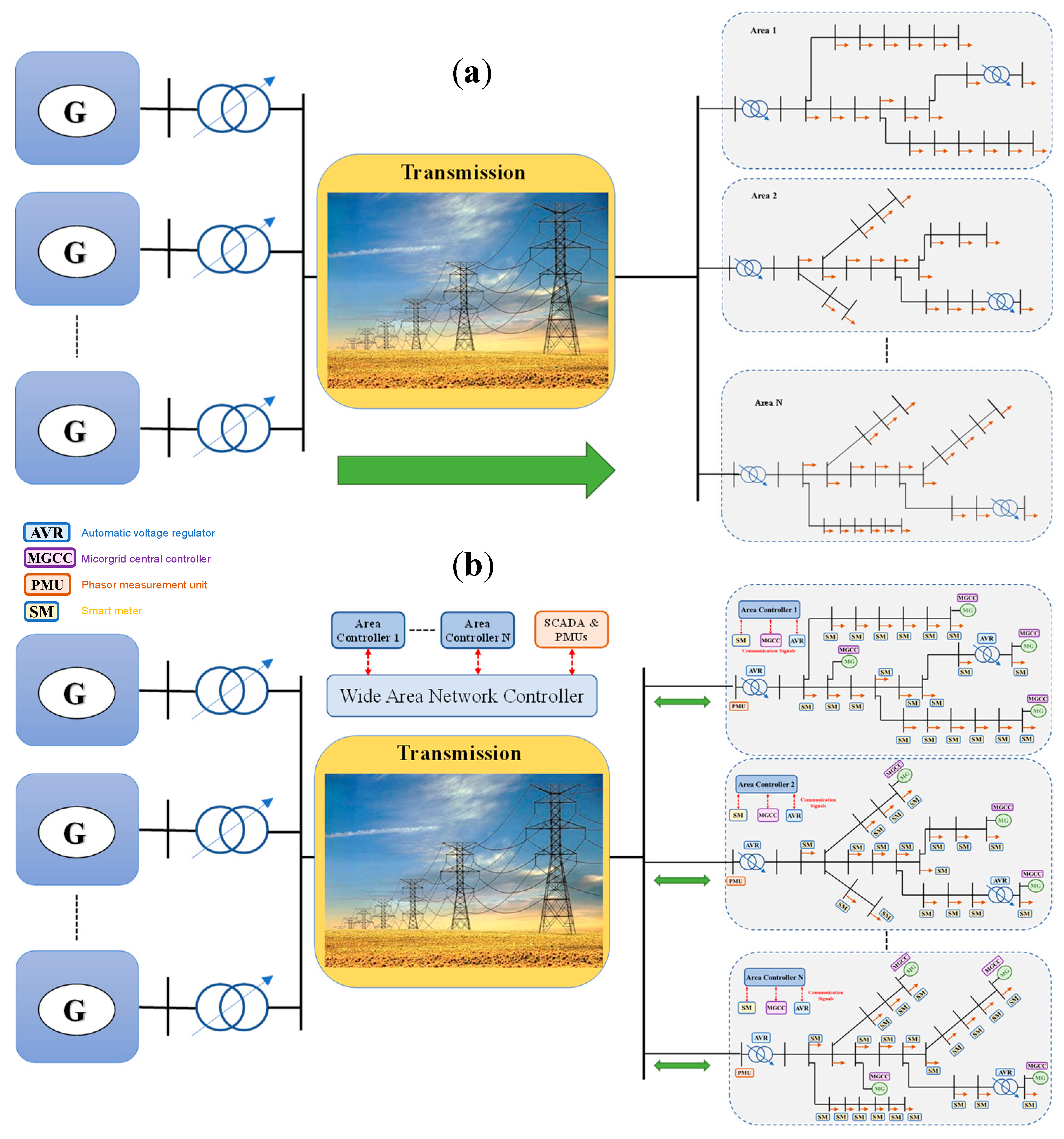
A microgrid is a key foundational building block for enabling the future smart grids. MGs and distributed energy resources (DERs) allowed for the existence of energy resources in the distribution level and enabled the flow of energy in a bidirectional manner instead of the conventional one (i.e., unidirectional), as shown in Figure 1a,b and Figure 2.
An MG can be visualized as a miniaturized power grid. It can be described—according to the definition adopted by the U.S. department of energy (DOE) and European Union (EU) agencies—as a cluster of interconnected resources (e.g., DERs), ESS and loads, which acts as an independent controllable entity with respect to the power grid. MGs are tied to the power grid through one or more nodes, namely the points of common coupling (PCC). An MG must be capable to function in either a grid-tied mode or an islanded mode depending on the grid availability, among other conditions (i.e., disconnected from the main grid) [11,12].
If microgrids are designed and operated to function only during blackouts, their deployment would not be cost effective. Besides resiliency, MGs can provide numerous services to independent system operators (ISOs) at the transmission level, utilities at the distribution level, and end customers. These services add new revenue streams during normal operation. For example:
- at the customer level, MGs can exploit time-of-use pricing to lower consumer costs through energy arbitrage, or provide needed energy/capacity to the grid;
- at the distribution level, MGs can participate in demand side management and demand response programs to help the utilities shave their peak demand, while also offering economic benefits to MGs owners. Besides, MGs can relieve congestion on transmission lines (TLs) by satisfying a portion of the loads locally, eliminating some of the high fees that utilities would normally be charged by their respective ISO/RTOs when using congested TLs (i.e., heavily loaded); and,
- at the transmission level, if large-scale or aggregated MGs can provide frequency regulation, and potentially help defer investments in generation and transmission infrastructures. MGs can also provide spin/non-spin reserve by using their backup generator (e.g., diesel engines) or installed energy storage system (ESS) (e.g., battery). Voltage support and black-start can also be provided by MGs.
These services, besides resiliency, can potentially make MGs valuable economical assets in all smart grid levels depending on the MGs’ business model. An MG is one of the main pillars in achieving resiliency at all of the smart grid levels. For example, in the case of a blackout: in the customer level, it can island itself from the grid and supply its own loads; at the distribution level, it could cluster with other MGs and form community microgrids to supply the critical loads within a distribution area.
2.3. Microgrid Types and Control Techniques
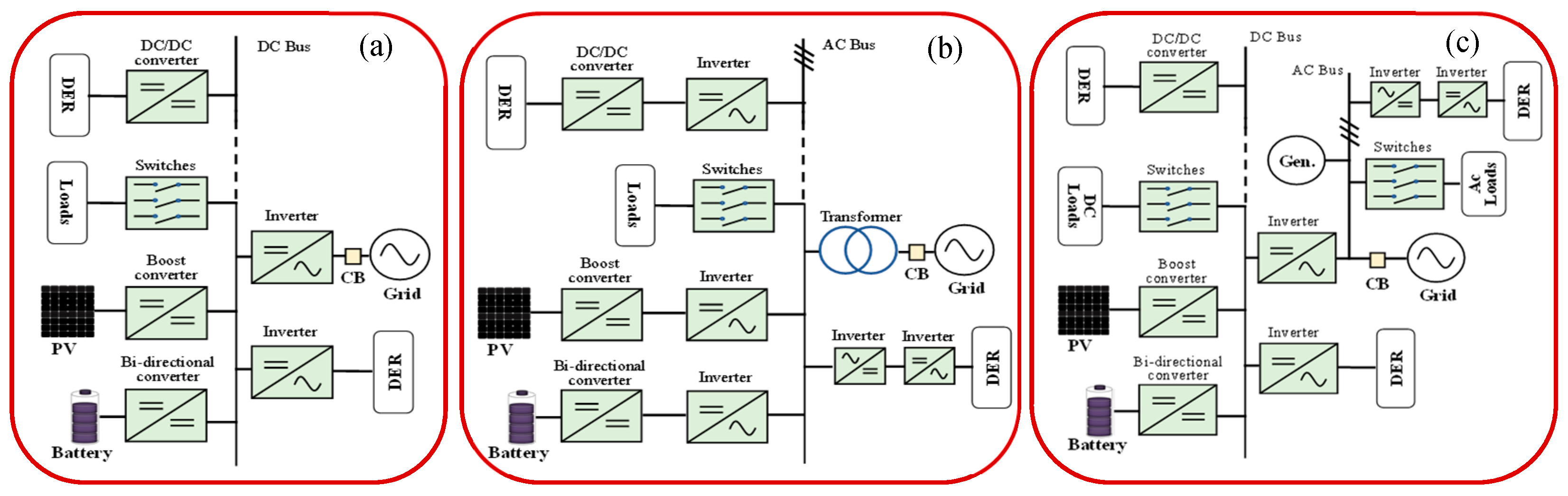
A microgrid can be classified into three main types: DC, AC, or hybrid AC/DC MG, based on the voltage of the main bus linking all of its assets. In AC MGs, all of the MG assets are tied to an AC bus either via converters or directly, whereas the main grid connects to the same common AC bus. As AC MG builds upon our knowledge of the main grid, it is easier to design and operate/control. However, it requires more conversion stages to connect DERs and ESSs, which are mostly DC, which introduces more losses [13,14]. Moreover, it was found that the AC resistance of the cables with cross sectional area (CSA) ranging between 4 and 95 mm2 is ~19% higher than that of the DC ones, and the losses could reach up to 37% in bigger CSA [15]. Additionally, a comparative study was conducted in [16], showing that the cables losses decrease to ~50% s compared to the AC ones when utilizing DC MGs. In a DC MG, the main bus connecting its assets is DC. When compared to AC MGs, within DC MG, no synchronization is required for its connected DERs and loads, and no skin effect or power factor losses. Even though DC MG might seem exceedingly advantageous, it introduces challenges regarding the designing of an effective protection system [17,18,19]. Moreover, analyzing the stability of AC systems is more established than that of the DC ones, which is still under investigation. Hybrid MGs emerged for harnessing the benefits of DC and AC MGs, especially if a combination of DC and AC sources/loads are to be utilized. However, they require relatively complicated control schemes and thorough stability analysis [20,21,22,23]. In [15,24,25,26,27], it was concluded that implementation of DC distribution systems (e.g., DC MGs) leads to reduced losses, more robust systems, and improved power quality. Figure 3 shows different examples for DC, AC, and hybrid MGs architecture. We will focus more on DC MGs in this paper.
DC MGs control could be realized via: (a) voltage-based droop control; and, (b) communication-based control. The latter scheme requires communication means between the various MG assets. MG control could be centralized (i.e., all MG assets are communicating with a single central controller) or distributed in this scheme.
2.3.1. Centralized Communication-Based Control (CCC)
Within the CCC scheme, sensors’ measurements (e.g., current transformer (CT), potential transformer (PT), and/or switches’ pulses) are being exchanged with the DERs’ local controllers (LCs). Subsequently, the LCs send signals representing their status and receive commands from the MG central controller (MGCC) in real-time. The MGCC processes these signals according to a predefined/adaptive logic and then sends back commands (i.e., set points and operational modes) to the LCs. Additionally, the MGCC attempts to reach optimal operation, since it has full observability and control over the MG assets in real time. The main drawback that is associated with CC control type is that the system’s reliability mainly relies on that of the communication system utilized. Moreover, the MG system is exposed to a single-point failure (i.e., if the MGCC fails or cannot communicate with the MG’s sensors and LCs, the entire system will collapse).
2.3.2. Distributed Communication-Based Control (DCC)
In DCC, which is sometimes referred to as communication-based decentralized control in the literature [28], MG’s assets directly communicate with each other to achieve the desired control objectives, which enhances the scalability [29]. This method is more immune to single-point failures. However, if a communication channel between two assets failed or encountered delays, the time convergence to achieve optimal operation increases and the MG might operate in a sub-optimal mode, which might harm its stability [30]. In other words, the assessment of stability margins and convergence speed toward optimal operating points in a non-ideal environment (e.g., communication delays, sensors’ measurement errors) lead to increased complexity and challenges of the analytical performance. Moreover, this control method requires high processing power at each LC, which consequently increases the system cost.
2.3.3. Voltage Droop Control (VDC)
VDC builds upon our knowledge of the legacy grid. It is also sometimes referred to as the decentralized control [31]. In this control technique, the total load is shared between the MG assets according to their sizes through a physical link (i.e., DC bus). Its concept is based on adding a virtual resistance control loop to the converters’ voltage regulator, which allows for current sharing. In other words, droop control could be considered as an outer loop that is connected on top of the converters’ inner loops for current/power sharing purposes. The feedback signal that is used in droop control could be the converters’ output power or a current signal with a droop coefficient, which is regarded as a virtual internal resistance [32]. Coordination strategies taking place solely by local controllers (LCs) is the main advantage of this control technique, which introduces simplicity of control and independence on communication technology. Moreover, it allows for plug and play feature for additional new integrated converters [33,34]. However, VDC methods inherently have performance limitations (i.e., they cannot reach optimal operation), because each LC operates locally with a lack of information about the other LCs. Additionally, this method is exclusively based on the interpretation of the common DC bus voltage. Therefore, the accuracy of the voltage/current sensors being used impacts the effectiveness and reliability of this control technique and it might cause circulating current between connected converters due to inaccuracies in the set points [35]. It is worth mentioning that the droop coefficients (i.e., virtual resistance) have a direct impact on current/power sharing accuracies and system stability. For example, as the droop coefficients increase, the accuracy of the current sharing increases, and a more damped system could be achieved. However, voltage deviation also increases, which is a tradeoff that designers have to address [32]. Figure 4 shows samples of the aforementioned control techniques.
2.3.4. Hybrid Control Techniques
Numerous hybrid control techniques, which combine two or more of the aforementioned control methods, were introduced in a hierarchical scheme to overcome the inherent drawbacks of a specific control technique, which eventually have to rely on communication to some extent. For example, many authors adopted the idea of improving the droop control by integrating a secondary communication-based control layer to adjust the setting points of the LCs and to overcome the droop control inherent problems [36,37,38,39,40,41]. However, the optimal operation of the MG was not discussed, which could be considered as future work to be investigated. Work in [42] suggested adding a secondary distributed communication-based layer to enhance droop control power allocation and voltage restoration in DC MGs, but optimal operation was also not discussed. In [43], the authors extensively discussed how to automate a centralized communication-based controlled DC MG, and increased its preparedness level, while achieving optimal and resilient operation. Additionally, they introduced a control scheme to minimize the continuous reliance on communication and reduce the system cost. However, single point failure was briefly discussed.
2.3.5. Future Recommendations
In the literature, some research gaps are yet to be explored and investigated to enhance MGs control. For example, developing a complete control scheme, in a sense that it can achieve autonomous, reliable, and resilient operation, offers plug and play features to new MG assets, while also being immune to single point failure. Many approaches could be explored and analyzed to achieve such features in a control scheme. For instance, developing a centralized control scheme to achieve optimal/resilient operation, while having detection mechanisms for a single point failure to signal and trigger a transition to a distributed or droop control scheme. Having different control schemes for different modes of the MG operation could be another approach. For example, in an islanded mode, it is necessary to optimize the operation of the MG assets, then a centralized or distributed control scheme should be utilized, and, in the case of communication failure, a transition to droop control scheme should take place. Additionally, accurate detection methods and control algorithms that trigger transitions between different control schemes could be developed, along with exploring which parameters are to be monitored (e.g., DC bus voltage, converters’ current) to achieve effective transitions (i.e., avoid false transitions).
From the aforementioned discussions, it is obvious that reliance on communication in microgrids’ control is inevitable if resilient, reliable, and optimal performance were to be achieved in MGs, MG communities, and the smart grid, consequently. Therefore, it is crucial to investigate the impact of ICT degradation on MGs. The next section will introduce a literature survey regarding the conducted research in this area.
2.4. Impact of ICT Degradation on Microgrids Control and Performance
Smart grids and microgrids are expected to profoundly depend on ICT to a great extent. However, in the literature, the impact of ICT degradation (e.g., latency), from a power system perspective, on microgrids’ operation, which is a key application in the future smart grid, was not fully addressed and analyzed. Few research papers were invested in this area.
2.4.1. Impact of ICT Degradation on Distributed Communication-Based Controlled MGs
In [30], S. Ci et al. study the impact of time-varying wireless-communication latency on load sharing among geographically dispersed power inverters within a distributed communication-based controlled DC MGs. Additionally, they suggest a solution regarding how to overcome latency in such a scheme. In this work, two types of delays were discussed, LCs processing delay and wireless communication delay. Processing delays were neglected, since it is less than half one full pulse width modulation cycle (i.e., less than μs) [44,45,46]. A probabilistic model was used to describe the delay within a communication link, which was obtained from [47]. The results briefly show that the delay between the local feedback measurements and remote signals of an inverter’s LC could cause a shift in both the inverter’s output voltage phase and magnitude, and it significantly reduces its active output power. This is because the LC operates in a suboptimal mode with delayed information about the current system. The authors used a unified Smith Predictor [48] to introduce an equivalent delay to both local feedback measurements and remote signals of the LC in order to overcome this. Therefore, all of the signals arriving at the controller will be synchronized and this might fix the voltage deviations issues. However, the impact of the proposed controller on load-sharing was not shown or discussed and the duration of the delay imposed was not mentioned. Additionally, the authors provided minimal analysis from the power system perspective. Moreover, the system under study and the details of the utilized control techniques were not discussed.
2.4.2. Impact of ICT Degradation on Hybrid Controlled MGs
Q. Shafiee et al. proposed a distributed power flow hierarchal control framework for DC MG clusters [49]. A system of three interconnected DC microgrids was utilized. The primary layer of this hierarchy is adaptive droop control, where the word ‘adaptive’ refers to the droop coefficients that are being determined based on the state of charges (SOCs) of the batteries within the system (i.e., batteries with higher SOC should have higher contribution compared to those with low SOC). In the secondary layer, a distributed control is introduced, mainly to eliminate average voltage deviation among the MG cluster. The authors briefly discussed the impact of various delays on the performance of their proposed controller showing that with 200–400 ms delays, the system maintains stable operation, while the system starts to oscillate at 500 ms delay interval, concluding that with long delays the system might collapse. In this work, the impact delay was not discussed in details, and it was not clearly mentioned where the delays were imposed in the control hierarchy.
Additionally, Q. Shafiee et al. compared integrating centralized and distributed secondary control layers to a droop controlled AC MGs in [39]. The system under study contains two DGs and a nonlinear load. The authors investigated the impact of delays and data drop-out on both the proposed centralized and distributed secondary control layers. They showed that both of the controllers could handle up to 200 ms of time delays. However, for delays ranging between 2 s to 4 s, the centralized controller failed to maintain the system stability and restore the voltage and frequency deviations when compared to the distributed controller. Additionally, it was shown that both of the controllers could handle up to 50% packet losses, assuming 100 ms delay. However, if the packet losses reached 95%, the central controller will not be able to restore the voltage and frequency deviations and the system will fail after a while. On the other hand, the distributed controller maintains the system operation under the same system conditions. In this work, uniform delays that are associated with all of the signals in the secondary layer were assumed, which is not usually the case. Also, none of the existing communication technologies in the market that might cause the delay intervals or the packet losses that were mentioned in this work were discussed. This affect the practicality of the analysis.
X. Lu et al. in [36] proposed an improved droop control method to overcome the main limitations of the conventional one (i.e., the accuracy of current sharing and increased voltage deviations with more loading) by integrating a secondary distributed control layer, which is low bandwidth communication-based. The system understudy was composed of two 2.2 kW converters. The transfer function of the proposed control technique for each converter was derived, including the communication delay parameter. The derived transfer functions show that, as the communication delay parameter increases, the dominant closed-loop poles of the system travel toward the imaginary axis indicating a less stable system. Additionally, through the derivation of the transfer functions, it was depicted that communication delays make the converters more tightly regulated, and the maximum allowable delays should be considered with the required bandwidth of the outer voltage loop. However, the results did not thoroughly discuss these findings, since the main focus was on the performance of the developed control technique to overcome the main limitations of the droop control method. The authors picked three different delay intervals (1 μs, 20 ms, and 1 s), and showed that their proposed control technique could handle 1 μs and 20 ms delays, but the system becomes oscillatory at a 1 s delay, concluding that it is harder to keep the control system stable, with higher delays, with no further analysis.
J. Lai et al. proposed a distributed secondary control layer to improve the performance of the hybrid droop controlled MGs and investigated the impact of latency on synchronizing its DGs [50]. The system under study consists of five connected DGs and loads. A constant delay interval was applied to a fixed communication digraph (i.e., topology). The delay was applied to all of the signals within the control scheme, which is not practical. The results briefly showed that communication-latency delays the convergence speed of each DG’s frequency within the MG to the operating frequency (i.e., synchronous speed).
2.4.3. Impact of ICT Degradation on Centralized Controlled MGs
In [51], C. Macana et al. study the impact of time delay on load frequency control within a centralized controlled hybrid MG. The MG understudy was composed of solar panels, diesel generator, and loads. The authors presented a cyber-physical modeling approach to identify the cybernetic signals that are most susceptible to delays. Additionally, an approach was proposed to find the delay margin stability while using Rekasuis substitution and the sum of squares algorithms [52]. However, the results were minimal and the discussion was extremely brief. Additionally, in the results, it was not mentioned at which instant the delay was imposed.
S. Lui et al. investigate the impact of communication latency on the secondary frequency control layer of an islanded centralized controlled AC MG encompassing various DGs [53]. The authors used the Canadian urban distribution system as a case study to verify that latency could adversely impact the secondary frequency-based control layer of an islanded AC MG [54,55,56]. A small signal model, which included the communication delays, was developed for the AC MG. Additionally, a relationship between the frequency control gains in the secondary layer and latency interval margins was obtained, and a gain scheduling mechanism was proposed to enhance the robustness of the frequency-based secondary layer against delays. Within the scheduling mechanism, each LC compares the consecutive received time-stamped set points from the MGCC and adjusts its gain according to the calculated delay. The authors introduced three uniform time delay intervals (0.1, 0.15, and 0.22 s) to all the signals within the control scheme. The results show that, when the islanding action gets delayed, the frequency oscillations that are associated with the delay increase significantly as the delay interval increases, and the frequency oscillations associated with the islanding event itself also increases. Moreover, the results show that by utilizing the gain scheduling mechanism, the frequency oscillations within the MG were damped. However, the delay that was discussed in this work was imposed on all signals from the MGCC to the LCs, which is not clearly mentioned and is not common to take place.
In [57], the authors have deliberately analyzed the effect of communication latency on the operation, resiliency, and the DC bus voltage of centralized communication-based controlled DC MGs. Two mathematical models were developed to describe the behavior of DC MGs during latency. The MG system that was utilized to validate and investigate the developed mathematical models included solar panels, batteries, variable loads, along with all of the necessary DC/DC converters and an inverter connecting the DC MG to the main grid. Different delay intervals that are associated with existing communication technologies were imposed on different signals in the centralized control scheme. The results demonstrated that the impact of various wireless communication delays (e.g., LTE, ZigBee) varies with the microgrid design and operational conditions (e.g., amount of power being sent or received from the main grid). A physical solution was suggested to minimize the impact of latency, which is increases the total capacitance connected the DC bus according to the expected interval of delay from the communication technology being utilized. However, changing the total capacitance that is connected to the DC bus might have an impact on the fault currents/voltages within the MG, which needs to be investigated. This work suggests that the MGs should be designed while considering the expected ICT latencies, the total capacitance connected to the DC bus, protection relay settings, and the proposed mathematical models in order to maximize the resilience of communication-based controlled MGs. Additionally, it was shown that the thresholds of the ICT degradation that might severely impact the microgrid operations are not fixed and vary with the MG design and operating conditions.
E. Ancillotti et al. in [58] and Z. Fang et al. in [59] discussed the smart grid communication architecture and standardization. However, there were no discussions regarding microgrids communication standardization or architecture. IEEE standard 1547.3 provides guidelines for monitoring, information exchange, and control (MIC) of distributed energy resources (DERs) that are tied to the electric grid [60]. However, the standard does not provide a clear description of the control hierarchy for different applications (e.g., AC, DC MG), or the communication degradation thresholds within an MG.
2.4.4. Future Recommendations
There are many gaps regarding the impact of ICT intrinsic-limitations on MGs that are yet to be addressed. For example:
- conducting detailed analysis regarding the impact of ICT degradation on microgrid communities’ operations and resilience;
- defining clear communication-based control architectures and minimum requirements for various MGs’ types and applications;
- studying the impact of latency on the event of synchronizing a single MG with the electric grid or within a MG community;
- suggesting and analyzing non-hardware solutions to mitigate the severe impacts of latency on MGs. Since the impact of delay varies with the operational conditions, which are unpredictable factors and function of time. Therefore, more adaptive techniques have to be developed. (e.g., utilizing AI tools, such as machine learning to sense and mitigate communication delays);
- conducting a risk assessment of ICT degradation’s impact on the physical structure (i.e., hardware) of different types of MGs (i.e., DC, AC, hybrid);
- investigating the impact of ICT degradation on Fault Diagnosis and Prognosis processes (FDP). As the name implies FDP performs two tasks, fault diagnosis and fault prognosis. How would the delay impact the FDP processes and consequently the health of the MGs;
- examining how the ICT delay impact-severity varies statistically with the scalability of a single MG and MG communities;
- analyzing how MG community dispatch-capabilities’ delay might impact the utility peak demand in demand response programs;
- evaluating the impact of delaying the control signals to the dispatchable resources such as batteries within renewable based MGs during renewable resources intermittency events.
2.5. Communication Network Requirements in MGs and Smart Grids
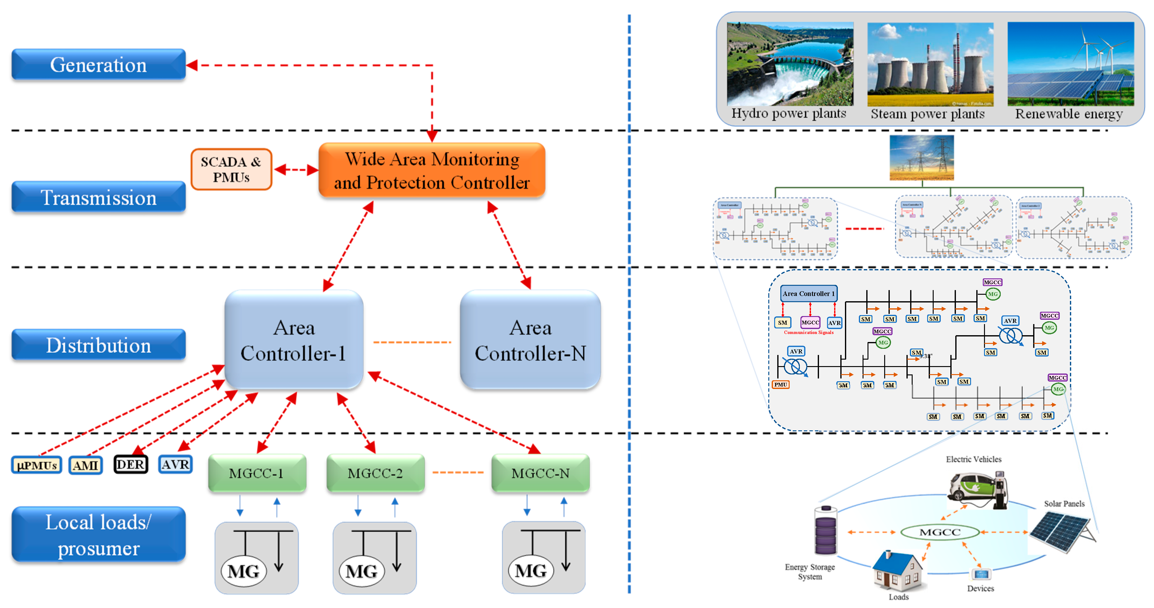
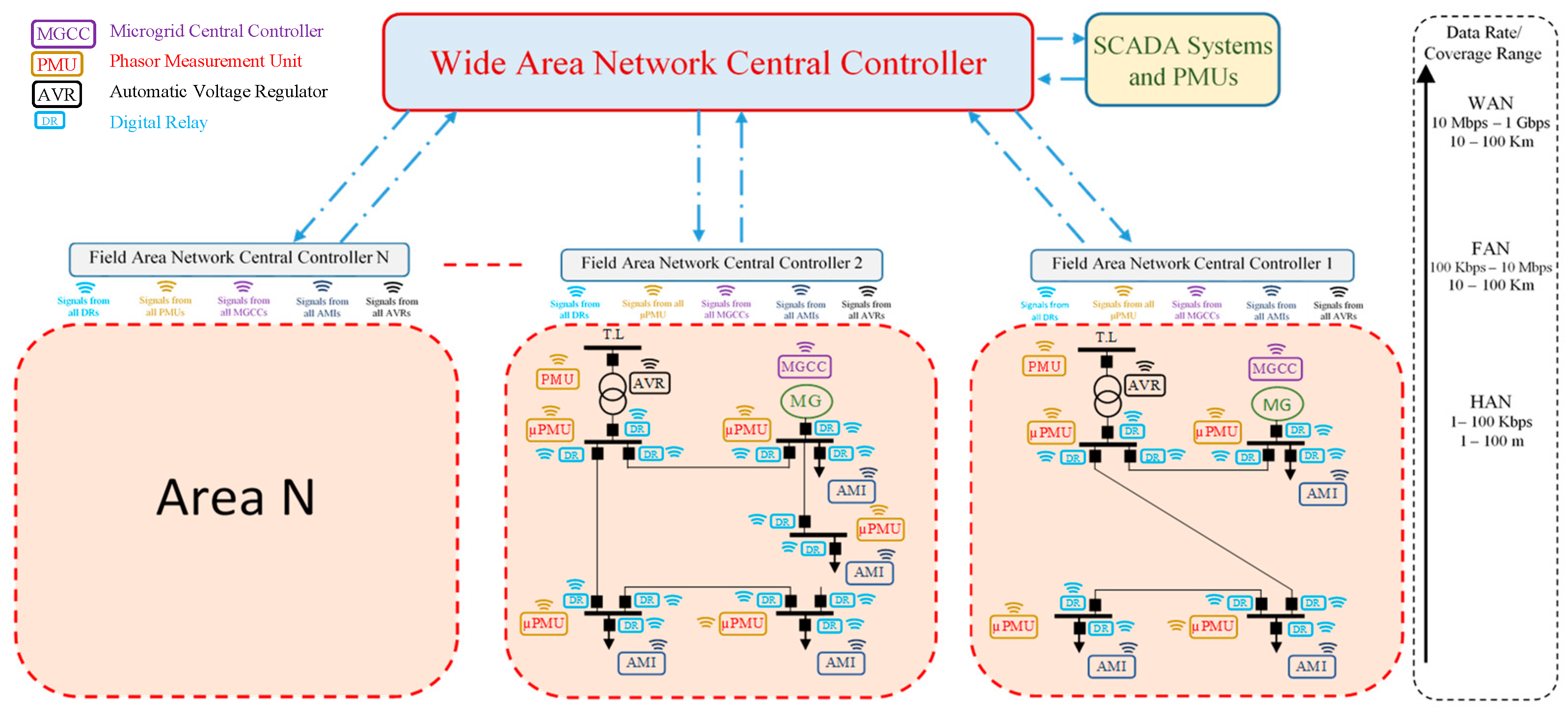
The functional requirements of communication networks, such as permissible latencies, coverage ranges, and data rates, being utilized in MGs, and in smart grids in general, depends on the control layer. For example, within MG communities’ control layer, the coverage ranges are expected to be wider when compared to a single MG’s control layer. For that reason, the communication architectures for smart grids are conceived in a hierarchical multilayered structure; Figure 5 shows an example of a centralized multi-layer hierarchy control for smart grids.
Generically, the communication architecture of the smart grid could be divided into several levels depending on its function and location [64]:
- (1)
- Home Area Network (HAN), which is suitable for short coverage ranges (i.e., up to hundreds of meters), and low communication bandwidths (i.e., up to hundreds of Kbps). HAN is mostly used in smart grid applications at the prosumer level (e.g., communication between MG assets, between smart meters and home appliances, in home automation applications). The common communication protocols used in HAN are mostly WiFi, Zigbee, and Bluetooth [65];
- (2)
- Field Area Network (FAN) is considered to be a portal to transmit information between the HAN and WAN layers. This layer is most suitable for MG communities’ applications, since the coverage ranges could be in Kilometers and the communication bandwidth could reach up to tens of Mbps. It could be realized using WiMax or LTE [66,67]. Utilities uses power line communication (PLC) for long distance communications, for real-time energy management and monitoring, which could also be utilized in FANs. PLC is preferable, since it relies on an existing infrastructure, however, it is prone to noise that is imposed on power lines, especially as the geographic foot print increases. Additionally, RF-mesh is considered to be one of the promising solutions for FAN applications (e.g., AMI applications). Its deployment is relatively cheap, and the utility does not have to rely on telecommunication providers, which introduces more confidentiality. However, these advantages could also be considered as drawbacks, since the absence of unified standard between vendors could degrade the interaction between systems, and RF-mesh has low data rate. Moreover, all radio-based communications are prone to interference, as PLC is vulnerable to noise. However, the remedy in RF-signals could be relatively easy with a mesh, as compared to PLC deploying PLC-gateways at the points showing problems could be challenging and costly [68,69,70];
- (3)
- Wide Area Network (WAN) is the layer where all the aggregated data are being processed and command signals are being sent/received to and from the portal (i.e., FAN) and then to the HAN layer. WAN’s applications are on the power transmission/generation scales since it has wide coverage ranges and considerable communication bandwidths. Fiber optics infrastructure remains to be the first choice for this layer, since it is dealing with high transmission power, but this option is costly when compared to wireless technologies. Table 1 shows some applications in the three different layers of HAN, FAN, and WAN [71,72,73].
Thus, from a communication perspective, the smart grid is a complex cyber-physical system where various electrical devices generate packets, through their microprocessor-based controllers, that are eventually communicated to a controller over a given communication medium. Within this framework, information needs to be transmitted upstream/downstream the communication networks, possibly through gateways, to achieve different functionalities. Although communication networks need to be reliable, the huge amount of traffic, along with other factors that are related to the harsh physical nature of the smart grid, will cause a degradation of ICT performance. This drove researchers from industry and academia to study the performance of ICT on different levels of the communication hierarchy (i.e., WAN, FAN, NAN, and HAN).
Delay is one of the main limitations that is associated with ICTs that raises concerns to electric power engineers and researchers. The sources of delay include [74,75]:
- Processing and queueing
- Congestion of communication links due to high volume of traffic.
- Exhausting computational powers of communicating nodes also due to high volume of traffic.
- Propagation
- Distance between transceivers.
- Obstacles between transceivers, such as trees, buildings.
- Noise and interference from other devices/radio networks.
- Delays due to malicious activity
- Network flooding.
- Complete denial of service.
There are several approaches that one could use to perform delay-impact studies on simulated microgrids, such as [76,77,78,79]:
- Co-simulation. In this approach, software for network simulation is coupled with the power grid simulator to model the behavior of the communication network, which includes the introduction of delays. An example of these software that are used in the engineering literature are Network Simulator (NS) 2 and 3, OPNET, and OMNET++. The clocks of the network simulator and the grid simulators have to be synchronized to achieve realistic operation. This is mostly achieved through a third-party event synchronization tool.
- Network-in-the-loop simulation. In this approach, the control logic is decoupled from the simulation software, and it is implemented on hardware controllers that are interfaced with the power grid simulator through an interface which this simulator allows. There are several works in the literature that are implemented this approach, for purposes other than delay studies, where commercial Intelligent Electronic Devices were interfaced with real-time digital simulators.
In the subsequent sections, we will present a case study illustrating the impact of latency on DC MG operations and that the impact of latency varies with MGs designs. The latency was modeled by intentionally introducing an average delay, representing the average delay that might be associated with the ICT used, to some signals between the MGCC and the LCs
3. DC Microgrid Case Study
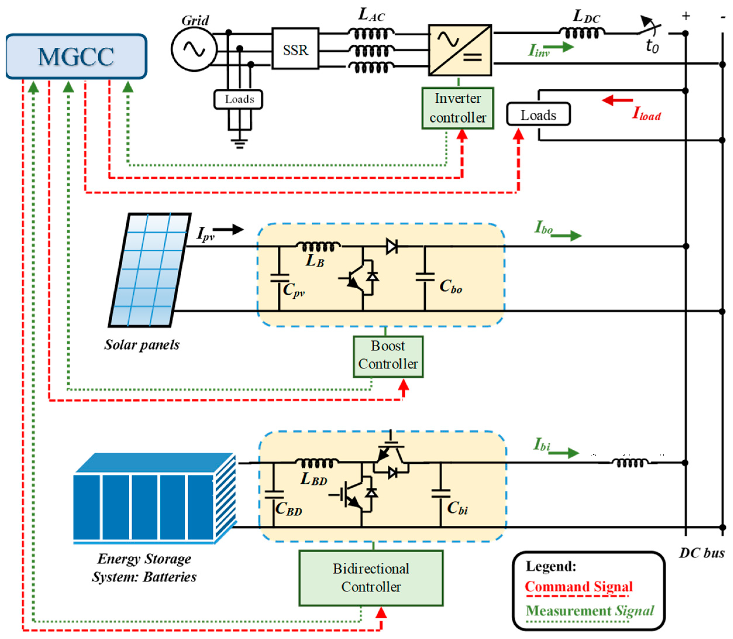
Figure 6 shows the topology of the studied DC microgrid. It is composed of a 6 kW photovoltaic (PV) system and a 1.5 kW battery energy storage system that are connected to the DC bus via a DC-DC step-up converter and a bidirectional DC-DC charger, respectively. Additionally, a grid-tie smart inverter connects the DC microgrid with the AC grid. A total load of 8 kW is connected to the DC microgrids, whose operating voltage is 300 V. A coil was added to the output of the bidirectional converter in order to filter the output current in the islanding mode of the microgrid, when the voltage of the DC bus is regulated by the bidirectional converter. Table 2 tabulates the parameters of the converters (i.e., inductances and capacitances).
As can be seen in Figure 6, each converter has a local control agent. All of the agents communicate with the MGCC, which coordinates their operation and optimizes the performance of the MG. Three microprocessor-based controllers for the three converters present in the system are communicating with the MGCC. We assumed a wireless communication medium, since this paper focuses on emphasizing the impact of the delay on the performance of the DC microgrid itself. Details regarding the microgrid understudy, including the circuits’ design, the components’ values, and the monitoring system, can be found in [4,43,80,81,82,83,84,85,86].
In this study, latency on the signals exchange between the LCs and the MGCC will be introduced in order to analyze the impact of ICT dependence and the consequences on the operation of the MG. Knowing that several case studies could be expanded, in this paper, however, the focus will be on analyzing the critical case where the delay occurs while the MG is shifting from being grid-connected to islanded mode.
Prior to proceeding with the case study, the control actions that were taken by the MGCC to shift to islanded mode will be highlighted/explained. The inverter regulates the voltage of the DC bus before islanding occurs. The MGCC determines the power set-points of the battery system. This indirectly determines the amount of power that is exchanged with the AC grid. However, the boost converters are set to track the maximum power point (MPPT) of the PV system. The inverter is operated in a constant-voltage mode, whereas the battery and the PV systems are in a constant-power mode. Upon the detection of a problem on the main grid side, such as an under frequency/voltage, the MGCC sends two signals, one signal to the digital relay (SSR) at the PCC to disconnect the MG from the AC grid, another signal to the bidirectional converter to regulate the DC bus voltage. If a delay is imposed on the former, the MG remains in the delay, leading to DC bus voltage being floated (i.e., no converter is directly responsible for its regulation). In this situation, the DC bus voltage either starts decreasing or increasing based on the prior operating conditions of the MG. Total power shutdown of the entire MG might occur if these voltage swings hit the protections system’s pick-up thresholds.
4. Control Scheme of the Studied DC Microgrid
Figure 6 shows the control hierarchy of the DC microgrid. It is a centralized-based scheme that is composed of a primary and a secondary layer. In the former (i.e., primary), the LCs continuously monitor the input/output voltages and/or currents of their correspondent converters, depending on the control type, being current, voltage, or MPPT control, which will be commanded by the MGCC. In the latter (i.e., secondary), the MGCC assigns the modes and set points to each LC in order to keep the voltage of the DC bus within the allowable limits, attain optimal operations, while maintaining a reliable operation of the microgrid.
A pre-devised control logic could be implemented within the MGCC for the adopted control scheme (i.e., centralized) to sustain a reliable operation of the DC MG. This control logic might be developed to mitigate the anticipated severe events that the microgrid might encounter, such as islanding. The control of the MG is set up accordingly to increase its preparedness level.
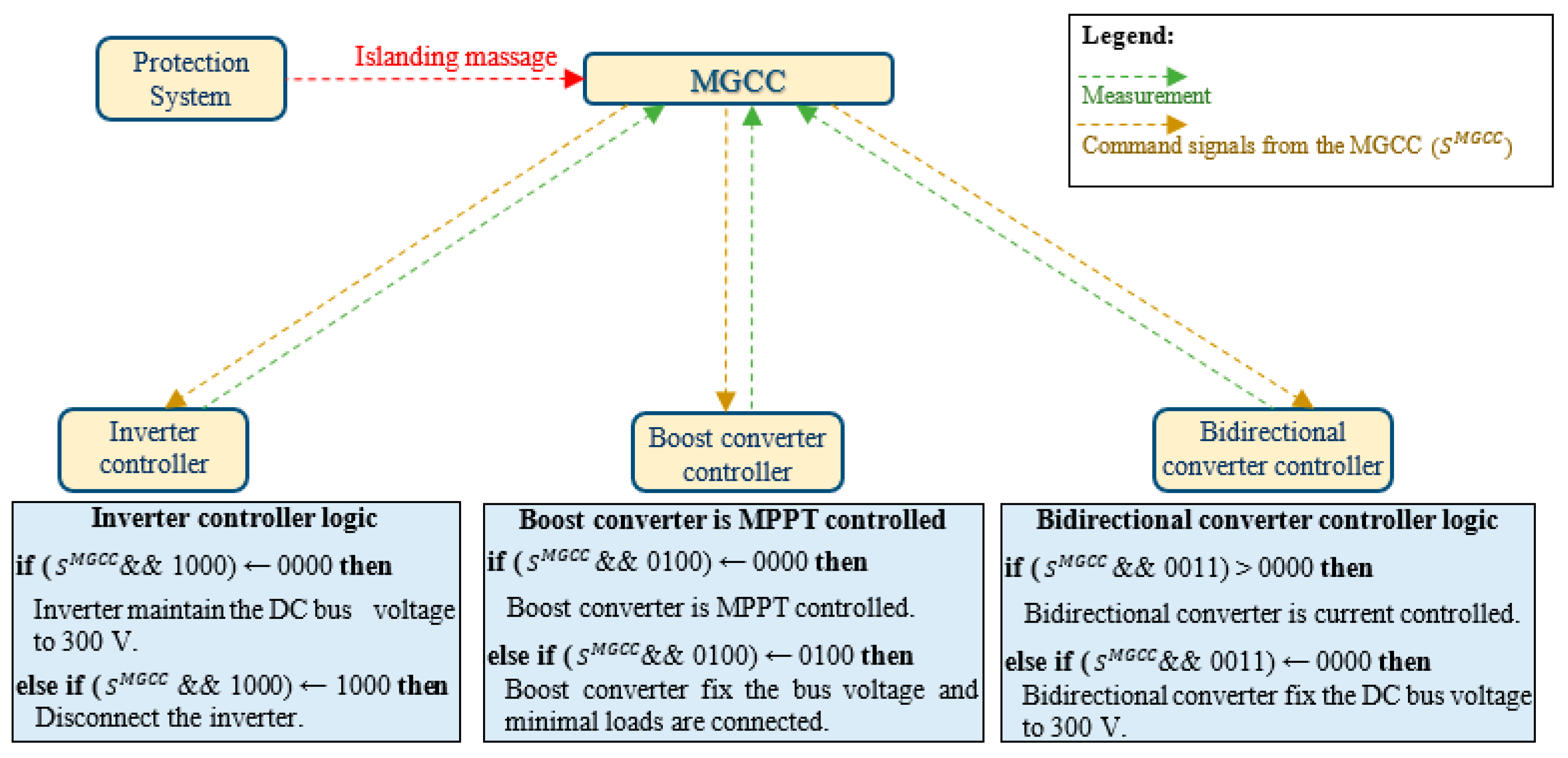
Figure 7 shows the control scheme for the DC microgrid adopted in this paper. The MGCC maintains normal operation while connected to the main grid. The DC bus voltage is fixed at 300 V by the inverter, the boost converter is MPPT-controlled, and the bidirectional converter is current controlled. On the other hand, when the microgrid islands, the protection system sends a signal to the MGCC. In response to this signal, the MGCC sends a signal that is composed of four bits to LCs (SMGCC = 1111), where each bit corresponds to a control type for a specific LC. For instance, the two least significant bits (LSB) variation in SMGCC only correspond to the control type of the bidirectional converter (i.e., 01 and 10 correspond to discharge and charge the battery system with 1C, respectively). The logic implemented on the LC of the bidirectional converter, as shown in Figure 7, is set up to only respond to the two LSBs. Similarly, the LC of the inverter only reacts to the variation of the most significant bit of the SMGCC (e.g., zero corresponds to regulating the bus voltage and one corresponds to disconnecting the MG). In a worst case scenario, if all of the MG’s converters are not connected, the boost converter can be used to maintain the bus voltage, keep in mind during such a scenario, minimum amount of loads should be connected, and these loads should handle voltage variation due to any unexpected intermittency that might occur. In this case, the MGCC commands the LC of the boost converter to regulate the bus voltage by changing the second bit of the SMGCC from zero, which is MPPT-control, to one. Table 3 shows the proportional and integral gains values (i.e., Kp and Ki) for all the controllers.
5. Results and Analysis
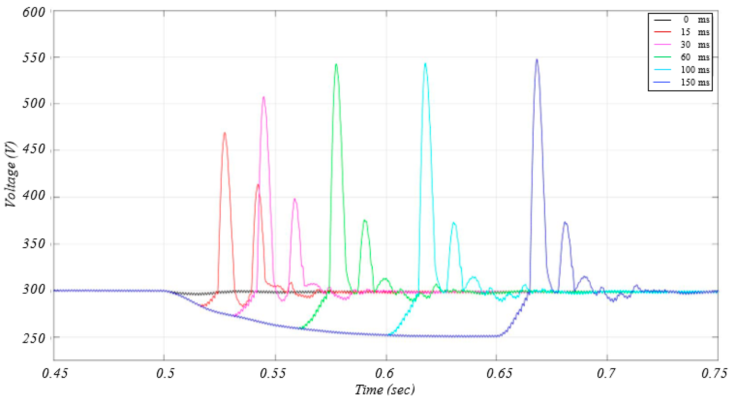
This section presents and analyzes the results of the impact of communication delay on the DC bus voltage () and converters’ switches ( and ). A factor α, which is assumed to simulate the delay, was imposed on SMGC after the protection algorithm islands the microgrid. Table 4 tabulates the average delay of various wireless communication technologies. The islanding occurs at t = 0.5 s. When the delay is considered, no converter is assigned the task of maintaining the voltage of the DC bus.
Figure 8 shows the effect of varying the delay factor α on with constant total capacitance (CT = Cbo + Cbi = 4800 µF) and mismatch current (Im = 7.1 A). Here, the mismatch current refers to the amount of current that is supplied by the main grid to the MG through the inverter right before islanding occurs. Once the MG is islanded, this current has to be supplied by the source whose converter is regulating the DC bus voltage. As can be appreciated from the results, the deviation of the DC bus voltage from the desired value (i.e., 300 V) increases as the delay factor α increases. This leads to an increase in the error of the PI controller of the bidirectional converter. The role of the PI controller is to regulate the DC bus voltage during islanded mode, and an increase in its error causes higher spikes. When considering the average delay values of the HSPA M2M, LTE M2M, and Zigbee wireless communication technologies of Table 4, with the aforementioned values of C and Im, the deviation in the voltage might reach 8.3%, 15%, and 17.3%, respectively. A more drastic scenario could occur if the DERs’ generated power is zero at the instant of islanding since the voltage deviation is also a function of C and Im. This could be possible due to a cloud obscuring sun irradiance from the PV panels in a time where the batteries are depleted and the C is critically small to hold the voltage. Here, the consequences are fast changes at the voltage level, triggering the protection relays of the DC microgrid, which are often based on the rate of change of the voltage and current and/or the voltage limits of (d/dt) of its nominal value [87].
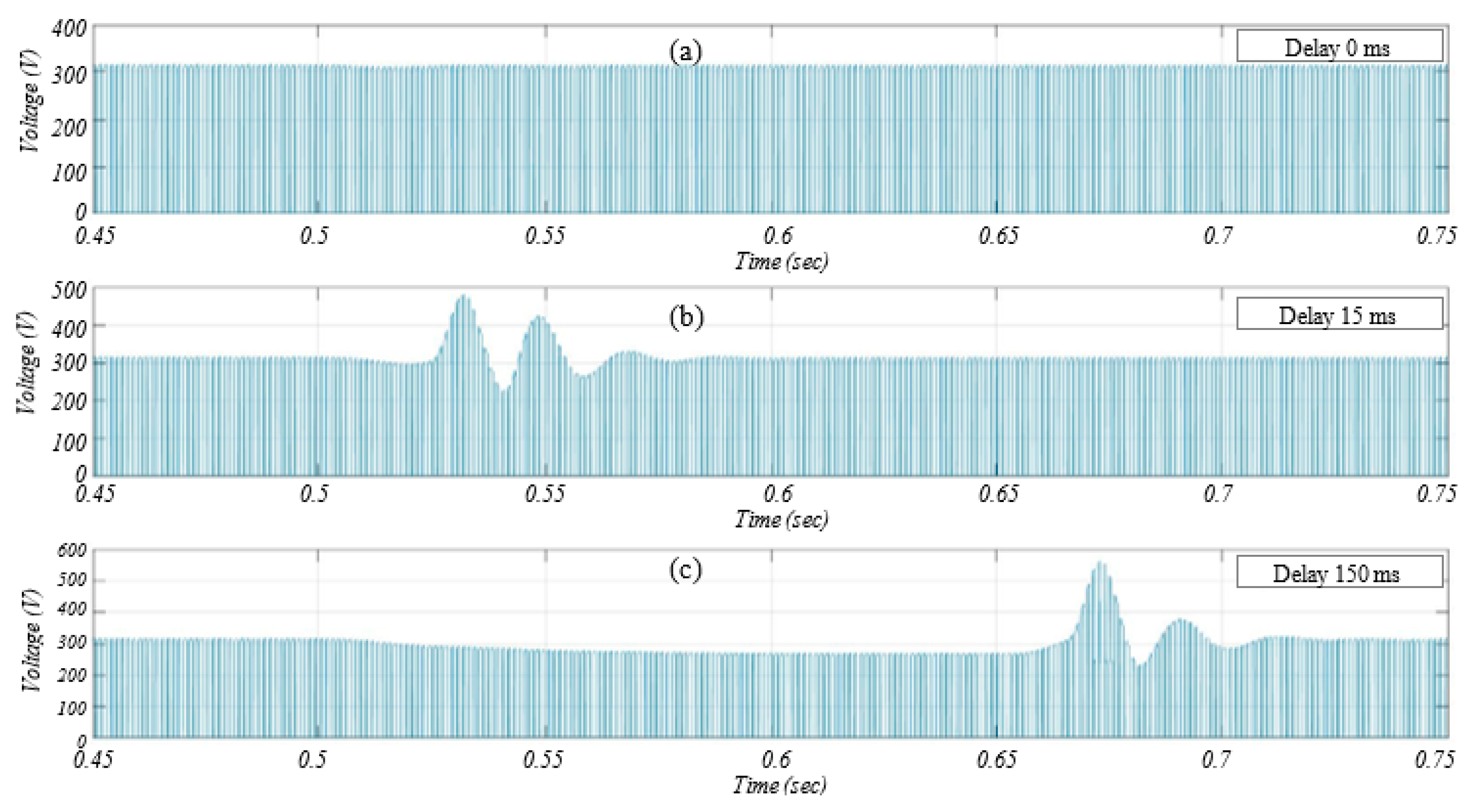
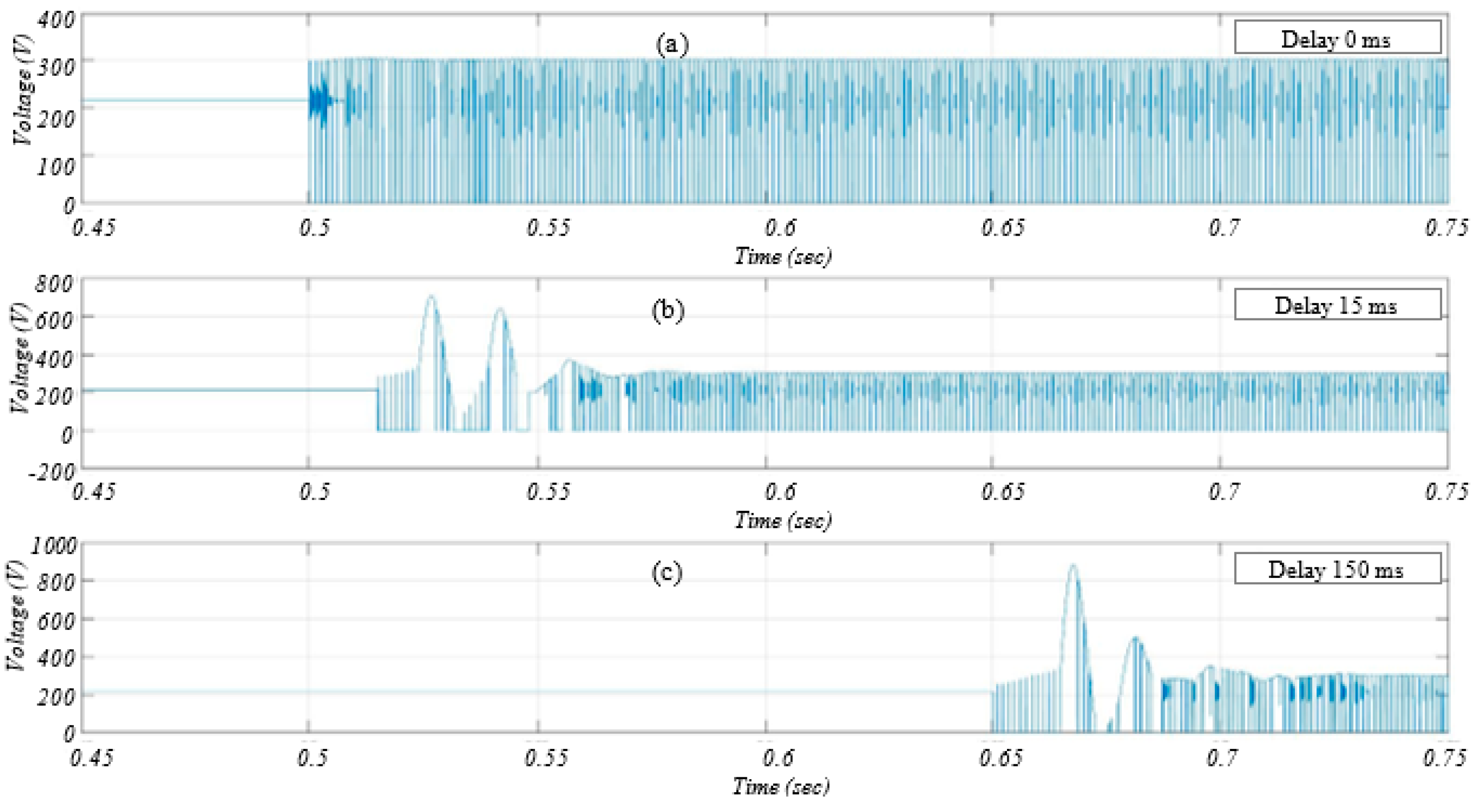
Figure 9a–c show the voltage across Sbo (the boost converter switch) when α = 0, 15, and 150 ms, respectively. As can be appreciated from the results, the voltage across switch is almost the same as the DC bus voltage in Figure 8 if we ignore the voltage of the diode. Additionally, could reach up to more than 1.5 times the nominal value of the DC bus voltage during delays. This peak value depends on the value of total capacitance connected to the DC bus, the ratio of the capacitances of the converters, the values of Ki used in the PI controller responsible for regulating the bus voltage, and the average delay that is associated with the communication technology used, since it impacts the error input to the PI controller. This impact of delay that is associated with the communication technology to be used within the MG should be taken into consideration while designing the boost converter’s switches.
Figure 10a–c show the voltage across Sbi (the bidirectional converter switch) when α = 0, 15, and 150 m, respectively. As can be appreciated from the results, the bidirectional converter was not boosting any current (i.e., the PI controller’s current reference was zero) before t = 0.5 s (i.e., during grid-tie mode), and was almost equal to the voltage of the battery system (210 V). LBD was almost short-circuited, as the bidirectional converter was not operational. In Figure 10b,c, it can be seen that, could stretch to values when the delay ends, which are more than double the nominal . In case the delay lasts longer and there was a current supplying a considerable portion of the DC bus loads (i.e., high mismatch current), might be more than 2.5 the nominal DC bus voltage. This phenomenon could be better explained through the following analysis. The voltage across bidirectional converter’s switch is equal to plus the voltage drop across the diode and the smoothing coil added to enhance the power quality, which can be observed from the circuit model in Figure 6, as shown in (1):
where is the voltage across the series diode in the bidirectional converter, and the voltage across the smoothing coil could be expressed, as follows:
where is the output measured current of the bidirectional converter, which is being controlled through a nested loop, in case the bidirectional converter is supposed to regulate the DC bus voltage. The transfer function of the outer loop for voltage control, during the delay, could be expressed, as follows:
where and are the integral and proportional gains of the outer control loop, respectively.
The transfer function for the inner current loops in the case of charging and discharging the batteries are as shown in (4) and (5), respectively:
where and are the proportional gains of the inner current control loop for charging and discharging, respectively. and are the integral gains of the inner current control loop for charging and discharging, respectively. and are the charging and discharging current references, respectively. The outer loop provides the current reference for the inner loop within the nested PI of the bidirectional converter to regulate the DC bus voltage, which means that the reference currents in (4) and (5) could be replaced by (3), as shown in (6):
As the delay lasts longer, the voltage deviation increases (i.e., ). In other words, the error within the PI controller increases, as shown in (3) and (6). This increased error consequently leads the bidirectional converter to inject more current to regulate the bus voltage, which means higher . Inspecting (2), which leads to higher , which increases and consequently from (1) that increases the voltage across the switch Sbi, might damage the switch if the switch was not properly designed.
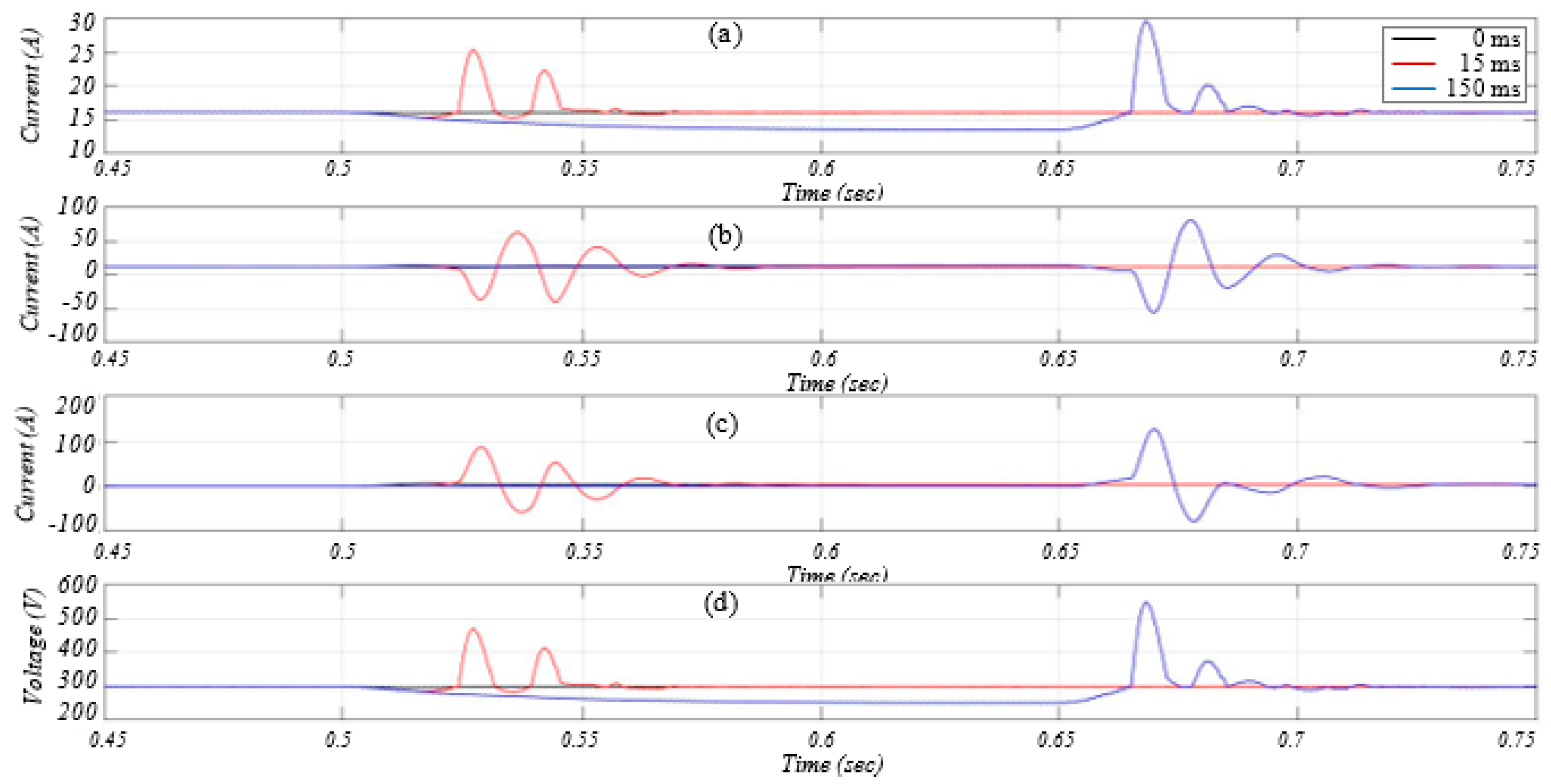
Figure 11a–c depict the effect of different delay intervals on the load current, output current of the boost and bidirectional converters, and the voltage of the DC bus, respectively. As shown in the figures, the PI controller of the bidirectional converter overshoots as soon as the delay α ends, and the LC receives the SMGCC signal to regulate the DC bus voltage. This overshoot is reflected in the boost output current and the current of the load. Additionally, one can notice that an overshoot of around 75 A is injected from the bidirectional converter once the 15 ms delay ends from Figure 11a–c. A temporary 25 A overshoot in load current is thus caused, and boost capacitor absorbs the rest. Additionally, the DC bus voltage and converters current start to oscillate, temporarily, due to the presence of the RLC components within the circuit.
6. Conclusions
This paper presents a detailed survey and breakdown regarding the current status of the literature on the impact of the ICT degradation on the MGs operations and control, and MG control techniques. This paper shows the need for further exploration and analysis of integrating information communication technologies in the microgrids and power grids in order for the smart grid concept to be fully realized. The paper also provides future recommendations regarding research and standardization gaps about ICT integration within MGs.
A case study was presented to demonstrate the impact of the ICT intrinsic-limitations (e.g., delays) on a centrally controlled DC MG operations and control. An analysis of the impact of latency of different wireless communication technologies within HANs on the voltage of the DC MG and the switches of the converters during islanded mode was presented. The behavior of the microgrid against increasing delays was simulated on Simulink. The results showed that the severity varies with the operational conditions of the MG, which is unpredictable, MG converters’ design (e.g., inductors, and switches of the converters), and the duration of the expected delay intervals that are associated with the ICT being utilized within the MG. It is advised that the design of MG should incorporate the limitations of the utilized communication technologies, based on the results of this study. For example, if latency is to be compromised for cost-effectiveness of the communication technology, then more time should be invested on the design and sizing of the MG. Additionally, the results show that, as of yet, using a smoothing inductor for a converter to improve its output power quality could worsen the impact of the delays during severe conditions (e.g., islanding) on the voltage stress of the switches of the converter and the load current. Therefore, microgrids should be thoroughly designed, while deeming ICT expected limitations and protection relay settings.
Author Contributions
M.S. and Y.E. contributed by the results and idea. M.S. wrote the original draft. M.E.H. contributed by writing about the communication aspects. A.M. is the Ph.D. supervisor and proofread the Introduction and portion of the literature review.
Funding
This research was funded by the US National Science Foundation grant number 1846940.
Conflicts of Interest
The authors declare no conflicts of interest.
References
- Wallach, P.A. U.S. Regulation of Greenhouse Gas Emissions. Governance Studies at Brookings: Washington, DC, USA, 2012. Available online: http://www.brookings.edu/research/papers/2012/10/26-climate-change-wallach (accessed on 9 June 2019).
- Integrating Renewable Energy into the Electricity Grid. Available online: http://webcache.googleusercontent.com/search?q=cache:4Pj3nzpeSjwJ:info.aee.net/hubfs/EPA/AEEI-Renewables-Grid-Integration-Case-Studies.pdf%3Ft%3D1440089933677+&cd=4&hl=en&ct=clnk&gl=us (accessed on 23 August 2018).
- Center for Climate and Energy Solutions. Regulating Power Sector Carbon Emissions. Available online: Available online: https://www.c2es.org/content/regulating-power-sector-carbon-emissions/ (accessed on 23 August 2018).
- Saleh, M.; Althaibani, A.; Esa, Y.; Mhandi, Y.; Mohamed, A.A. Impact of clustering microgrids on their stability and resilience during blackouts. In Proceedings of the International Conference on Smart Grid and Clean Energy Technologies (ICSGCE), Offenburg, Germany, 20–23 October 2015; pp. 195–200. [Google Scholar]
- Huang, Y.F.; Werner, S.; Huang, J.; Kashyap, N.; Gupta, V. State estimation in electric power grids: Meeting new challenges presented by the requirements of the future grid. Signal Process. Mag. IEEE 2012, 29, 33–43. [Google Scholar] [CrossRef]
- Smart Grid. Department of Energy. N.p., n.d. Web. June–July 2016. Available online: https://www.energy.gov/science-innovation/electric-power/smart-grid (accessed on 17 July 2019).
- Smart Grid Communications. Available online: https://www.nist.gov/programs-projects/smart-grid-communications-0 (accessed on 17 July 2019).
- Greer, C.; Wollman, D.A.; Prochaska, D.E.; Boynton, P.A.; Mazer, J.A.; Nguyen, C.T.; FitzPatrick, G.J.; Nelson, T.L.; Koepke, G.H.; Hefner, A.R., Jr.; et al. Nist Framework and Roadmap for Smart Grid Interoperability Standards, Release 3.0; US National Institute of Standards and Technology: Gaithersburg, MD, USA, 2014.
- Wu, F.F.; Moslehi, K.; Bose, A. Power system control centers: Past, present, and future. Proc. IEEE 2005, 93, 1890–1908. [Google Scholar] [CrossRef]
- Atzori, L.; Iera, A.; Morabito, G. The internet of things: A survey. Comp. Netw. 2010, 54, 2787–2805. [Google Scholar] [CrossRef]
- Ton, D.T.; Smith, M.A. The U.S. Department of Energy’s microgrid initiative. Electr. J. 2012, 25, 84–94. [Google Scholar] [CrossRef]
- Hatziargyriou, N. (Ed.) Microgrids: Architectures and Control; John Wiley & Sons: Hoboken, NJ, USA, 2013; pp. 4–70. [Google Scholar]
- Shahnia, F.; Bourbour, S.; Ghosh, A. Coupling neighboring microgrids for overload management based on dynamic multicriteria decision-making. IEEE Trans. Smart Grid 2017, 8, 969–983. [Google Scholar] [CrossRef]
- Marnay, C.; Chatzivasileiadis, S.; Abbey, C.; Iravani, R.; Joos, G.; Lombardi, P.; Mancarella, P.; von Appen, J. Microgrid Evolution Roadmap. In Proceedings of the International Symposium on Smart Electric Distribution Systems and Technologies (EDST), Vienna, Austria, 8–11 September 2015. [Google Scholar]
- Elsayed, A.T.; Mohamed, A.A.; Mohammed, O.A. DC microgrids and distribution systems: An overview. Electric Power Syst. Res. 2015, 119, 407–417. [Google Scholar] [CrossRef]
- Wang, F.; Pei, Y.; Boroyevich, D.; Burgos, R.; Ngo, K. AC vs. DC distribution for off-shore power delivery. In Proceedings of the IEEE 34th Annual Conference of IEEE on Industrial Electronics (IECON), Orlando, FL, USA, 10–13 November 2008; pp. 2113–2118. [Google Scholar]
- Hossain, E.; Kabalci, E.; Bayindir, R.; Perez, R. Microgrid testbeds around the world: State of art. Energy Convers. Manag. 2014, 86, 132–153. [Google Scholar] [CrossRef]
- Liu, Z.; Xu, X.; Abdelsalam, H.A.; Makram, E. Power system harmonics study for unbalanced microgrid system with PV sources and nonlinear loads. J. Power Energy Eng. (JPEE) 2015, 3, 43. [Google Scholar] [CrossRef]
- Backhaus, S.N.; Swift, G.W.; Chatzivasileiadis, S.; Tschudi, W.; Glover, S.; Starke, M.; Wang, J.; Yue, M.; Hammerstrom, D. DC Scoping Study—Estimate of Technical and Economic Benefit; LA-UR-15 22097; Los Alamos National Laboratory: Los Alamos, NM, USA, 2015. [Google Scholar]
- Jiayi, H.; Chuanwen, J.; Rong, X. A review on distributed energy resources and MicroGrid. Renew. Sustain. Energy Rev. 2008, 12, 2472–2483. [Google Scholar] [CrossRef]
- Liu, X.; Wang, P.; Loh, P.C. A hybrid AC/DC microgrid and its coordination control. IEEE Trans. Smart Grid 2011, 2, 278–286. [Google Scholar]
- Planas, E.; Andreu, J.; Gárate, J.I.; de Alegría, I.M.; Ibarra, E. AC and DC technology in microgrids: A review. Renew. Sustain. Energy Rev. 2015, 43, 726–749. [Google Scholar] [CrossRef]
- Unamuno, E.; Barrena, J.A. Hybrid AC/DC microgrids—Part I: Review and classification of topologies. Renew. Sustain. Energy Rev. 2015, 52, 1251–1259. [Google Scholar] [CrossRef]
- Sannino, A.; Postiglione, G.; Bollen, M.H. Feasibility of a DC Network for Commercial Facilities. IEEE Trans. Ind. Appl. 2003, 39, 1499–1507. [Google Scholar] [CrossRef]
- Baran, M.E.; Mahajan, N.R. DC Distribution for industrial systems: Opportunities and challenges. IEEE Trans. Ind. Appl. 2003, 39, 1596–1601. [Google Scholar] [CrossRef]
- Salomonsson, D.; Sannino, A. Low-voltage DC distribution system for commercial power systems with sensitive electronic loads. IEEE Trans. Power Deliv. 2007, 22, 1620–1627. [Google Scholar] [CrossRef]
- Majumder, R. Aggregation of microgrids with DC system. Electr. Power Syst. Res. 2014, 108, 134–143. [Google Scholar] [CrossRef]
- Sakurama, K.; Miura, M. Communication-based decentralized demand response for smart microgrids. IEEE Trans. Ind. Electron. 2016, 64, 5192–5202. [Google Scholar] [CrossRef]
- Sahoo, S.; Mishra, S. An adaptive event-triggered communication based distributed secondary control for DC microgrids. IEEE Trans. Smart Grid 2018, 9, 6674–6683. [Google Scholar] [CrossRef]
- Ci, S.; Qian, J.; Wu, D.; Keyhani, A. Impact of wireless communication delay on load sharing among distributed generation systems through smart microgrids. IEEE Wirel. Commun. 2012, 19, 24–29. [Google Scholar] [CrossRef]
- Shafiee, Q.; Dragicevic, T.; Andrade, F.; Vasquez, J.C.; Guerrero, J.M. Distributed consensus-based control of multiple dc-microgrids clusters. In Proceedings of the 40th Annual Conference of the IEEE Industrial Electronics Society (IECON 2014), Dallas, TX, USA, 29 October–1 November 2014; pp. 2056–2062. [Google Scholar] [CrossRef]
- Dragičević, T.; Lu, X.; Vasquez, J.C.; Guerrero, J.M. DC microgrids—Part I: A review of control strategies and stabilization techniques. IEEE Trans. Power Electron. 2016, 31, 4876–4891. [Google Scholar] [CrossRef]
- Johnson, B.K.; Lasseter, R.H.; Alvarado, F.L.; Adapa, R. Expandable multiterminal DC system based on voltage droop. IEEE Trans. Power Deliv. 1993, 8, 1926–1932. [Google Scholar] [CrossRef]
- Nasirian, V.; Moayedi, S.; Davoudi, A.; Lewis, F. Distributed cooperative control of DC microgrids. IEEE Trans. Power Electron. 2015, 30, 2288–2303. [Google Scholar] [CrossRef]
- Ito, Y.; Zhongqing, Y.; Akagi, H. DC microgrid based distribution power generation system. In Proceedings of the 4th International Power Electronics and Motion Control Conference, Xi’an, China, 14–16 August 2004; pp. 1740–1745. [Google Scholar]
- Lu, X.; Guerrero, J.M.; Sun, K.; Vasquez, J.C. An improved droop control method for DC microgrids based on low bandwidth communication with dc bus voltage restoration and enhanced current sharing accuracy. IEEE Trans. Power Electron. 2014, 29, 1800–1812. [Google Scholar] [CrossRef]
- Guerrero, J.M.; Vasquez, J.C.; Matas, J.; De Vicuña, L.G.; Castilla, M. Hierarchical control of droop-controlled ac and dc microgrids—A general approach toward standardization. IEEE Trans. Ind. Electron. 2011, 58, 158–172. [Google Scholar] [CrossRef]
- Nasirian, V.; Davoudi, A.; Lewis, F.L.; Guerrero, J.M. Distributed adaptive droop control for DC distribution systems. IEEE Trans. Energy Convers. 2014, 29, 944–956. [Google Scholar] [CrossRef]
- Shafiee, Q.; Guerrero, J.M.; Vasquez, J.C. Distributed secondary control for islanded microgrids—A novel approach. IEEE Trans. Power Electron. 2014, 29, 1018–1031. [Google Scholar] [CrossRef]
- Wang, P.; Lu, X.; Yang, X.; Wang, W.; Xu, D. An improved distributed secondary control method for DC microgrids with enhanced dynamic current sharing performance. IEEE Trans. Power Electr. 2016, 31, 6658–6673. [Google Scholar] [CrossRef]
- Vu, T.V.; Paran, S.; Diaz-Franco, F.; El-Mezyani, T.; Edrington, C.S. An alternative distributed control architecture for improvement in the transient response of DC microgrids. IEEE Trans. Ind. Electron. 2017, 64, 574–584. [Google Scholar] [CrossRef]
- Guo, F.; Xu, Q.; Wen, C.; Wang, L.; Wang, P. Distributed secondary control for power allocation and voltage restoration in islanded DC microgrids. IEEE Trans. Sustain. Energy 2018, 9, 1857–1869. [Google Scholar] [CrossRef]
- Saleh, M.; Esa, Y.; Mohamed, A. Communication based control for DC microgrids. IEEE Trans. Smart Grid 2018, 10, 2180–2195. [Google Scholar] [CrossRef]
- Marwali, M.; Jung, J.; Keyhani, A. Control of distributed generation systems-part II: Load sharing control. IEEE Trans. Power Electron. 2004, 9, 1551–1561. [Google Scholar] [CrossRef]
- Byun, Y.B.; Koo, T.G.; Joe, K.Y.; Kim, E.S.; Seo, J.I.; Kim, D.H. Parallel operation of three-phase UPS inverters by wireless load sharing control. In Proceedings of the Twenty-Second International Telecommunications Energy Conference (Cat. No.00CH37131), Phoenix, AZ, USA, 10–14 September 2000; pp. 526–532. [Google Scholar]
- Marwali, M.N.; Jung, J.W.; Keyhani, A. Control of distributed generation systems-part I: Load sharing control. IEEE Trans. Power Electron. 2004, 19, 1541–1550. [Google Scholar] [CrossRef]
- Wu, D.; Ci, S.; Wang, H.; Katsaggelos, A.K. Application-centric routing for video streaming over multi-hop wireless networks. IEEE Trans. Circuits Syst. Video Tech. 2010, 20, 1721–1734. [Google Scholar] [CrossRef]
- Zhong, Q.; Weiss, G. A Unified smith predictor based on the spectral decomposition of the plant. Int. J. Control 2004, 77, 1362–1371. [Google Scholar] [CrossRef]
- Shafiee, Q.; Dragičević, T.; Vasquez, J.C.; Guerrero, J.M. Hierarchical control for multiple DC-microgrids clusters. IEEE Trans. Energy Convers. 2014, 29, 922–933. [Google Scholar] [CrossRef]
- Lai, J.; Zhou, H.; Hu, W.; Lu, X.; Zhong, L. Synchronization of hybrid microgrids with communication latency. Math. Probl. Eng. 2015, 2015, 10. [Google Scholar] [CrossRef]
- Macana, C.A.; Mojica-Nava, E.; Quijano, N. Time-delay effect on load frequency control for microgrids. In Proceedings of the 2013 10th IEEE International Conference on Networking, Sensing and Control (ICNSC), Evry, France, 10–12 April 2013; pp. 544–549. [Google Scholar] [CrossRef]
- Ebenbauer, C.; Allgower, F. Stability analysis for time-delay systems using rekasius’s substitution and sum of squares. In Proceedings of the 45th IEEE Conference on Decision and Control, San Diego, CA, USA, 13–15 December 2006; pp. 5376–5381. [Google Scholar] [CrossRef]
- Liu, S.; Wang, X.; Liu, P.X. Impact of communication delays on secondary frequency control in an islanded microgrid. IEEE Trans. Ind. Electron. 2015, 62, 2021–2031. [Google Scholar] [CrossRef]
- Wang, X.; Freitas, W.; Dinavahi, V.; Xu, W. Investigation of positive feedback anti-islanding control for multiple inverter-based distributed generators. IEEE Trans. Power Syst. 2009, 24, 785–795. [Google Scholar] [CrossRef]
- Tonkoski, R.; Turcotte, D.; L-Fouly, T.H.M.E. Impact of high PV penetration on voltage profiles in residential neighborhoods. IEEE Trans. Sustain. Energy 2012, 3, 518–527. [Google Scholar] [CrossRef]
- Dick, E.P.; Narang, A. Canadian Urban Benchmark Distribution System; Varennes CETC: Varennes, QC, Canada, 2005; pp. 2005–2121. [Google Scholar]
- Saleh, M.; Esa, Y.; Mohamed, A. Impact of communication latency on the bus voltage of centrally controlled DC microgrid during islanding. IEEE Trans. Sustain. Energy 2018, 1. [Google Scholar] [CrossRef]
- Ancillotti, E.; Bruno, R.; Conti, M. The role of communication systems in smart grids: Architectures, technical solutions and research challenges. Comp. Commun. 2013, 36, 1665–1697. [Google Scholar] [CrossRef] [Green Version]
- Fan, Z.; Kulkarni, P.; Gormus, S.; Efthymiou, C.; Kalogridis, G.; Sooriyabandara, M.; Zhu, Z.; Lambotharan, S.; Chin, W.H. Smart grid communications: Overview of research challenges, solutions, and standardization activities. IEEE Commun. Surv. Tutor. 2013, 15, 21–38. [Google Scholar] [CrossRef]
- IEEE. Guide for Monitoring, Information Exchange, and Control of Distributed Resources Interconnected with Electric Power Systems; IEEE Std 1547.3-2007; IEEE: New York, NY, USA, 2007; pp. 1–160. [Google Scholar]
- Ku, T.; Park, W.; Choi, H. IoT energy management platform for microgrid. In Proceedings of the 2017 IEEE 7th International Conference on Power and Energy Systems (ICPES), Toronto, ON, Canada, 1–3 November 2017; pp. 106–110. [Google Scholar] [CrossRef]
- Majee, A.; Swathika, O.V.G. IoT based reconfiguration of microgrids through an automated central protection centre. In Proceedings of the 2017 International Conference on Power and Embedded Drive Control (ICPEDC), Chennai, India, 16–18 March 2017; pp. 93–97. [Google Scholar] [CrossRef]
- IoT-Based State Estimation for Microgrids—IEEE Journals & Magazine. Available online: https://ieeexplore.ieee.org/document/8255584 (accessed on 5 November 2018).
- Kuzlu, M.; Pipattanasomporn, M.; Rahman, S. Communication network requirements for major smart grid applications in HAN, NAN and WAN. Comput. Netw. 2014, 67, 74–88. [Google Scholar] [CrossRef]
- Safdar, S.; Hamdaoui, B.; Cotilla-Sanchez, E.; Guizani, M. A Survey on Communication Infrastructure for Micro-grids. In Proceedings of the 2013 9th International Wireless Communications and Mobile Computing Conference (IWCMC), Sardinia, Italy, 1–5 July 2013; pp. 545–550. [Google Scholar]
- Llaria, A.; Terrasson, G.; Curea, O.; Jimenez, J. Application of Wireless Sensor and Actuator Networks to Achieve Intelligent Microgrids: A Promising Approach towards a Global Smart Grid Deployment. Appl. Sci. 2016, 6, 61. [Google Scholar] [CrossRef]
- Kuzlu, M. Assessment of communication technologies and network requirements for major smart grid applications. In Proceedings of the 2013 IEEE PES innovative smart grid technologies conference (ISGT), Washington, DC, USA, 24–27 February 2013. [Google Scholar]
- Lichtensteiger, B.; Bjelajac, B.; Müller, C.; Wietfeld, C. RF mesh systems for smart metering: System architecture and performance. In Proceedings of the 2010 IEEE International Conference on Smart Grid Communications (SmartGridComm), Gaithersburg, MD, USA, 4–6 October 2010. [Google Scholar]
- Malandra, F.; Sanso, B. PeRF-Mesh: A performance analysis tool for large scale RF-mesh-based smart meter networks with FHSS. In Proceedings of the 2015 IEEE International Conference on Smart Grid Communications (SmartGridComm), Miami, FL, USA, 2–5 November 2015; pp. 792–797. [Google Scholar] [CrossRef]
- White, B. Power Line Communications vs. Radio Frequency Communications. September 2018. Available online: https://www.cimconlighting.com/blog/power-line-communications-vs.-radio-frequency-communications (accessed on 17 July 2019).
- Webster, R.; Munasinghe, K.; Jamalipour, A. Optimal resource allocation for smart grid applications in high traffic wireless networks. In Proceedings of the 2014 IEEE International Conference on Smart Grid Communications (SmartGridComm), Venice, Italy, 3–6 November 2014; pp. 398–403. [Google Scholar] [CrossRef]
- Emmanuel, M.; Seah, W.K.G.; Rayudu, R. Communication Architecture for Smart Grid Applications. Available online: https://ecs.victoria.ac.nz/foswiki/pub/Groups/WiNe/ResearchPublications/architecture_embfonts.pdf (accessed on 17 July 2019).
- Communication technologies and networks for Smart Grid and Smart Metering By CDG 450 Connectivity Special Interest Group (450 SIG). Available online: http://www.cdg.org/resources/files/white_papers/CDG450SIG_Communication%20_Technologies_Networks_Smart_Grid_Smart_Metering_SEPT2013.pdf (accessed on 30 July 2019).
- Zhang, B.; Ng, T.S.; Nandi, A.; Riedi, R.; Druschel, P.; Wang, G. Measurement-Based Analysis, Modeling, and Synthesis of the Internet Delay Space. Study at Rice University. Available online: https://www.cs.rice.edu/~eugeneng/papers/IMC06.pdf (accessed on 10 June 2019).
- Rubin, I. Path delays in communication networks. Appl. Math. Optim. 1975, 1, 193–221. [Google Scholar] [CrossRef]
- Albagli, A.N.; Falcão, D.M.; de Rezende, J.F. Smart grid framework co-simulation using HLA architecture. Electr. Power Syst. Res. 2016, 130, 22–33. [Google Scholar] [CrossRef]
- Bhor, D.; Angappan, K.; Sivalingam, K.M. Network and power-grid co-simulation framework for Smart Grid widearea monitoring networks. J. Netw. Comp. Appl. 2016, 59, 274–284. [Google Scholar] [CrossRef]
- Boroojeni, K.; Amini, M.H.; Nejadpak, A.; Dragičević, T.; Iyengar, S.S.; Blaabjerg, F. A novel cloud-based platform for implementation of oblivious power routing for clusters of microgrids. IEEE Access 2017, 5, 607–619. [Google Scholar] [CrossRef]
- Celli, G.; Pegoraro, P.A.; Pilo, F.; Pisano, G.; Sulis, S. DMS cyberphysical simulation for assessing the impact of state estimation and communication media in smart grid operation. IEEE Trans. Power Syst. 2014, 29, 2436–2446. [Google Scholar] [CrossRef]
- Saleh, M.; Esa, Y.; Mohamed, A. Hardware based testing of communication based control for dc microgrid. In Proceedings of the International Conference on Renewable Energy Research and Applications (ICRERA), San Diego, CA, USA, 5–8 November 2017. [Google Scholar]
- Saleh, M.; Esa, Y.; Mhandi, Y.; Brandauer, W.; Mohamed, A. Design and implementation of CCNY DC microgrid testbed. In Proceedings of the 2016 IEEE Industry Applications Society Annual Meeting, Portland, OR, USA, 2–6 October 2016. [Google Scholar]
- Saleh, M.; Esa, Y.; Moahmed, A. Centralized control for DC microgrid using finite state machine. In Proceedings of the IEEE Innovative Smart Grid Technologies Conference (ISGT), Washington, DC, USA, 23–26 April 2017. [Google Scholar]
- Saleh, M.; Esa, Y.; Mohamed, A. Application of complex network analysis in electric power systems. Energies 2018, 11, 1381. [Google Scholar] [CrossRef]
- Saleh, M.; Esa, Y.; Moahmed, A. Energy management algorithm for resilient controlled delivery grids. In Proceedings of the Industry and Application Society (IAS) Conference, Cincinnati, OH, USA, 1–5 October 2017. [Google Scholar]
- Saleh, M.; Dutta, O.; Esa, Y.; Moahmed, A. Quantitative analysis of regenerative energy in electric rail traction systems. In Proceedings of the Industry and Application Society (IAS) Conference, Cincinnati, OH, USA, 1–5 October 2017. [Google Scholar]
- Saleh, M.; Esa, Y.; Mohamed, A. Optimal microgrids placement in electric distribution systems using complex network framework. In Proceedings of the International Conference on Renewable Energy Research and Applications (ICRERA), San Diego, CA, USA, 5–8 November 2017. [Google Scholar]
- Choi, J.; Jeong, H.; Choi, J.; Won, D.; Ahn, S.; Moon, S. Voltage control scheme with distributed generation and grid connected converter in a DC microgrid. Energies 2014, 7, 6477–6491. [Google Scholar] [CrossRef]
- Sherazi, H.; Iqbal, R.; Hassan, S.; Chaudary, M.; Gilani, S. ZigBee’s received signal strength and latency evaluation under varying environments. J. Comp. Netw. Commun. 2016, 2016, 8. [Google Scholar] [CrossRef]
- Laner, M.; Svoboda, P.; Romirer, P.; Nikaein, N.; Ricciato, F. A comparison between one-way delays in operating HSPA and LTE networks. In Proceedings of the 2012 10th International Symposium on Modeling and Optimization in Mobile, Ad Hoc and Wireless Networks (WiOpt), Paderborn, Germany, 14–18 May 2012. [Google Scholar]
- Swappa: Reti Wireless—Zigbee. N.p., n.d. Web. October–November 2016. Available online: http://www.swappa.it/wiki/Uni/RW-13Aprile (accessed on 17 July 2019).
Figure 1.
Electric power system: (a) the conventional version and (b) the smart grid version.

Figure 2.
Envisioned smart grid: (Right) centralized control hierarchy and (Left) the infrastructure evolution.
Figure 2.
Envisioned smart grid: (Right) centralized control hierarchy and (Left) the infrastructure evolution.

Figure 3.
Block diagram examples of: (a) DC, (b) AC, and (c) hybrid microgrids.

Figure 4.
Examples of: (a) decentralized droop control, (b) centralized control, and (c) distributed communication-based control.
Figure 4.
Examples of: (a) decentralized droop control, (b) centralized control, and (c) distributed communication-based control.

Figure 5.
Conceived centralized multi-layer control hierarchy for smart grids.

Figure 6.
DC Microgrid model understudy.

Figure 7.
Control scheme and logics implemented for the DC MG during grid-tie and islanded modes.

Figure 8.
Variation of the DC bus voltage with different α, CT = 4800 µF and Im = 7.1 A.

Figure 9.
Impact of delay on the boost converter switch Sbo, CT = 4800 µF and Im = 7.1 A: (a) during grid-tie, (b) for a delay of 15 ms, and (c) for a delay of 150 ms.
Figure 9.
Impact of delay on the boost converter switch Sbo, CT = 4800 µF and Im = 7.1 A: (a) during grid-tie, (b) for a delay of 15 ms, and (c) for a delay of 150 ms.

Figure 10.
Impact of delay on the bidirectional converter switch Sbi, CT = 4800 µF and Im = 7.1 A: (a) in grid-tie, (b) with a 15 ms delay, and (c) with a 150 ms delay.
Figure 10.
Impact of delay on the bidirectional converter switch Sbi, CT = 4800 µF and Im = 7.1 A: (a) in grid-tie, (b) with a 15 ms delay, and (c) with a 150 ms delay.

Figure 11.
Shows the impact of different delays with CT = 4800 µF and Im = 7.1 A on (a) load current, (b) boost converter output current, (c) bidirectional output current, and (d) DC bus voltage.
Figure 11.
Shows the impact of different delays with CT = 4800 µF and Im = 7.1 A on (a) load current, (b) boost converter output current, (c) bidirectional output current, and (d) DC bus voltage.


Table 1.
Home Area Network (HAN), Field Area Network (FAN), and Wide Area Network (WAN) layers’ applications, allowable delays, and utilized communication technologies.
Table 1.
Home Area Network (HAN), Field Area Network (FAN), and Wide Area Network (WAN) layers’ applications, allowable delays, and utilized communication technologies.
| Home Area Network | ||
| Example of Applications | Average Allowable Latency Ranges | Communication Technologies |
| Microgrids | msec.–sec. |
|
| Building automation | seconds | |
| Field Area Network | ||
| Pricing | <1 min |
|
| Demand response | <1 min | |
| Electric transportation (e.g., pricing info, charge status) | <15 s | |
| Wide Area Network | ||
| Adaptive islanding | <0.1 s |
|
| Voltage stability monitoring | <5 s | |
Table 2.
Inductances and Capacitance of the Converters of the DC microgrid (MG).
| Converter | Component | Value |
|---|---|---|
| Bidirectional converter | LBD | 4.5 mH, 0.25 Ohm |
| CBD | 890 μF | |
| Smoothing coil | 8 mH, 1 Ohm | |
| Boost converter | LB | 4.5 mH, 0.25 Ohm |
| Cpv | 1200 μF | |
| Inverter | LDC | 19 m H, 1.4 Ohm |
| CDC | 1488 μF | |
| LAC | 3-phase each (19 mH, 1 Ohm) |
Table 3.
Proportional and Integral Gains of Various Control Technique Used in the Studied DC MG.
| Converter | Control Technique | Outer Loop | Inner Loop | ||||
|---|---|---|---|---|---|---|---|
| Charge | Discharge | ||||||
| Kp | Ki | Kp | Ki | Kp | Ki | ||
| Bidirectional converter | Current control | N/A | N/A | 0.02 | 110 | 0.02 | 3 |
| Voltage control | 3 | 1 | 0.002 | 10 | 0.02 | 3 | |
| Outer Loop | Id | Iq | |||||
| Inverter | Voltage control | 0.1 | 10 | 192.1 | 97671 | 192.1 | 97671 |
© 2019 by the authors. Licensee MDPI, Basel, Switzerland. This article is an open access article distributed under the terms and conditions of the Creative Commons Attribution (CC BY) license (http://creativecommons.org/licenses/by/4.0/).
Share and Cite
MDPI and ACS Style
Saleh, M.; Esa, Y.; Hariri, M.E.; Mohamed, A. Impact of Information and Communication Technology Limitations on Microgrid Operation. Energies 2019, 12, 2926. https://doi.org/10.3390/en12152926
AMA Style
Saleh M, Esa Y, Hariri ME, Mohamed A. Impact of Information and Communication Technology Limitations on Microgrid Operation. Energies. 2019; 12(15):2926. https://doi.org/10.3390/en12152926
Chicago/Turabian StyleSaleh, Mahmoud, Yusef Esa, Mohamed El Hariri, and Ahmed Mohamed. 2019. "Impact of Information and Communication Technology Limitations on Microgrid Operation" Energies 12, no. 15: 2926. https://doi.org/10.3390/en12152926
Note that from the first issue of 2016, this journal uses article numbers instead of page numbers. See further details here.