Use of Discharge Resistor to Improve Transient De-Excitation in Brushless Synchronous Machines


1
Department of Electrical Engineering, ETS Ingenieros Industriales, Universidad Politécnica de Madrid, C/José Gutierrez Abascal, 2, 28006 Madrid, Spain
2
Department of Electrical Engineering, ETS Ingeniería y Diseño Industrial, Universidad Politécnica de Madrid, C/Ronda de Valencia, 3, 28012 Madrid, Spain
*
Author to whom correspondence should be addressed.
Energies 2019, 12(13), 2528; https://doi.org/10.3390/en12132528
Submission received: 3 June 2019
/
Revised: 26 June 2019
/
Accepted: 27 June 2019
/
Published: 1 July 2019
Abstract
:The discharge resistor is only used in case of electrical trip to reduce the field current as fast as possible and to minimize the damages produced by the short-circuit current supplied by the synchronous machine. The connection of the discharge resistor is done by opening the field breaker and it implies a large negative voltage in the field winding. This negative voltage is limited to 80% of the winding insulation voltage. On the other hand, in case of a transient de-excitation, at the first moment, the automatic voltage regulator (AVR) reduces the field voltage to the minimum. In case of one-quadrant rectifier type AVR, the minimum voltage is zero and in case of two-quadrant rectifier AVR, the minimum voltage is close to the ceiling voltage with negative polarity. In both cases, the minimum voltages are much smaller than the negative voltage produced by the connection of the discharge resistor. This paper presents a new system that improves the transient de-excitation of synchronous machines using the discharge resistor by an additional static field breaker (SFB). The control of the static field breaker and consequently the connection and disconnection of the discharge resistor is done based on the output field voltage supplied by the AVR. This allows the exciter field current to be reduced in a faster way and continue with the normal operation of the machine after the transient. In this study, the correct operation of the additional static field breaker (SFB) has been validated by computer simulations and experimental test in a 15 MVA generator comprising a commercial one-quadrant rectifier AVR type obtaining excellent results.
1. Introduction
Nowadays there are mainly two excitation systems in the market, static and brushless [1]. The static excitation system directly feeds the field winding of the synchronous machine, hence requires slipping rings and brushes which creates problems for maintenance [2]. However, the control of the field current could be performed in a fast way, so the transient response is swift [3].
On the other hand, the brushless excitation systems require an additional electrical machine, called exciter, which feeds the field winding of the main machine [4,5,6]. This system does not require slipping rings or brushes; however, the field winding is not accessible for de-excitation [7,8].
One of the main disadvantages of brushless synchronous machines is that the rotating diodes do not allow a fast de-excitation, as the minimum voltage in the diode bridge is zero. Numerous systems have been developed to address this issue. One very common technique is the use of a rotating resistor [9,10,11]. Other techniques are based on rotating controlled bridges [12,13]. These methods have very complex control systems which require trusted communication between the stator and the rotor.
Mixed excitation systems have also been developed and it is a very active research line [14] in order to combine the static and brushless system advantages.
There are other research lines to improve the operation excitation system for synchronous machines based on the use of subharmonic excitation [15], improving the rotor design [16], or nonlinear excitation control [17].
In a previous study, in order to solve the problem of the rotating diodes bridge, one of the de-excitation techniques based on a rotating resistor was developed by the authors [18,19]. This system, called high-speed brushless de-excitation system (HSBDS) for synchronous machines, is based on a novel brushless configuration that includes an autonomous control card mounted in the rotor which governs series of static switches and a discharge resistor which accelerates the field current suppression. Originally the HSBDS was developed for reducing the short-circuit current supplied by the machine and it was tested in a 5-kVA laboratory bench where it has proven its operation.
Afterward, the HSBDS was improved and commissioned in real generation units. In Reference [20] the necessary changes needed to scale the HSBDS from 5 kVA of the laboratory bench until 20 MVA of a hydro generator were detailed. In the 20 MVA generator, the no-load de-excitation time constant had been decreased by 4 times from the conventional brushless operation.
The inverse voltage of the semiconductors used as static switches has been investigated to improve the transient response of the HSBDS [21]. Moreover, thanks to a 15 MVA synchronous laboratory machine, the HSBDS has been tested in a large size commercial generator under short-circuit conditions [22] with excellent results. In this 15 MVA generator, the three-phase internal short-circuit energy (i2t) was reduced by 12.5 times thanks to the use of the HSBDS.
Another problem of brushless excitation system is the additional time constant imposed by the additional machine, the exciter. This paper deals with this problem.
In this paper, a new research line is presented. It consists of the use of the discharge resistor in transient operation and not only in case of electrical trip, as it is normally done. The discharge resistor will be connected for de-excitation purpose and afterward disconnected, and the machine will continue with the normal operation. It is necessary for an additional static field breaker (SFB).
In this work, we present an autonomous system to control the discharge resistor, based on a commercial microcontroller. Moreover, as a static field breaker, we use a static DC relay joined to the conventional field breaker. The experimental tests have been carried out in a brushless 15 MVA generator where the HSBDS was previously installed. So, we also present tests of both systems working together.
This paper is structured as follows: Section 2 summarizes the problem of the brushless de-excitation. Section 3 details the principles of the proposed de-excitation system based on the transient use of the discharge resistor and an additional static field breaker (SFB). Section 4 shows the results of the computer simulations of the new de-excitation system for a brushless hydro generator. Section 5 presents the experimental results of the tests done in a 15 MVA synchronous generator. And finally, Section 6 concludes with the main contributions of the paper.
2. De-Excitation of Brushless Synchronous Machines. Description of the Problem and State of the Art
2.1. De-Excitation of Brushless Synchronous Machines Process
Despite its advantages, a brushless excitation system has a poorer transient response compared to the static system as the exciter introduces an extra time constant to the main synchronous machine constant. Another reason is the use of rotating diodes which does not allow the field winding to get negative voltage feed.
In synchronous machines, the transient behavior of the field current is characterized by the transient time constant (1), that depends on the field winding impedance (Rf, Lf), the rotor–stator coupling (Mf), and the stator winding inductance (Ld). At no-load condition, the time constant (2) only depends on the field winding impedance, that is the ratio between inductance (Lf) and resistance (Rf). In any case, the time constants are inversely proportional to the resistance of the field winding.
These time constants determine the de-excitation process in the event of a transient de-excitation or in case of internal failure in a synchronous machine. In case a discharge resistor (Rd) was connected, the time constant of the machine diminishes, as presented in (3) and (4).
The higher the value of the discharge resistor (Rd), the lower is the de-excitation time. However, the voltage in the rotor is proportional to the discharge resistor and the excitation current at the beginning of the de-excitation. So, the maximum value of the discharge resistor (Rd) should not damage the rotor insulation. In the case of the static excitation system, the connection of a discharge resistor can be done easily, so the transient response in case of field suppression is excellent.
The behavior of the brushless synchronous machines is worse for three reasons: first, the exciter (another additional synchronous machine) that enlarges the time constants; second, the absence of brushes does not easily connect the auxiliary circuit for field suppression; and third, the rotating diodes prevent the rotor from negative voltage feed.
For brushless synchronous machines, the usual value of the time constant is in the range of 0.5–1 s for T’d (1) and 5–9 s for T’d0 (2). So, in case of an internal failure in the machine, the damage will probably be critical, even if the electrical protection system operates correctly, as the current supplied by the machine will last several seconds.
2.2. Brushless De-Excitation System State of the Art
The de-excitation, in case of electrical trip, is done using a discharge resistor connected by the field breaker. There are mainly two different configurations depending on the field breaker and type of rectifier, as shown in Figure 1 and Figure 2.
In Figure 1 an automatic voltage regulator (AVR) one-quadrant Insulated Gate Bipolar Transistor (IGBT) rectifier type is shown in combination with a single pole field breaker. In this configuration, the discharge resistor is connected when the field breaker is open in case of shutdown. While in case of transient de-excitation the minimum voltage supply by the AVR is zero, consequently the de-excitation of the field winding of the exciter is not very fast.
In Figure 2 two-quadrant thyristors rectifier AVR type is shown in combination with a three poles field breaker. The discharge resistor is connected by a normally closed pole of the field breaker. In case of transient de-excitation, the thyristor bridge firing angle can raise 150° and supply negative voltage, this voltage is around 1.5 times the rated excitation voltage. In this case, the de-excitation of the field winding of the exciter is faster.
The main problem of the de-excitation is related to the rotating diodes. In order to improve the de-excitation time constant of synchronous machines, some techniques have been developed. Most of these techniques are based on the fast dissipation of the magnetic energy of the rotor in a rotating resistor placed in the rotor. The connection of the resistor is done by complex systems to initiate the de-excitation. In the case of the Reference [9], the control of the discharge resistor is done by a semiconductor controlled by slipping rings and brushes. On the other hand, in the case of References [10,11], the control is done by a complex rotating transformer. Furthermore, there are some techniques based on rotating thyristor bridges [12,13].
High-Speed Brushless De-Excitation System (HSBDS)
One method to improve the problem imposed by the rotating diodes bridge has been developed by the authors. It is a fast de-excitation system called high-speed brushless de-excitation system (HSBDS), the detailed principles of operation of the de-excitation system were described in Reference [19]. In this section, only a brief description of the HSBDS is presented because some tests of the new system SFB in combination with HSBDS are presented.
The HSBDS system comprises a discharge resistor connected between the rotating diodes and the field winding of the main generator by a static switch (Figure 3). The static switch is operated by the analysis of the voltage measured at the rotating diodes by a control circuit. Therefore, it is not necessary for any external signal via radio, special transformers, or slip rings. The excitation system and the AVR scheme should remain the same as in a conventional brushless machine. Only if field suppression was required, the static switch would be closed and the discharge resistor connected.
A simplified diagram of the HSBDS during normal operation is presented in Figure 3a. In this case, the AVR supplies a current (If exc) that flows through the exciter field winding. This induces an AC voltage in the armature windings of the exciter. Hence, a current flow through the rotating diodes and feeds the main synchronous generator field winding with (If). As a result, there is a positive polarity voltage at the diode bridge (Ubridge) and therefore at the field winding (Uf). The positive polarity voltage measured by control circuit close the static switch. Consequently, the field current goes from the diode bridge to the field winding through the static switch.
A simplified diagram of the HSBDS during de-excitation process is displayed in Figure 3b. In case of electrical trip in the brushless synchronous generator, the field breaker will open. So, the current of the exciter field winding will be quickly reduced. Therefore, the diode bridge voltage will be also reduced. A voltage will be induced in the field winding of the main generator with inverse polarity, as the winding is very inductive. So, the current through the winding does not change suddenly, nor does the magnetic flux. This inverse voltage, in the main machine field winding, makes the voltage in the diode bridge becomes negative. At this moment, the control circuit will turn off the static switch. So, the field current will go through the discharge resistor (Rd) as presented in Figure 3b. By adding the discharge resistor in the circuit this system diminishes the de-excitation time constant of the main synchronous machine considerably as expressed in (3) and (4). By appropriate dimensioning of the discharge resistance, the resultant transient response of the brushless generator can thus be made comparable to that of a static excitation generator.
3. Operation Principle of Transient Use of the Discharge Resistor by Static Field Breaker (SFB)
A brushless excitation system comprises two synchronous machines, an exciter and a main synchronous machine, which rotate together at the same shaft. The exciter is small in comparison to the main machine, as it is only dimensioned to supply the power needed by the field winding of the main synchronous machine through a rotating diode bridge. The exciter has the field winding in the stator and the armature winding in the rotor, which is not the normal configuration for synchronous machines.
One of the main problems of the brushless configuration is the delay which the exciter introduces in case of field current change. The exciter behaves as a first-order system with typical time constants of 100–500 ms.
Most of the brushless excitation systems have an automatic voltage regulator (AVR) comprising one-quadrant rectifier as shown in Figure 4. So, it is not possible to feed the exciter field winding with negative voltage.
In case of de-excitation in normal operation (not in case of machine trip), the AVR will reduce the voltage to feed the exciter field winding. In this case, the time constant will be the own time constant of the winding L/R, neglecting the voltage drop in the freewheel diode. The equivalent circuit is presented in Figure 5.
In order to get a faster de-excitation, the proposed solution is based on the transient use of the discharge resistor to decrease the time constant of the circuit. For that purpose, it has been necessary to install an additional static field breaker (SFB) (Figure 6). This SFB can connect and disconnect the discharge resistor quickly, as it is connected in series to the field breaker.
In normal operation, the field breaker is closed as well as the SFB. This represents a small voltage drop across the SFB (typically around 1.5 V), and therefore some losses. However, if the SFB is open the discharge resistor can be connected transiently in the circuit. In case of transient de-excitation in normal operation, the AVR will reduce the exciter field winding voltage and the SFB will open. Therefore, the time constant will be reduced because the total resistance of the circuit will be the field winding resistance and the discharge resistor. In this case, the negative voltage in the field winding is proportional to the value of the discharge resistor and the excitation current (Rd × If). The normal practice is dimensioning the discharge resistor to reach 80% of the maximum insulation voltage of the winding for the maximum excitation current. There are some machines which use nonlinear discharge resistors to reach always the maximum negative voltage with any value of excitation current.
In this way, the excitation current reduces in a very fast way (Figure 7). It is remarkable that the de-excitation speed is faster than in the case of a 2-quadrant AVR where the negative voltage only reaches the ceiling voltage. Because the ceiling voltage is normally 1.5 times the rated excitation voltage, for any field current.
The control of the SFB could be done by the AVR through a digital output which turns on or turns off the static field breaker. Another possibility is the use of an external controller, as we present in this work. It meters the voltage supply to the field winding from the AVR, in case the voltage was close to zero the controller will open the SFB. In both cases, the control of the SFB is based on measuring the AVR output and in case it is less than an adjustable value.
After the transient de-excitation, the static switch must be turned off, disconnecting the discharge resistor from the field winding circuit. Therefore, the machine will continue the normal operation.
It is also remarkable that a hysteresis comparator must be programmed in order to avoid unwanted rebounds in the connection and disconnection of the discharge resistor.
Operation of SFB and HSBDS
The use of the SFB system together with the HSBDS is interesting. As explained in the last section, the control of the HSBDS is made by a comparison between the diodes bridge voltage and a threshold value so the control of this voltage in the optimal way is important. Since the SFB significantly decreases the constant time in the exciter, the diodes bridge voltage decreases faster and consequently the HSBDS will operate before.
If an important reduction in the main generator magnetic flux is needed, the AVR reduces the voltage in the exciter field winding and the SFB connects the discharge resistor demagnetizing the exciter. Consequently, the rotating diode bridge voltage decreases quickly and the HSBDS inserts the discharge resistor in the main generator field winding, thus the response time of the brushless machine with SFB and HSBDS will be like the static excitation system.
4. Simulations of the Proposed Static Field Breaker (SFB) System
In order to verify the operation and the advantages previously presented, numerous simulations have been made by using the Simpower System® of Matlab® Version 9.2 (2018b) software. The generator model [23] and the exciter model [24] have been largely used. The simulation model comprises the main generator, the complete excitation system, including the exciter, the static circuit breaker, and the discharge resistor (Figure 8). All the data correspond to a 40 MVA brushless hydro generator. The characteristics are shown in Appendix A Table A1 and Table A2 for the generator and the exciter, respectively.
Furthermore, the novel SFB which affects the excitation current in the exciter has been included, as well as the HSBDS.
The simulations for the 40 MVA hydro generator have been performed for four different excitation systems:
-Conventional brushless excitation system.
The excitation corresponds to a conventional brushless excitation system. It will be considered as the reference.
-SFB.
Beside the brushless excitation system, the additional SFB is included in the exciter field winding, so the exciter discharge resistor could be temporally connected to the exciter field winding.
-HSBDS.
In this case, the HSBDS is installed in the field winding of the main synchronous machine. So, a rotating discharge resistor could be connected in the field winding of the main generator in case of the magnetic flux reduction. The AVR is connected to the exciter field winding only with the conventional field breaker.
-SFB + HSBDS.
In the last case, both systems are installed in the 40 MVA generator, the SBF and the HSBDS in the exciter and in the main machine field windings, respectively. Therefore, in case of magnetic flux reduction, the SBF will insert the discharge resistor in the exciter field winding and the HSBDS will insert the rotating discharge resistor in the main machine field winding.
4.1. Rated Voltage No-Load De-Excitation Simulations
The first simulations correspond to a de-excitation from rated voltage and no-load conditions. In these simulations, the generator voltage setpoint is altered from rated voltage to zero.
In these simulations, one can observe that the greatest de-excitation time corresponds to the conventional brushless, as the stator voltage decrease to zero in more than 10 s (Figure 9). When using the SFB the de-excitation time is slightly reduced, around 500 ms. The use of HSBDS notably improves the de-excitation time, because a discharge resistor is inserted in the field winding of the main machine. In Figure 10, the negative rotor voltage can be seen when the rotating discharge resistor is connected, in case of use of the HSBDS.
The fastest response corresponds to the combination of HSBDS and SFB, thanks to the discharge resistors connected in the field winding of the exciter and main machine respectively. In this configuration, the discharge resistor of the main machine is connected by the HSBDS around 500 ms before that in the previous case. Figure 11 shows the voltage in the exciter field winding and how with the use of the SFB the voltage becomes negative when the exciter discharge resistor is connected, whereas the conventional AVR makes the excitation voltage zero. The value in these cases is close to −2.25 times the rated voltage.
4.2. Step-Down Voltage Setpoint Simulations
The second set of simulations corresponds to a step-down in the voltage setpoint of the AVR. This is the normal way to test the response in generators during commissioning. In this simulation, the reference voltage in the AVR has suddenly changed from rated voltage to 80% rated voltage.
Figure 12 illustrates stator voltage for the four cases. The conventional brushless has the slowest response. When using the SFB, the response is similar, though it occurs around 500 ms in advance due to the insertion of the exciter discharge resistor.
The use of HSBDS allows reducing the voltage in a faster way because the insertion of the rotor discharge resistor reduces the field current quickly. The SFB + HSBDS has the fastest response because the exciter discharge resistor makes it possible for the HSBDS to operate around 500 ms in advance.
In Figure 13, the rotor voltages are presented. With the use of the HSBDS, the voltage becomes negative in the first part of the transient response.
Figure 14 shows the voltages supplied by the AVR to the exciter field winding. The transient responses of the regulator are different in the four cases because the stator voltages are also different.
In the cases where the SFB is used, the voltage becomes negative when the exciter discharge resistor is connected. The value in these cases is close to −2.25 times the rated voltage. In the other two cases, the exciter field voltage is zero.
5. Static Field Breaker (SFB) Laboratory Experimental Test in a 15 MVA Synchronous Machine
5.1. Experimental Setup
The tests were performed in a 15 MVA, 13 kV, 1000 rpm synchronous generator with an exciter and a commercial one-quadrant AVR. Figure 15 shows the experimental setup, comprising a main generator (15 MVA), the exciter, and a field breaker. The characteristics are shown in Appendix B Table A3 and Table A4 for the generator and the exciter, respectively. Using special switch-disconnector equipment, the stator winding can be connected in four different configurations, so it is possible to test in different stator voltages. Moreover, in the experimental setup, there are voltage transformers and slipping ring for metering purpose.
The experimental setup has some special features compared to a conventional generator; a simplified schema is shown in Figure 16. Firstly, three slip rings are installed in order to take measurements. A copper bar (HSBDS disconnector Figure 16) could be connected in parallel to the static switch, in this condition, the machine operates as a conventional brushless.
During the test, the commercial AVR used does not allow to configure the digital output for special purpose. So, the SFB control is done externally by an Arduino Nano® V3.0 microcontroller (Figure 17a). This controller measures the excitation voltage supply by the AVR. In case the voltage is close to zero, the SFB should be open. When the AVR output is greater than an adjustable value the SFB will be close again.
The SFB is shown in Figure 17b, it is based on a commercial static solid relay. The voltage drop in normal operation is less than 1.55 V, so the losses at rated operation conditions represent less than 14.4 Watts (<9.3 A × 1.55 V).
The maximum voltage and current of the SFB should be the same as the conventional field breaker. The maximum current corresponds to a short-circuit when the automatic voltage regulator goes to ceiling voltage. On the other hand, the maximum voltage is determinate by the product of the maximum current and the discharge resistor. The components of the HSBDS, rotating discharge resistor, control card, and static switches are shown in Figure 17c.
5.2. Tests Results
The laboratory setup has no possibility to be connected to the mains. For this reason, the tests performed correspond to step-down AVR voltage setpoint at no-load condition.
The configuration considered is as follow:
-Brushless.
The excitation corresponds to a conventional brushless excitation. In these tests, the disconnector of the HSBDS is closed and the SFB is closed.
-SFB.
An additional static field breaker (SFB) in series is installed in the main field breaker (FB). The control of the SFB is externally given to the AVR by a microcontroller.
-HSBDS.
In this case, the HSBDS disconnector is open and the HSBDS is in operation. The control of the SFB is closed.
-SFB + HSBDS.
In this mode, both systems are in operation, the SBF and the HSBDS. Therefore, the control of SBF is in operation and the disconnector is open.
The results of the experimental tests are very similar to the simulations presented in the previous section. The first set of tests was conducted by exciting the machine at rated voltage and speed with no load and after change the setpoint of the AVR from rated voltage to zero. Different de-excitation time responses were obtained.
The results are presented in Figure 18. As it was expected, the slowest de-excitation time corresponds to the conventional brushless system. The use of SFB improves around 400 ms in the response time. Better improvements are obtained by using the HSBDS. However, the combination of both systems, SFB + HSBDS, makes the operation even faster.
The second set of tests was conducted by swiftly changing the set-point of the AVR from rated voltage to 80%. This situation is the same as the case of a transient de-excitation when the AVR should reduce the excitation voltage as fast as possible. The results are enclosed in Figure 19, where the stator voltages for the different configurations are displayed.
The slowest response corresponds to the conventional brushless configuration. In this case, the voltage raises the new set-point in a time greater than 2 s. When using the SFB, the response is similar, but it is advanced around 400 ms. In the cases where the HSBSD is used, the voltages raise the set-point in less than 2 s. It is remarkable that in the case of using the HSBDS, there are some rebounds in the connection of the static switch mounted in the rotor. However, with the combination of both system SFB-HSBDS, the response is really fast and with no large overshoot. In Figure 20 as example is presented a record from one of the numerous tests. In this test, the voltage setup is suddenly changed. The channel 1 represents the diode bridge voltage, the channel 2 the voltage in the discharge resistor, the channel 3 represents the AVR output voltage, and the channel 4 represents the signal control for the SFB.
6. Conclusions
The discharge resistor is normally used in case of electrical trip by opening the field breaker. The connection of the discharge resistor implies a large negative voltage in the field winding and consequently a very fast de-excitation is obtained.
The main novelty presented in this paper is the transient use of the discharge resistor to improve the response of a brushless synchronous machine. For this purpose, an additional static field breaker (SFB) should be installed to connect and afterward disconnect the discharge resistor and continue with the normal operation of the synchronous machine.
The proposed system has been successfully validated by simulations and experimental results in a brushless 15 MVA laboratory synchronous machine with a commercial automatic voltage regulator (AVR).
The main advantage of the transient use of the discharge resistor by a static field breaker (SFB) is the reduction of the exciter time constant. This indicates that the generator will respond before in case of transient de-excitation. According to the simulations and experimental results, the system operates around 500 ms in advance in comparison to the equivalent conventional brushless machine.
The high-speed brushless de-excitation system (HSBDS) for synchronous machines, previously developed by the authors, was originally designed to protect the machine against internal faults. It is based on the installation of a rotating discharge resistor controlled by a rotating card.
According to the results, the HSBDS can equally be used in transient operation to reduce the generator field current in a transient de-excitation. It is important to activate the HSBDS as fast as possible in order to improve the transient response of the brushless synchronous machine. Another important contribution is that the use of SFB has proved to be an efficient tool to accelerate the operation of the HSBDS in transient de-excitation. The combination of SFB with the HSBDS, also simulated and experimentally tested, improves even more the transient response even more in case of transient de-excitation.
The transient use of the discharge resistor and the control of the SFB could be implemented with an external controller, as in the tests presented in this paper, so it could be installed in existing machines. Another possibility is to use a programmable digital output of the AVR, if available, to control the SFB.
Although at the moment this new system has only been tested in brushless synchronous machines, a future research line is to use it in static excitation systems.
7. Patents
Platero, C.A. et al.: “Rapid de-excitation system for synchronous machines with indirect excitation.” European Patent WO/2010/094818 PCT/ES2010/000058, 201.
Author Contributions
The authors have contributed to the completion of this paper according to the following list of tasks: Conceptualization, C.A.P.; methodology, C.A.P.; software, E.R.; validation, R.G. and D.T.; resources, E.R.; writing—original draft preparation, R.G., C.A.P., D.T., and E.R.; writing—review and editing, R.G., C.A.P., and E.R.; supervision, C.A.P.
Funding
This research received no external funding.
Acknowledgments
The authors wish to acknowledge the technical support of ALSTOM Renovables, S.A. and ENDESA Generación, S.A., and especially Martínez, J.A., Puigmal, F., Villarejo, M., Alvarez, M. and Diago, J.R.
Conflicts of Interest
The authors declare no conflict of interest.
Appendix A

Table A1.
Simulation main generator ratings.
| Manufacturer | Alstom, Bilbao (Spain) | Type | SAH 500/120/26 |
|---|---|---|---|
| Total power | 40 MVA | Speed | 230.77 rpm |
| Frequency | 50 Hz | Max. runaway speed | 535 rpm |
| Rated voltage | 13.8 kV | Rated power factor | 0.85 |
| Rated current | 1673 A | Rated active power | 34 MW |
| Xd | 1.008 pu | Xq | 0.689 pu |
| X’d | 0.316 pu | X″q | 0.254 pu |
| X″d | 0.275 pu | Xl | 0.172 pu |
| Stator resistance | 0.005 pu | T’d | 1.681 s |
| T”d | 0.0649 s | T’d0 | 5.451 s |
| Ufn | 203 V | Ifn | 693.4 A |
Table A2.
Simulation exciter ratings.
| Manufacturer | Alstom, Bilbao (Spain) | Type | WE 11330 20 /26 |
|---|---|---|---|
| Nominal voltage | 165.2 V | Total power | 162 kVA |
| Frequency | 38.46 Hz | Power factor | 0.96 |
| Speed | 230.77 rpm | Phase number | 3 |
| Excitation voltage | 167 V | Excitation current | 9.4 A |
Appendix B
Table A3.
Experimental results main generator ratings.
| Manufacturer | Metropolitan Vickers | Type | G50/C1 |
|---|---|---|---|
| Total power | 15 MVA | Speed | 1000 rpm |
| Frequency | 50 Hz | Rated power factor | 0.85 |
| Configuration A | Configuration C | ||
| Rated voltage | 4 kV ∆ Parallel | Rated voltage | 7 kV Ү Parallel |
| Rated current | 2144 A | Rated current | 1237 A |
| Configuration B | Configuration D | ||
| Rated voltage | 13 kV Ү Series | Rated voltage | 7.5 kV ∆ Series |
| Rated current | 666 A | Rated current | 1155 A |
| Xd | 2.203 pu | Xq | 2.203 pu |
| X’d | 0.642 pu | X″q | 0.350 pu |
| X″d | 0.542 pu | Xl | 0.172 pu |
| Stator resistance | 0.0017 pu | T’d | 2.397 s |
| T”d | 0.315 s | T’d0 | 6.02 s |
| UfN | 105 V | IfN | 340 A |
Table A4.
Experimental results exciter ratings.
| Manufacturer | Alstom, Bilbao (Spain) | Type | WE 5615 10/6 |
|---|---|---|---|
| Nominal voltage | 26 V | Total power | 4 kVA |
| Frequency | 83.33 Hz | Power factor | 0.96 |
| Speed | 1000 rpm | Phase number | 3 |
| Excitation voltage | 77.1 V | Excitation current | 9.3 A |
References
- Eshraghnia, R.; Kleen, R.J. Modeling and simulation of the transient response of 138.75 MVA synchronous generator with rotating and static excitation systems. In Proceedings of the 2014 IEEE PES T&D Conference and Exposition, Chicago, IL, USA, 14–17 April 2014; pp. 1–5. [Google Scholar]
- Schaefer, R.C. Brushless rotating exciter conversion to main field static exciter system. In Proceedings of the Conference Record of 2013 Annual IEEE Pulp and Paper Industry Technical Conference (PPIC), Charlotte, NC, USA, 23–27 June 2013; pp. 186–191. [Google Scholar]
- Taborda, J. Modern technical aspects of Field Discharge equipment for excitation systems. In Proceedings of the 2008 IEEE Power and Energy Society General Meeting—Conversion and Delivery of Electrical Energy in the 21st Century, Pittsburgh, PA, USA, 20–24 July 2008; pp. 1–8. [Google Scholar]
- Zhang, Y.; Cramer, A.M. Numerical Average-Value Modeling of Rotating Rectifiers in Brushless Excitation Systems. IEEE Trans. Energy Convers. 2017, 32, 1592–1601. [Google Scholar] [CrossRef]
- Taborda, J. Comparison between detailed and simplified AC exciter models. In Proceedings of the IEEE PES General Meeting, Providence, RI, USA, 25–29 July 2010; pp. 1–8. [Google Scholar]
- Ruuskanen, V.; Niemela, M.; Pyrhonen, J.; Kanerva, S.; Kaukonen, J. Modelling the brushless excitation system for a synchronous machine. IET Electr. Power Appl. 2009, 3, 231–239. [Google Scholar] [CrossRef]
- Shahnazari, M.; Vahedi, A. Improved dynamic average modelling of brushless excitation system in all rectification modes. IET Electr. Power Appl. 2010, 4, 657–669. [Google Scholar] [CrossRef]
- Gunes, M.; Dogru, N. Fuzzy Control of Brushless Excitation System for Steam Turbogenerators. IEEE Trans. Energy Convers. 2010, 25, 844–852. [Google Scholar] [CrossRef]
- Boveri, A.B. A Method and Device for Demagnetizing Brushless Synchronous Machines. International Patent WO 93/20614, 14 October 1993. [Google Scholar]
- Schneider. Entregungsschaltung für Bürstenios über Rotierende Dionen Erregte Synchronmaschinen. German Patent DE 1763299, 21 October 1971. [Google Scholar]
- Siemens. Anordnung zur Schnellentregung von Bürstenlosen Synchronmachinen, die über Umlaufende Ungesteuerte Gleichrichter Erregt Warden. German Patent DE 2127497, 28 May 1971. [Google Scholar]
- Nøland, J.K.; Hjelmervik, K.B.; Lundin, U. Comparison of Thyristor-Controlled Rectification Topologies for a Six-Phase Rotating Brushless Permanent Magnet Exciter. IEEE Trans. Energy Convers. 2016, 31, 314–322. [Google Scholar] [CrossRef] [Green Version]
- Westinghouse. Fast De-excitation Brushless Exciter. U.S. Patent 4152,636, 1 May 1979. [Google Scholar]
- Mudhigollam, U.K.; Choudhury, U.; Hatua, K. Wide regulated series hybrid excitation alternator. IET Electr. Power Appl. 2018, 12, 439–446. [Google Scholar] [CrossRef]
- Hussain, A.; Atiq, S.; Kwon, B. Optimal Design and Experimental Verification of Wound Rotor Synchronous Machine Using Subharmonic Excitation for Brushless Operation. Energies 2018, 11, 554. [Google Scholar] [CrossRef]
- Yuan, T.; Yang, N.; Zhang, W.; Cao, W.; Xing, N.; Tan, Z.; Li, G. Improved Synchronous Machine Rotor Design for the Easy Assembly of Excitation Coils Based on Surrogate Optimization. Energies 2018, 11, 1311. [Google Scholar] [CrossRef]
- Li, J.; Liu, Y.; Li, C.; Chu, B. Passivity-Based Nonlinear Excitation Control of Power Systems with Structure Matrix Reassignment. Information 2013, 4, 342–350. [Google Scholar] [CrossRef] [Green Version]
- Platero Gaona, C.A.; García, F.B.; Marín, P.F.; Cuevas, M.R.; Arrabé, R.G.; López, C.C. Rapid De-excitation System for Synchronous Machines with Indirect Excitation. European Patent WO/2010/094818 PCT/ES2010/000058, 8 December 2012. [Google Scholar]
- Rebollo, E.; Blanquez, F.R.; Platero, C.A.; Blazquez, F.; Redondo, M. High-speed de-excitation system for brushless synchronous machines. IET Electr. Power Appl. 2012, 6, 156–161. [Google Scholar] [Green Version]
- Rebollo, E.; Blanquez, F.R.; Platero, C.A.; Blazquez, F.; Redondo, M. Improved high-speed de-excitation system for brushless synchronous machines tested on a 20 MVA hydro-generator. IET Electr. Power Appl. 2015, 9, 405–411. [Google Scholar] [CrossRef]
- Platero, C.A.; Blázquez, F.; Rebollo, E.; Blánquez, F.R.; Martínez, J.A.; Redondo, M. Enhancement of a high speed de-excitation system for brushless synchronous machines by large blocking voltage semiconductors. In Proceedings of the 2015 IEEE 10th International Symposium on Diagnostics for Electrical Machines, Power Electronics and Drives (SDEMPED), Guarda, Portugal, 1–4 September 2015; pp. 50–55. [Google Scholar]
- Rebollo, E.; Platero, C.A.; Blazquez, F.; Granizo, R. Internal sudden short-circuit response of a new HSBDS for brushless synchronous machines tested on a 15 MVA generator. IET Electr. Power Appl. 2017, 11, 495–503. [Google Scholar] [CrossRef]
- Blánquez, F.R.; Revuelta, P.; Rebollo, E.; Platero, C.A. Validation study of the use of MATLAB/Simulink synchronous-machine block for accurate power-plant stability studies. In Proceedings of the 2014 14th International Conference on Environment and Electrical Engineering, Krakow, Poland, 10–12 May 2014; pp. 122–126. [Google Scholar]
- Sybille, G.; Doyon, J.-F. Mechanical Coupling of Synchronous Generator with Exciter System Using the Simscape Mechanical Rotational Port. Available online: https://es.mathworks.com/help/physmod/sps/examples/mechanical-coupling-of-synchronous-generator-with-exciter-system-using-the-simscape-mechanical-rotational-port.html (accessed on 28 April 2019).
Figure 1.
Conventional 1-quadrant automatic voltage regulator (AVR) brushless excitation system.

Figure 2.
Conventional 2-quadrant AVR brushless excitation system.

Figure 3.
Simplified diagram of a brushless synchronous generator with a high-speed brushless de-excitation system (HSBDS) (a) During normal operation; (b) During the de-excitation of the brushless synchronous generator.
Figure 3.
Simplified diagram of a brushless synchronous generator with a high-speed brushless de-excitation system (HSBDS) (a) During normal operation; (b) During the de-excitation of the brushless synchronous generator.

Figure 4.
Conventional 1-quadrant AVR brushless excitation system.

Figure 5.
Conventional AVR brushless excitation system. Exciter field current in case of transient de-excitation (field breaker closed).
Figure 5.
Conventional AVR brushless excitation system. Exciter field current in case of transient de-excitation (field breaker closed).

Figure 6.
Proposed AVR brushless excitation system with an additional static field breaker (SFB).

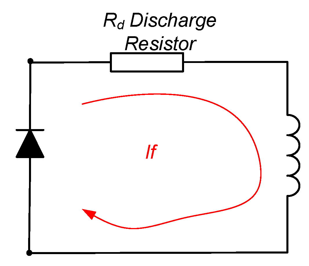
Figure 7.
AVR brushless excitation system with additional static field breaker (SFB). Exciter field current in case of transient de-excitation (field breaker closed SFB open).
Figure 7.
AVR brushless excitation system with additional static field breaker (SFB). Exciter field current in case of transient de-excitation (field breaker closed SFB open).

Figure 8.
Simulation model of the brushless SFB de-excitation of a 40 MVA synchronous generator.

Figure 9.
De-excitation at rated voltage simulation results at no-load, for 40 MVA synchronous generator. Stator voltage.
Figure 9.
De-excitation at rated voltage simulation results at no-load, for 40 MVA synchronous generator. Stator voltage.

Figure 10.
De-excitation at rated voltage simulation results at no-load, for 40 MVA synchronous generator. Rotor voltage.
Figure 10.
De-excitation at rated voltage simulation results at no-load, for 40 MVA synchronous generator. Rotor voltage.

Figure 11.
De-excitation at rated voltage simulation results at no-load, for 40 MVA synchronous generator. Excitation voltage.
Figure 11.
De-excitation at rated voltage simulation results at no-load, for 40 MVA synchronous generator. Excitation voltage.

Figure 12.
Step-down voltage setpoint simulation results at no-load for 40 MVA synchronous generator. Stator voltage.
Figure 12.
Step-down voltage setpoint simulation results at no-load for 40 MVA synchronous generator. Stator voltage.

Figure 13.
Step-down voltage setpoint simulation results at no-load for 40 MVA synchronous generator. Rotor voltage.
Figure 13.
Step-down voltage setpoint simulation results at no-load for 40 MVA synchronous generator. Rotor voltage.

Figure 14.
Step-down voltage setpoint simulation results at no-load for 40 MVA synchronous generator. Excitation voltage.
Figure 14.
Step-down voltage setpoint simulation results at no-load for 40 MVA synchronous generator. Excitation voltage.

Figure 15.
Experimental setup 15 MVA, 13 kV synchronous machine for HSBDS + SFB testing.

Figure 16.
Simplified diagram of the 15 MVA, 13 kV experimental setup for HSBDS + SFB testing.

Figure 17.
Experimental setup for HSBDS + SFB testing. (a) External static field breaker controller based on Arduino® (b) Static field breaker (c) HSBDS components mounted in the rotor.
Figure 17.
Experimental setup for HSBDS + SFB testing. (a) External static field breaker controller based on Arduino® (b) Static field breaker (c) HSBDS components mounted in the rotor.

Figure 18.
De-excitation at rated voltage tests results at no-load for 15 MVA synchronous generator. Stator voltage.
Figure 18.
De-excitation at rated voltage tests results at no-load for 15 MVA synchronous generator. Stator voltage.

Figure 19.
Step-down voltage setpoint tests results at no-load for 15 MVA synchronous generator. Stator voltage.
Figure 19.
Step-down voltage setpoint tests results at no-load for 15 MVA synchronous generator. Stator voltage.

Figure 20.
Step-down voltage setpoint tests record. CH1: Diodes bridge voltage; CH2: Discharge resistor voltage; CH3: AVR output voltage; CH4: Control signal to the SFB.
Figure 20.
Step-down voltage setpoint tests record. CH1: Diodes bridge voltage; CH2: Discharge resistor voltage; CH3: AVR output voltage; CH4: Control signal to the SFB.

© 2019 by the authors. Licensee MDPI, Basel, Switzerland. This article is an open access article distributed under the terms and conditions of the Creative Commons Attribution (CC BY) license (http://creativecommons.org/licenses/by/4.0/).
Share and Cite
MDPI and ACS Style
Rebollo, E.; Platero, C.A.; Talavera, D.; Granizo, R. Use of Discharge Resistor to Improve Transient De-Excitation in Brushless Synchronous Machines. Energies 2019, 12, 2528. https://doi.org/10.3390/en12132528
AMA Style
Rebollo E, Platero CA, Talavera D, Granizo R. Use of Discharge Resistor to Improve Transient De-Excitation in Brushless Synchronous Machines. Energies. 2019; 12(13):2528. https://doi.org/10.3390/en12132528
Chicago/Turabian StyleRebollo, Emilio, Carlos A. Platero, David Talavera, and Ricardo Granizo. 2019. "Use of Discharge Resistor to Improve Transient De-Excitation in Brushless Synchronous Machines" Energies 12, no. 13: 2528. https://doi.org/10.3390/en12132528
Note that from the first issue of 2016, this journal uses article numbers instead of page numbers. See further details here.