Design and Analysis of a Novel Converter Topology for Photovoltaic Pumps Based on Switched Reluctance Motor
by
Xiaoshu Zan
1, 
Ning Wu
1,*,
Ruidong Xu
1,
Mingliang Cui
1,
Zhikai Jiang
1,
Kai Ni
2 and
Mohammed Alkahtani
2 1
School of Electrical and Power Engineering, China University of Mining and Technology, Xuzhou 221116, China
2
Department of Electrical Engineering and Electronics, University of Liverpool, Liverpool L69 3GJ, UK
*
Author to whom correspondence should be addressed.
Energies 2019, 12(13), 2526; https://doi.org/10.3390/en12132526
Submission received: 25 May 2019
/
Revised: 26 June 2019
/
Accepted: 27 June 2019
/
Published: 1 July 2019
Abstract
:In order to improve the performance of switched reluctance motor (SRM) systems for photovoltaic (PV) pumps, this paper introduces a new converter topology for SRM with controllable multiple power sources. Only simple switching components need to be added at the front end of the asymmetric half-bridge converter in this topology, which enables the control of multiple power sources. The new PV pump system has four operating modes, which are the PV panel driven mode, battery bank driven mode, dual-source driven mode, and battery charging mode. By adjusting the state of the front-end converter switch, the voltage tracking of PV panel can be achieved, providing a stable bus voltage for the SRM system. By controlling the battery bypass switch, the bus voltage of SRM system can be increased, thereby increasing the system power level. Simulations and experiments based on a four-phase 8/6 SRM demonstrate the effect of the novel converter proposed in this paper.
1. Introduction
Economic growth is typically coupled with the energy consumption, and the energy consumption is linked to the pollutions of the environment. Global warming is one the most important hazards for the Earth’s future and the use of renewable energy sources is a valid solution to stop their adverse influences on human life. In recent years, new clean energy sources have received widespread attention in order to reduce the dependence on fossil fuels, among which the solar energy has received the most attention [1,2,3,4]. Solar energy can play a key role in this energy transition for the global energy supply. It is obvious that PV energy as a new type of renewable energy got great development compared with other energy. China’s PV energy capacity is the largest in the world and plays an important role in the country’s energy economy [1]. With a continuously increasing urban population, the alarming issues of energy security and climate change are becoming more prominent than ever, requiring careful planning and effective measures. Solar PV is one of the most promising forms of renewable energy production. Fast technological improvements, cost reduction and public acceptance are the key factors that accelerate the global demand for solar systems. Besides, the solar system is noiseless, pollution-free, and can generate electricity on the spot without consuming fuel or setting up transmission lines. A strategic advantage of solar motors is the modular nature of the technology, which makes it ideal for onsite energy production and consumption, leading to a critical reduction in transformation and transmission losses [2].
As an effective solution to air pollution and energy shortage, solar photovoltaic (PV), which is one of the most promising forms of renewable energy production, is applied in residential, aerospace, vehicle, and pump system applications. Unlike diesel pumps, PV pumps are clean alternatives, especially in the central and western water-scarce areas of China, where PV pumps play a more significant role. A PV pump system consists of PV panels, motors, and pumps. In addition, battery banks can be selectively installed in the PV pump system as energy storage devices. The PV pump system with battery banks can store solar energy to ensure the system can work on cloudy days and at night. In the current design of the PV pump system, the motor is driven by an inverter, whose DC bus is connected to a PV panel or battery bank. The battery bank is charged by the PV panel through a DC converter. Due to the complicated control of the system, the switching tube in the converter requires a high withstand voltage, there is a high risk of loss of control and damage.
The PV pump system uses a switched reluctance motor (SRM) as the motor. The traditional SRM control system for PV pumps uses a single power supply [5,6,7]. A PV-sourced SRM system based on MPPT control is proposed [5]. This system can switch among four operation modes, using only one power converter. The bus voltage is limited by the power supply. Therefore, the excitation voltage and freewheeling voltage of the motor are limited by the bus voltage. To solve this problem, some boost converters are proposed [8,9,10,11,12,13]. The typical boost converter configuration is presented [8], the freewheeling current is absorbed by the additional capacitor and used to increase the excitation voltage during the next phase excitation state. However, the voltage boosted by the converter is related to the commutation frequency. In order to keep the voltage value stable, the boost voltage working area must be balanced by the load. In addition, as the winding inductance increases, the boost voltage gradually decreases. This is not conductive to the establishment of the excitation current at high speed. A new hybrid asymmetric and buck-boost fronted converter are used as the SRM’s drivers to improve performance of SRM at high speed [9]. This proposed converter has an active regulation ability of boosting voltage, in which voltage level is independent from switching and dwell angels. However, the boost voltage of the converter gradually decreases as the inductance increases. A structure, hybrid of Zeta and Landsman converters, of single switch dual-output DC-to-DC converter is proposed for PV power to reduce the cost [10]. However, the instability is increased because of the complex combination. The proposed converter is composed of two standard six-pack switch modules [11]. In spite of the stronger fault-tolerance ability, the higher cost limits the application. A novel converter with one power switch per phase is proposed [12]. The number of power switches is half of asymmetric half bridge converter. However, the fault tolerance ability is not as good as asymmetric half bridge converter. An improved asymmetric half bridge converter is presented and investigated [13]. The dynamic performance, such as average torque, torque density and output power, is better than the conventional converter. However, the additional components result in higher cost. The dragonfly algorithm of switched reluctance motor is introduced to anticipate optimal operations of autonomous stacked proton membrane fuel cells serving a switched reluctance motor [14]. The emphasis is dragonfly algorithm with six controlling parameters, e.g., fuel cell temperature, air flow rate, air pressure, fuel pressure, and turn on/off angles of switched reluctance motor. A new permanent magnet RotLin motor, which is able to realize high-precision control both in the linear and the rotary directions, is introduced [15]. The motor structure and operation principles are introduced, followed by a detailed design procedure both on the linear part and the rotary part of the motor. Magnetic circuit analysis confirms the feasibility of the simple structure of the motor. The FEM resulted has verified linear force outputs and rotational torque outputs simultaneously. This paper focuses on designing the main converter of the PV pump system. On the basis of the traditional switched reluctance motor converter topology, a small number of power devices and an added battery pack are added to improve the output power of the PV pump system and increase the output torque of the SRM motor.
In order to prolong the boosting working area time and keep the voltage values stable throughout the boosting region, this paper proposes a new converter topology. Different from the existing booster-capable converters, the converter proposed in this paper can guarantee the stability of boosting in both the low speed and high speed ranges. Because the bus voltage of the freewheeling phase is increased, the freewheeling time can be effectively reduced. Moreover, the freewheeling current is rapidly decreased, and it is prevented from appearing in the inductor falling region to generate a negative torque.
This paper is organized in the following structure. Section 2 presents the conventional SRM drive system. Section 3 proposes a new converter for PV pump system; the driving mode and charging mode are investigated; the current flow and phase voltage are analyzed. The proposed drive topology is verified by simulation and experiments in Section 4. Finally, the conclusion is given in Section 5.
2. Analysis of the Proposed SRM Drives
2.1. Convertional SRM Drives
An SRM is a doubly salient variable reluctance motor, and the salient poles of the rotor are laminated with ordinary steel sheets [16,17,18,19,20,21,22,23,24,25,26,27]. The structure of the SRM is shown in Figure 1. Here, the phase-A is taken as an example to illustrate its working principle. When the rotor of the SRM is in the position, as shown in Figure 1, switches S1 and S2 are turned on to excite phase-A to form the S1-A-A*-S2 loop, the phase-A excitation current flow diagram is shown in Figure 2a. Once S1 and S2 are turned off, the energy stored in the phase-A winding is fed back to the DC power supply through the freewheeling diode, the phase-A freewheeling current flow diagram is shown in Figure 2b. The phase-A current waveform is shown in Figure 3.
The asymmetric half-bridge circuit is shown in Figure 4, where each bridge arm is operated by two switches. Besides, each phase of winding is independent of the others, thus providing good fault tolerance. In order to reduce the loss of energy, the soft chopping control mode is usually used to control the speed of SRM.
The asymmetric half-bridge circuit is shown in Figure 4, where each bridge arm is operated by two switches. Besides, each phase winding is independent of the others, thus providing good fault tolerance. In order to reduce the loss of energy, the soft chopping control mode is usually used to control the speed of SRM.
As for conventional SRM drives, the constant DC-bus voltage makes it impossible to achieve the multilevel voltage. Thus the output torque and the range of speed are limited. Besides, the limited output power caused by fixed bus voltage, the small torque caused by insufficient excitation current during the excitation state and the risk of negative torque because of the inability to achieve rapid demagnetization during the demagnetization state are also the inherent disadvantages and limitations. Multisource operation and flexible charging functions cannot be achieved because there is only one source connected to the converter circuit. The proposed converter, which will be analyzed in detail in the next section, can improve the motor system performance and achieve flexible charging functions.
2.2. Proposed Converter Topology
The new topology proposed in this paper adds a battery bank control converter and a PV panel boost converter based on the traditional asymmetric half-bridge converter, as shown in Figure 5. The voltage boosting function of the PV panel can be realized by controlling the on and off states of S1. Additionally, controlling the on and off states of S2 can realize multilevel control of the asymmetric half-bridge bus voltage. During the freewheeling state, the energy stored in the inductor can be fed back into the battery bank and capacitor C1 through the diode. It is easy to switch among the four modes by controlling the on and off states of S1 and S2 with the proposed converter.
2.3. Operating Modes
According to different driving sources, the operating modes can be categorized as the PV driven mode, battery bank driven mode and dual-source driven mode.
Mode 1: Driven by the PV.
S2 is turned off and S1 is turned on. The SRM is driven by the single PV panel during the excitation state, and the power stored on the windings is fed back to the front-end capacitor and battery bank during the demagnetization state. Because of the presence of battery bank, the bus voltage rises during the demagnetization process and the demagnetization time is reduced, which realizes fast demagnetization. The phase voltage and current waveforms are shown in Figure 6b.
Mode 2: Driven by the battery bank.
S1 is turned off and S2 is turned on. The SRM is driven by the single battery bank during the excitation state, and the power stored on the windings is fed back to the front-end capacitor and battery bank during the demagnetization state. Because the initial voltage of the capacitor is zero, the phase voltage and current waveforms are shown in Figure 6c.
Mode 3: Driven by the dual-source.
S1 and S2 are both turned on. The SRM is driven by both the PV panel and battery bank during the excitation state, and the energy stored on the windings is fed back to the front-end capacitor and battery bank during the demagnetization state. It also can realize fast demagnetization. Because the bus voltage increases, the SRM has a wider speed range and higher torque. The phase voltage and current waveforms are shown in Figure 6d.
2.4. Driven by the PV Panel
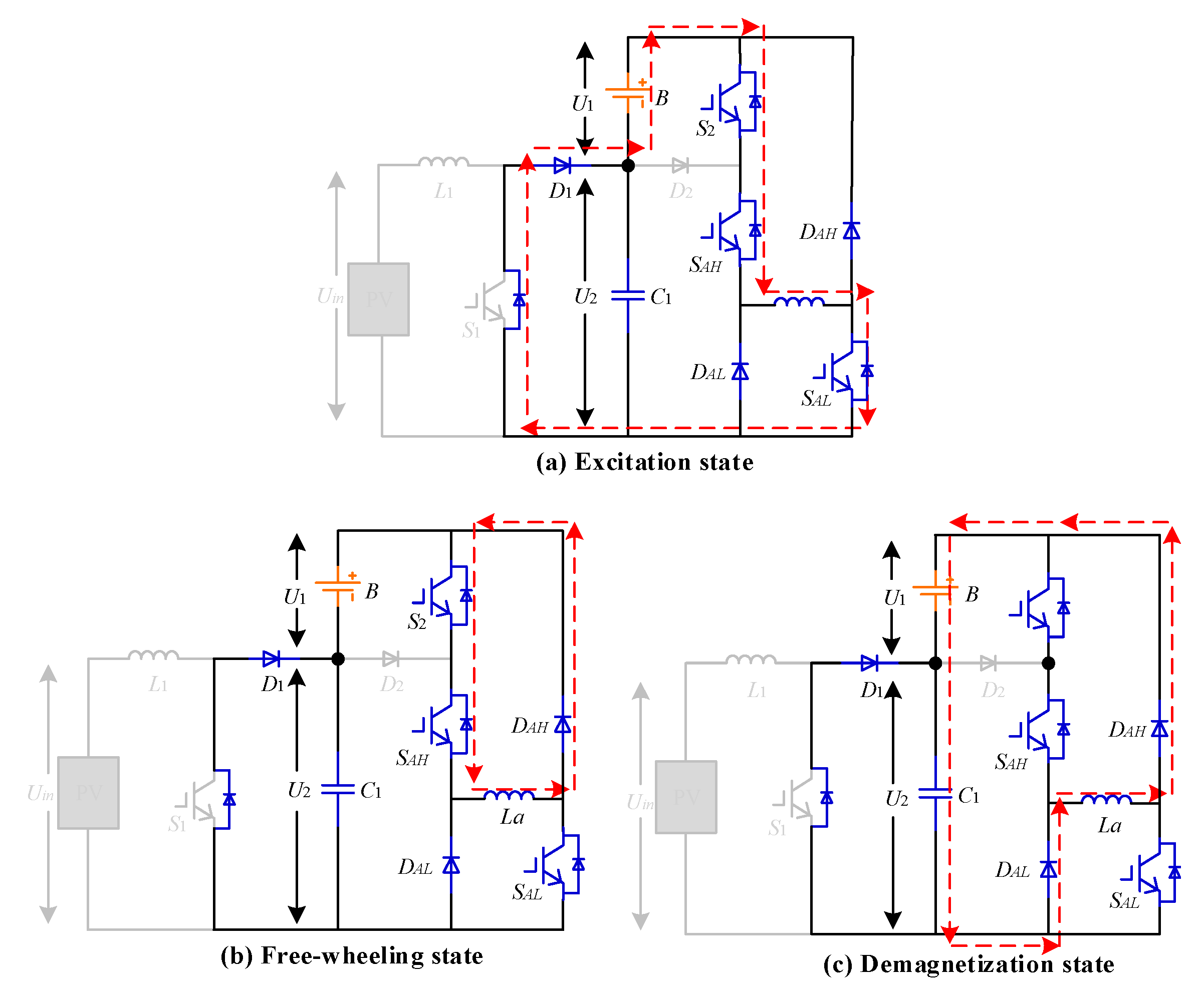
In mode 1, the system has three working states, including the excitation state, freewheeling state and demagnetization state. The energy flow diagram for each working state is shown in Figure 7.
Regardless of the voltage losses of the IGBT and diode, the phase voltage can be expressed as
where U2, Ra, ia, La, θr, φ(ia, θr), and ωr are the voltage across the capacitor, phase-A winding internal resistance, phase-A winding current, phase-A winding inductance, motor position, flux linkage, and motor angular velocity, respectively.
During the excitation state, the switches SAH and SAL are turned on, as shown in Figure 7a. The voltage of phase-A is equal to that of capacitor C, which is expressed as
During the freewheeling state, the energy stored in the phase-A winding is fed back to the battery, as shown in Figure 7b. The voltage of phase-A is equal to that of the battery bank, which is expressed as
During the demagnetization state, the energy stored in the phase-A winding is fed back to the capacitor C and battery bank, as shown in Figure 7c. The voltage of phase-A is equal to the sum of those on the capacitor and battery, which is expressed as
2.5. Driven by the Battery Bank
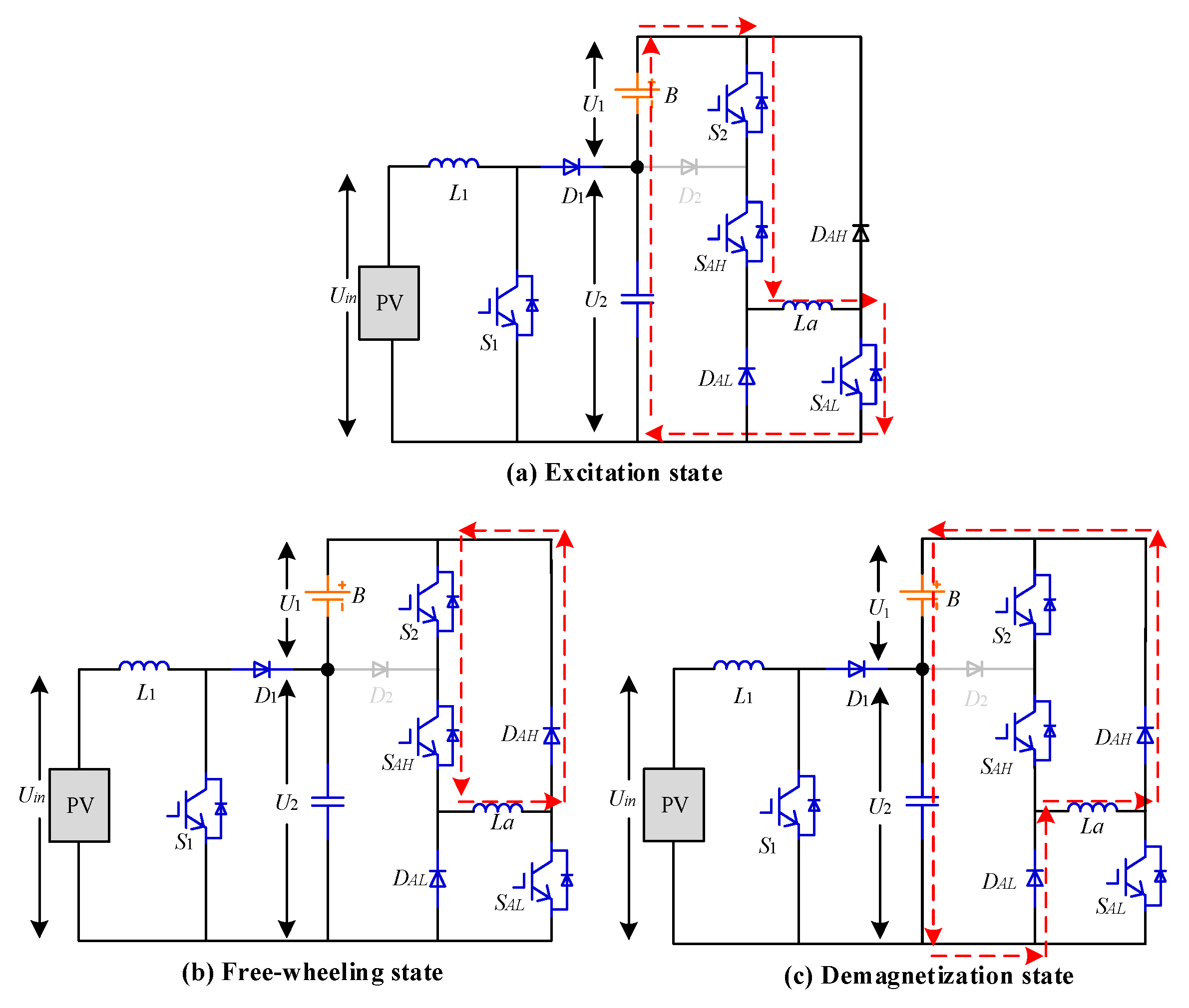
In mode 2, the system has three working states: the excitation state, freewheeling state, and demagnetization state. The energy flow diagram for each working state is shown in the Figure 8.
During the excitation state, the switches SAH and SAL are turned on, as shown in Figure 8a. The voltage of phase-A is equal to that of the battery bank, which is expressed as
where U1, Ra, ia, La, θr, and ωr are the voltage of the battery bank, phase-A winding internal resistance, phase-A winding current, phase-A winding inductance, motor position, and motor angular velocity, respectively.
During the freewheeling state, the phase-A winding forms a loop with the diode and the switches, as shown in Figure 8b. The voltage of phase-A is zero, which is expressed as
During the demagnetization state, the energy stored in the phase-A winding is fed back to the capacitor C and battery bank, as shown in Figure 8c. Because the initial voltage on the capacitor is zero, the voltage of phase-A is equal to that of battery bank, which is expressed as
2.6. Driven by the Dual-sources
In mode 3, the system has three working states, including the excitation state, freewheeling state and demagnetization state. The energy flow diagram for each working state is shown in the Figure 9.
During the excitation state, the switches SAH and SAL are turned on, as shown in Figure 9a. The voltage of phase-A is equal to the sum of those on the capacitor and battery bank, which is expressed as
where U1, Ra, ia, La, θr, and ωr are the voltage of the battery bank, phase-A winding internal resistance, phase-A winding current, phase-A winding inductance, motor position, and motor angular velocity, respectively.
During the freewheeling state, the phase-A winding forms a loop with the diode and the switches, as shown in Figure 9b. the voltage of phase-A is zero, which is expressed as
During the demagnetization state, the energy stored in the phase-A winding is fed back to the capacitor C and battery bank, as shown in Figure 9c. The voltage of phase-A is equal to the sum of those on the capacitor and battery, which is expressed as
2.7. Charging Mode
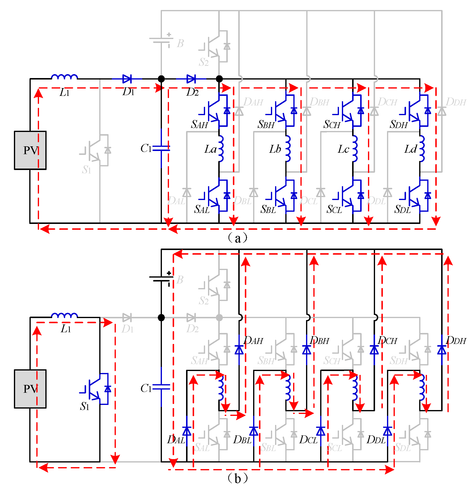
In the static state of the SRM, the battery can be charged by the PV panel by controlling S1 and the eight switches on the asymmetric half-bridge.
In this mode, the system can operate in two states, as shown in Figure 10. During state 1, S1 is turned off and SAH–SDL are turned on. At this point, the PV panel and electrical energy stored in the inductor are superimposed to power the four-phase winding. During state 2, S1 is turned on and SAH–SDL are turned off. At this point, the four-phase winding fed back the energy stored in the winding to the battery bank and capacitor through the diode. In this mode, the charge current of the battery bank can be flexibly controlled by controlling the duty cycles of the switches.
In working state 1, the phase-A current is
where , Iai, T, and D are the maximum phase-A current, initial phase-A current, switching period and duty cycle.
In working state 2, the phase-A current can be expressed as
By controlling the four-phase windings, the maximum and minimum currents can be shown as
Thus, in working state 2, the battery charging current is expressed as
2.8. Control Schemes for SRM Drives
In the voltage chopping control mode, the chopping switch of a phase branch is turned on and off at a set frequency, and the duty cycle D is given by
where ton and toff are the turn-on and turn-off time periods of PWM in one cycle, respectively.
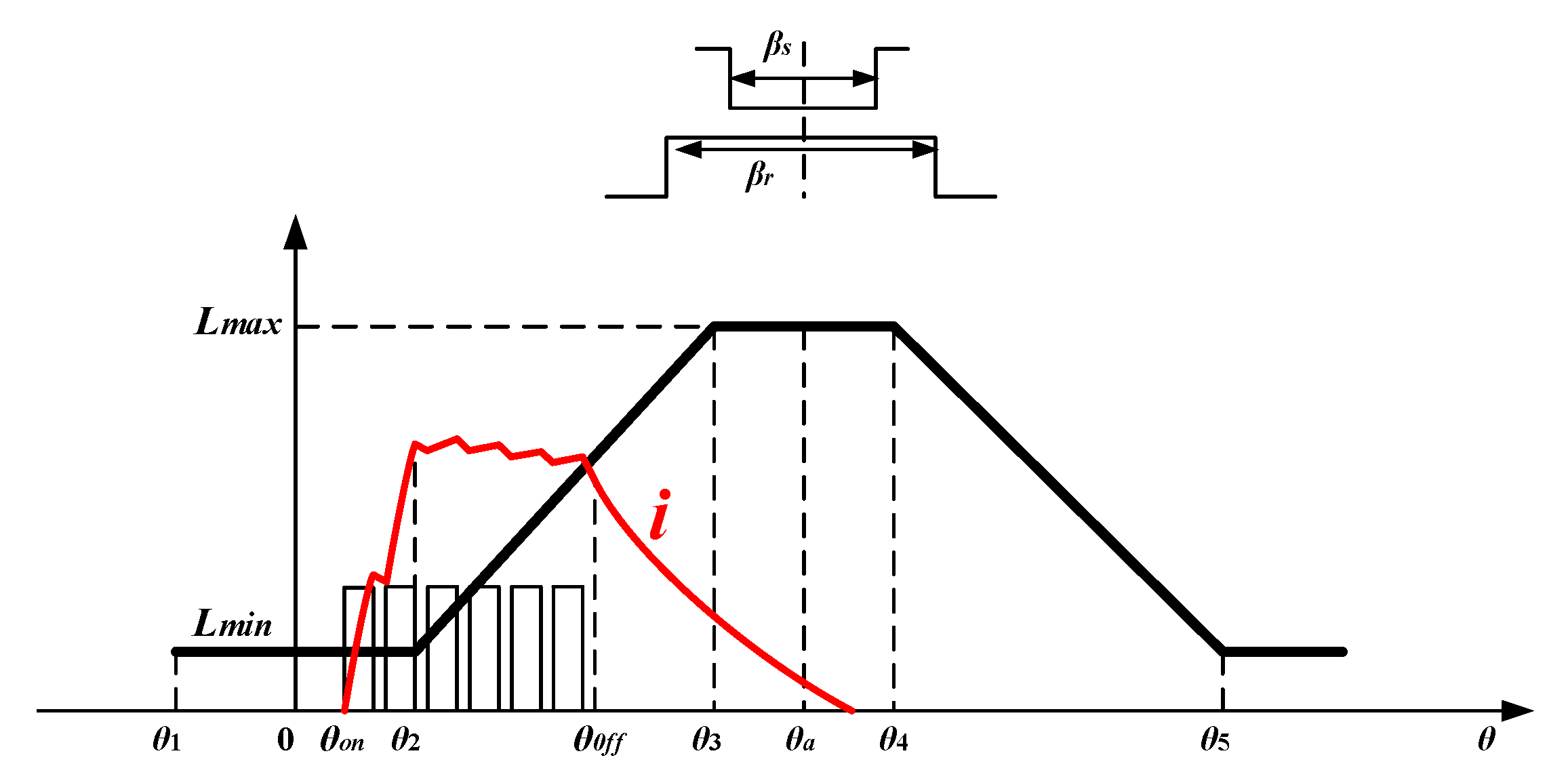
The voltage chopping waveform with soft chopping control is shown in Figure 11. In the voltage chopping control mode, S1 maintains the conduction state during the whole phase-A conduction, and S2 adopts the PWM chopper control. When S2 is turned on, the voltage Udc is applied to both ends of the phase-A winding and the voltage across phase-A is the bus voltage; when S2 is turned off, the phase-A winding forms the circulating current through S1 and D1 and the voltage across the phase-A winding is zero. The average voltage applied to the phase-A is DUdc.
The voltage chopping control and angular position control are two basic control schemes. Different control methods are adopted according to the set speed, where the voltage chopping control scheme is adopted at low speed and the angular position control scheme is adopted at full speed. As shown in Figure 12, the motor speed is calculated by the encoder. In the voltage chopping control mode, the speed error is processed by the PI controller to adjust the rotational speed of the SRM. In the angular position control mode, the opening and closing angles vary as the error of the speed, so as to change the excitation freewheeling time of the winding.
2.9. Limitations and Applications
The proposed converter is used to drive switched reluctance motors. Compared with the traditional drive topology, the bus voltage is higher, so the voltage range of the power devices that can withstood needs to be considered in the design. It is very convenient to install the PV pump system in some area where the climate is very dry. Switched reluctance motor, which is simple to maintain because of the low cost, is more suitable for the dusty area. Therefore, the system has a great market in these areas. Connecting photovoltaic panels, battery packs and switched reluctance motors to the novel converter proposed in this paper, the system driven by PV, battery pack or the dual-source combination can be achieved. Although this paper has targeted PV pump applications, the novel converter can also be applied to other applications such as electrified vehicle and electrical ships.
3. Simulation Results
In order to confirm the feasibility of the proposed converter topology, a low-power four-phase 8/6-pole prototype SRM is employed for proof-of-concept. The SRM parameters are given in Table 1.
The simulation model of the SRM drive system is established in MATLAB/Simulink. The Flux linkage of the SRM is shown in Figure 13.
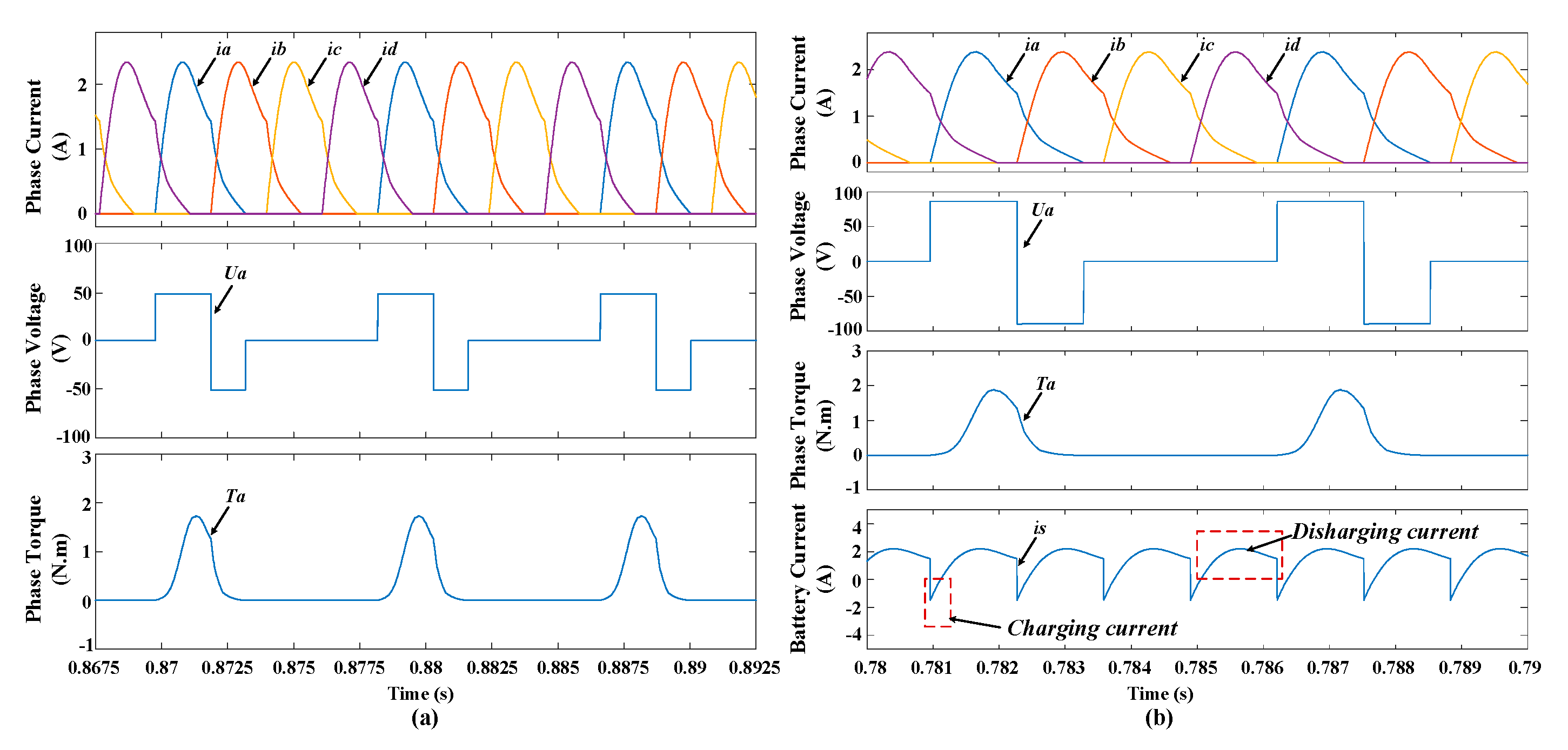
In the simulations, the PV panel voltage and battery voltage are given as 25 V and 36 V, respectively; the load is given as 1N·m; and the duty cycle and frequency of S1 are given as 50% and 2 kHz, respectively, so the voltage of U2 is 50V. In the simulation waveforms, ia, ib, ic, and id are the phase-A, phase-B, phase-C, and phase-D currents, respectively, Ua is the phase-A voltage, Ta is the phase-A torque, and is is the battery current.
The waveforms of the phase currents, phase voltage, phase torque and battery current are shown in Figure 14, while the speed is 600 rpm. Figure 14a gives the phase voltage and phase current with the conventional converter. The phase-A voltage switches between +50 and –50 V due to the changes of switching states. In the proposed drive, S2 is OFF, and S1 duty cycle is set as 50%. The motor operates in the single power mode, whose source is a PV panel. As illustrated in Figure 14b, the battery bank is employed to boost the phase voltage in the demagnetization mode. The battery bank is charged during the demagnetization state and freewheeling state due to the inherent features of the proposed converter. When the PV panel is idle, the drive works in the single battery power mode, as shown in Figure 14c, where S2 is on while S1 is off. The phase-A voltage changes between +36 and –36 V with the changes of switching states. The battery is charged during the demagnetization state. Figure 14d shows the simulation results when the converter works in the dual-source driving mode when S2 is ON and S1 duty cycle is 50%. In this mode, because of the additional battery bank, the fast excitation and fast demagnetization are also both achieved. Besides, the output torque and power are improved.
Figure 15 illustrates the simulation waveforms when the motor runs at full speed. When the conventional converter is applied, the speed of SRM can reach 1200 rpm in full speed operation, while it can reach 2000 rpm in the dual-source mode. Therefore, the range of speed is wide accordingly due to the novel converter because of the higher bus voltage. In the dual-source mode, the battery bank is charged and discharged repeatedly.
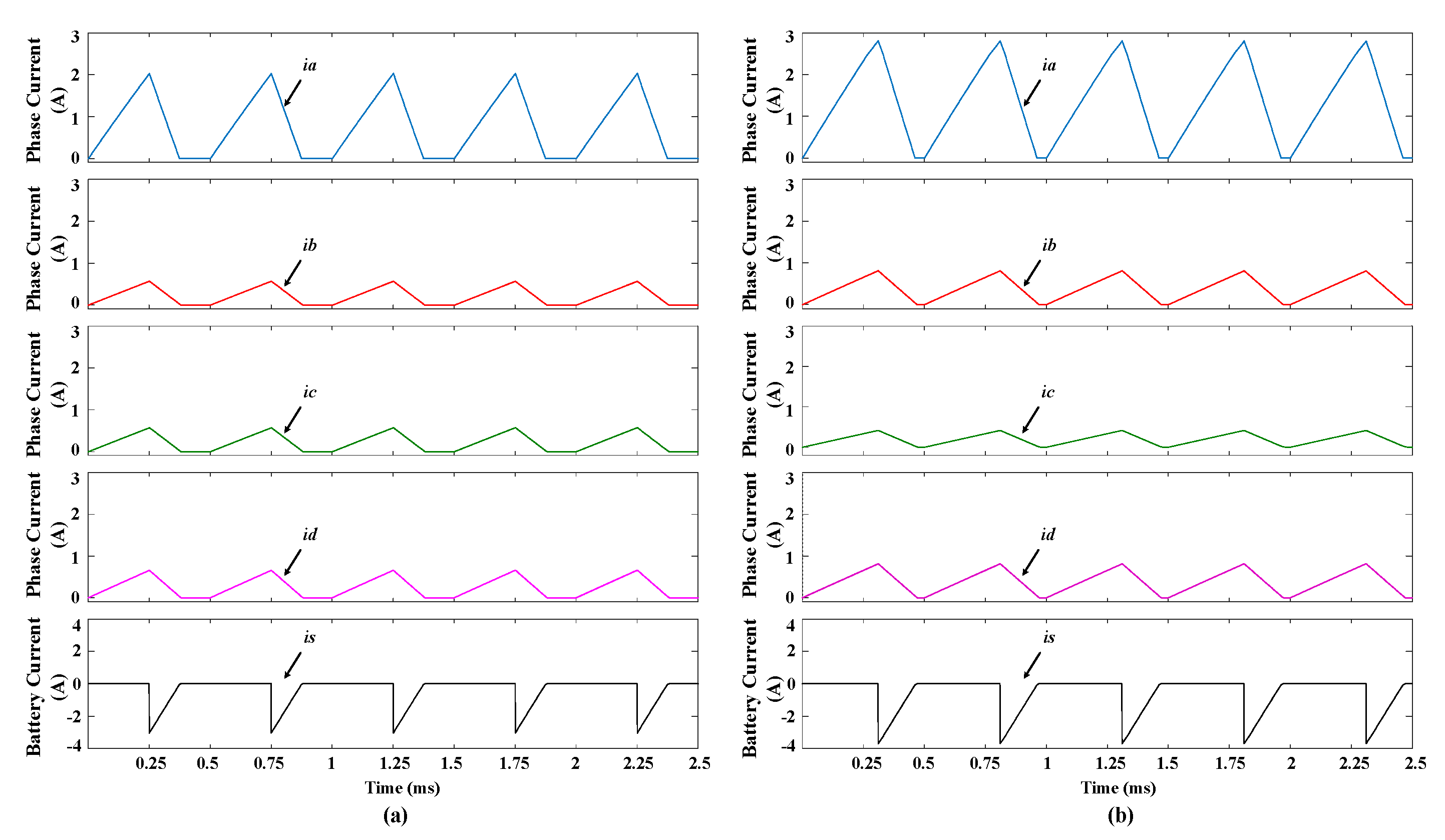
When the motor is in the stationary state, the battery charging process can be flexibly achieved by the PV panel through motor windings. The waveforms of battery charging in this state is illustrated in Figure 16, where the switching frequency is given as 2 kHz and the duty is given as 50% in Figure 16a and 60% in Figure 16b. When S2 is off while SAH~SDL are on, the four-phase windings are simultaneously energized by the PV panel and the electrical energy stored in the inductor, and the phase currents rise until SAH–SDL are turned OFF. Afterwards, the battery bank is charged by the power stored in the phase windings. In conclusion, because of the additional battery bank and the higher bus voltage, the battery can be flexibly charged by the external PV panel. Besides, the charging current is related to the energy stored in the four phase windings.
The higher bus voltage, which is boosted by the battery bank installed on the upper arm of the asymmetric half-bridge circuit, can make the excitation and demagnetization faster. Besides, the output torque and power are improved, the speed range is wider and the battery can be flexibly charged.
4. Experimental Results
In order to demonstrate the effect of the converter, the simulation of a 500 W SRM is established with the same parameters. The experimental platform is shown in Figure 17. The novel converter, which is established with the IGBT using a fast recovery antiparallel diode inside, drives the motor. The PV panel power is simulated by the 50 V DC power which can be adjusted. In addition, three 12 V-batteries are connected in series to form a 36 V battery bank. In addition, the rotor position is determined through a 1000-line incremental encoder. The main control system is implemented by TMS320F28335 digital signal processor made by Texas Instruments. The Hall effect current sensors are employed to collected the waveforms of phase currents.
Figure 18 illustrates the experimental waveforms at 600 rpm and 1N·m load, where ia is the phase-A current, is the phase-A voltage, and is is the battery current. Figure 18a–d shows the experimental waveforms when the SRM is driven by a conventional converter, PV panel, battery bank and dual-source, respectively. According to the waveforms in Figure 18, the time of demagnetization state is reduced compared with the conventional converter. The output torque of the motor is increased in the novel converter. Figure 19 shows the experimental waveforms at full speed operation, and the speed of SRM can reach 1200 rpm in this operation mode. In comparison, the speed of SRM can reach 2000 rpm in the dual-source mode. Therefore, the output torque of the motor is increased in the novel converter due to the higher bus voltage.
Figure 20 illustrates the current waveforms when the motor is in stationary state. The switching frequency is set to 2 kHz and duty cycle is given as 50% and 60% in Figure 20a,b, respectively. All the switches are turned on simultaneously to charge the four-phase windings. Afterwards, the battery bank is charged by the energy of the phase windings while the switches are turned off simultaneously. In conclusion, because of the additional battery bank and the higher bus voltage, the battery can be flexibly charged by the external PV panel and the charging current is related to the energy stored in the four phase windings.
5. Conclusions
In this paper, a novel converter, which not only improves the motor system performance in running conditions, but also achieves flexible charging functions, is proposed for SRM motor drive system. Its operating principle is deeply investigated by the analysis of different modes. Compared with a conventional converter such as asymmetric converter, it improves the output torque and power by faster current building-up and rapid demagnetization. Compared to the existing PV pump system, the novel converter, which can be used for multilevel voltage and multimode operations, is provided with fewer electronic components, simpler control strategies, and higher power density. Besides, the battery bank is installed on the upper arm of the asymmetric half-bridge circuit to boost bus voltage and absorb energy during demagnetization state. The simulation and experimental results prove that the novel converter is more suitable for SRM with the wider range of speed and the higher output torque. And the multimode operations proposed in the paper can work stably and safely. The main contributions and advantages of this paper are as follows.
(1) The voltage of DC-bus can be boosted by employing additional battery bank, thus the torque capability and power can be improved.
(2) Multiple modes of operation can be realized by controlling the state of the front-end switch devices, ensuring that the photovoltaic pump system operates in various environments.
(3) A variety of charging functions such as running charging and stationary charging are implemented. With the demagnetization current, the battery is charged in the operating state and the braking state, respectively. In the standstill state, the battery can also be charged from the PV via the proposed driver.
Author Contributions
X.Z. and R.X. Provided theoretical guidance of the method; N.W. wrote the original draft manuscript; M.C. and Z.J. provided the literature analysis for the review article; K.N. and M.A. reviewed and edited the paper manuscript.
Funding
This research is supported by “The Fundamental Research Funds for the Central Universities” with No 2019GF06.
Conflicts of Interest
The authors declare no conflict of interest.
References
- D’Adamo, I. The Profitability of Residential Photovoltaic Systems. A New Scheme of Subsidies Based on the Price of CO2 in a Developed PV Market. Soc. Sci. 2018, 7, 148. [Google Scholar] [CrossRef]
- Moraitis, P.; Kausika, B.B.; Nortier, N.; Van Sark, W. Urban Environment and Solar PV Performance: The Case of the Netherlands. Energies 2018, 11, 1333. [Google Scholar] [CrossRef]
- Quéval, L.; Coty, A.; Vido, L.; Gottkehaskamp, R.; Multon, B. A Switched Reluctance Motor Drive Using Photovoltaic Transistors: Principle, Prototype, Experimental, and Numerical Results. IEEE Trans. Ind. Appl. 2017, 53, 4886–4893. [Google Scholar] [CrossRef] [Green Version]
- Belliwali, S.; Chakravarti, A.; Raju, A.B. Mathematical modelling and simulation of directly coupled PV water pumping system employing Switched Reluctance Motor. In Proceedings of the ISGT2011-India, Kollam, Kerala, India, 1–3 December 2011. [Google Scholar]
- Wang, X.; Gan, C.; Hu, Y.; Cao, W.; Chen, X. Renewable energy-fed switched reluctance motor for PV pump applications. In Proceedings of the 2014 IEEE Conference and Expo Transportation Electrification Asia-Pacific (ITEC Asia-Pacific), Beijing, China, 31 August–3 September 2014. [Google Scholar]
- Indragandhi, V.; Selvamathi, R.; Arunkumari, T. Speed control of a switched reluctance motor using PID controller for PV based water pumping applications. In Proceedings of the 2017 Innovations in Power and Advanced Computing Technologies (i-PACT), Vellore, India, 21–22 April 2017. [Google Scholar]
- Mishra, A.K.; Singh, B. Design of PV powered SR motor driven irrigation pumps utilizing boost converter. In Proceedings of the 2016 IEEE Uttar Pradesh Section International Conference on Electrical, Computer and Electronics Engineering (UPCON), Varanasi, India, 9–11 December 2016. [Google Scholar]
- Peng, C.; Song, S.; Ma, R.; Liu, W. A novel modular 4-level power converter-based direct instantaneous torque control strategy for switched reluctance machine. In Proceedings of the 13th IEEE Conference on Industrial Electronics and Applications (ICIEA), Wuhan, China, 31 May–2 June 2018. [Google Scholar]
- Qu, Z.; Wang, H.; Tang, S.; Wei, X.; Chen, Q. A new hybrid asymmetric and buck-boost fronted converter for SRM with active boost voltage capability. In Proceedings of the 20th International Conference on Electrical Machines and Systems (ICEMS), Sydney, NSW, Australia, 11–14 August 2017. [Google Scholar]
- Mishra, A.K.; Singh, B. Design of solar-powered agriculture pump using new configuration of dual-output buck–boost converter. IET 2018, 12, 1640–1650. [Google Scholar] [CrossRef]
- Sun, Q.; Wu, J.; Gan, C.; Guo, J. Modular Full-Bridge Converter for Three-Phase Switched Reluctance Motors with Integrated Fault-Tolerance Capability. IEEE Trans Power Electron. 2019, 34, 2622–2634. [Google Scholar] [CrossRef]
- Hu, Y.; Wang, T.; Ding, W. Performance Evaluation on a Novel Power Converter with Minimum Number of Switches for a Six-Phase Switched Reluctance Motor. IEEE Trans Power Electron. 2019, 66, 1693–1702. [Google Scholar] [CrossRef]
- Ding, W.; Yang, S.; Hu, Y. Performance Improvement for Segmented-Stator Hybrid-Excitation SRM Drives Using an Improved Asymmetric Half-Bridge Converter. IEEE Trans. Ind. Electron. 2019, 66, 898–909. [Google Scholar] [CrossRef]
- El-Hay, E.A.; El-Hameed, M.A.; El-Fergany, A.A. Performance enhancement of autonomous system comprising proton exchange membrane fuel cells and switched reluctance motor. Energy 2018, 163, 699–711. [Google Scholar] [CrossRef]
- Zou, Y.; Wai, K.; Cheng, E. Design and Control of a Permanent Magnet RotLin Motor for New Foldable Photovoltaic Units. Energies 2019, 12, 1983. [Google Scholar] [CrossRef]
- Gan, C.; Sun, Q.; Wu, J.; Kong, W.; Shi, C.; Hu, Y. MMC-Based SRM Drives with Decentralized Battery Energy Storage System for Hybrid Electric Vehicles. IEEE Trans. Power Electron. 2019, 34, 2608–2621. [Google Scholar] [CrossRef]
- Gan, C.; Wu, J.; Shen, M.; Yang, S.; Hu, Y.; Cao, W. Investigation of Skewing Effects on the Vibration Reduction of Three-Phase Switched Reluctance Motors. IEEE Trans. Magn. 2015, 51, 8203509. [Google Scholar] [CrossRef]
- Chen, H.; Han, G.; Shi, X.; Dong, J. Phase Current Digital Analysis of Power Converter for Freewheeling Diode Fault Diagnosis on Switched Reluctance Motor Drive. IEEE Trans. Ind. Electron. 2019, 66, 6613–6624. [Google Scholar] [CrossRef]
- Husain, T.; Elrayyah, A.; Sozer, Y.; Husain, I. Unified Control for Switched Reluctance Motors for Wide Speed Operation. IEEE Trans. Ind. Electron. 2019, 66, 3401–3411. [Google Scholar] [CrossRef]
- Yan, N.; Cao, X.; Deng, Z. Direct Torque Control for Switched Reluctance Motor to Obtain High Torque–Ampere Ratio. IEEE Trans. Ind. Electron. 2019, 66, 5144–5152. [Google Scholar] [CrossRef]
- Abd Elmutalab, M.; Elrayyah, A.; Husain, T.; Sozer, Y. Extending the Speed Range of a Switched Reluctance Motor Using a Fast Demagnetizing Technique. IEEE Trans. Ind. Appl. 2018, 54, 3294–3304. [Google Scholar] [CrossRef]
- Chen, H.; Zhan, Y.; Nie, R. Multiobjective Optimization Design of Single-Phase Tubular Switched Reluctance Linear Launcher. IEEE Trans. Plasma Sci. 2019, 47, 2431–2437. [Google Scholar] [CrossRef]
- Chen, H.; Xu, S.; Wei, W.; Yang, J.; Nie, R. Reliability Assessment of Double-Sided Linear Switched Reluctance Generator System Based on Hierarchical Markov Model. IEEE Trans. Ind. Electron. 2019, 66, 4901–4911. [Google Scholar] [CrossRef]
- Wei, W.; Wang, Q.; Nie, R. Sensorless control of double-sided linear switched reluctance motor based on simplified flux linkage method. CES Trans. Electr. Mach. Syst. 2017, 1, 246–253. [Google Scholar]
- Chen, H.; Liang, K.; Nie, R.; Liu, X. Three-Dimensional Electromagnetic Analysis of Tubular Permanent Magnet Linear Launcher. IEEE Trans. Appl. Supercond. 2018, 28, 1–8. [Google Scholar] [CrossRef]
- Anand, A.; Singh, B. Modified Dual Output Cuk Converter-Fed Switched Reluctance Motor Drive with Power Factor Correction. IEEE Trans. Power Electron. 2019, 34, 624–635. [Google Scholar] [CrossRef]
- Wang, Q.; Chen, H.; Nie, R. Unbalanced normal force reduction in the eccentric double-sided linear switched reluctance machine. IET Electr. Power Appl. 2016, 10, 384–393. [Google Scholar] [CrossRef]
Figure 1.
Schematic of switched reluctance motor (SRM).

Figure 2.
Operation modes of the asymmetrical half-bridge converter. (a) Excitation state. (b) Demagnetization state.
Figure 2.
Operation modes of the asymmetrical half-bridge converter. (a) Excitation state. (b) Demagnetization state.

Figure 3.
Typical current of phase-A.

Figure 4.
Asymmetric half-bridge converter.

Figure 5.
Proposed converter.

Figure 6.
Phase voltage and current waveforms with the SRM driven by (a) the conventional converter, (b) the PV panel, (c) the battery bank, and (d) the dual-source.
Figure 6.
Phase voltage and current waveforms with the SRM driven by (a) the conventional converter, (b) the PV panel, (c) the battery bank, and (d) the dual-source.

Figure 7.
Working states of mode 1. (a) Excitation state. (b) Free-wheeling state. (c) Demagnetization state.
Figure 7.
Working states of mode 1. (a) Excitation state. (b) Free-wheeling state. (c) Demagnetization state.

Figure 8.
Working states of mode 2. (a) Excitation state. (b) Free-wheeling state. (c) Demagnetization state.
Figure 8.
Working states of mode 2. (a) Excitation state. (b) Free-wheeling state. (c) Demagnetization state.

Figure 9.
Working states of mode 3. (a) Excitation state. (b) Free-wheeling state. (c) Demagnetization state.
Figure 9.
Working states of mode 3. (a) Excitation state. (b) Free-wheeling state. (c) Demagnetization state.

Figure 10.
Working states of the charging mode. (a) Charging state. (b) Discharging state.

Figure 11.
Phase-A current under voltage chopping.

Figure 12.
Control schemes for SRM drives.

Figure 13.
Flux linkage of the SRM.

Figure 14.
Simulation waveforms of 600rpm performance with SRM driven by (a) the conventional converter, (b) the PV panel, (c) the battery bank, and (d) the dual-source.
Figure 14.
Simulation waveforms of 600rpm performance with SRM driven by (a) the conventional converter, (b) the PV panel, (c) the battery bank, and (d) the dual-source.

Figure 15.
Simulation waveforms of full speed performance with SRM driven by (a) the conventional converter (b) the dual-source.
Figure 15.
Simulation waveforms of full speed performance with SRM driven by (a) the conventional converter (b) the dual-source.

Figure 16.
Simulation waveforms of battery charging performance: (a) duty cycle: 50% and (b) duty cycle: 60%.
Figure 16.
Simulation waveforms of battery charging performance: (a) duty cycle: 50% and (b) duty cycle: 60%.

Figure 17.
Experimental platform.

Figure 18.
Experimental waveforms of 600rpm performance with SRM driven by (a) the conventional converter, (b) the PV panel, (c) the battery bank. and (d) the dual-source.
Figure 18.
Experimental waveforms of 600rpm performance with SRM driven by (a) the conventional converter, (b) the PV panel, (c) the battery bank. and (d) the dual-source.

Figure 19.
Experimental waveforms of full-speed performance with SRM driven by (a) the conventional converter and (b) the dual-source.
Figure 19.
Experimental waveforms of full-speed performance with SRM driven by (a) the conventional converter and (b) the dual-source.

Figure 20.
Experimental waveforms of battery charging performance: (a) duty cycle: 50% and (b) duty cycle: 60%.
Figure 20.
Experimental waveforms of battery charging performance: (a) duty cycle: 50% and (b) duty cycle: 60%.


Table 1.
Parameters of SRM.
| Parameters | Value |
|---|---|
| Phase number | 4 8 |
| Stator pole number | |
| Rotor pole number | 6 |
| Rated power (W) | 500 |
| Rated speed (rpm) | 1500 |
| Resistor of phase winding (Ω) | 0.65 |
| Minimum phase inductance (mH) | 10 |
| Maximum phase inductance (mH) | 110 |
| Stator outer diameter (mm) | 116 |
| Stator inner diameter (mm) | 72 |
| Rotor outer diameter (mm) | 70 |
| Rotor inner diameter (mm) | 35 |
| Stator arc angle | 17.5 |
| Rotor arc angle | 23.5 |
© 2019 by the authors. Licensee MDPI, Basel, Switzerland. This article is an open access article distributed under the terms and conditions of the Creative Commons Attribution (CC BY) license (http://creativecommons.org/licenses/by/4.0/).
Share and Cite
MDPI and ACS Style
Zan, X.; Wu, N.; Xu, R.; Cui, M.; Jiang, Z.; Ni, K.; Alkahtani, M. Design and Analysis of a Novel Converter Topology for Photovoltaic Pumps Based on Switched Reluctance Motor. Energies 2019, 12, 2526. https://doi.org/10.3390/en12132526
AMA Style
Zan X, Wu N, Xu R, Cui M, Jiang Z, Ni K, Alkahtani M. Design and Analysis of a Novel Converter Topology for Photovoltaic Pumps Based on Switched Reluctance Motor. Energies. 2019; 12(13):2526. https://doi.org/10.3390/en12132526
Chicago/Turabian StyleZan, Xiaoshu, Ning Wu, Ruidong Xu, Mingliang Cui, Zhikai Jiang, Kai Ni, and Mohammed Alkahtani. 2019. "Design and Analysis of a Novel Converter Topology for Photovoltaic Pumps Based on Switched Reluctance Motor" Energies 12, no. 13: 2526. https://doi.org/10.3390/en12132526
Note that from the first issue of 2016, this journal uses article numbers instead of page numbers. See further details here.