Corrosion Performance of Engineered Barrier System in Deep Horizontal Drillholes


1
Corrosion Engineering, University of Akron, Whitby Hall 211, Akron, OH 44325-3906, USA
2
Finsterle GeoConsulting, 315 Vassar Ave., Kensington, CA 94708, USA
3
Geochemistry Consultant, 3389 Angelo Street, Lafayette, CA 94549, USA
4
Deep Isolation Inc., 2120 University Avenue, Ste. 623, Berkeley, CA 94704, USA
*
Author to whom correspondence should be addressed.
Energies 2019, 12(8), 1491; https://doi.org/10.3390/en12081491
Submission received: 8 March 2019
/
Revised: 28 March 2019
/
Accepted: 12 April 2019
/
Published: 19 April 2019
(This article belongs to the Special Issue Deep Borehole Disposal of Nuclear Waste)
Abstract
:The disposal of spent nuclear fuel and other high-level radioactive waste in deep horizontal drillholes is an innovative system. Canisters of highly corrosion-resistant nickel-chromium-molybdenum (Ni-Cr-Mo) alloys are specified for the disposal of this nuclear waste. The canisters are emplaced along a steel casing in a horizontal drillhole that is one to three kilometers deep into or below a low-permeability geologic formation. The drillhole is in fully saturated rock with anoxic and reducing pore waters. A time-interval analysis method was used to track the evolution of the environment and to analyze corrosion performance of a representative engineered barrier system (EBS) configuration. In this analysis, the canisters remained perforation-free for tens of thousands of years. The amounts of hydrogen and metal oxides formed as by-products of the metal corrosion process were determined. These by-products are of interest, because both hydrogen and metal oxides can affect the chemical composition of the environment and the transport and sorption behavior of radionuclides and other species. Beneficial attributes that contribute to the extraordinarily long life of the canisters were identified. Several inherent characteristics of the horizontal drillhole disposal system reduced the complexities and uncertainties of the analysis.
1. Introduction
The disposal of spent nuclear fuel (SNF) and other high-level radioactive waste (HLW) in deep horizontal drillholes is an innovative system to meet the pressing national and international need for the safe and reliable disposal of nuclear waste [1,2]. Holes are vertically drilled one to three kilometers (several thousand feet) deep into or below a low-permeability geologic formation, then slowly turned nearly horizontal to create a disposal section that extends for up to three kilometers (nearly two miles) along the stratification of a suitable disposal formation. Once the hole is drilled, a steel casing is inserted along the length of the drillhole. When the casing is in place, it is common to fill the space between the casing and the surface of the drillhole with cement. Canisters made of corrosion resistant alloys (CRA) contain the waste and are emplaced within the horizontal disposal section. The drillholes are then backfilled with bentonite and sealed with rock and bentonite. The sealed metal canister is the only non-permeable barrier in the multibarrier system [3]. The steel casing aids in canister emplacement, provides structural support, and separates the environments inside and outside of the casing until it is perforated.
The objectives of this study were to analyze the corrosion performance of a representative engineered barrier system (EBS) configuration and relate aspects of the EBS design and drillhole environment to the corrosion performance. A corrosion-period evolution method for analysis divides the extremely long repository compliance time frame into a series of shorter zones. This method aided the analysis of the proposed Yucca Mountain repository [4,5,6] and has been applied more recently to a proposed repository in the Opalinus Clay of northern Switzerland [7]. General corrosion is the mode of corrosion considered. Localized corrosion processes and galvanic corrosion are important but were not addressed in this study. In addition to the analysis of general passive corrosion reported in this paper, the other relevant corrosion modes and their impact on EBS performance are under investigation; results of the analysis are to be documented.
A representative EBS design for the disposal of cesium and strontium (Cs/Sr) nuclear waste capsules in a deep horizontal drillhole was analyzed. The Cs/Sr capsules are a form of legacy waste from the United States’ nuclear defense programs. The EBS configuration sets the physical characteristics of the engineered system. These include the dimensions and spacing of the canisters, the dimension of the casing and diameter of the drillhole. Construction materials are identified along with filler materials within the casing and between the casing and drillhole, and the heat output from the fuel capsules was set. Further, the depth of the horizontal drillhole section and properties of the host rock were specified. For this scenario, the evolutionary path of the environment was determined by the analysis. Corrosion rates were assigned for each of the zones. The analysis comprised determining the metal loss and time-to-perforation for the canisters and casing, and the amounts of hydrogen generated and metal oxide formed.
For the deep horizontal drillhole system, canisters of highly corrosion resistant alloys (CRAs) are specified. Nickel-chromium-molybdenum (Ni-Cr-Mo) alloys are a family of alloys that have excellent corrosion resistance over a wide range of environments [8]. Analyses of corrosion performance have benefited greatly from the extensive analyses and data developed in support of the proposed Yucca Mountain repository for CRA in high-temperature, oxidizing chloride environments [9,10,11,12,13,14,15,16]. The casing is made of carbon steel to aid in canister emplacement, provide structural strength, and separate the inner and outer casing environments until the casing is perforated. The proposed Yucca Mountain repository is the only repository that would be in an aerobic and oxidizing environment. All other proposed nuclear waste repositories would be beneath the water table in anaerobic and reducing environments. There are extensive data and analytical methods for the corrosion of metals in reducing environments in support of those programs [17,18,19,20,21,22].
Canister lifetime is a primary measure of EBS performance. Procedures and supporting information for lifetime predictions of nuclear waste disposal canisters were reviewed for a number of nuclear waste programs [3,23,24,25,26]. Attributes of disposal systems in deep horizontal drillholes were examined for impact on performance. Features that reduce the complexity of analysis of performance for a deep horizontal drillhole repository and contribute to the development of the safety case were identified.
2. Representative Disposal System
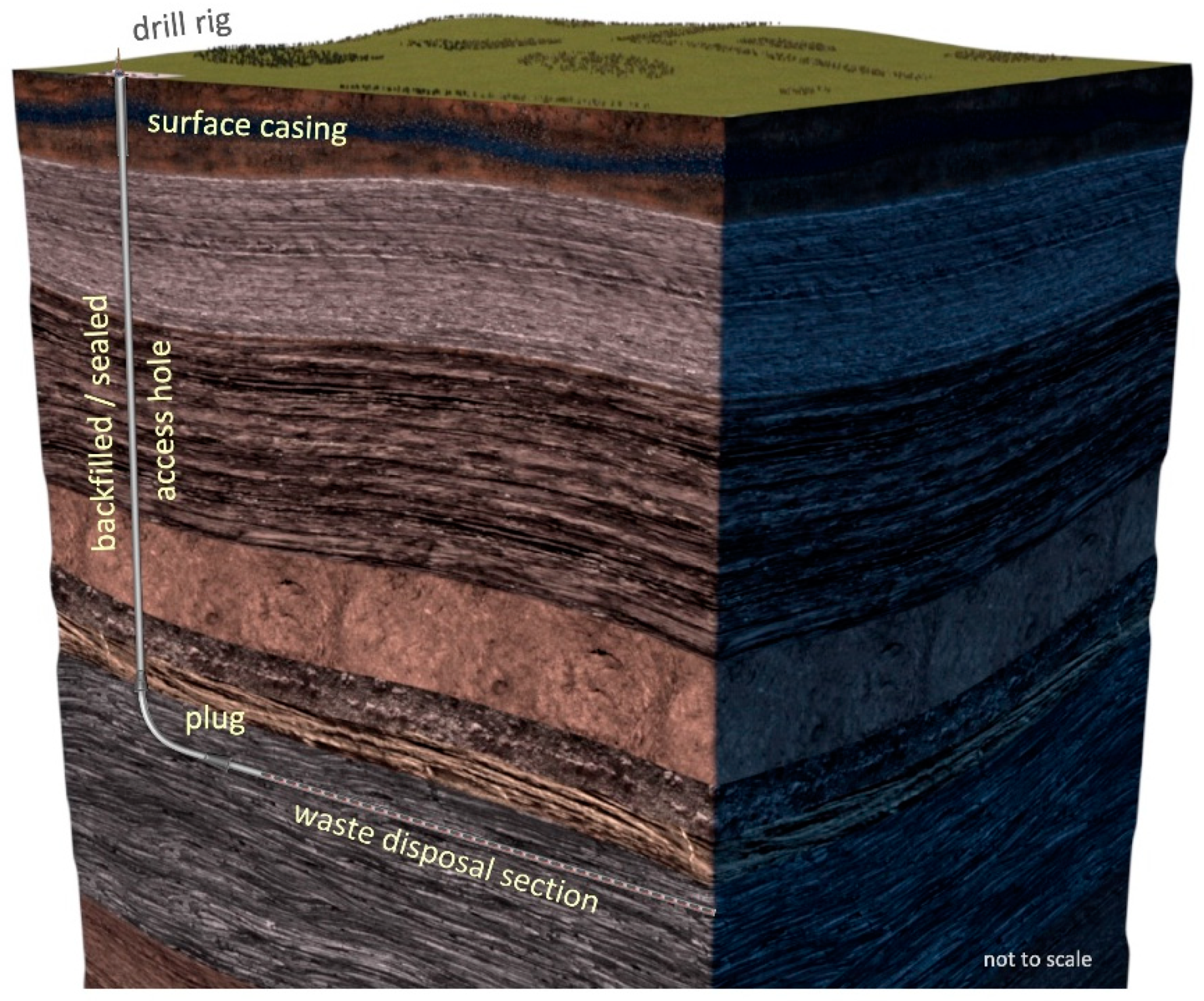
The horizontal drillhole disposal system, and specifically the canister size, is designed for a variety of waste types. For the disposal of Cs/Sr capsules, canisters are on the order of 12 cm in diameter and 60 cm in length. For the disposal of SNF assemblies, the canisters are wider and longer, with each canister holding one fuel assembly. Each assembly is placed in a CRA cylinder with an end plate already attached; the canister filler is added, and the other end plate is positioned and sealed. Figure 1 shows the vertical and horizontal drillhole sections of a representative disposal system. The vertical section goes to the disposal depth, where the drillhole turns to horizontal for the waste disposal section. The EBS comprises the engineered materials placed within a repository, including the waste form, waste canisters, filler materials, backfill and seals. Components of the EBS are to work in combination to prevent the release and transport of radionuclides from the EBS to the host rock for the regulated period and beyond. The canister is a crucial component of the EBS.
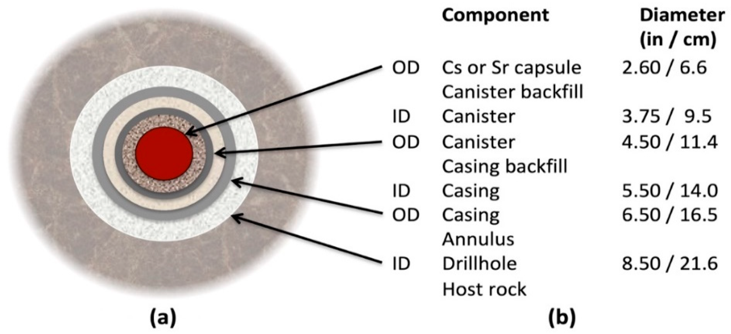
The configuration of the EBS for the disposal of Cs/Sr capsules is representative of the components, drillhole and host rock for an actual disposal project. The representative segment of the horizontal drillhole for this analysis comprises one canister in a steel casing. Each Cs/Sr capsule is inserted in a Ni-Cr-Mo alloy canister and sealed. Figure 2 shows a cross-sectional schematic and dimensions of components in a horizontal drillhole for disposal of cesium or strontium capsules [27]. The canister is 0.6 m long with 11.4 cm outer diameter, with a wall thickness of 9.5 mm. Canisters are emplaced within a steel casing that is 14 cm inner diameter with a wall thickness of 12.5 mm. The outer diameter of the casing is 16.5 cm, and the drillhole diameter is 21.6 cm. For this configuration, the spacing between canisters is 0.6 m, and the depth of the horizontal disposal section is 1 km.
Alloy 625 (UNS N06625) is a representative of corrosion-resistant Ni-Cr-Mo alloys [28]. The chemical composition of Alloy 625 used for calculations in weight percent and atomic percent are presented in Table 1. Other values for Alloy 625 used in the analysis are a molar mass of 60.6 g/mol, a density of 8.44 g/cm3 and a molar volume of 7.18 cm3/mol.
Grade API-5CT L80 steel belongs to a group of corrosion-resistant casing grades and was selected for the casing. For calculations, the steel composition in weight percent is 87 wt% Fe and 13 wt% Cr and the composition in atomic percent is 85 at.% Fe and 15 at.% Cr. Other values for L80 steel used in the analysis are a molar mass of 53.3 g/mol, a density of 7.7 g/cm3 and a molar volume of 7.18 cm3/mol.
3. Methods
The following elements comprise the determination of corrosion performance for the case analyzed here:
- Description of the representative EBS design for disposal of Cs/Sr waste capsules
- Determination of the evolution of the temperature path from thermal simulation and the evolution of the aqueous environment for a deep horizontal drillhole
- Designation of a series of zones relevant to corrosion performance
- Assignment of corrosion rates for Alloy 625 and L80 steel for each zone
- Calculation of EBS corrosion performance.
Metal loss over time and the time of first through-wall perforation were calculated for the CRA canisters and steel casing. In addition, the amounts of hydrogen generated and metal oxides formed were determined for the overall corrosion reaction. To stress the system beyond expected values, the corrosion rates that were assigned are higher than expected for the general corrosion of passive metals. The intent was to gain insight into the EBS performance under accelerated corrosion rates to assess the progression of corrosion damage and the corresponding hydrogen generation and metal oxide formation.
Reported passive corrosion rates for Ni-Cr-Mo alloys in a wide range of environments and the rates for steel in anaerobic environments are on the order of 0.01 µm/year [3,7,11,17,23]. The assigned rates were about a factor of 100 higher than these expected values. Analyses with more realistic rates than those used in this stressed scenario would significantly extend the canister and casing life projections for deep horizontal drillhole disposal.
The time from canister emplacement through 10,000 years was divided into five zones based on the corrosivity of the environment and corrosion resistance of the materials. Duration and environment for each zone were based on an analysis of the evolution of the environment and simulations of the temperature evolution. A single, constant corrosion rate was assigned for each zone. Corrosion penetration was calculated from the corrosion rate and duration of the period. Cumulative metal loss determined the remaining wall thicknesses.
Hydrogen generation and oxide formation were determined from the amount of metal loss for Alloy 625 and L80 steel. Both metals corrode congruently, thus the elemental constituents go into solution at the same atomic concentrations as in the bulk metal. After an early transition period from a moderately oxidizing condition, the horizontal drillhole environment is anaerobic and reducing. The corrosion reactions for the major elemental constituents, Fe, Ni, Cr and Mo, under anaerobic conditions are shown below. All four apply to Alloy 625, and the iron and chromium reactions apply to L80 steel.
3Fe + 4H2O → Fe3O4 + 4H2
Ni + H2O → NiO + H2
2Cr + 3H2O → Cr2O3 + 3H2
Mo + 2H2O → MoO2 + 2H2
An alternative corrosion reaction for iron and water in anaerobic conditions yields the formation of ferrous hydroxide (Fe(OH)2) and hydrogen. The Fe(OH)2 is stable at lower temperatures, but it is predicted to convert to the more thermodynamically stable magnetite (Fe3O4) by the Schikorr reaction at higher temperature [19]. The anaerobic corrosion of carbon steel was studied in artificial ground waters and in alkaline solutions [18,29]. Analysis of long-term corrosion tests under a range of conditions, including cementitious environments, found Fe3O4 to be the predominant corrosion product [18]. Results for the amount of hydrogen generated depend on which iron corrosion product is used. The production of Fe3O4 rather than Fe(OH)2 yields 0.33 moles more hydrogen per mole of iron consumed. Because the ambient temperature at drillhole depth is 60 °C and temperature rises after canisters are emplaced, the production of Fe3O4 is used to determine hydrogen production.
Hydrogen generated per mole of metal corroded is based on the mole fraction of elements in the metal and hydrogen generated per mole of each element. For Alloy 625, the mole fractions of nickel, chromium, molybdenum and iron are 0.60, 0.27, 0.06 and 0.05, respectively. The hydrogen generated for Alloy 625 is 1.19 mole of hydrogen per mole of metal corroded. For L80 steel, the mole fractions of iron and chromium are 0.85 and 0.15, respectively. The hydrogen generated for L80 steel is 1.36 mole of hydrogen per mole of metal corroded. The moles of hydrogen generated was calculated from the moles of metal loss per square meter of the metal surface area. The surface area of the canisters is 0.24 m2. Values are reported per meter of casing where the casing surface areas per meter for the inner surface, outer surface and total surface are 0.44 m2, 0.52 m2, and 0.96 m2, respectively.
A volume expansion of solids accompanies the formation of metal oxides. The oxides formed from Alloy 625 are NiO, Cr2O3, MO2 and Fe3O4, and oxides from L80 steel are Fe3O4 and Cr2O3. Metal oxide formation per mole of alloy corroded is the sum of the mole fraction times oxide formation per mole of each element. For Alloy 625, 2.09 moles of oxide are formed per mole of the alloy, and for L80 steel, 1.78 moles of oxide are formed per mole of the steel. The volume of oxide expansion is the volume of oxides formed minus the volume of metal consumed. Calculations are made for amounts of hydrogen and metal oxides formed per square meter of metal surface, and values are reported per canister and per meter of casing.
4. Evolution of the Environment
4.1. Evolution of Temperature
Determination of the evolution of temperature is essential for assessing the corrosion behavior of canisters for nuclear waste disposal and the overall performance of the EBS, because temperature impacts both corrosion resistance of the metals and corrosivity of the environment. In the passive state, metals are protected by a thin, self-forming film on the surface, and general corrosion rates of passive metals are extremely low, on the order of 0.01 µm/year. Localized corrosion processes, such as pitting and crevice corrosion, are risks to the durability of passive films, and temperature is a critical factor for the onset of localized corrosion. Many passive metals will not pit at a temperature below a certain value, referred to as the critical pitting temperature [30]. Determination of temperature effects on the durability of passive films has been a crucial issue for evaluation of canister materials [3,11,31,32].
For deep horizontal drillholes, the evolution of temperature is determined by thermal simulations [27,33]. The evolution of temperature rise above the ambient temperature of the host rock is determined for a given EBS configuration and the heat output from the nuclear waste. This can then be applied to a specific scenario with a given ambient temperature to determine the temperature evolution of the components of the EBS. There is a common thermal response for all configurations, i.e., a heat-up stage to maximum temperature followed by a long, slow cool-down stage back to ambient rock temperature. The method and form of results are demonstrated in the next two figures.
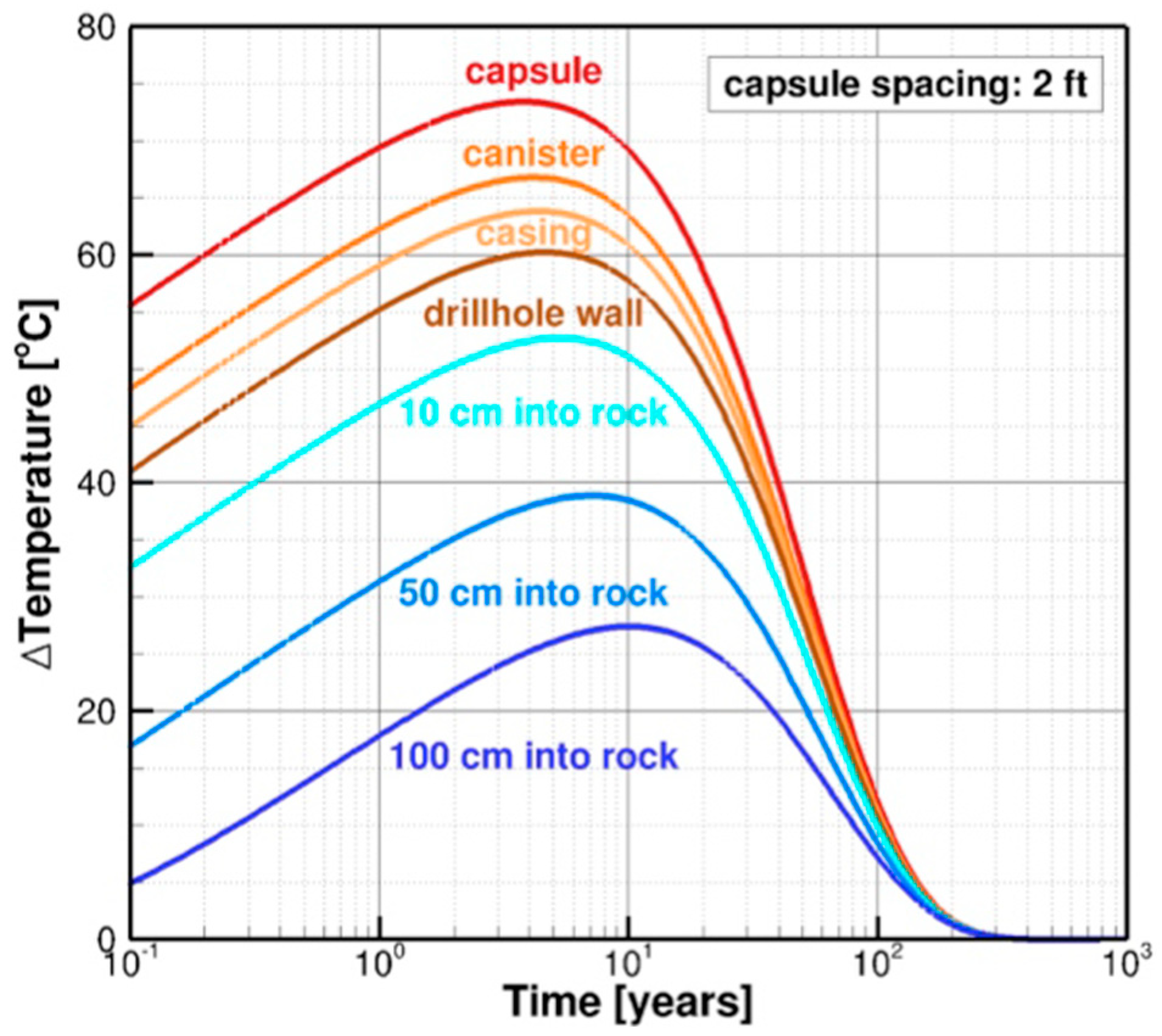
The temperature evolution at various radial distances from the center of a capsule is shown in Figure 3 for an EBS configuration for disposal of Cs/Sr waste [27]. The simulation is for an initial heat output of 100 watts per capsule and a capsule emplacement spacing of 2 ft (0.6096 m). The temperature profiles for EBS components from the capsule out to the host rock are shown. Maximum temperatures are reached after 4–5 years. The maximum temperature increases are about 73 °C for the capsule, 67 °C for the canister, and 63 °C for the casing. The EBS returns to ambient rock temperature after about 300 years.
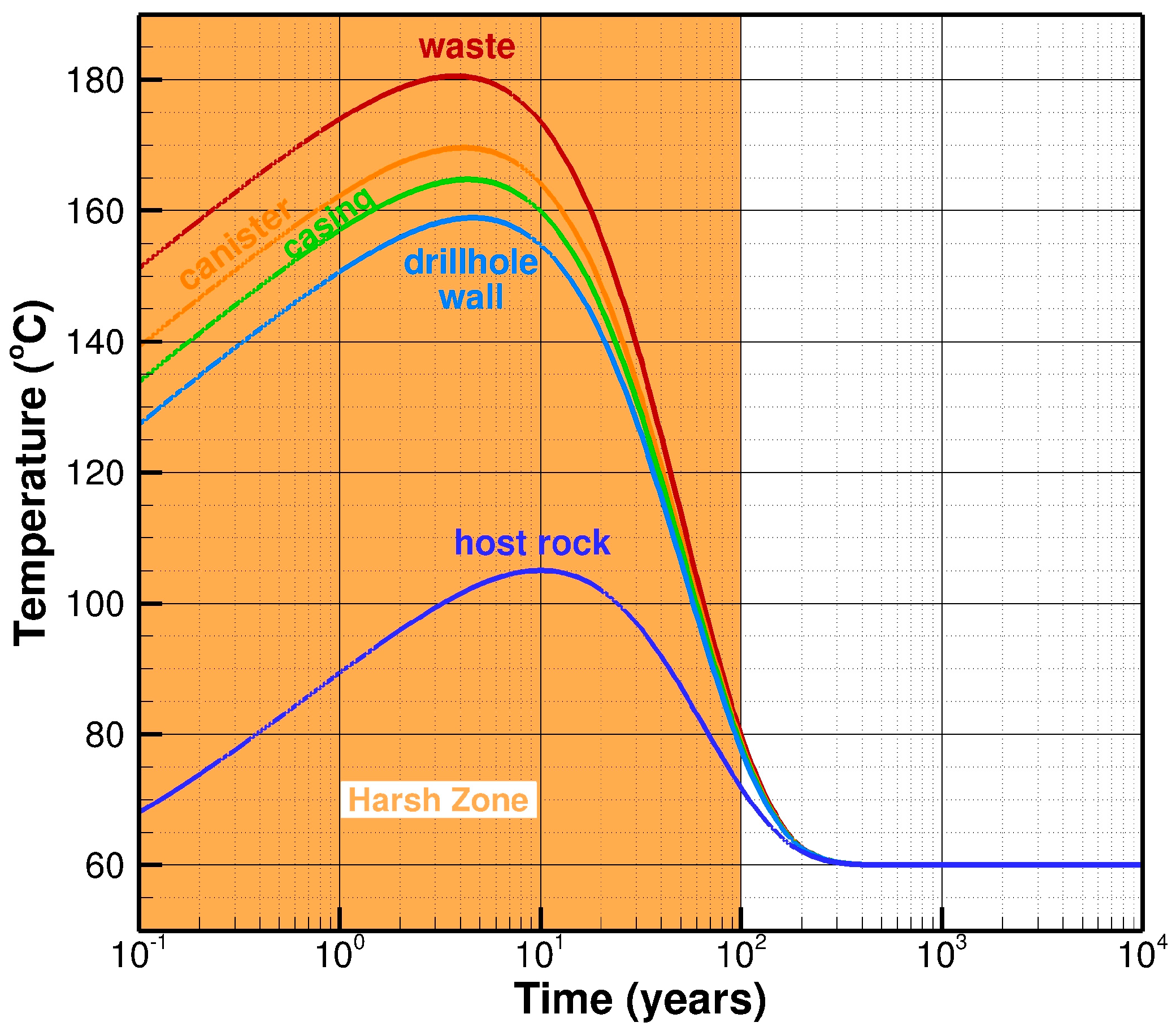
A similar temperature response was applied to a specific scenario, and the evolution of temperature of EBS components is shown in Figure 4. The thermal response is for a strontium capsule with an initial heat output of 164 watts and capsule spacing of 0.6 m. The ambient temperature is 60 °C and heating to maximum temperature and the start of cool down occurs about 4–5 years after canister emplacement. The maximum canister wall temperature is 170 °C after about four years, and the maximum casing temperature is 165 °C after about five years. The canister cools to 120 °C after 40 years and 80 °C after 100 years. The EBS returns to the ambient temperature of 60 °C after about 300 years. The demarcation highlights an early, aggressive stage of about 100 years where temperatures are above 80 °C.
4.2. Evolution of the Aqueous Environment
Important properties of the aqueous environment are chemical composition and concentration, oxidizing power (Eh) and acidity/alkalinity (pH). Information is needed for the evolution of the aqueous environment between the canisters and casing, between the casing and drillhole, and the pore water in the rock. The properties ascribed here are characteristic, and the details of water chemistry evolution are not addressed.
For the representative case analyzed here, the horizontal drillhole is in fully saturated rock and anoxic pore waters. Ambient conditions for the drillhole at 1 km depth are a temperature of 60 °C and a pressure of 10 MPa. Depending on drillhole location, pore waters in the rock can have multiple dissolved species over a wide range of concentrations. Typical pore waters are a chloride brine, and chloride concentration can range from dilute to concentrated levels. Other dissolved anionic species can be present in lesser concentrations. The brines are anoxic, and the environment is reducing. Alkalinity ranges from near neutral to mildly alkaline. Process fluids from drilling, installation of the casing, and emplacement of canisters may contain oxygen, and introduced oxygen creates a moderately oxidizing condition in the early stages of waste disposal. Soluble oxygen within the drillhole is depleted by reaction, sorption and transport. The corrosion process for the steel casing is a primary factor in the consumption of oxygen. Consequently, the environment inside and outside of the steel casing evolves from moderately oxidizing waters to anoxic and reducing waters.
The representative case has the annular space between the casing and rock filled with cement. Pore waters in cement are initially moderately alkaline, but alkalinity declines with time. The annular space between the canister and the casing is filled with bentonite or mineral-based material that is adjusted to moderate alkalinity. Alternate or modified fillings can be used to enhance EBS performance. Until the casing is perforated, it is a barrier between the inner canister/casing environment and the outer casing/drillhole environment.
Corrosion processes in the EBS modify the environment. Corrosion of steel consumes oxygen. Hydrogen generation and metal oxide formation accompany metal loss by corrosion in the anoxic environment. Hydrogen and metal oxides can alter the chemistry of the environment as well as affect the sorption and transport of species. Volume expansion accompanies metal oxide formation and can affect pressure and transport in and from the EBS.
An early, aggressive stage (harsh zone) of about 100 years is highlighted in Figure 4. The aggressive condition is high temperature with multi-ionic, moderately oxidizing waters. Hot, multi-ionic, oxidizing waters can be highly corrosive. After the aggressive stage, the environment is anoxic and reducing. With the exception of the proposed Yucca Mountain repository, all other proposed underground disposal repositories and this horizontal drillhole system are located in the saturated rock. Consequently, the amount of oxygen available for corrosion is limited to that introduced in the repository prior to closure. Horizontal drillholes have less introduced oxygen than mined repositories, in large part due to the mine’s ventilation during operations and the much larger volume of rock removed.
5. Corrosion, Hydrogen Generation and Oxide Formation
5.1. Effect of Corrosion Rate on Metal Loss, Hydrogen Generation and Oxide Formation
The annual amounts of metal loss, hydrogen generation, and metal oxide formation are determined for a range of corrosion rates. The rates span four or five orders of magnitude. The lower rates are at reported values for the general corrosion of passive metals, and the higher rates extend to values for the general corrosion of active metals. For each corrosion rate (µm/year), the annual weight loss (g/m2), moles of hydrogen generated (mol/m2), volume of oxide generated (cm3/m2) and volume expansion from oxide formation (cm3/m2) are presented. The value for volume of metal consumed (cm3/m2-year) is equal to the value for the corrosion penetration rate (µm/year).
Data for the canisters made of Alloy 625 are presented in Table 2 for corrosion rates of 0.01–10 µm/year. Over the range of corrosion rates, the weight loss is from 0.084 to 84 g/m2-year. There are 1.19 moles of hydrogen generated per mole of metal corroded, and hydrogen generation ranges from 0.002 to 1.7 mol/m2-year hydrogen per square meter of canister surface. There are 1.78 moles of metal oxide produced per mole of Alloy 625 that is corroded, and the volume of metal oxide corrosion products ranges from 0.04 to 43 cm3/m2-year of canister metal. Volume expansion from oxide formation is the volume of oxides formed minus the volume of metal loss, and the expansion ranges from 0.03 to 33 cm3/m2-year of canister metal. After 100 years, the solids expansion rates are for corrosion rates of 1 µm/year and 10 µm/year are 0.3 mm and 3.3 mm, respectively.
The last column shows the thickness of the oxide layer after 100 years. Presuming no porosity in the oxide layer, the thicknesses range from less than a micron at the lowest corrosion rate to about 4 mm after 100 years at the highest corrosion rate. For a canister with a 10 mm-wall thickness, at the lowest corrosion rate of 0.01 µm/year, the wall thickness after 10,000 years is 9 mm. At a corrosion rate of 1 µm/year, 200 moles of hydrogen and 4300 cm3 of oxides are formed after 1000 years.
Data for an L80 steel casing are presented in Table 3 for corrosion rates of 0.01–100 µm/year. Over the range of corrosion rates, the weight loss ranges from 0.08 to 770 g/m2-year. For L80 steel, 1.36 moles of hydrogen are generated per mole of metal corroded, and hydrogen generation ranges from 0.002 to 20 mol/m2-year hydrogen per square meter of canister surface. There are 2.09 moles of metal oxide produced per mole of L80 steel corroded. The volume of metal oxide corrosion products ranges from 0.01 to 1200 cm3/m2-year of canister metal. The volume expansion of solids from the formation of these corrosion products ranges from 0.1 to 1100 cm3/m2-year of canister metal.
For an L80 steel casing with a 12.5 mm wall thickness corroding at 1 µm/year on the inner and outer surfaces, the steel is fully consumed after about 6000 years. Hydrogen formed is 1200 mol/m2 of casing surface, and volume of metal oxides formed is 72,000 cm3/m2 of casing surface.
5.2. Metal Loss Over 10,000 Years
The objective of this aspect of the analysis was to determine the progression of corrosion damage for a representative EBS configuration to assess the robustness of the system for containment of radionuclides. The analysis was based on: (a) the determination of the evolutionary path of the environment; and (b) the description of the EBS design and in particular the materials for construction of the canisters and the casing. Along the evolutionary path, the corrosion performance was determined by the corrosivity of the environment and the corrosion resistance of the material. Cumulative damage was the sum of the corrosion damage at each step.
The evolution of temperature for this analysis follows temperature profiles shown in Figure 4. Heating to maximum temperature and start of cool-down occur within 4–5 years after canister emplacement. The maximum temperatures of the EBS components are 182 °C for the capsule, 170 °C for the canister wall, 165 °C for the casing, 160 °C for the drillhole wall, and 105 °C at 1 m into the rock. The heat-up extends a few meters into the host rock. After 20 years, the temperature has cooled to 120 °C and after 100 years to 80 °C. This is followed by a slow cool-down to the ambient temperature of 60 °C after about 300 years.
Five corrosion zones over a 10,000-year period are identified to follow this evolution of temperature and the environment.
- Zone I, Years 0–2: During this early transition period, the corrosion resistance of the metals changes and the environment evolves toward reducing conditions. Exposure conditions are moderately oxidizing from oxygen introduced during the drilling, casing installation, and canister emplacement. Initial heat-up has begun, and there are fresh metal surfaces on the canisters and casing. While oxygen is present, the corrosion reaction produces ferric (Fe3+) containing compounds such as Fe(OH)3, and no hydrogen is produced. As corrosion proceeds, oxygen is consumed, the ferric species are reduced, and hydrogen production commences. On conversion to Fe3O4, more hydrogen is produced.
- Zone II, Years 2–20: During the second period, the highest EBS temperatures are reached, cool-down begins, oxygen has been consumed, and conditions transition to anoxic and reducing.
- Zone III, Years 20–100: For the third period, the temperature has cooled from 120 °C to 80 °C. The environment throughout is anoxic and reducing.
- Zone IV, Years 100–1000: For the fourth period, the temperature has cooled further to 60 °C. The environment throughout is anoxic and reducing.
- Zone V, Years 1000–10,000: The temperature is still 60 °C (the ambient rock temperature) and remains steady for 10,000 years and beyond. The environment is anoxic and reducing.
The characteristic thermal response described for the five corrosion zones above can be compared to the simulation for Sr capsules shown in Figure 4. While the scenarios were nearly identical, a distinction was that the Sr capsules cool to 120 °C at 40 years, while cooling to 120 °C occurs at 20 years in this corrosion zones analysis. This difference affected the duration of the corrosion zones between 2 and 100 years. Slower cooling to 120 °C had the canister at a higher corrosion rate for an additional 20 years, and the period for cooling to 80 °C was shortened by 20 years. The difference had no significant impact on the findings. For the canister analyzed here, the metal penetration calculated at 100 years is 120 µm and it would be 140 µm for the Sr capsule simulation. For the steel casing, the metal penetration calculated here at 100 years is 270 µm, and it would be 310 µm for the Sr capsule simulation.
Assigned corrosion rates were higher for the first three zones, which comprise an initial aggressive stage of 100 years. During the latter two zones, corrosion rates are extremely low for Alloy 625 and steel exposed to anoxic and reducing environments. After the early years, corrosion rates decrease dramatically for three primary reasons: (1) the environment evolves from moderately oxidizing to highly reducing as residual oxygen in the drillhole is consumed and conditions become anoxic; (2) the heat-up and cool-down periods have gone through the maxima, and temperatures have cooled considerably; and (3) the thin, self-forming, protective film on the passive metal provides additional corrosion resistance [8]. The structure and composition of the air-formed film change on exposure to the drillhole environment [3,34,35,36]. The corrosion resistance of the alloy has become even greater as the passive film becomes more protective over the first months and years. With time, the buildup of corrosion products and deposits on the thin passive film also slows corrosion rates.
For Alloy 625, the corrosion rate, metal loss per period, and remaining wall thickness are presented in Table 4. The corrosion rate for the first 20 years (Zone I and II) is set at 2 µm/year for the more aggressive conditions from higher temperatures, initial aerobic conditions, and fresh metal surfaces. During the remainder of the primary heat-up and cool-down cycle, the rate for 20–100 years (Zone III) was set at 1 µm/year. The corrosion rate after 100 years (Zones IV and V) was set at 0.1 µm/year for corrosion of passive metals in the anoxic and reducing environment.
The excellent corrosion resistance of the Ni-Cr-Mo alloy is reflected in the extremely low metal penetration rates. The metal loss is 0.4 mm at 1000 years, and the remaining wall thickness at 10,000 years is 8 mm. While general corrosion is the mode of corrosion, the advancing corroded surface is not perfectly smooth; it has some shallow hills and valleys. In addition, the mechanical strength of the canister decreases as a result of the metal loss. The time to perforation of a canister is set at the time when 50% of the wall thickness has corroded away, and, using this criterion, the first canister perforation is after 40,000 years.
The corrosion behavior of L80 steel casing is presented in Table 5. Corrosion rates are highest during the initial periods while residual oxygen is being consumed and higher temperatures are experienced. The corrosion rate for Years 0–2 (Zone I) is 20 µm/year, and the rate is decreased to 4 µm/year for Years 2–20 (Zone II). For Years 20–100 (Zone III), the rate is 2 µm/year for corrosion in higher temperature, anoxic brines. The corrosion rate for the last two periods (Zone IV and V) is 1 µm/year as temperature decreases further and reaches near-ambient conditions.
The steel metal loss per side of the casing at 100 years is about 0.5 mm and at 1000 years is about 2.5 mm. The remaining casing-wall thickness is 12 mm and 10 mm at 100 years and 1000 years, respectively. All of the steel is consumed after about 6000 years. The corroded surface has shallow hills and valleys, and the mechanical strength of the casing decreases as a result of the metal loss. The time-to-perforate a casing is set at the time that 50% of the wall thickness has corroded away, and, using this criterion, the first casing perforation is at nearly 3000 years. Until the first perforation, the casing is a barrier to contact and transport between the canister-casing and the casing–drillhole–rock environment.
5.3. Hydrogen Generation and Oxide Formation
5.3.1. Canister Corrosion Products
In oxygen-free, reducing waters, hydrogen generation and metal oxide formation are products of the metal corrosion process. During the initial aerobic period, ferric containing iron oxides such as Fe(OH)3 are formed rather than Fe3O4, and no hydrogen is produced. The reported values during the aerobic period overstate the amounts of hydrogen formed. The metal oxides formed from Alloy 625 are NiO, Cr2O3, MO2 and Fe3O4. The chemical reactions for corrosion of nickel, chromium, molybdenum and iron are presented above.
The amounts of hydrogen formed during each corrosion zone per square meter of Alloy 625 and per canister are presented in Table 6. The surface area of each canister is 0.24 m2. The cumulative hydrogen formed on a canister after 100 and 1000 years is about 4.5 and 8.5 moles, respectively.
The rates of hydrogen generated decrease significantly with time. Hydrogen generation rates are highest at about 0.08 cm3/year for the first 20 years (Zones I and II) and drop to about 0.04 cm3/year for Zone III. After 100 years (Zone IV and IV), the rate is lower still and remains at approximately 0.004 cm3/year.
The amounts of metal oxide formed from canister corrosion are presented in Table 7. The moles of oxide formed are 1.78 times the moles of metal consumed. At 100 years, the volume of oxide formed is about 500 cm3/m2, and the resulting expansion from oxide formation is about 400 cm3/m2. The oxide expansion rate decreases over time from about 8.5 cm3/ m2-year during the first 20 years (Zones I and II) years to 4.3 cm3/m2-year during Zone III. After 100 years, the expansion rate decreases further to about 0.4 cm3/m2-year during Zones IV and V.
Metal oxides formed by the corrosion process build up a deposit layer on the metal surface on top of the thin protective film. The thickness of the oxide layer is about 0.5 and 0.9 mm after 100 and 1000 years, respectively.
5.3.2. Casing Corrosion Products
As with the canister corrosion, hydrogen generation and metal oxide formation are products of the metal corrosion process. During the initial aerobic period, ferric containing iron oxides such as Fe(OH)3 are formed rather than Fe3O4, and no hydrogen is produced. The reported values during the aerobic period overstate the amounts of hydrogen formed. The metal oxides formed from L80 steel are Fe3O4 and Cr2O3. The corrosion reactions for iron and chromium reacting with water are presented above. The moles of hydrogen formed during each corrosion zone per square meter of L80 steel and the moles per meter length of casing are presented in Table 8. The inner surface area of the casing is 0.44 m2/m, and the combined inner and outer surface area is 0.96 m2/m. The moles of hydrogen formed during subsequent zone increases, while the rate of generation decreases. For Zone I, the formation rate is 3.8 mols/m2-year, and the rate falls to 0.2 mols/m2-year after the first 100 years. The steel casing is completely consumed after about 6000 years. The cumulative hydrogen formed on a canister after 100 and 1000 years is about 4.5 and 8.5 moles, respectively.
Metal oxide formed and volume expansion from oxide formation per zone are presented in Table 9. Each mole of steel consumed forms 2.09 moles of metal oxides. The values presented are for a meter length of casing, and the inner surface area of the casing is 0.44 m2. The volume of oxide formation is greater for each subsequent zone, while the corresponding rate of oxide generation decreases. For Zone III (20–100 years), 260 mols/m of oxide formed per meter of casing, the volume of oxide formed is 2000 cm3/m, and the corresponding expansion from solids formation is 1800 cm3/m.
The metal loss of the casing is about 0.5 and 2.5 mm after 100 and 1000 years, respectively. The oxide thickness on each side of the casing is about 3 mm after 100 years. The steel casing is completely consumed after about 6000 years.
6. Discussion
6.1. Evolution of the Environment and the Corrosion Evolutionary Path
To summarize, the evolution of the environment and analysis of the corrosion evolutionary path are keys to the analysis of corrosion performance of the EBS for deep horizontal disposal systems. This evolution is described for five corrosion zones over a period of 10,000 years. After canister emplacement, temperatures rise from the residual decay heat emanating from the waste forms and then decrease as the radioactivity subsides. An initial harsh, aggressive stage was identified. During this stage, the environment is hot at 120–170 °C and is initially moderately oxidizing. After about 20 years, any oxygen in the waters has been consumed, and the environment becomes both anoxic and reducing. After about 300 years, the EBS has returned to 60 °C, the ambient rock temperature at the horizontal drillhole depth. The host rock at horizontal drillhole depth is fully saturated and the anoxic and reducing conditions are constant throughout the remainder of the 10,000-year period. After the initial aggressive stage, the anaerobic environment in the EBS is benign and has low potential to induce corrosion.
The pore waters in the fully saturated rock contain multiple anionic species, but chloride-based brines are typical. The brines are anoxic and reducing and alkalinity ranges from near neutral to mildly alkaline. The EBS is suitable for the use of “engineered fluids” within the casing and between casing and drillhole to enhance performance. For the configuration analyzed here, the annular space between the casing and rock formation is filled with cement. The canister/casing annular space is filled with bentonite or mineral-based material that is adjusted to moderate alkalinity. Until the casing is perforated, it is a barrier between the inner canister/casing environment and the outer casing–drillhole environment.
Strong corrosion performance in the evolving EBS environment and high structural strength are the principal criteria for materials selection. Alloy 625, a Ni-Cr-Mo alloy, was selected for canisters for its excellent corrosion resistance in high-temperature, hostile environments. Corrosion rates are on the order of 0.01 µm/year in a wide range of environments [3,7,11,23]. This CRA alloy is protected by a thin, self-forming layer (passive film) on its surface. After 1000 years, canister metal loss is calculated to be about 0.4 mm, and after 10,000 years a 9.5 mm-thick canister wall remains over 8 mm thick. The canister remains perforation free for over 40,000 years, and that provides a non-permeable barrier for containment of radionuclides and prevention of water entry.
Less corrosion-resistant materials than Ni-Cr-Mo alloys and with lower costs are suitable for anaerobic, reducing environment, but for disposal of nuclear waste, there are several special overriding needs. These include a crucial need for safe and reliable containment, and a need for containment over an unprecedented length of time. Several metals are passive in the benign, anaerobic environment; however, the canisters must survive the initial aggressive stage and maintain their passivity thereafter. In high-temperature brines, Alloy 22 repassivates readily while two less corrosion resistant alloys, AL6XN and 316L stainless steel, do not [37]. The difference in corrosion resistance is related to the amount of Mo in the alloys.
The key issues are the following: Will the metal remain passive, and—if the passive film is damaged—will it reform spontaneously? If the passive film does not reform, then the metal is severely damaged and penetration rates are rapid. The Ni-Cr-Mo alloys have a durable protective (passive) film that is self-forming even in harsh environments, and they have robust resistance to the localized corrosion processes of pitting, crevice corrosion, and stress corrosion cracking [3,8,23,24]. High durability of the passive film on Ni-Cr-Mo alloys results from a combination of resistance to film breakdown even in highly aggressive environments and the ability to reform (repassivate) after it has been damaged. The alloy composition is a key factor for corrosion resistance. Crevice corrosion resistance was measured as function of chloride concentration and increased chromium, molybdenum and tungsten increased the crevice corrosion resistance of the alloys. Most resistant were Alloy 625 with 22 wt% Cr and 9 wt% Mo; and Alloy 22 with 21 wt% Cr, 13.5 wt% Mo, and 3 wt% W [38].
The durability of the passive film in high temperature brines was compared for Alloy 22 and Alloy Al6XN with Cr 20 wt% and Mo 6 wt% [37,39]. The passive films were mechanically damaged by a diamond scribe and then the repassivation behavior was determined. The passive corrosion rates of the alloys were essentially equal, but the repassivation behavior was quite different. After mechanical damage, the film did reform rapidly on Alloy 22, but on AL6XN the film did not reform and localized corrosion proceeded. In a number of harsh environments, the Ni-Cr-Mo alloys have exhibited stifling and arrest after the initiation of localized corrosion [14,40]. Stifling means that the crevice corrosion rate slowed, and arrest means the crevice corrosion stopped. The durability of a self-forming film, the rapid reformation of the protective film if damaged mechanically or chemically, and the potential for stifling and arrest if localized corrosion initiates are the admirable distinguishing features of Ni-Cr-Mo alloys over alloys with lesser corrosion resistance.
Grade API-5CT L80 is selected from the family of steel casing materials for its structural strength and greater corrosion resistance. After the initial aggressive stage, L80 steel has extremely low corrosion rates. Corrosion rates of passive metals in anaerobic environments are on the order of 0.01 µm/year. The first casing perforation is at nearly 3000 years, and until then it isolates the internal casing environment from external environments.
In addition to corrosion metal loss and its effect on performance of canisters and casings, reactants and by-products of the corrosion reactions impact EBS performance. During the anaerobic stage, oxygen is consumed, and hydrogen and metal oxides are formed from the metal corrosion. Production of hydrogen and formation of oxides tracks the corrosion behavior; rates are higher during the initial aggressive stage and decrease markedly thereafter. More of each corrosion by-product results from corrosion of the steel casing than from corrosion of the Ni-Cr-Mo alloy canisters.
Both hydrogen and metal oxides can affect the environment, transport, sorption and other processes. Some effects are identified here, but the analysis of their impact on EBS performance was not addressed in this study. Hydrogen can be a nutrient for microbiologically activity. In a space with fixed volume, generation of gas and expansion from oxide formation can increase pressure or promote transport from the space. Hydrogen gas formation is minimized by the hydrostatic pressure at horizontal drillhole depth. A volume increase accompanies the metal-to-metal oxide reactions, and the expansion increases pressure in the EBS.
During general corrosion of a passive alloy, a layer of corrosion products forms on the metal surface. After 1000 years, the canister metal loss is about 0.4 mm, and the outer layer of metal oxides is less than 1 mm thick. The time to first perforation of the canister is about 40,000 years. After 100 years, the steel casing metal loss is about 0.25 mm on each side, and the oxide corrosion product thickness is about 3 mm. The steel casing is completely consumed after 6000 years.
6.2. Design and Strategies of EBS for Deep Horizontal Drillholes
Several attributes contribute to the safe and reliable disposal of nuclear waste in deep horizontal drillholes. Categories of these attributes include location of disposal systems and conditions at drillhole depth, EBS design, and the technical basis and safety case.
6.2.1. Location and Conditions at Drillhole Depth
Deep horizontal drillhole sites will be in or below stable geologic formations that have low permeability. The disposal system can be built using conventional materials and construction practices. The oil and gas industry has drilled thousands of horizontal wells in the U.S. There is a small Excavation Disturbed Zone (EDZ) around the drillhole from drilling. The environment along the horizontal disposal section is uniform with respect to being in fully saturated rock with anoxic and reducing pore waters. The hydrostatic pressure at drillhole depth prevents the water from boiling.
6.2.2. EBS Design
The analysis of the evolutionary path of the environment for the selected waste form demonstrates an initial, aggressive corrosion stage that lasts about 100 years. After this stage, the environment becomes benign for the next 10,000 years and beyond. The EBS components are initially heated by decaying radioactive waste, but as the decay rate diminishes cooling occurs and heat is dissipated by the host rock. The linear configuration of disposal canisters and flexible canister spacing allow control of maximum temperature and duration of the thermal pulse.
Oxygen introduced in the drilling fluids, and during casing installation and canister emplacement, coupled with the highest temperatures within the EBS, result in aggressive corrosion conditions. The introduced oxygen is consumed primarily by steel corrosion; however, the transition time to reach anoxic and reducing conditions could be shortened by the reduction of introduced oxygen and by the use of oxygen scavengers or other species to consume oxygen. The fillers in the EBS system are amenable to the addition of constituents that would enhance performance.
Material selection is a crucial determinant of performance. The major challenge is to design a system that makes it through the aggressive, initial period and enters the anaerobic period in a condition to survive for tens of thousands of years. Canisters of Ni-Cr-Mo alloys meet this challenge with extremely low corrosion rates and robust resistance to localized corrosion in high temperature, moderately oxidizing environments. Both Ni-Cr-Mo alloys and steel have strong mechanical properties to temperatures well above those experienced in the EBS, and they can be fabricated and sealed by conventional processes.
Volume expansion from formation of iron corrosion products increases pressure inside and outside of the casing. The pressure could be moderated in the EBS by expansion absorbers, such as empty thin-walled components and expansion zones included along the drillhole. Increasing the drillhole diameter increases volume for expansion and reduction of the amount of steel decreases the volume of metal oxide formed.
6.2.3. Technical Basis and Safety Case
Because the aggressive stage occurs early and is over after about 100 years, the design and analysis of the system are more tenable and within the realm of conventional engineering practices. There is a rich data and knowledge base for Ni-Cr-Mo alloys from the proposed Yucca Mountain repository. For steel, there is substantial data and knowledge from other nuclear waste repository programs. In addition, there is a large experience base from industrial applications in relevant service for both N-Cr-Mo alloys and steel.
The deep horizontal drillhole waste disposal system has favorable attributes that contribute to a strong technical basis for long-term control of radionuclide transport and the reduction of uncertainty in the supporting safety case. In part, this is because the horizontal drillhole disposal system avoids several phenomena and processes that affect other repository systems, complicate their analysis and increase uncertainty. Major contributing factors avoided by deep horizontal drillholes include: two-phase vapor/liquid processes, the effects of boiling on metal surfaces and in surrounding rock, and a large thermal pulse from decay heat that results in a wet-dry-wet cycle over time.
7. Concluding Remarks
An innovative system for disposal of spent nuclear fuel and other high-level radioactive waste in deep horizontal drillholes was analyzed. Key components of the EBS design are canisters made of a highly corrosion-resistant Ni-Cr-Mo alloy and a casing of carbon steel for structural strength. The metal loss from corrosion was analyzed, and the amounts of hydrogen and metal oxides that are formed as by-products of the metal corrosion process were determined. Canisters remained perforation-free for tens of thousands of years. While Ni-Cr-Mo alloys have outstanding resistance to localized corrosion processes (pitting, crevice corrosion and stress corrosion cracking), these processes and galvanic corrosion were not included in the analysis. Beneficial attributes that contribute to the extraordinarily long life of canisters were identified. Several features of the system contributed to a strong technical basis for the analysis and reduced the complexities and uncertainties.
Author Contributions
Conceptualization, J.H.P., S.F., J.A.A. and R.A.M.; Formal analysis, J.H.P.; Funding acquisition, R.A.M.; Investigation, S.F., J.A.A. and R.A.M.; Methodology, J.H.P., S.F. and J.A.A.; Validation, J.H.P., S.F., J.A.A. and R.A.M.; Writing—original draft, J.H.P.; and Writing—review and editing, J.H.P., S.F., J.A.A. and R.A.M.
Funding
This research received no external funding.
Acknowledgments
We acknowledge and appreciate the benefit of the extensive analysis and data from the proposed Yucca Mountain repository and other nuclear waste programs around the world. The authors thank their colleagues for helpful discussions and the staff of Deep Isolation Inc. for their support.
Conflicts of Interest
Joe Payer, Stefan Finsterle and John Apps are paid consultants for Deep Isolation, Inc.
References
- Muller, R.A.; Finsterle, S.; Grimsich, J.; Baltzer, R.; Muller, E.A.; Rector, J.W.; Payer, J.; Apps, J. Disposal of High-Level Nuclear Waste in Deep Horizontal Drillholes. Preprints 2019, 2019040153. [Google Scholar] [CrossRef]
- Deep Isolation Technology. Available online: https://www.deepisolation.com/technology/ (accessed on 13 February 2019).
- King, F. Container materials for the storage and disposal of nuclear waste. Corrosion 2013, 69, 986–1011. [Google Scholar] [CrossRef]
- Payer, J.H.; Carroll, S.A.; Gdowski, G.E.; Rebak, R.B. A Framework for the Analysis of Localized Corrosion at the Proposed Yucca Mountain Repository. In Proceedings of the International High-Level Radioactive Waste Management Conference Proceedings, Las Vegas, NV, USA, 30 April–4 May 2006. [Google Scholar]
- Payer, J.H. Corrosion Resistance of Alloy 22. In Proceedings of the USA Nuclear Waste Technical Review Board Mtg, Washington, DC, USA, 18 May 2004; Available online: www.nwtrb.gov/meetings (accessed on 24 May 2004).
- Steefel, C. The In-Drift Chemical Environment During the Above Boiling Period. In Proceedings of the USA Nuclear Waste Technical Review Board Meeting, Washington, DC, USA, 18 May 2004; Available online: www.nwtrb.gov/meetings (accessed on 19 May 2004).
- Johnson, L.; King, F. The effect of the evolution of environmental conditions on the corrosion evolutionary path in a repository for spent fuel and high-level waste in Opalinus Clay. J. Nucl. Mater. 2008, 379, 9–15. [Google Scholar] [CrossRef]
- Payer, J.H.; Finsterle, S.; Apps, J.A.; Muller, R.A. Corrosion Resistant Alloy Canisters for Nuclear Waste Disposal in Horizontal Drillholes. In Proceedings of the International High-Level Radioactive Waste Management Conference, Knoxville, TN, USA, 14–18 April 2019. [Google Scholar]
- Department of Energy. Yucca Mountain Repository License Application; DOE/RW-0573, Rev. 0; US Department of Energy: Washington, DC, USA, 2008.
- Rebak, R.B.; Mccright, R.D. Corrosion of Containment Materials for Radioactive-Waste Isolation. In ASM Handbook; ASM International: Materials Park, OH, USA, 2006. [Google Scholar] [CrossRef]
- Rebak, R.B.; Payer, J.H. Passive corrosion behavior of alloy 22. In Proceedings of the 11th International High-Level Radioactive Waste Management Conference, Las Vegas, NV, USA, 30 April–4May 2006. [Google Scholar]
- Rebak, R.B. Corrosion testing of nickel and titanium alloys for nuclear waste disposition. Corrosion 2009, 65, 252–271. [Google Scholar] [CrossRef]
- Enos, D.G.; Bryan, C.R. The long-term corrosion performance of Alloy 22 in heated brine solutions. Corrosion 2015, 71, 758–770. [Google Scholar] [CrossRef]
- Dunn, D.S.; Brossia, C.S. Assessment of Passive and Localized Corrosion Processes for Alloy 22 High Level Nuclear Waste Container Materials. In CORROSION 2002; NACE International: Houston, TX, USA, 2002. [Google Scholar]
- Lloyd, A.C.; Shoesmith, D.W.; McIntyre, N.S.; Noel, J.J. Effects of temperature and potential on the passive corrosion properties of alloys C22 and C276. J. Electrochem. Soc. 2003, 150, B120–B130. [Google Scholar] [CrossRef]
- Rebak, R.B.; Crook, P. Influence of the environment on the general corrosion rate of alloy 22 (N06022). In Proceedings of the ASME/JSME 2004 Pressure Vessels and Piping Conference, San Diego, CA, USA, 25–29 July 2004; pp. 131–136. [Google Scholar]
- Smart, N.R. Corrosion behavior of carbon steel radioactive waste packages: A summary review of Swedish and U.K. Research. Corrosion 2009, 65, 195–212. [Google Scholar] [CrossRef]
- Smart, N.R.; Rance, A.P.; Nixon, D.J.; Fennell, P.A.H.; Reddy, B.; Kursten, B. Summary of studies on the anaerobic corrosion of carbon steel in alkaline media in support of the Belgian supercontainer concept. Corros. Eng. Sci. Technol. 2017. [Google Scholar] [CrossRef]
- Reardon, E.J. Anaerobic Corrosion of Granular Iron: Measurement and Interpretation of Hydrogen Evolution Rates. Environ. Sci. Technol. 1995. [Google Scholar] [CrossRef]
- Dinh, H.T.; Kuever, J.; Mußmann, M.; Hassel, A.W.; Stratmann, M.; Widdel, F. Iron corrosion under the enrichment culture of anaerobic microorganisms utilizing metallic iron as an electron donor. Corros. Eng. 2010. [Google Scholar] [CrossRef]
- Martin, F.A.; Bataillon, C.; Schlegel, M.L. Corrosion of iron and low alloyed steel within a water saturated brick of clay under anaerobic deep geological disposal conditions: An integrated experiment. J. Nucl. Mater. 2008. [Google Scholar] [CrossRef]
- Carlson, L.; Karnland, O.; Oversby, V.M.; Rance, A.P.; Smart, N.R.; Snellman, M.; Vähänen, M.; Werme, L.O. Experimental studies of the interactions between anaerobically corroding iron and bentonite. Phys. Chem. Earth 2007. [Google Scholar] [CrossRef]
- Rebak, R.B. Selection of corrosion resistant materials for nuclear waste repositories. Mater. Sci. Technol. 2006, 6, 639. [Google Scholar]
- Shoesmith, D.W. Assessing the corrosion performance of high-level nuclear waste containers. Corrosion 2006, 62, 703–722. [Google Scholar] [CrossRef]
- King, F.; Padovani, C. Review of the corrosion performance of selected canister materials for disposal of UK HLW and/or spent fuel. Corros. Eng. Sci. Technol. 2011, 46, 82–90. [Google Scholar] [CrossRef]
- King, F.; Kolar, M. Lifetime Predictions for Nuclear Waste Disposal Containers. Corrosion 2018, 75, 309–323. [Google Scholar] [CrossRef]
- Finsterle, S.; Muller, R.A.; Baltzer, R.; Payer, J.; Rector, J.W. Thermal Evolution near Heat-Generating Nuclear Waste Canisters Disposed in Horizontal Drillholes. Energies 2019, 12, 596. [Google Scholar] [CrossRef]
- Inconel Alloy 625. Available online: www.specialmetals.com (accessed on 10 December 2018).
- Smart, N.R.; Blackwood, D.J.; Werme, L. Anaerobic corrosion of carbon steel and cast iron in artificial groundwaters: Part 2-Gas generation. Corrosion 2002. [Google Scholar] [CrossRef]
- Frankel, G.S. Pitting Corrosion of Metals A Review of critical Factors. J. Electrochem. Soc. 1998. [Google Scholar] [CrossRef]
- Hornus, E.C.; Giordano, C.M.; Rodŕiguez, M.A.; Carranza, R.M. Effect of temperature on the crevice corrosion resistance of Ni-Cr-Mo alloys as engineered barriers in nuclear waste repositories. In Materials Research Society Symposium Proceedings; Materials Research Society: Cambridge, UK, 2012. [Google Scholar] [CrossRef]
- Carranza, R.M.; Rodríguez, M.A. Crevice corrosion of nickel-based alloys considered as engineering barriers of geological repositories. NPJ Mater. Degrad. 2017. [Google Scholar] [CrossRef]
- Finsterle, S.; Muller, R.A.; Baltzer, R.; Payer, J.; Rector, J.W. Numerical Evaluation of Thermal Effects From Nuclear Waste Disposed in Horizontal Drillholes. In Proceedings of the International High-Level Radioactive Waste Management, Knoxville, TN, USA, 14–18 April 2019. [Google Scholar]
- Orme, C.A. The Passive Film on Alloy 22. In Technical Report UCRL-TR-215277; Lawrence Livermore National Laboratory: Livermore, CA, USA, 2005. [Google Scholar] [Green Version]
- Priyantha, N.; Jayaweera, P.; Macdonald, D.D.; Sun, A. An electrochemical impedance study of Alloy 22 in NaCl brine at elevated temperature. I. Corrosion behavior. J. Electroanal. Chem. 2004, 572, 409–419. [Google Scholar] [CrossRef]
- Macdonald, D.D.; Sun, A.; Priyantha, N.; Jayaweera, P. An electrochemical impedance study of Alloy-22 in NaCl brine at elevated temperature: II. Reaction mechanism analysis. J. Electroanal. Chem. 2004, 572, 421–431. [Google Scholar] [CrossRef]
- Payer, J.; Pharkya, P. Robustness of Passive Films in High Temperature Brines. In Proceedings of the 2008 MRS Fall Meetin, Boston, MA, USA, 1–5 December 2008. [Google Scholar] [CrossRef]
- Ebrahimi, N.; Jakupi, P.; Noel, J.J.; Shoesmith, D.W.; Noël, J.J.; Shoesmith, D.W. The Role of Alloying Elements on the Crevice Corrosion Behavior of Ni-Cr-Mo Alloys. Corrosion 2015, 71, 1441–1451. [Google Scholar] [CrossRef]
- Pharkya, P.; Shan, X.; Payer, J.H. Durability Of Passive Films In High Temperature Brines. In CORROSION 2008; NACE International: Houston, TX, USA, 2008. [Google Scholar]
- Rebak, R.B. Stifling of crevice corrosion in alloy 22 during constant potential tests. J. Press. Vessel Technol. 2009, 131, 14501. [Google Scholar] [CrossRef]
Figure 1.
Depiction of the deep horizontal drillhole system with a vertical access hole and a horizontal waste disposal section.
Figure 1.
Depiction of the deep horizontal drillhole system with a vertical access hole and a horizontal waste disposal section.

Figure 2.
(a) Cross-sectional schematic of components in a horizontal drillhole used for the disposal of heat-generating cesium or strontium capsules; and (b) list of inner diameters (ID) and outer diameters (OD) of the components [27].
Figure 2.
(a) Cross-sectional schematic of components in a horizontal drillhole used for the disposal of heat-generating cesium or strontium capsules; and (b) list of inner diameters (ID) and outer diameters (OD) of the components [27].

Figure 3.
Evolution of temperature change for an initial heat release of 100 W per waste capsule with capsule spacings of 2 ft (0.6096 m) [27].
Figure 3.
Evolution of temperature change for an initial heat release of 100 W per waste capsule with capsule spacings of 2 ft (0.6096 m) [27].

Figure 4.
Thermal simulation of an EBS design for disposal of strontium capsules. The 100-year demarcation highlights an early aggressive stage (Harsh Zone).
Figure 4.
Thermal simulation of an EBS design for disposal of strontium capsules. The 100-year demarcation highlights an early aggressive stage (Harsh Zone).


Table 1.
Chemical composition of Alloy 625 for calculations in weight percent and atomic percent.
| Ni | Cr | Mo | Nb + Ta | Nb | Ta | Fe | |
|---|---|---|---|---|---|---|---|
| wt% | 58 | 23 | 10 | 0 | 2 | 2 | 5 |
| at.% | 59 | 27 | 6 | 0 | 1.3 | 0.7 | 5.4 |
Table 2.
Effect of corrosion rate of Alloy 625 on metal loss, hydrogen generation, oxide formation, and solids expansion.
Table 2.
Effect of corrosion rate of Alloy 625 on metal loss, hydrogen generation, oxide formation, and solids expansion.
| Corrosion Rate Alloy 625 µm/y | Weight Loss g/m2-Year | Moles Loss mol/m2-Year | Hydrogen Formed mol/m2-Year | Oxides Formed mol/m2-Year | Volume Oxides Formed cm3/m2-Year | Solids Expansion cm3/m2-Year | Thickness of Oxide After 100 Years mm |
|---|---|---|---|---|---|---|---|
| 0.01 | 0.084 | 0.001 | 0 | 0 | 0.04 | 0.03 | 0 |
| 0.1 | 0.84 | 0.01 | 0.02 | 0.03 | 0.4 | 0.3 | 0 |
| 1 | 8.4 | 0.1 | 0.2 | 0.25 | 4.3 | 3.3 | 0.4 |
| 10 | 84 | 1.4 | 1.7 | 2.5 | 43 | 33 | 4.3 |
Table 3.
Effect of corrosion rate of L80 steel on metal loss, hydrogen generation, oxide formation, and solids expansion.
Table 3.
Effect of corrosion rate of L80 steel on metal loss, hydrogen generation, oxide formation, and solids expansion.
| Corrosion Rate L80 Steel µm/y | Weight Loss g/m2-Year | Moles Loss mol/m2-Year | Hydrogen Formed mol/m2-Year | Oxides Formed mol/m2-Year | Volume Oxides Formed cm3/m2-Year | Solids Expansion cm3/m2-Year | 100 Years Expansion mm |
|---|---|---|---|---|---|---|---|
| 0.01 | 0.08 | 0.001 | 0 | 0 | 0.01 | 0.1 | 0 |
| 0.1 | 0.8 | 0.01 | 0.02 | 0.03 | 1.2 | 1.1 | 0.1 |
| 1 | 7.7 | 0.14 | 0.2 | 0.29 | 12 | 11 | 1.1 |
| 10 | 77 | 1.4 | 2 | 3 | 120 | 110 | 11 |
| 100 | 770 | 14 | 20 | 30 | 1200 | 1100 | 110 |
Table 4.
Corrosion of Alloy 625 canisters: metal penetration per zone and remaining wall thickness.
| Years After Emplacement | Environment | Corrosion Rate µm/Year | Metal Loss per Zone µm | Wall Thickness mm |
|---|---|---|---|---|
| 2 | Early transition | 2 | 4 | 9.5 |
| 20 | T > 120 °C | 2 | 36 | 9.5 |
| 100 | 80 < T < 120 °C | 1 | 80 | 9.3 |
| 1000 | T < 80 °C | 0.1 | 90 | 9.1 |
| 10,000 | T = 60 °C | 0.1 | 900 | 8 |
Table 5.
Corrosion of L80 steel casing: penetration per zone per side and remaining wall thickness.
| Years After Emplacement | Environment | Corrosion Rate µm/y | Metal Loss per Side per Zone µm | Wall Thickness mm |
|---|---|---|---|---|
| 2 | Early transition | 20 | 40 | 12.4 |
| 20 | T > 120 °C | 4 | 72 | 12.3 |
| 100 | 80 < T < 120 °C | 2 | 160 | 12 |
| 1000 | T < 80 °C | 1 | 900 | 10 |
| 6000 | T = 60 °C | 1 | 5000 | 0.00 |
Table 6.
Hydrogen gas generation per zone per canister of Alloy 625.
| Years After Emplacement | Environment | Hydrogen Formed per m2 mols/m2 | Hydrogen Formed per Canister mols | Hydrogen Formed per Year per Canister mols/year |
|---|---|---|---|---|
| 2 | Early transition | 0.7 | 0.16 | 0.08 |
| 20 | T > 120 °C | 6 | 1.4 | 0.08 |
| 100 | 80 < T < 120 °C | 13 | 3 | 0.04 |
| 1000 | T < 80 °C | 15 | 4 | 0.004 |
| 10,000 | T = 60 °C | 150 | 35 | 0.004 |
1 Volume at temperature and pressure of deep horizontal drillhole.
Table 7.
Oxide formation per zone from Alloy 625 corrosion.
| Years After Emplacement | Environment | Moles Oxide Formed mols/m2 | Volume Oxide Formed cm3/m2 | Volume Oxide Expansion cm3/m2 | Volume Oxide Formed per Year cm3//m2-year |
|---|---|---|---|---|---|
| 2 | Early transition | 1 | 17 | 13 | 8.5 |
| 20 | T > 120 °C | 9 | 150 | 120 | 8.5 |
| 100 | 80 < T < 120 °C | 20 | 340 | 260 | 4.3 |
| 1000 | T < 80 °C | 22 | 385 | 300 | 0.4 |
| 10,000 | T = 60 °C | 220 | 3850 | 3000 | 0.4 |
Table 8.
Hydrogen formed from corrosion of L80 steel casing per meter per zone.
| Years After Emplacement | Environment | Hydrogen Formed mols/m2 | Hydrogen Formed on Casing ID mols/m | Total Hydrogen Formed on Casing mols/m |
|---|---|---|---|---|
| 2 | Early Transition | 8 | 3 | 7 |
| 20 | T > 120 °C | 14 | 6 | 13 |
| 100 | 80 < T < 120 °C | 30 | 13 | 30 |
| 1000 | T < 80 °C | 170 | 75 | 165 |
| 6000 | T = 60 °C | 950 | 420 | 900 |
Table 9.
Oxide formation from corrosion per meter of L80 Steel per side per meter of casing.
| Years After Emplacement | Environment | Moles of Oxide Formed mols/m | Volume of Oxide Formed cm3/m | Oxide Formed per Year cm3/m-year | Solids Expansion cm3/m |
|---|---|---|---|---|---|
| 2 | Early transition | 5 | 220 | 110 | 200 |
| 20 | T > 120 °C | 20 | 900 | 50 | 820 |
| 100 | 80 < T < 120 °C | 50 | 2000 | 25 | 1800 |
| 1000 | T < 80 °C | 260 | 11,000 | 12 | 10,000 |
| 6000 | T = 60 °C | 1500 | 62,000 | 12 | 56,000 |
© 2019 by the authors. Licensee MDPI, Basel, Switzerland. This article is an open access article distributed under the terms and conditions of the Creative Commons Attribution (CC BY) license (http://creativecommons.org/licenses/by/4.0/).
Share and Cite
MDPI and ACS Style
Payer, J.H.; Finsterle, S.; Apps, J.A.; Muller, R.A. Corrosion Performance of Engineered Barrier System in Deep Horizontal Drillholes. Energies 2019, 12, 1491. https://doi.org/10.3390/en12081491
AMA Style
Payer JH, Finsterle S, Apps JA, Muller RA. Corrosion Performance of Engineered Barrier System in Deep Horizontal Drillholes. Energies. 2019; 12(8):1491. https://doi.org/10.3390/en12081491
Chicago/Turabian StylePayer, Joe H., Stefan Finsterle, John A. Apps, and Richard A. Muller. 2019. "Corrosion Performance of Engineered Barrier System in Deep Horizontal Drillholes" Energies 12, no. 8: 1491. https://doi.org/10.3390/en12081491
Note that from the first issue of 2016, this journal uses article numbers instead of page numbers. See further details here.