1. Introduction
In recent decades, energy has become one of the key factors to be a powerful country for both developing and developed countries [
1]. Some countries have their own natural energy sources, fossil fuels, which will be depleted in the near future. However, many countries have no fossil fuel sources or they have only a limited amount. Therefore, all countries, whether they have fossil fuel sources or not, strive to produce their energy from alternative energy sources [
2,
3,
4]. Consequently, nuclear energy and renewable energy sources such as solar [
5], wind [
6,
7], geothermal [
8] and biomass [
9], which are sustainable and environmentally friendly, draw the attention of most governments, technology companies and scientists. Biogas, one of the anaerobic digestion products, is also among the most attractive alternative energy sources [
10,
11,
12,
13]. There are various biogas utilisation systems like stoves, fuel cells, gas turbines and hydrogen production systems [
14,
15,
16,
17,
18,
19]. Combined heat and power (CHP) engines also widely use biogas as an energy source [
20,
21,
22]. However, the average efficiency of a CHP engine ranges from 30% to 45% [
23,
24,
25]. The remaining energy coming from the biogas is released into the environment as waste visa the exhaust gas (about 26–45%) and engine cooling water (almost reaches up to 40%) [
26,
27,
28]. Therefore, alternative waste heat recovery technologies which are adapted to these systems were developed to improve overall CHP engine efficiency. One of the ways to recover the waste heat of a CHP engine is organic Rankine cycles. The organic Rankine cycles have the capability of recovering waste heat even it is low temperature heat sources (80 °C and above) [
29,
30].
Both conventional steam Rankine cycles and organic Rankine cycles (ORC) have similar system components. However, the ORC has superiority when used for low temperature heat sources. In literature, there are many studies which use ORC to assist low (between 80–200 °C) temperature heat sources. Preißinger et al. thermodynamically analysed a modular organic Rankine cycle for a low temperature heat source [
31]. Chen et al. analysed the use of a low heat carrying source to produce power by using a supercritical ORC which uses azeotropic mixtures as a working fluid. It was seen from the results that the designed ORC could achieve a thermal efficiency range from 10.8% to 13.4% [
32]. Manfrida et al. designed and simulated a solar system-assisted ORC for a temperature range between 363 K and 403 K. As a result of a simulation for a week, a weekly average thermal efficiency of the designed cycle was calculated as nearly 13.4% [
33]. Hettiarachchi et al. determined the optimum design parameters of an ORC assisted by a low-temperature geothermal heat source. During the study ammonia, HCFC123,
n-pentane and PF5050 were considered as a working fluid and they found that performance of the ORC with HCFC 123 and
n-pentane was better than the other working fluid [
34].
On the other hand, there are also many studies which tend to connect the ORC to high (450 °C and above) and moderate (between 200–450 °C) temperature heat sources. Yagli et al. compared toluene and cyclohexane as working fluids for an ORC designed for the high temperature exhaust gas of a reheat furnace. Results showed that the ORC using cyclohexane gave better results than the ORC that used toluene for the same working conditions [
35]. Lai et al. analysed the performance of subcritical and supercritical ORCs for different working fluids. They found that cyclopentane has the maximum potential to recover waste heat for all cases studied in the paper [
36]. A comparative energetic analysis of a high temperature subcritical and transcritical ORC was performed by Algieri and Morrone. After a detailed analysis, a significant improvement in the overall cycle efficiency with the use of supercritical conditions and an internal heat exchange system was reported [
37]. Fiaschi et al. performed an exergoeconomic-based analysis of an ORC to recover low and medium-high temperature heat from two different geothermal sources [
30].
There are also heat sources which have a high temperature but low mass flow rate and limited waste heat capacity to recover, such as car engine exhaust gases, the cooling water of many systems, etc. [
38,
39,
40]. The exhaust gas waste heat of small and medium scale combined heat and power (CHP) engines are also constitutes of these limited systems. The exhaust gas of a CHP engine has a small amount of the mass flow rate but high temperature. A few studies were conducted to show the capacity of the organic Rankine cycle connected to CHP engines. Benato and Macor analysed the recoverability potential of exhaust gas waste heat of a biogas fuelled engine using ORC [
41]. Glover et al. simulated a supercritical ORC with many working fluids to recover the waste heat from a vehicle engine. As a result of the study, the cycle performances of fluids with high critical temperatures were reported to be better. Moreover, when all simulations studied in the paper were regarded, a thermal efficiency between 5% and 23% was found [
42].
Like main energy systems, ORCs also need optimisation and improvement up to their maximum usable capacity. In addition to optimizing the system parameters or working fluids of the ORC cycles, there are a number of studies aimed at improving the efficiency of the ORC components. Redesign and optimization of turbines and pumps are examples of these improvement efforts [
43,
44,
45]. The use of a regenerator and operating in supercritical conditions is also often applied to improve the system performance [
46,
47,
48,
49,
50,
51]. When the previous studies are examined in detail, it becomes obvious that there are many studies that reveal the capacity of ORCs to recover waste heat from different sources, but only some of them analyse the probability of using organic Rankine cycles to assist small and medium scale CHP engines. Moreover, only a few studies examine the parametric optimisation of the ORC and almost all of them examine the ORC with regard to only one of the subcritical and supercritical operating conditions. There is almost no work that examines the effects of the regenerator on the ORC in detail and examines it in detail under subcritical and supercritical conditions. The present study examines the important role of the effect of regenerators on ORCs for both subcritical and supercritical conditions. The effects of the turbine inlet pressure and temperature on regenerative ORC performance are also evaluated. Additionally, the critical point of the study is that the exhaust gas waste heat of a CHP engine is used to reveal the effect of regenerator as well as the effect of subcritical and supercritical working conditions, which is one of the topics with limited studies in the literature.
In this paper, recoverability of the exhaust gas waste heat of a biogas fuelled combined heat and power (CHP) engine was analysed by using a regenerative organic Rankine cycle (rORC). The designed rORC was parametrically optimised and the result of the present study was compared with the results of the previous study, in which only simple ORC is analysed and optimised [
52]. This study has also shed light on the usability and working condition of a regenerator in both subcritical and supercritical ORCs by comparing the results evaluated from the present paper with the previous paper. After a detailed improvement of the rORC for varying turbine inlet temperature and pressure, the energetic and exergetic analysis of the best performing subcritical and supercritical rORC is executed. Throughout the study, the system is simulated by using EBSILON
®Professional (EBSILON) software developed by Steag GmbH (Essen, Germany).
4. Results and Discussion
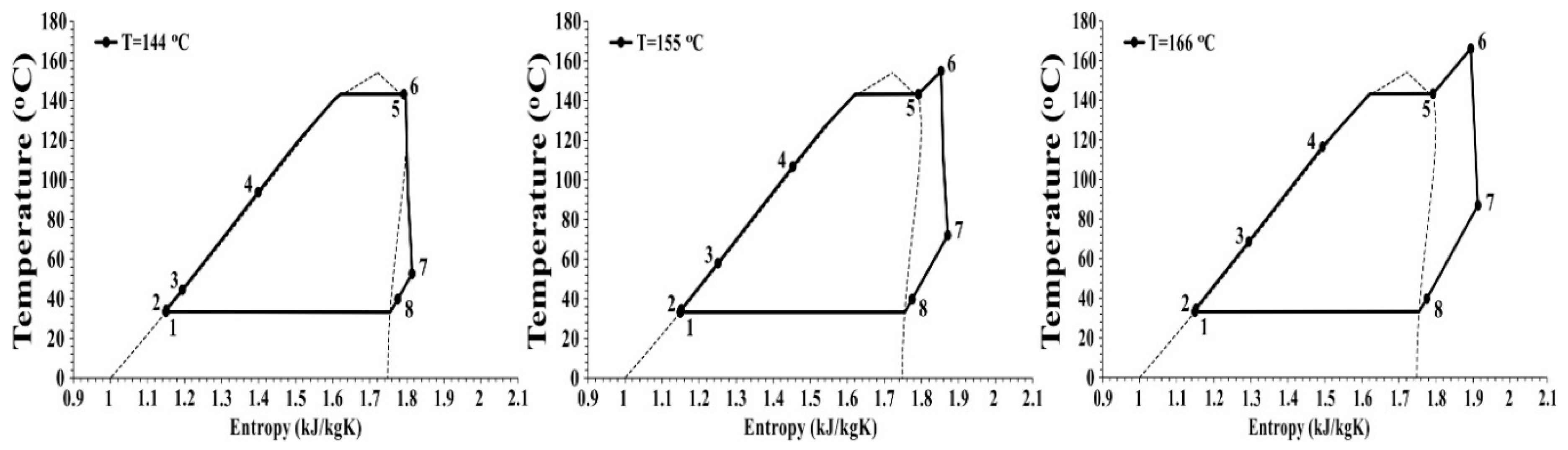
4.1. Subcritical rORC
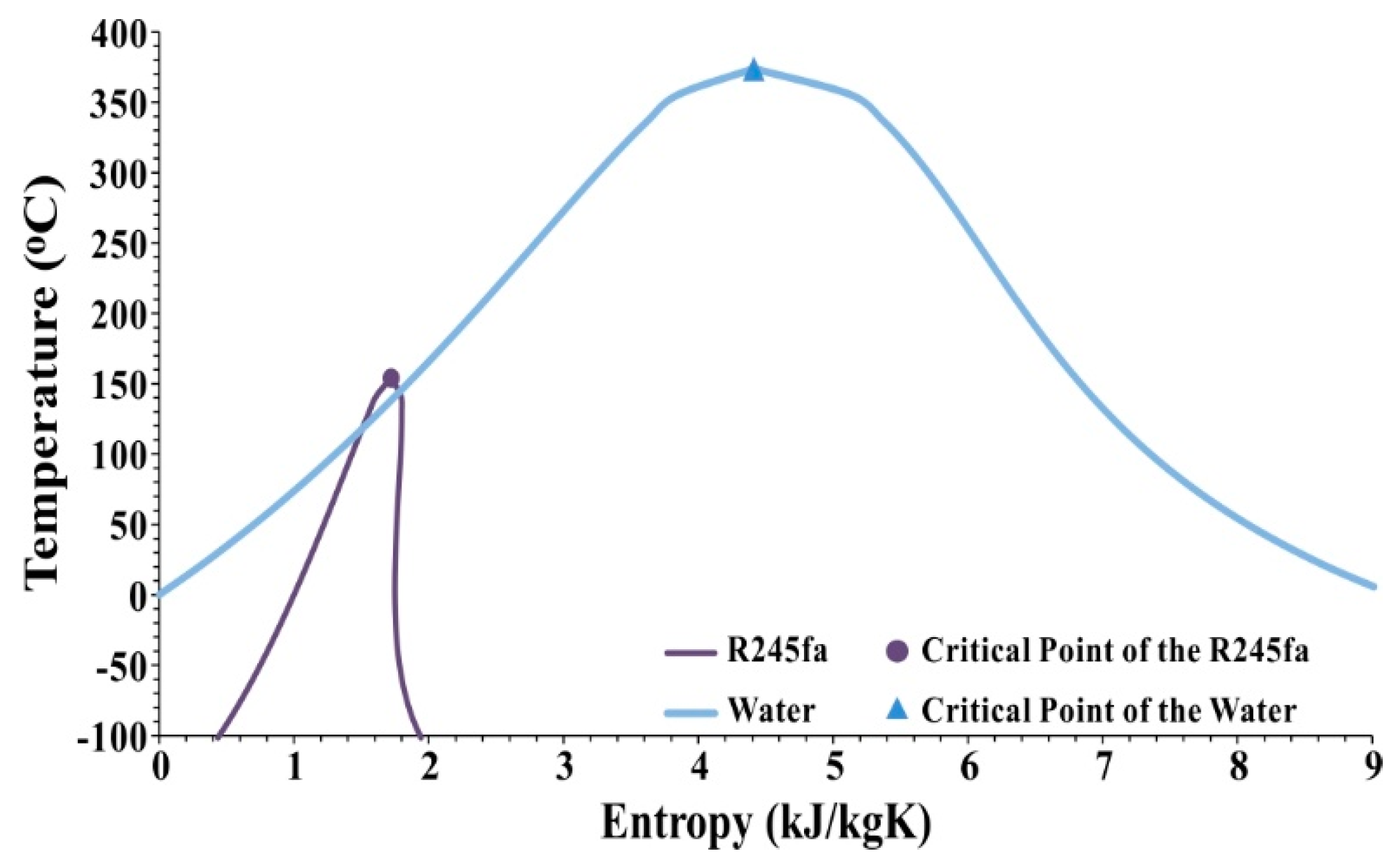
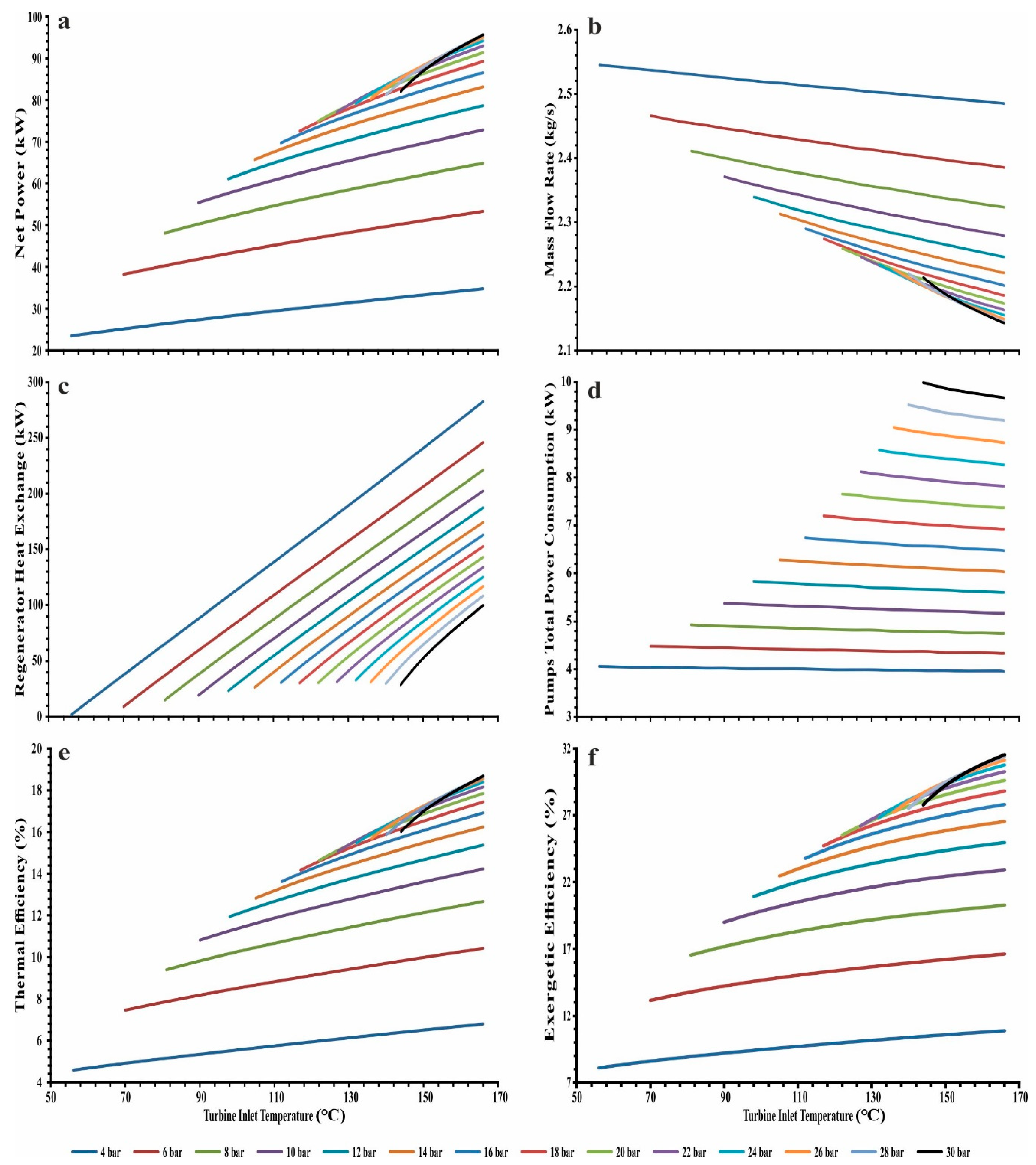
The turbine inlet pressure of a subcritical ORC is below the critical pressure. The subcritical rORC is designed for a varying pressure from 4 bar to 30 bar and a temperature from 56 °C to 166 °C. The saturated vapour temperature is selected as minimum turbine inlet temperature for each pressure value. During the simulation, the maximum temperature of the R245fa (166 °C) is chosen as the maximum turbine inlet temperature. Because chemical deteriorations occur above the maximum temperature of an organic-based hydrocarbon fluid [
60,
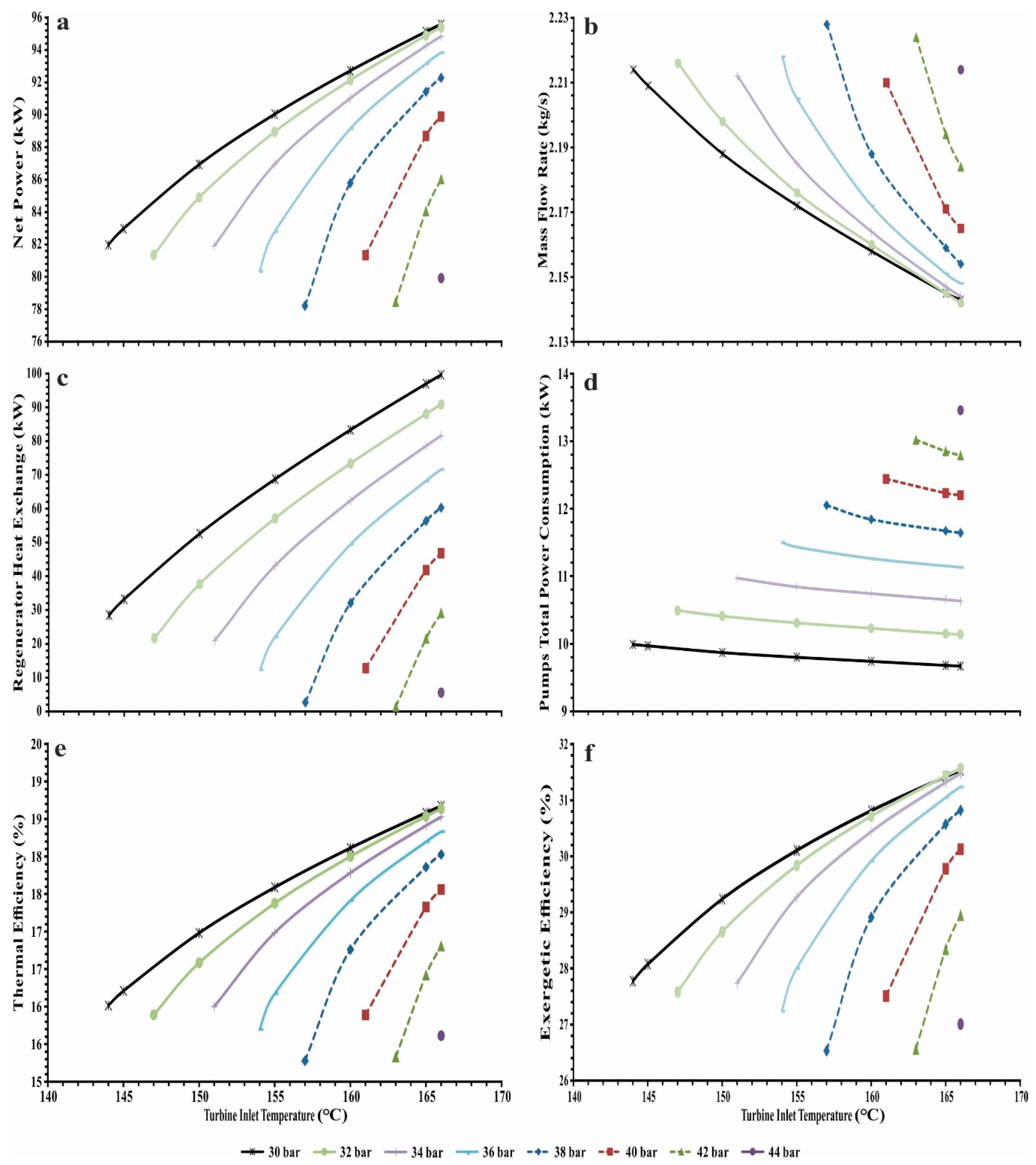
61]. The change in net power production, mass flow rate, exchanged heat in the regenerator, total pump power consumption, thermal efficiency and exergy efficiency according to varying turbine inlet temperature and pressure of the subcritical rORC is shown in
Figure 4.
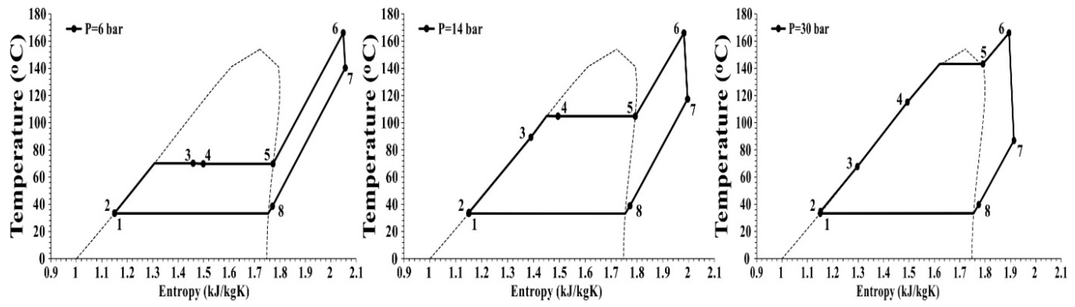
At constant turbine inlet pressure the net power production, exchanged heat in the regenerator, thermal and exergy efficiencies of the subcritical rORC consistently increase with increasing turbine inlet temperature, while the mass flow rate and total pump power consumption continuously decrease with increasing temperature. However, when the net power production, exchanged heat in the regenerator, thermal and exergy efficiencies are evaluated for varying pressure and temperature, two different trends are seen. In the first trend, up to turbine inlet pressure of 20 bar, the system performance shows a steady increase with increasing temperature at constant pressure.
In the second trend where the overlapping among the lines starts, between the turbine inlet pressure of 20 bar and 30 bar, the performance of the rORC becomes worse than the previous line at the starting temperature (saturated vapour temperature) and then the system performance improves rapidly with increasing temperature. In this trend, at constant pressure with rising temperature, there is a considerable performance increase between the starting and ending points. The main effect of the turbine inlet temperature and pressure combination is seen clearly in this trend. At high pressure, when the turbine inlet temperature is selected near to the saturation temperature, performance results of the system can be worse than the performance values at lower pressures. For instance, the net power production, thermal efficiency and exergetic efficiency of the subcritical rORC at 20 bar 145 °C is calculated as 84.55 kW, 16.52% and 28.13% while they are found as 82.97 kW, 16.21% and 28.07% at 30 bar and 145 °C, respectively. This occurs because of that, as seen in
Figure 5, at constant pressure the regenerated heat amount is increased with increasing temperature, which meant that the regenerator effectiveness rises with increasing turbine outlet temperature.
Moreover, as seen in
Figure 4c, the transferred heat amount in the regenerator decreases with rising turbine inlet pressure. The main reason for the decrease is that, at constant turbine inlet temperature, the turbine outlet temperature rises with increasing turbine inlet pressure (
Figure 6).
When all the results obtained from the system for varying turbine inlet temperature and pressure is evaluated together, it is clearly seen that the optimum working performance parameters like turbine inlet temperature and pressure should be selected precisely to get the maximum energy. The net power production, thermal and exergy efficiencies of the best performed rORC is calculated as 95.59 kW, 18.67% and 31.53% at turbine inlet temperature and pressure of 30 bar 166 °C, where the mass flow rate and total pump power consumption is found as 2.14 kg/s and 9.67 kW, respectively. There are many studies that support the results of the present paper. Chatzopoulou and Markides thermodynamically optimized an ORC-assisted internal combustion engine using R245fa. As a result of the optimization, thermal and exergy efficiencies of the ORC was calculated as 14% and 33%, respectively [
62]. In the present study, at the same turbine inlet temperature and pressure, the net power production per mass flow rate, thermal and exergy efficiencies were calculated as 36.25 kJ/kg, 15.78% and 27.17%. Zhang et al. performed the performance analysis of a rORC which used pure fluids and azeotropic mixtures as working fluids. As a result of the study, the thermal and exergy efficiencies of the R245fa used subcritical rORC is calculated as 10.54% and 22.85% at 12 bar 404 K, respectively [
63]. The present study shows similar thermal and exergetic efficiencies results of 13.73% and 23.38% at 12 bar 404 K. On the other hand, Xi et al. studied the parametric optimisation of a single-stage rORC under subcritical conditions and they found the net power production per mass flow rate, thermal and exergy efficiencies as 28.38 kJ/kg, 13.41% and 50.49% at 20 bar 135 °C, respectively [
64]. However, when the studies in literature are analysed together with those of the present paper, it is thought that the difference between thermal efficiency and exergy efficiency should not be this large.
4.2. Supercritical rORC
The turbine inlet pressure of a supercritical ORC is above the critical pressure. In order to describe the differences between subcritical and supercritical rORC and to reveal the cross-over from the subcritical to the supercritical state, the turbine inlet pressure of the rORC is started from a subcritical level (30 bar). Furthermore, the lowest turbine inlet temperature of the designed rORC at constant pressure is accepted as the saturation temperature. Since the chemical deterioration is seen in the chemical structure of the working fluid after the maximum temperature, the highest temperature of the system at constant pressure is assumed as 166 °C, which is equal to the maximal temperature of the R245fa [
60,
61]. The change in net power production, mass flow rate, exchanged heat in the regenerator, total pump power consumption, thermal efficiency and exergy efficiency according to varying turbine inlet temperature and pressure of the supercritical rORC is given in
Figure 7.
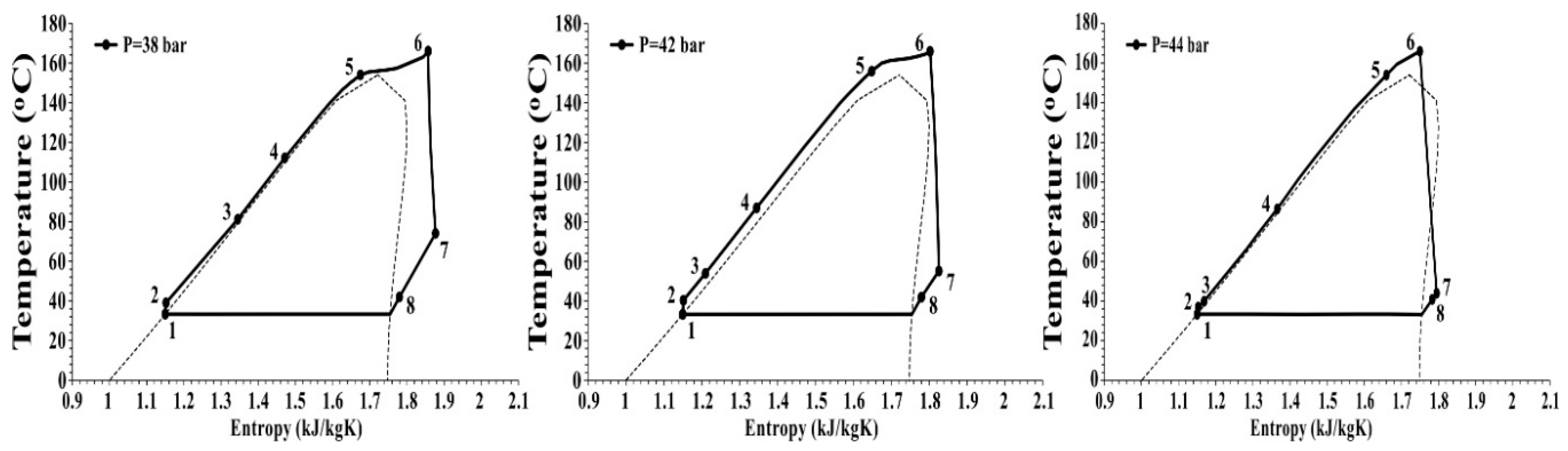
In
Figure 7, the performance of the subcritical and supercritical rORCs are given together. The rORC is working under subcritical conditions up to 36.51 bar turbine inlet pressure. Above 36.51 bar, the system starts to work under supercritical conditions. At constant pressure with increasing temperature, an increase is seen in the net power production, exchanged heat in the regenerator, thermal and exergy efficiencies while a decrease is seen the mass flow rate and total pump power consumption. However, the rORC shows opposite performance at a constant temperature with rising pressure. The best performing supercritical rORC cycle is obtained at a turbine inlet pressure and temperature of 38 bar and 166 °C.
The net power production, thermal and exergetic efficiencies of the supercritical rORC is calculated as 92.29 kW, 18.03% and 30.82% at 38 bar and 166 °C. Above the 38 bar turbine inlet pressure, the performance of the rORC is diminished. The main reason for the performance reduction above the 38 bar is that above this pressure the turbine outlet temperature is so near to the condenser outlet temperature which reduces the amount of heat transferred in the regenerator (
Figure 8).
Moreover, above 36 bar, the phase of the working fluid in the turbine becomes a saturated liquid and vapour mixture at low temperatures. Therefore, in the turbine, the liquid droplets occur which reduces the turbine performance and consequently decreases the performance of the rORC.
In many studies, similar results were obtained. Fernández et al. analysed a supercritical rORC using siloxanes as working fluid and as a result of the study, the thermal efficiency range varied from 15.1% to 15.9% for D4 type siloxanes, from 19.4% to 22% for MM type siloxanes [
65]. Although decomposition and deterioration in the chemical structure of the hydrocarbon-based working fluid is seen above the maximum temperature, Wang et al. studied a regenerative supercritical organic Rankine cycle for a turbine inlet temperature varying between 200 °C and 300 °C, which values are much higher than the maximum temperature of the R245fa [
66].
4.3. Effect of the Regenerator
This study aims to demonstrate the effect of the regenerator on the system performance as well as the parametric optimization of the rORC. Sometimes, small improvements applied to the system can give better performance results than radical changes [
67]. Therefore, in order to decide the best design and cycle condition, different types of organic Rankine cycle designs are studied in this paper and in the previous paper [
52]. In the concept of the present paper, a subcritical and supercritical rORC is designed and parametrically optimised. In the previous paper, the designing and parametric optimisation procedure are applied to a simple subcritical and supercritical ORC [
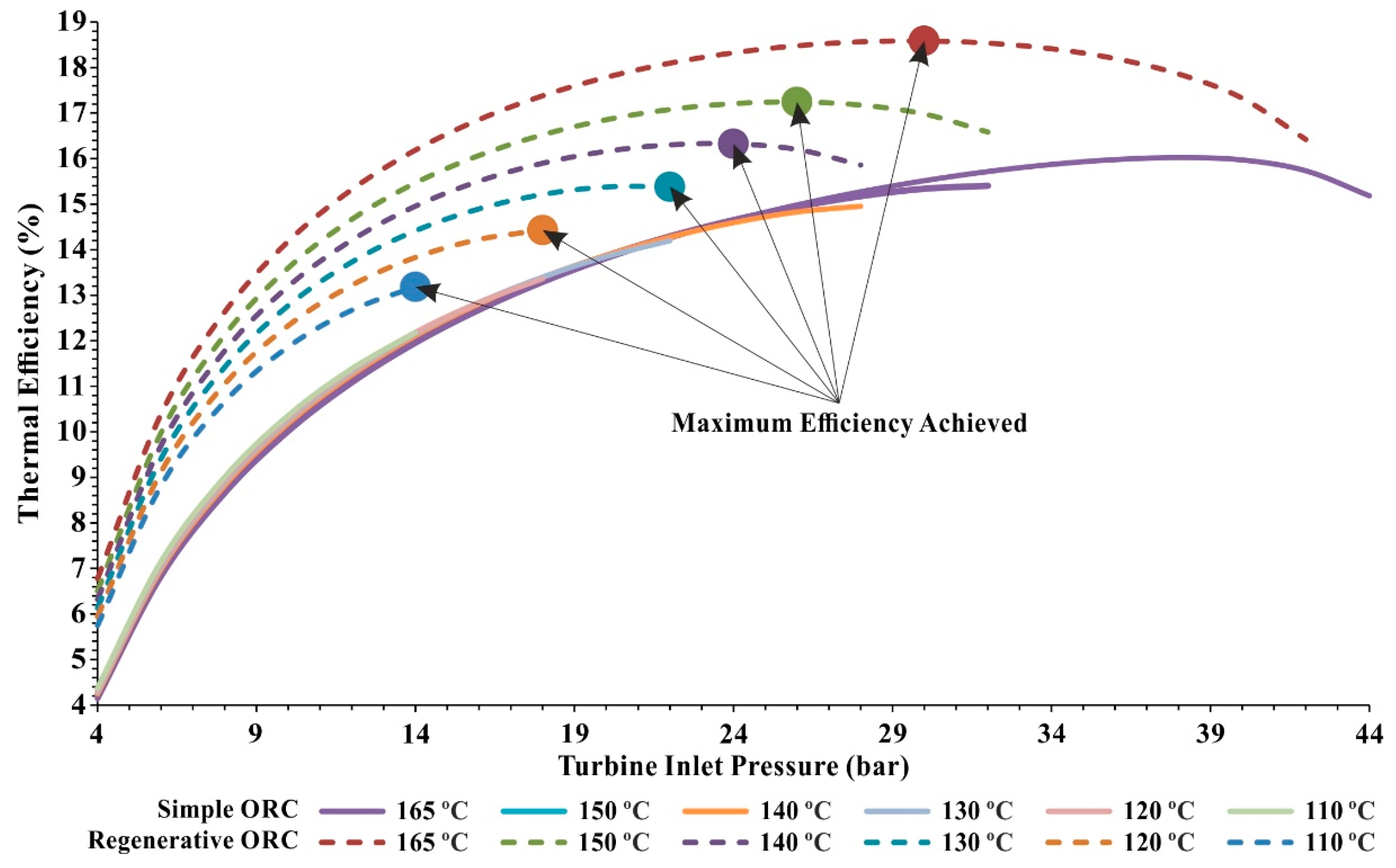
52]. Comparison of the thermal efficiencies of the simple ORC evaluated from the previous paper [
52] and rORC evaluated from the present paper is seen in
Figure 9. When the thermal efficiency of the rORC is compared with the thermal efficiency of the simple ORC, it is seen that thermal efficiency lines of the simple ORC are close to each other at constant pressure with rising temperature. This closeness among the lines of the simples ORC shows that turbine inlet pressure is more effective on cycle efficiency than the turbine inlet temperature. On the other hand, at constant pressure with rising temperature, there is a considerable difference among the thermal efficiency lines of the rORC.
Different types of ORC configurations (simple, regenerative, subcritical or supercritical) has many advantageous and disadvantageous to each other. For instance, the investment cost of a supercritical ORC is higher than that of a subcritical one [
12,
68] Moreover, compared with the subcritical ORC, the supercritical ORC has a higher turbine inlet pressure which affects the safety as well as investment cost [
69,
70]. When the ORC systems are compared in term of the regenerative and simple (non-regenerative) cycle, there are many studies which prove the superiority of the performance of rORC over simple ORC [
71,
72,
73,
74,
75,
76]. In this study, the best performed subcritical and supercritical rORC is evaluated at a turbine inlet temperature and pressure of 30 bar 166 °C and 38 bar, 166 °C, respectively. The net power production, thermal and exergetic efficiencies are calculated as 95.59 kW, 18.67% and 31.53% for the subcritical rORC and 92.29 kW, 18.03% and 30.82% for the supercritical rORC, respectively. In other respects, as a result of the calculations made for simple ORC in the previous paper, the net power production, thermal and exergetic efficiencies are calculated as 79.23 kW, 15.51% and 27.20% for the subcritical ORC and 81.52 kW, 15.93% and 27.76% for the supercritical ORC, respectively [
52]. As a conclusion, when cycle performance, investment cost, safety considered together, subcritical rORC can be selected as an optimum cycle rather than supercritical rORC, subcritical ORC and supercritical ORC.
In addition to all these considerations, a considerable limitation in turbine inlet temperature and pressure ranges is seen for rORC. When compared to the previous study, due to maximal temperature limitation and effect of the regenerator, the operating range of the rORC is even lower. This limitation is especially seen in the supercritical rORC results. In the previous study, the supercritical ORC runs for a wide range of turbine inlet temperatures and pressures. However, in the present study, a considerable decrease in working ranges are seen due to the regenerator. Therefore, at the turbine inlet pressure of 44 bar, the rORC is working only for one turbine inlet temperature point (166 °C).
4.4. Comparison of the Exergy Analysis of the Subcritical and Supercritical rORC
As a result of the parametric optimisation, the best performed cycle is evaluated at 30 bar 166 °C for the subcritical rORC and 38 bar 166 °C for the supercritical rORC. However, the maximal temperature of the selected working fluid (R245fa) is 166.85 °C which is almost equal to the turbine inlet temperature of the best-performing cycle. The working fluids of the rORC are organic-based hydrocarbon refrigerants. The chemical composition of the organic-based hydrocarbon refrigerants deteriorates above the maximum temperature [
60,
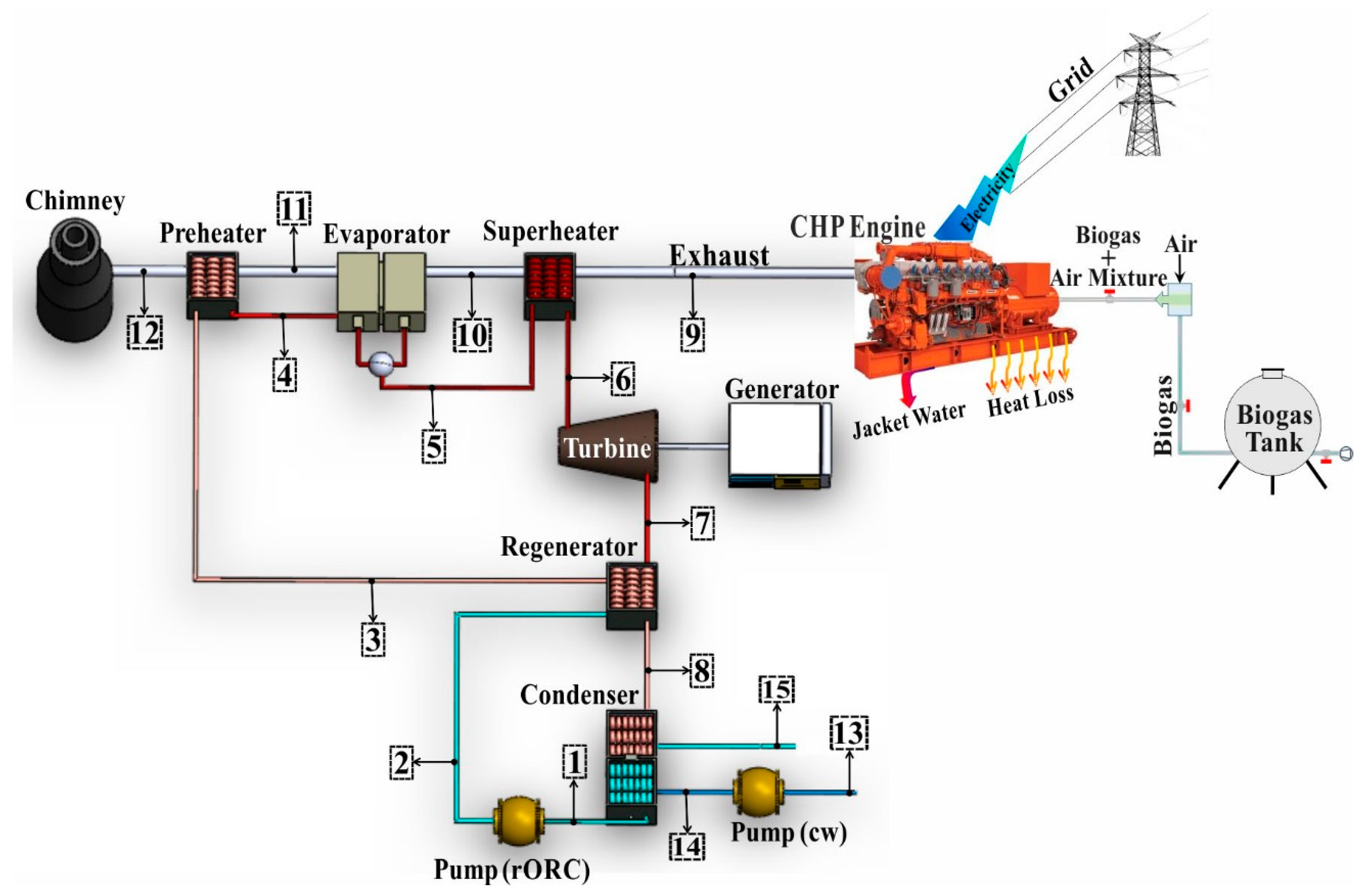
61]. Therefore, in order to protect the chemical structure of the fluid and keep in safe the working condition of the rORC, the best performing turbine inlet temperature is accepted as 165 °C for both subcritical and supercritical rORC. By considering this acceptance, the thermodynamic flow parameters recorded for the rORC pipes numbered in
Figure 2 at subcritical (30 bar 165 °C) and supercritical (38 bar 165 °C) conditions are given in
Table 5.
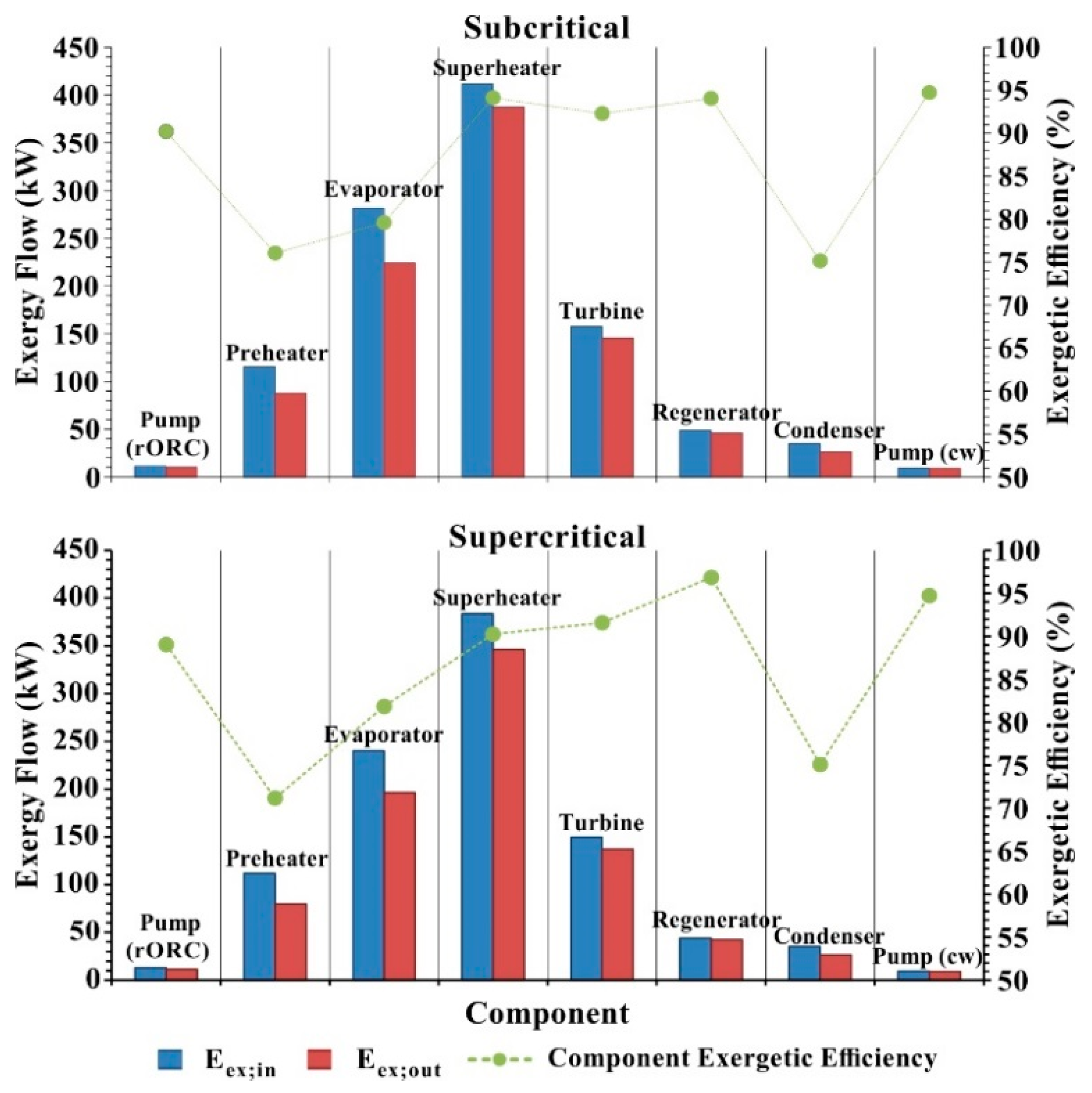
The data evaluated from the pipes are used to calculate the exergy flow and exergetic efficiency of each component. By using the equations given above, the exergy inlet, exergy outlet and exergetic efficiencies of each component of subcritical and supercritical rORC are found which are shown in
Figure 10.
The columns given in
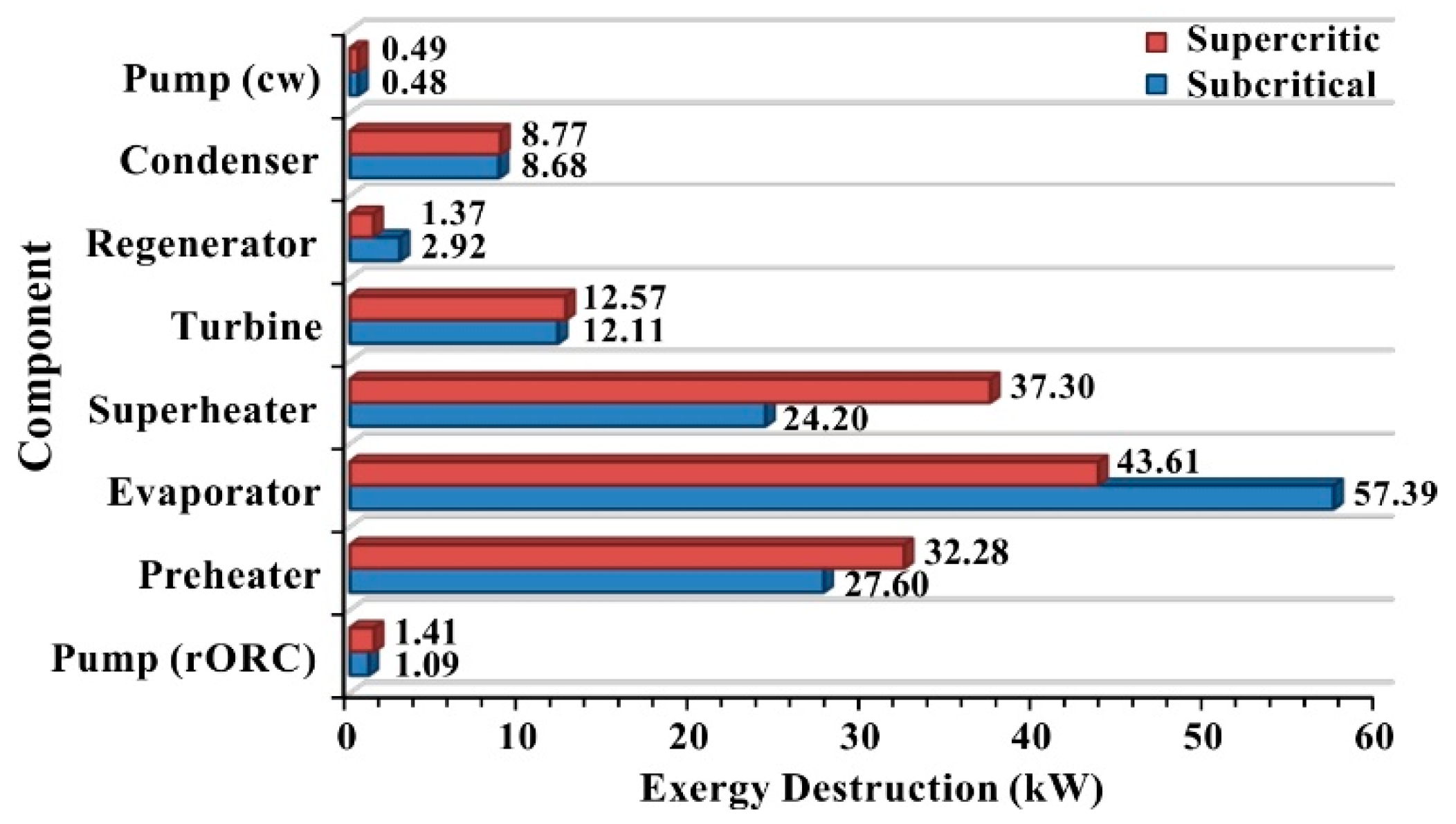
Figure 10 represent the exergy flow while the green line represents the component exergetic efficiency. For both subcritical and supercritical rORC, the exergy inlet and outlet are calculated in the superheater as maximum and in the pump (cw) as a minimum. As for component exergetic efficiency, the maximum and minimum component exergetic efficiency is found in the pump (cw) and condenser for the subcritical rORC and in the regenerator and preheater for the supercritical rORC, respectively. The maximum exergy inlet and exergy outlet are determined as 411.62 kW and 387.41 kW in the superheater component of the subcritical rORC and 383.66 kW and 346.36 kW in the superheater component of the supercritical rORC. The highest and lowest component exergetic efficiencies are found as 94.74% in the pump (cw) and 75.15% in the condenser for the subcritical rORC and 96.87% in the regenerator and 71.17% in preheater for the supercritical rORC. As seen from the general exergy balance equation given above, the differences between the inlet and outlet exergy equal to the exergy destruction. The exergy destruction rate of each component of the subcritical and supercritical rORC is given in
Figure 11. The maximum exergy destruction is calculated as 57.39 kW for subcritical rORC and 43.61 kW for supercritical rORC in the evaporator. The minimum exergy destruction is found as 0.48 kW for subcritical rORC and 0.49 kW for supercritical rORC in the pump (cw).
When the overall system parameters evaluated form the energetic and exergetic analysis of the rORC is considered together, the overall thermal and exergetic efficiencies are calculated as 19.17% and 32.41% for the subcritical rORC (at 30 bar, 165 °C) and 18.50% and 31.67% for the supercritical rORC (at 38 bar, 165 °C). Abam et al. compared the exergy-based performance analysis of a subcritical rORC for varying turbine inlet pressure range from 20 bar to 30 bar. As a result of the study, the maximum component exergy efficiency and component exergy destruction were calculated in evaporator and pump, respectively. Moreover, the overall exergy efficiency of the subcritical rORC using R245fa as working fluid is found between 30% and 35% [
77]. Energy and exergy-based analysis of a rORC assisted to a combined heat and power plant is studied by Anvari et al. They found that the component exergy destruction was maximum in evaporator and minimum in the pumps [
78]. The results of the studies are in line with the result of the present study.
5. Conclusions
In the concept of the present paper, firstly, a rORC was designed and parametrically optimised to evaluate the best-performing cycle condition to recover exhaust gas waste heat from a CHP engine. Then, to show the effect of regenerator on system performance, the parameters evaluated from the best performing subcritical and supercritical rORC was compared with the results of the previous paper which includes parametric optimisation of a simple subcritical and supercritical ORC. Finally, the exergetic analyses of the components and overall rORC was performed.
In the performance analysis of the subcritical rORC; at the constant turbine inlet pressure with rising temperature, an increase was observed in the net power production, exchanged heat in the regenerator, thermal and exergy efficiencies, while a continuous decrease was seen in the mass flow rate and the total pump power consumption. On the other hand, with varying turbine inlet temperature and pressure; the net power production, thermal and exergetic efficiencies continuously increased up to a turbine inlet pressure of 20 bar. Between the turbine inlet pressure of 20 bar and 30 bar, the net power production, thermal and exergy efficiencies became worse than the previous line at the starting temperature (saturated vapour temperature) and then the results rapidly increased with rising turbine inlet temperature. The main reason for dramatically increasing from worse results to better seen as the rapidly increasing regenerated heat amount. Between the turbine inlet pressure of 30 bar and 36 bar, the net power production, thermal and exergy efficiencies decreased with rising turbine inlet pressure. The reason for the performance decline is seen as the closeness of the turbine inlet temperature and saturated vapour temperature at this pressure ranges.
In the performance analysis of the supercritical rORC; the net power production, exchanged heat in the regenerator, thermal and exergy efficiencies showed rising results with increasing temperature at constant pressure, but, the performance of the rORC showed a decreasing result with rising pressure at constant temperature. The net power production, thermal and exergetic efficiencies are found as 92.29 kW, 18.03% and 30.82% for the best performing supercritical rORC at turbine inlet temperature and pressure of 38 bar, 166 °C. In the case of the subcritical rORC, the net power production, thermal and exergetic efficiencies are calculated as 95.59 kW, 18.67% and 31.53% for the best performing subcritical rORC at a turbine inlet temperature and pressure of 30 bar 166 °C. When the result of the previous study is considered [
52], it is clearly seen that the subcritical rORC shows the best performance, so by using the subcritical rORC, the disadvantages of the using simple ORC (low performance) and supercritical cycle (safety, investment) can be eliminated, while improving system performance.
Despite the positive system performance results, the use of regenerators in the ORC creates restrictive effects on working pressure and temperature intervals, especially in supercritical conditions. At constant pressure, the turbine inlet temperature range of the rORC is narrower than the simple ORC. Moreover, unlike the simple ORC, the upper pressure of the rORC is also limited. While the simple ORC can operate in temperature between 155 °C and 166 °C at 46 bar turbine inlet pressure, the rORC could not work at 46 bar turbine inlet pressure due to the maximal temperature limitation and effect of the regenerator. The rORC can only be worked a turbine inlet pressure of 44 bar where the rORC is only working at a turbine inlet temperature of 166 °C. In spite of the restrictive effect of the regenerator, the rORC systems showed better performance results than simple ORC for both subcritical and supercritical conditions.
As seen from
Figure 9, the thermal efficiency reached its maximum value at certain pressures while the increase in the thermal efficiency continued with the pressure increase at the constant temperature. After the maximum point where the thermal efficiency was the highest, the increase in the pressure caused a decrease in the thermal efficiency. For this reason, considering the turbine inlet pressures where maximum efficiency is obtained depending on the temperature has critical importance in regenerator usage.
In addition, the exergetic analysis of the best performing subcritical and supercritical rORC was performed and the results were compared with each other as well as a simple ORC. Just like the simple ORC, the highest exergy destruction was seen in the evaporator. The overall thermal and exergetic efficiencies are calculated as 19.17% and 32.41% for the subcritical rORC and 18.50% and 31.67% for the supercritical rORC. On the other hand, in the previous paper, the thermal and exergetic efficiencies of the simple ORC was found as 15.51% and 27.20% for the best performing subcritical condition, 15.93% and 27.76% for the best performing supercritical condition [
52]. When the results of the present and previous paper compared, it is clearly seen that the subcritical regenerative organic Rankine cycle (rORC) has the best performance.


