Article

Multi-Agent System with Plug and Play Feature for Distributed Secondary Control in Microgrid—Controller and Power Hardware-in-the-Loop Implementation

1
Univ. Grenoble Alpes, CNRS, Grenoble INP, G2Elab, F-38000 Grenoble, France
2
Institute for Energy and Environment, Electronic and Electrical Engineering Department, University of Strathclyde, Glasgow G1 1XW, UK
3
Alternative Energies and Atomic Energy Commission (CEA), National Institute for Solar Energy (INES), F-73375 Le Bourget-du-Lac, France
4
Austrian Institute of Technology, 1210 Vienna, Austria
5
Department of Electrical Engineering, University of Science and Technology—The University of Danang, Danang 550000, Vietnam
*
Author to whom correspondence should be addressed.
Energies 2018, 11(12), 3253; https://doi.org/10.3390/en11123253
Submission received: 26 October 2018 / Revised: 7 November 2018 / Accepted: 16 November 2018 / Published: 22 November 2018
(This article belongs to the Special Issue Methods and Concepts for Designing and Validating Smart Grid Systems)

Abstract

:
Distributed control and optimization strategies are a promising alternative approach to centralized control within microgrids. In this paper, a multi-agent system is developed to deal with the distributed secondary control of islanded microgrids. Two main challenges are identified in the coordination of a microgrid: (i) interoperability among equipment from different vendors; and (ii) online re-configuration of the network in the case of alteration of topology. To cope with these challenges, the agents are designed to communicate with physical devices via the industrial standard IEC 61850 and incorporate a plug and play feature. This allows interoperability within a microgrid at agent layer as well as allows for online re-configuration upon topology alteration. A test case of distributed frequency control of islanded microgrid with various scenarios was conducted to validate the operation of proposed approach under controller and power hardware-in-the-loop environment, comprising prototypical hardware agent systems and realistic communications network.

1. Introduction

Microgrids (MGs) are considered as the major component of the future power system to deal with the proliferation of distributed generators (DGs) in low and medium voltage grids. In general, a MG is a system integrated by DGs, controllable and non-controllable loads, energy storage systems (ESS) and control and communication infrastructure. The MG can operate in islanded mode or grid-connected mode [1]. By moving the generation closer to loads, MGs aid in reducing power transmission losses. MGs also improve the reliability of the system with the ability to switch to islanded mode during system disturbances and faults.
MGs introduce many advantages to both utility and consumers. However, control and management of MGs induce significant challenges in term of coordination and aggregation. Centralized schemes, which are common in conventional power systems, may no longer be suitable for significantly larger numbers of DG units due to many reasons [2], e.g., excessive computation in the central unit due to numerous controllable loads and generators, reliability and security of the central controller, frequent mutation of grid due to installation of new DGs and loads, unwillingness to share data of participant actors, etc. Decentralized strategies are highly scalable and robust because controllers only need local information and ignore coordination with others. However, the system controlled in decentralized way can hardly reach network-wide optimum operation. Distributed approach is considered as the best alternative for the control and management of the next generation of power systems. In this approach, the central unit is eliminated and local controllers coordinate with nearby units to reach global optima. The main advantage of the distributed approach [2,3,4] is that the MGs can avoid system failure because the single central unit for controlling whole system is neglected. Moreover, it presents enhanced cyber-security and reduced communication distances. Furthermore, with the ability to perform in parallel, the computational load can be shared and condensed significantly. Finally, the privacy of sensitive information of loads of DERs could be inherited in the global operation.
Multi-agent system (MAS) is an advanced technology that has been recently applied in various areas of science and engineering, including smart grids. In the power systems domain, agent-based approaches have been applied in a wide range of applications such as load shedding, secondary control or optimal power flow [5,6,7]. Agent with properties as autonomous, social, reactive and proactive [7] are ideally suitable for distributed control implementation. The focus of this paper is the distributed secondary frequency control strategy for islanded MGs to restore grid network to normal state under various disturbances using MAS. Distributed control algorithms with an upper layer of agents have been presented recently in refs. [7,8]. In refs. [9,10,11,12], novel distributed algorithms where proposed and validated using pure power systems simulation tools. Some other works have utilized MAS runtime environments (such as Java Agent Development Framework (JADE)) to implement the distributed control system [13,14].
The interactions between entities (controllers, agents, devices, etc.) in MGs can lead to unexpected behaviors, thus advanced platforms for testing are required to evaluate the performance of MGs before the real deployment. The Hardware-in-the-loop (HIL) is an effective methodology to investigate MGs [15,16,17]. HIL enhances the validation of components in power systems by conducting controller Hardware-in-the-loop (CHIL) and power Hardware-in-the-loop (PHIL) [18]. CHIL is performed to validate protection and controller devices. In the meanwhile, PHIL is used to validate the operation of power devices as well as the dynamic interactions between them. The HIL implementation has been used in refs. [6,19,20] for the investigation in distributed control in MGs. However, the combination of CHIL and PHIL or the realistic communication environment is rarely reported.
In distributed control, communication plays an important role as system performance (e.g., local optimization and global convergence time) depends heavily on the information exchange among agents [21]. In order to ensure seamless communications in MAS, it is required that the system possesses and maintains a high level of inter-agent interoperability. Interoperability allows the network to seamlessly and autonomously integrate all components of power, distribution, management, and communication while minimizing human intervention. It has a direct impact on the cost of installation and integration and also introduces the ability to easily connect and integrate new components and systems. It allows the substitution/improvement of a component in the network without any problem to the overall operation of the integrated system [22]. It is however not an easy task due to the existence of a variety of vendors and communication interfaces in the framework of micro-grid. Standards or regulations can be used to bridge the gap but are not necessarily sufficient to ensure interoperability. In some cases, systems implementing the same standard may fail to interoperate because of the variability in the practical implementations.
Interoperability can be considered in several evaluation models and in terms of different technical and conceptual levels (e.g., semantic, syntactic, dynamic and physical) [23]. As in the Smart Grid Interoperability Maturity Model (SGIMM) [24], ultimate goal of interoperability is the concept of “plug-and-play”: the system is able to configure and integrate a component into the system by simply plugging it in. An automatic process determines the nature of the connected component to properly configure and operate. Achieving plug-and-play is not easy, and in the particular context of distributed control in micro-grid with MAS, several important challenges are highlighted:
  • Firstly, in MGs, infrastructure may be supplied by different vendors and may be compliant to different protocols. Agents are required to be able to transfer data with local controllers and measurement system through various standardized or commercialized industrial protocols, while on the other hand, has to comply with the inter-agent communication protocols.
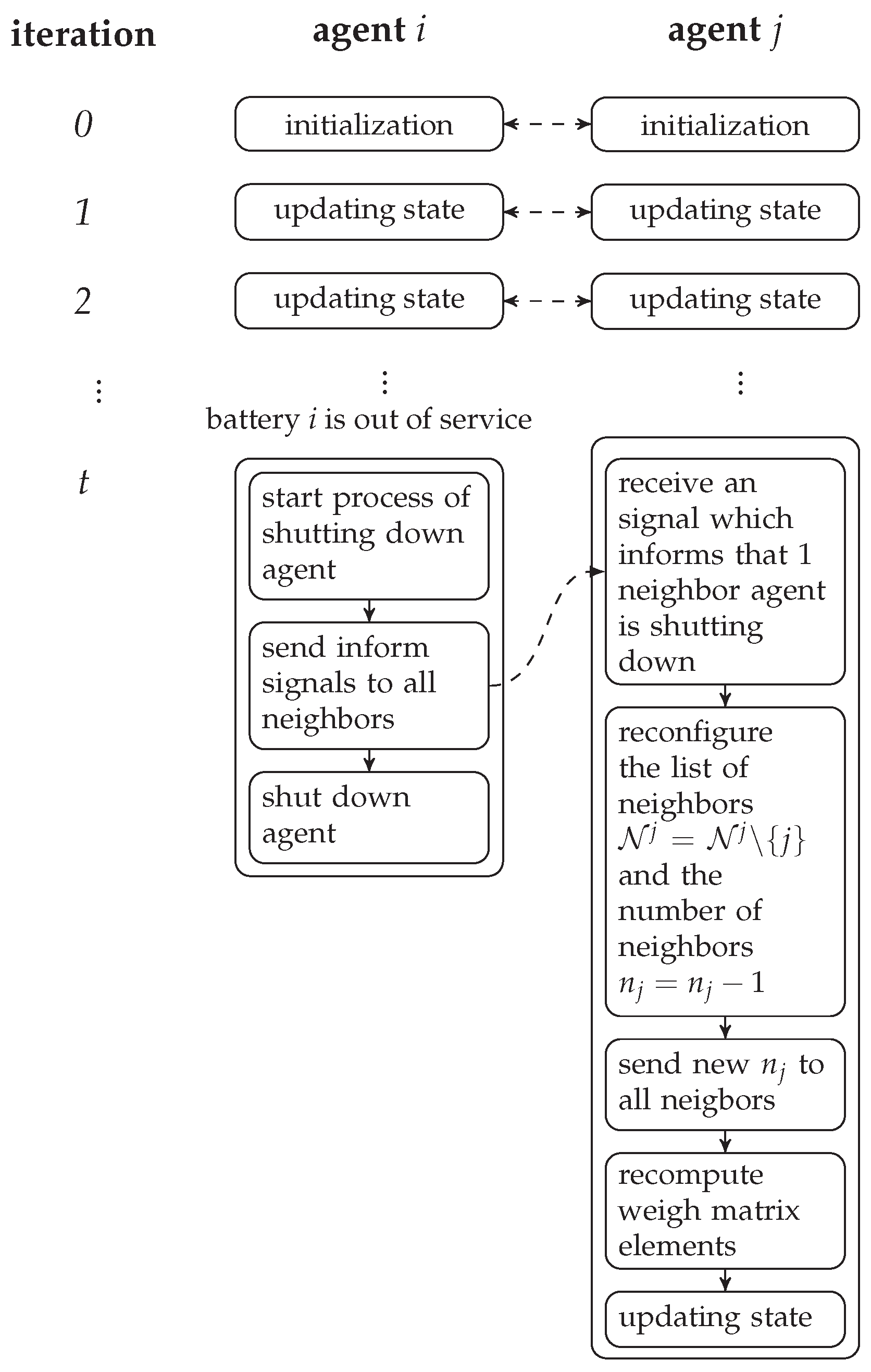
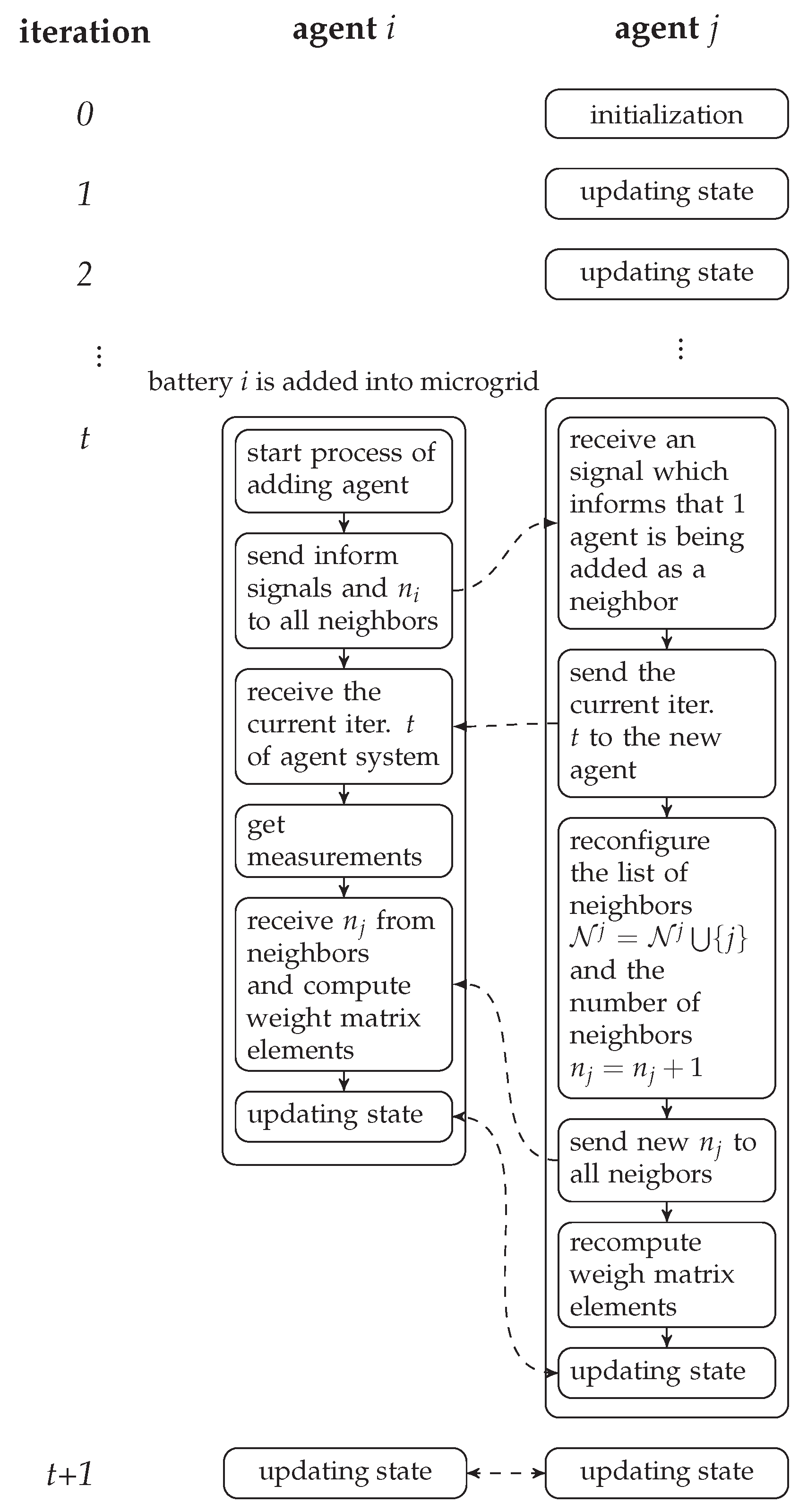
  • Secondly, in distribution network of MG, the structure of grid and the total capacity of ESSs may change/be upgraded progressively along with the increase of loads and renewable energy sources. Furthermore, ESS is an element which requires regular maintenance and replacement. The corresponding agent has to be activated or deactivated accordingly to the state of the ESS. The local control algorithm (intra-agent) needs to be flexible enough to adapt to this frequent alteration of structure and capacity without major re-configuration.
  • Not only at local level, the alteration of topology is also a critical obstacle that needs to be solved to achieve "Plug and Play" capacity at system level. The micro-grid operation is based on the consensus processes of the agents which tries to find a global solution based on limited information acquired from the neighbourhood. Consensus algorithms are introduced mathematically and often adapted to a certain network topology. Therefore, the integration or removal of an agent in the network (or alteration of topology) requires a throughout re-configuration or adaptation of the entire network.
  • Last but not least, the asynchronous interaction (inter-agent) under influence of various type of uncertainties in a real communications network is much more complex and is not yet covered in the mathematical model. The performance of the real system may be derived from the theoretical one if this aspect is not considered during the design and validation process. However, in aforementioned research, the communication network is typically ignored. In ref. [25], the data transfer latency is considered, as deterministic time delays which does not accurately reflect realistic communications networks. Furthermore, the design of agents and the interactions among the agents as well as with controllers and devices were ambiguous and unspecific.
The above challenges are tackled in this paper. Particularly, we propose a method to implement interoperability within a MG with plug and play feature at the agent layer of distributed control scheme.The main contributions of this paper are twofold:
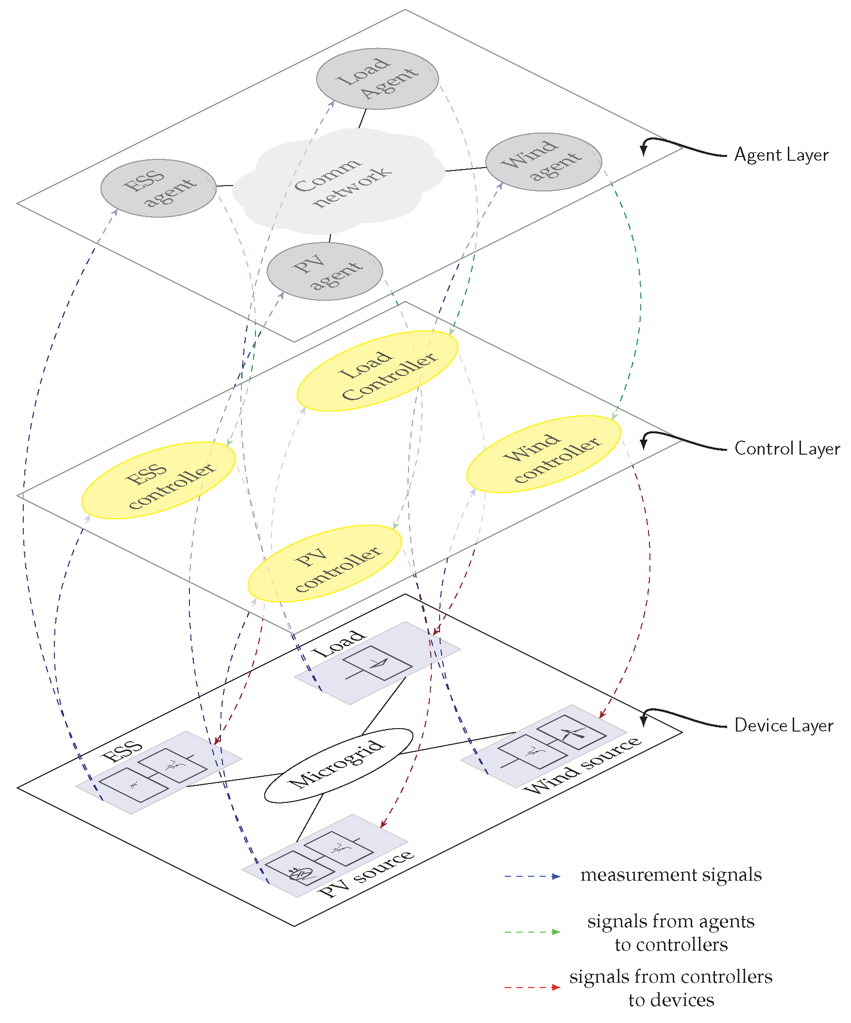
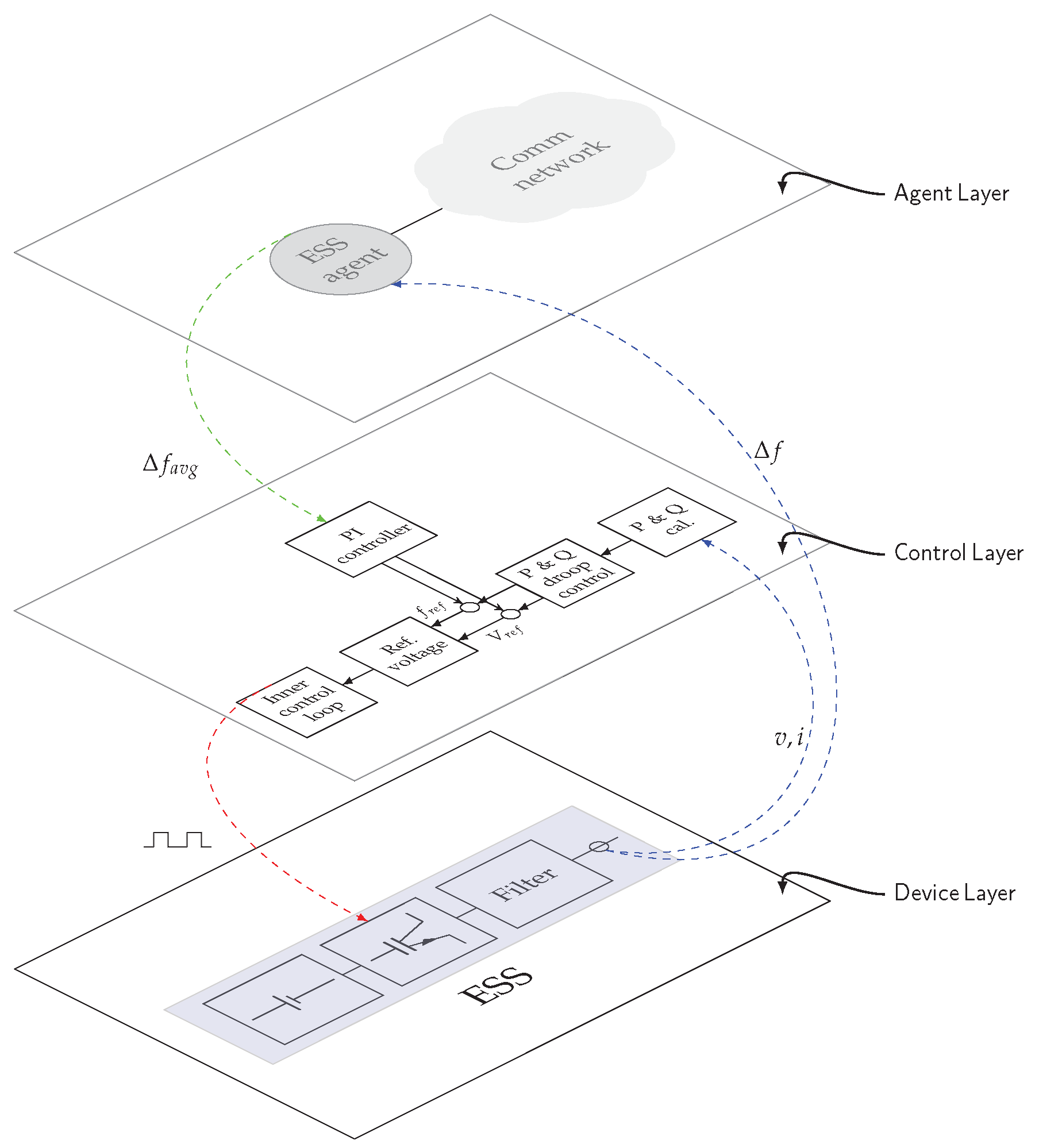
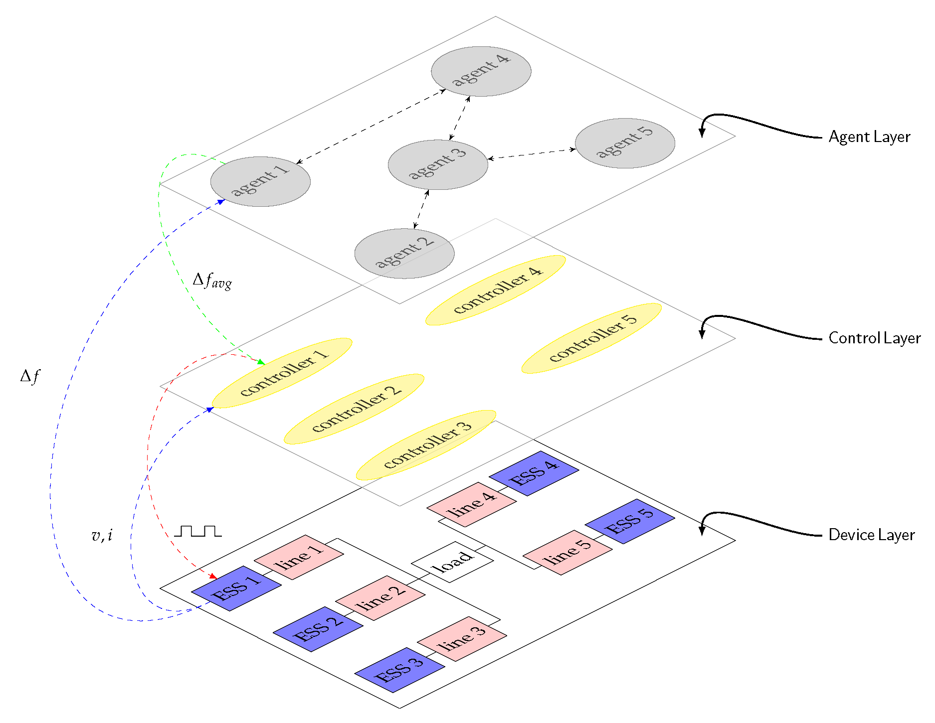
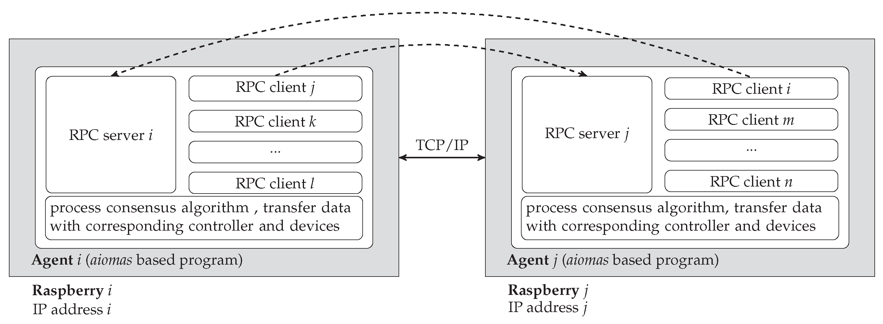
  • We develop a multi-agent system with “plug and play” capacity for distributed secondary control of frequency in islanded MGs. Firstly, a multi-layer structure is proposed to describe thoroughly the MG system operating with agents. The structure consists of three layers: Device layer, Control layer and Agent layer. The agent, which is an autonomous program with server/client structure, is designed to process an average consensus algorithm and send proper signal to inverter controller in a distributed scheme. The agent is also equipped with the ability of collecting and broadcasting messages via the industrial protocol IEC 61850. The “Plug and Play” capacity is realized at the agent layer, as the system will automatically adapt to the alteration of topology (integration of new agent or removal of an agent) and react accordingly to maintain seamless operation.
  • The proposed distributed secondary control is implemented in a laboratory platform based on the propose in [18] with controller and power-hardware-in-the-loop (C/PHIL) setup, incorporating realistic communications network with the impact of uncertainties considered. The performance of system under realistic condition shows that the agents are able to resist to disturbances and to self-configure under alteration of grid topology.
The paper is organized as following: Section 2 presents layer structure of a MG and average consensus algorithm. Section 3 describes the design of agents with plug-and-play feature operating as highest layer in the structure. Section 4 provides a laboratory platform with controller and power HIL setup to simulate a test case autonomous MG. A testing procedure and experimental results is also presented to validate the operation of agent system in a physical communication network. Section 5 concludes the paper while also highlighting some aspects worthy of consideration in future.

2. MAS Based Multi-Layer Architecture for Distributed Secondary Control in MG

The hierarchical structure, which is comprised of primary, secondary and tertiary level, is commonly used to control in MG [26,27,28]. The primary control level is used to stabilize frequency and voltage when disturbances occur by using only local measurements. The system in this control level has a fast response to reach the steady-state. However, there are deviations of frequency and voltage compared with the nominal values. The secondary control with global information is implemented to restore the frequency and voltage. At the top layer, the power flow to the main grid and optimized operation within grids is managed in the tertiary control level. This paper deals with the problem of secondary control in MG. In particular, we propose a three layer structure based on MAS for distributed secondary control in MG.
The architecture consists of three layers: Device layer containing the physical components and electrical connections, Control layer corresponding to alterations in the system operation, and providing control signals to the Device layer and finally Agent layer which receives measurements from corresponding devices, communicates, calculates and then returns proper signals to controllers. This architecture shows distinctly the relationship between agents and power system components while emphasizes on the communications network, which introduces increasingly important impact to the modern grid. Figure 1 illustrates the three-layer structure, where devices, controllers and agents are shown.
Depending upon the objective and requirement of the device under control, the controller in Control layer either needs information from its agent and device or only its device. For instance, MPPT controller for PV source or primary control for inverter require local measurements from Device layer. However, with the secondary and tertiary controls of inverters, the additional signals from Agent layer are mandatory. In this paper, Control layer comprises controllers of inverters operating in parallel as grid-forming sources. The parallel configuration of voltage source inverters (VSIs) allows connection of multiple VSIs to form a MG thus facilitating the scalability and improving the redundancy and reliability of system. The control of each inverter is responsible for sharing the total load demand according to the rated power and resisting the instability of frequency and voltage in MGs. When a disturbance in the MG happens, the primary control of DGs will active immediately and the system is stabilized. Then, agents in Agent layer will send signals to compensate any errors with respect to the nominal condition through the secondary control. The local controller of DG in Control layer includes primary and secondary control level in the hierarchical control structure. The primary control adjusts the references of frequency and voltage to provide to the inner control loop of the inverter. The secondary control is conducted to fix the frequency and voltage to their nominal values after any changing of the system. This paper will focus only on controlling frequency, the proportional integral (PI) controller is used to deal with the steady-state error.
Classical approaches employ the MG’s central controller which receives Δ f from the measurement of a single point of the grid. The setpoint of secondary control unit is then distributed to local controllers of primary control. However in the distributed control manner, this centralized unit is eliminated. In our proposal, each local controller corresponds to an agent. The measurement devices are required to provide local frequency deviation to the connected agent which communicates with others to return the global Δ f . An agent-based consensus algorithm is applied in the Agent layer and the processes in all agents converge at a same consensus value after a number of iterations. This consensus value is also the average frequency deviation transferred to PI controller.
In the proposed distributed frequency control system, each agent needs only local information but could return global results by using the average consensus algorithm. The algorithm also ensures that the signals are sent to the local controllers concurrently and those signals have the identical values as in the case of the centralized strategy.
A consensus algorithm is an interaction rule for a specific objective. The rule describes the information exchange between a entity and its neighbors in the communication network. It is assumed that each agent receives an input value at initial. The average consensus problem is the distributed computational problem of finding the average of the set of initial values by using only local and adjacent information. Consider a network with N nodes, the initial value at node i is x i ( 0 ) R . Node i only communicate with node j N i in a constraint network. The goal of the algorithm is: firstly, each node compute the average of initial values, 1 N i = 1 N x i ( 0 ) and secondly, all nodes reach consensus on this value at the same time.
lim t x i ( t ) = 1 N i = 1 N x i ( 0 ) i V
Equation (2) introduces a standard algorithm to solve the average consensus problem following the iteration update.
x i ( t + 1 ) = j = 1 N W i , j x j ( t ) i = 1 , , N
where t N are the iteration steps and W R N × N is the weight matrix. Each node uses only local and neighborhood information, hence, W i , j = 0 if j N i and j i . To simplify the expression of the algorithm, let us define the column vector of x i ( t )
X ( t ) = x 1 ( t ) x 2 ( t ) x N ( t )
Then Equation (2) can be rewritten as:
X ( t + 1 ) = W X ( t )
Assuming that consensus state is achieved at iteration t 0 , from Equation (3) we can imply that X ( t 0 ) = W t 0 x ( 0 ) . The necessary and sufficient condition for the convergence is:
lim t W t = 11 T N
where 1 is the vector consisting of only ones. There exists various ways to determine the weight matrix. In this work, we choose the Metropolis rule [29] because of its stability, adaptability to topology changes and near-optimal performance. The element of weight matrix is found as Equation (5)
w i j = 1 m a x ( n i + 1 , n j + 1 ) , if i N j 0 , if i N j 1 i N j a i j , if i = j
where n i = | N i | , w i j [ 0 , 1 ] .

3. Design of Agent with the Plug and Play Feature

In this section, we introduce the design of agents with plug and play feature for distributed secondary control in an islanded MG with multiple grid-forming inverters. The MG includes a number of ESSs with power electric inverter interface operated in parallel. All of the ESSs participate in regulating frequency and voltage to keep the grid in the steady state. In this work, we focus on frequency control. Due to multi-master strategy, the coordination between inverters in the grid is mandatory. The operation of an ESS, which is connected to grid through an inverter based interface, is separated into three parts in the proposed layer structure, as described in Figure 2. The PI controllers of inverters requires setpoints from agents to recover the frequency to normal once disturbances occur in the MG. The agent in this work is designed to implement the average consensus algorithm presented in previous section. The process of the algorithm is iterative. The state in initial iteration of an agent is the input of the agent, which is frequency deviation sensed locally from the device layer. Agent output, serving as feedback to the controller, is the average of inputs of all agents in the system. The output is collected after a specific number of iterations.
The iterative process in an agent is described in Algorithm 1. The agent conducts consecutive consensus loop. A loop is begun from Iteration 0 when the agent receives the measurement from devices and is finished at Iteration t 0 . Upon reaching the consensus state at Iteration t 0 , the agent sends its final state to the corresponding controller and immediately jumps to a new loop at Iteration 0 again.
Algorithm 1 The average consensus process in Agent i.
1:
t = 0                                 ▹ begin a loop at initial iteration
2:
N i N 0 i                                ▹ list of neighborhood agents
3:
n i = | N 0 i |                                  ▹ number of neighbors
4:
x i x 0 i    ▹ obtain initial state from Device layer, this state is value of frequency deviation measured locally at node i
5:
distribute the initial value and number of neighbors to all neighbors
6:
collect the initial value and number of neighbors from neighbor agents x j , n j j N i
7:
w i j = 1 m a x ( n i + 1 , n j + 1 ) , if i N j 1 i N j a i j , if i = j   ▹ calculate elements of weight matrix involved in Agent i and its neighbors using Metropolis rule
8:
collect the initial value of neighbors
9:
t = t + 1                                   ▹ move to Iteration 1
10:
while t < t 0 do            ▹ t 0 is the number of iteration needed to reach the consensus state
11:
     x i ( t ) = j N i w i j x j ( t 1 )                    ▹ update the state at Iteration t
12:
    distribute the updated state at Iteration t to all neighbors
13:
    collect the state of all neighbors at Iteration t
14:
     t = t + 1                               ▹ move to next iteration
15:
return x i ( t 0 )         ▹ consensus value which is the average of measured frequency deviation
16:
send the consensus value to Control layer (to PI controller)            ▹ finish the current loop
17:
redo from step 1                               ▹ start a new loop
Intuitively, what happens in agents is separated into three phases:
  • Initialization phase: Each agent receives initial state which is its local frequency deviation. Data are transferred from Device layer to Agent layer.
  • Updating state phase: States of next iterations in each agent are updated using the agent current state and neighbors’ states following Metropolis rule. An agent will move from Iteration t to Iteration t + 1 if and only if it collects information from all neighbors at Iteration t. Data are then transferred internally within the Agent layer.
  • Returning value phase: At a specific iteration, all agents finish consensus process loop and send the same average value of frequency deviation to controllers. Data are transferred from Agent layer to Control layer.
The calculation for each iteration relies on information being received from neighbors. The consensus processes in agents are therefore almost at the same iteration (not always at the same iteration due to minor differences introduced by time taken to exchange data amongst the agents). It can be imagined that all agents are on a line and all elements in this line march ahead from an iteration to the next iteration together in a "lock-step" manner. If an issue occurs with any element, this line will stop moving on until the issue is fixed.
In MGs, the topology and the total capacity may change subject to the increase in load and fluctuations in renewable energy sources. The global consensus based operation of the MG has to be capable of adapting to this frequent alteration of structure and capacity without major re-configuration. In our research, we design the agent system with the capability of plug and play operation, i.e., the network and the algorithm need to automatically detect and adapt to addition and/or removal of agents.
Figure 3 describes the logic implemented within agents when Agent i is shut down owing to its corresponding ESS i being out of service. We also consider agents who are connected with Agent i. Agent j is one of the neighbors of Agent i. When obtaining signal from Device layer and knowing that the ESS it handles was tripped out, Agent i triggers its process of shutting down. It sends signals to all neighbors to inform its status before stopping. In term of Agent j (as well as other neighbors of Agent i), when receiving the alert from Agent i at Iteration t, it will pause the process of updating state and start the reconfiguration process. Because Agent j lost one neighbor, the neighbors of Agent j also have to recompute the weight matrix elements. The agent system are paused at Iteration t until all involved agents finish modifying and return to the updating process.
Figure 4 presents the mechanism of an Agent i and its neighbors when the Agent i is added into the operating multi-agent system (an ESS is installed to MG). The unknown integration of Agent i in the agent network may cause the disturbance to the involved agents. Agent j is one neighbor of Agent i. The task of all involved agents in this case is more complicated because Agent i has no information about current iteration of agent system that may break the synchronization and accuracy in computation of agents. We propose a way to overcome this challenge as follows: Once Agent i is notified that its corresponding ESS (ESS i) is connected to the MG, it will inform its neighbors about its appearance in the agent system and require the current Iteration t of system in reverse. Simultaneously, Agent i takes parameters from its neighbors to compute weight matrix elements. Neighbor j deals with this scenario in the similar way when Agent i is removed. An additional step in this case is only that Agent j broadcasts the current iteration to Agent i. The multi-agent system after that moving to next iterations and operating normally.
This proposal minimizes human intervention in network operation upon alterations of topology due to addition or removal of agents. While infrastructure of MG can be supplied by various vendors and uses various multiple protocols, the proposed system can ensure interoperability at Agent layer and therefore facilitates the integration and coordination of assets in MG. To demonstrate the proposed architecture and its plug and play feature, in the following section, a case study of distributed frequency control in MG is presented. The case-study is implemented on a laboratory platform using controller and power HIL environment incorporating real communications network.

4. Validation

To validate the distributed control algorithm with the proposed architecture of agents, we consider a MG as depicted in Figure 5.

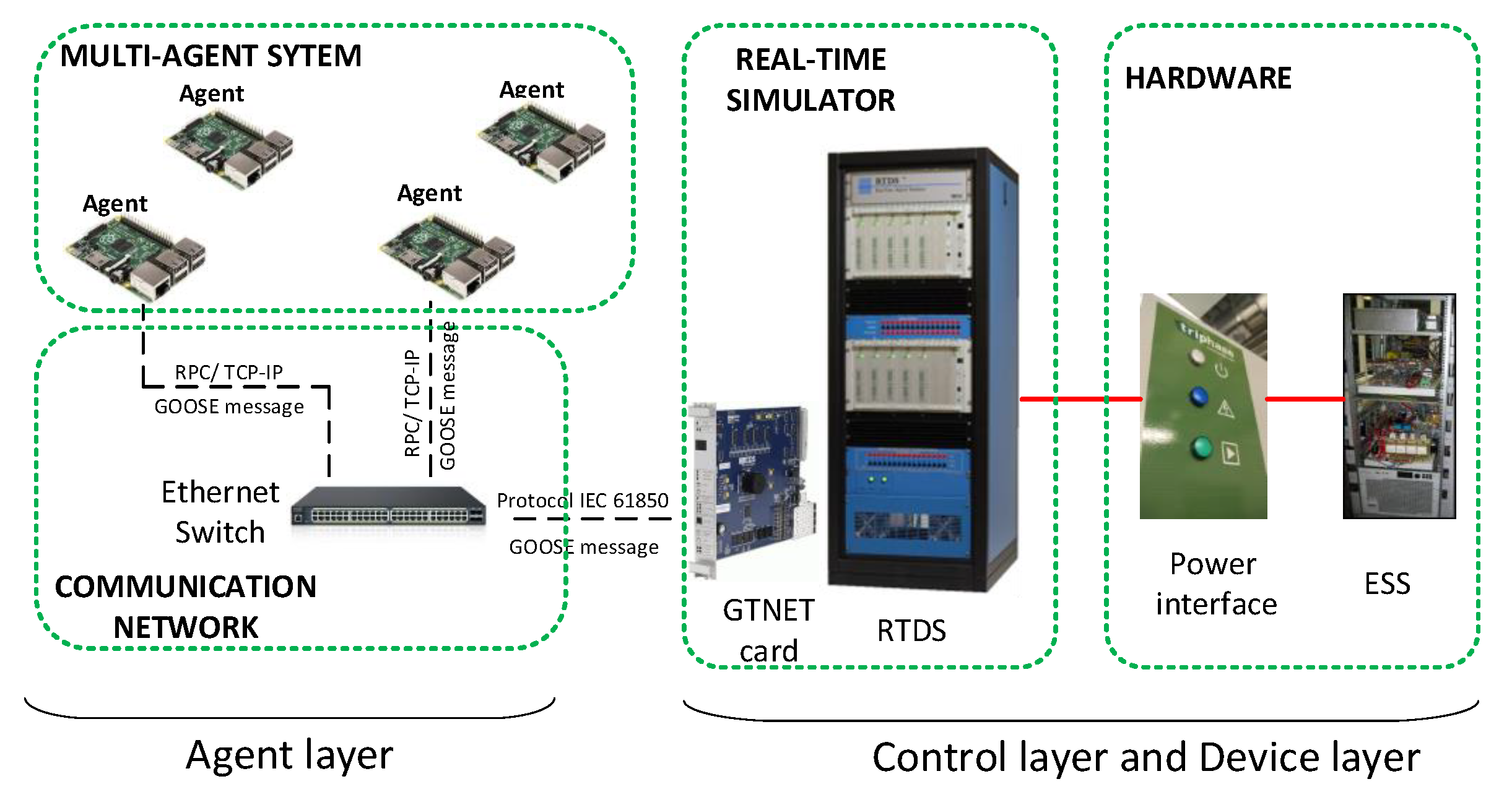
4.1. Platform Design for Validation of Distributed Control in MG

The experimental platform for this case-study (as shown in Figure 6) consists of two main groups of components: firstly a PHIL capability with a power inverter as the power component and secondly the CHIL setup with a MAS performed in a realistic communications network.

4.1.1. PHIL with Power Inverter

This part of the platform covers the Device layer and the Control layer in the layer structure. The MG (Device layer) and local controllers (Control layer) of the inverters were implemented in Real Time Digital Power System Simulator (RTDS). The testing of the distributed control can be significantly improved by adding one more layer of reality to the experiments by driving real hardware components with the controller under test. For the introduction of real dynamics into the test case, the system includes two sections: one section is composed of one ESS which is the hardware battery, emulated by the inverter, with its corresponding local controller, and one section is composed of the remaining elements of the MG simulated within the real-time simulator from RTDS Technologies.

4.1.2. CHIL with MAS and Realistic Communications Network

Agent layer in the layer structure is represented by this part of the platform. A cluster of Raspberry PIs (RPI) with custom distributed control embedded forms the multi-agent system. The RPIs connect to the laboratory communications network through an Ethernet switch. The communications among agents is in a client/server manner and can be configured to correspond under any network topology. Each agent is a server that waits for incoming messages and dispatches them to the corresponding method calls but is also a client of neighboring servers. To implement the consensus algorithm in the MAS, we use the aiomas open source framework (https://aiomas.readthedocs.io). Each agent waits for input, then compute outputs based on the input and internal states. Specifically, in our case, input of an agent is sensed from local devices and adjacent information is received from nearby agents. Agents run the average consensus process in parallel and return the convergent values to the controllers. Moreover, the inter-agent data are transmitted through physical local area network. Therefore, the convergence of distributed implementation and its impact to the power system operation is evaluated in a more realistic manner. Moreover, the disturbance of communication (i.e., latency, packet loss, cyber-attack, etc.) could be integrated directly to analyze the performance and the stability of system. Figure 7 explicitly illustrates the structure of agents that we designed. Beside of RPC server/client, asynchronous processes run in agents for implementing the algorithms as well as transferring data with outside devices.

4.1.3. Interfaces between Agents and RTDS

In the context of this paper, RPIs transfer information to RTDS through GTNETcard using IEC 61850 GOOSE (Generic Object Oriented Substation Event) protocol. IEC 61850 is an industrial protocol which improve interoperability, reduce the time required for sending real-time data and its approach is closer to industrial applications [30]. The objective is to provide utilities with a common advanced protocol for transferring information of inverter-based DERs from different vendors. The signals are distributed to make sure that RPIs can assess only local data.

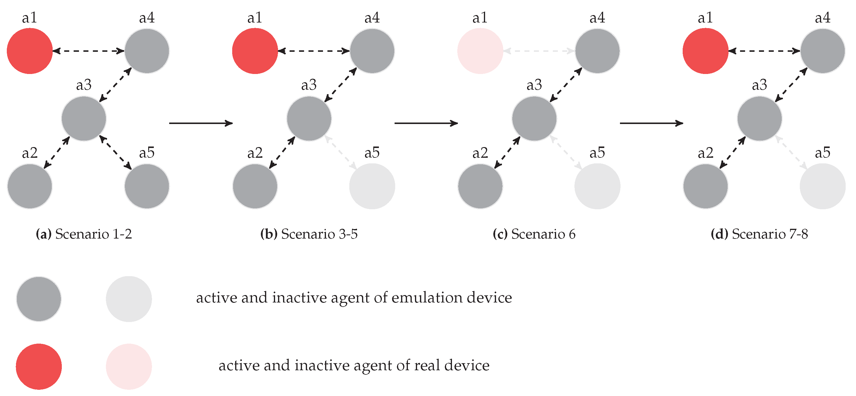
4.2. Testing Procedure

A case study of secondary control in an autonomous MG was implemented to verify the operation of the designed MAS by using the laboratory platform. The test case MG includes one load which is supplied by five ESSs. Each ESS is interfaced with the MG through a power inverter and a filter. ESS 1 is the hardware battery controlled by an emulating controller. The inverters operate in parallel, and are controlled as grid-forming converters, controlling grid frequency and voltage. The operation of an ESS and its inverter, filter as well as its local controller with agent is explicitly presented in Section 2. The parameters of inverter droop controllers were chosen to distinguish clearly the transient behavior of local frequency. The selection is also appropriate with respect to real world deployment. Many ESSs with various power capacities can be installed into the system. The rated active and droop coefficient of the controllers are presented in Table 1. The proportional gains and the integral time constants of secondary controllers of all inverters are identical.
The proposed layer structure is used to describe the test system as Figure 5. By separating the system into distinct layers, we can have a thorough overview of the system and see how data are transferred between devices, controllers and agents. For simplicity, Figure 5 only shows data flows of ESS 1 and its controller and agent. Data flows for other ESSs are identical. The controllers of inverters are decentralized as illustrated in Control layer because they only contact with local units. The system information can be obtained via agents. In the distributed manner, the information agents receive is not global but only from adjacent agents.
The performance of MAS is proven by showing that the system is stable and frequency is controlled under various changes of the MG. Eight different scenarios with alteration of network topology are emulated as illustrated in Figure 8. Initially, the MG operates in a steady state, i.e., all ESSs are connected to the system. The connection among agents is presented in Figure 8a. In Scenarios 1 and 2, we increase and decrease load power respectively. In Scenario 3, ESS 5 is disconnected leading to the removal of Agent 5 out of the MAS as in Figure 8b. Then, the load is changed in Scenarios 4 and 5 to verify the operation of the agent system after removing one unit. In Scenario 6, we trip ESS 1 to test the adaption ability of MAS with hardware device. In this scenario, the MAS operates with only three agents, as shown in Figure 8c. Finally, in Scenario 7, ESS 1 is reconnected to the system and in Scenario 8, the load is changed again to justify the operation of MAS upon addition of an agent. The experiment procedure was carried out continuously and throughout from Scenario 1 to Scenario 8 to prove ability of on-line self configuration of agents. A scenario commences when the previous scenario is completed and the system has reached steady state (i.e., frequency has returned to its nominal value).

4.3. Experimental Results

Efficiency of the proposed distributed control is verified by observing the following: (1) iterative state values in each agent to show convergence performance of consensus process; (2) values of signals controllers receives from agents; (3) local frequency measurements; (4) ESS active power outputs; and (5) consensus computation performance.

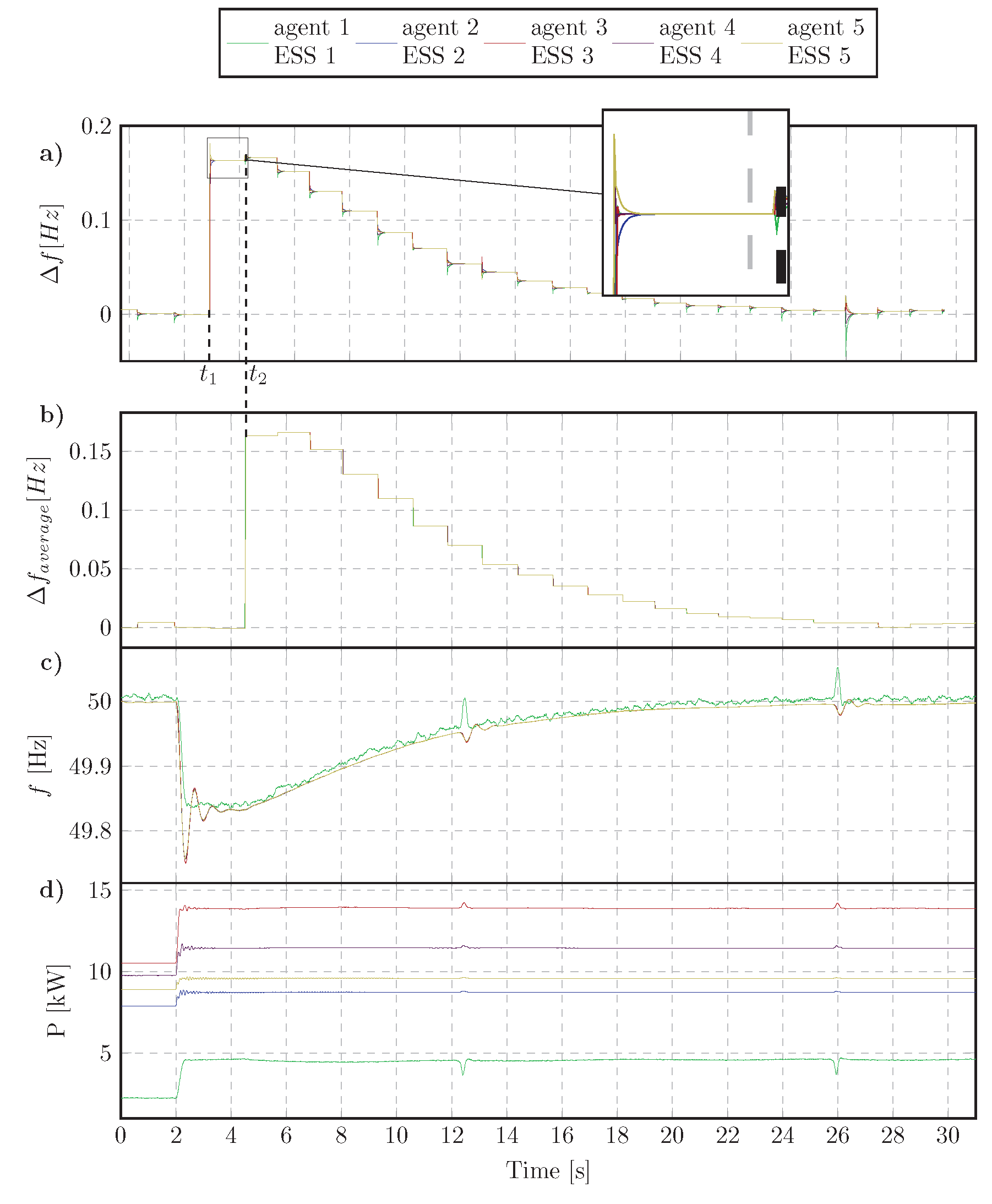
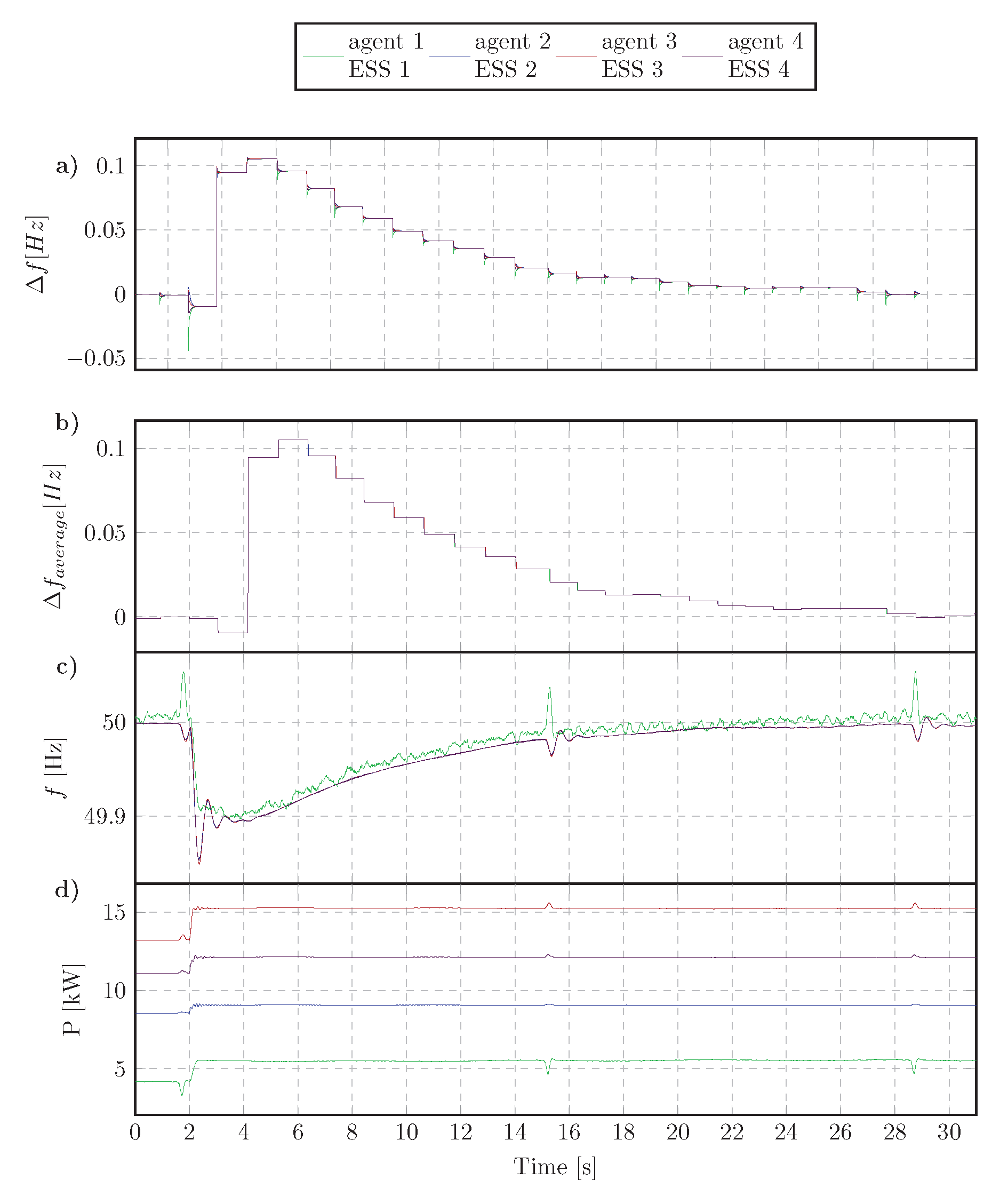
4.3.1. Step Change of Load Active Power

In the first two scenarios, when the MG consists of five ESSs, changes in active power of the load are simulated to examine the operation of system under fixed (normal) condition of network topology. Firstly, in Scenario 1, the load power was increased from 27 kW to 36 kW. Then, Scenario 2 was implemented by reducing the load power to 25 kW. The results of the two scenarios are presented in Figure 9 and Figure 10 respectively.
As in Figure 9d and Figure 10d, at the time the load was altered, power outputs of all ESSs are changed accordingly to compensate the unbalanced power following the droop rule to stabilize system. Specifically, during about first 2 s, where the inverters were under only primary control, a steady-state frequency deviation from the nominal value exists as observed in Figure 9c and Figure 10c.
To express thoroughly the computation of a consensus loop process in agents, we consider a duration from t 1 to t 2 as illustrated in Figure 9a and Figure 10a. Agents process the calculation as presented in Algorithm 1. At t 1 , corresponding to Step 1 in the algorithm, all agents receive new initial states and the local frequency deviations. The agents then exchange information, conduct the calculation, and obtain the convergence at t 2 , corresponding to Step 17 in the algorithm. The considered process was finished when the results (state values at t 2 ) were sent to the controllers. The new consensus loop was begun upon receiving new initial state by means of updating the measurements.
The statistics of the calculation time for a consensus process are shown in Figure 11. The time is collected based on logging operation of agents. The values is not immutable but fluctuates in the range mainly from 1.17 s to 1.26 s. This is because the agents communicate in a real physical network environment in the laboratory. Even though the delay for transporting data may be nonsensical due to short distances between agents (raspberry PIs in the designed platform), the performance of transferring data has closely approached to practical network implementation.
It can be observed that, although communications delays are uncertain, consensus time is still nearly analogous in all agents. Moreover, five traces of controller inputs (Figure 9b and Figure 10b) overlap demonstrating synchronous operation of MAS to send the average values of frequency errors to secondary controllers concurrently. The MAS takes the role similar to a central controller in the centralized control regime to send global information to local controllers. The controller of an ESS inverter is a closed loop control system with feedback signal is the frequency error. Instead of receiving continuously from the central controller, the PI controller in secondary control level of this system updates the feedback from the agent. However, as above analysis, the agent need time for completing a consensus loop process and reach the final state. The sample rate of feedback signal depends on the calculation time in agent and the time for sending data. The network quality and computation performance of agents therefore can significantly affect to the control system which in turn may cause instabilities in the grid. Hence, the selection of parameters of PI controllers plays an important role in controlling the system. Frequency of the grid system under proposed distributed control was restored accurately to its nominal value within approximately 30 s of the occurrence of the disturbance.

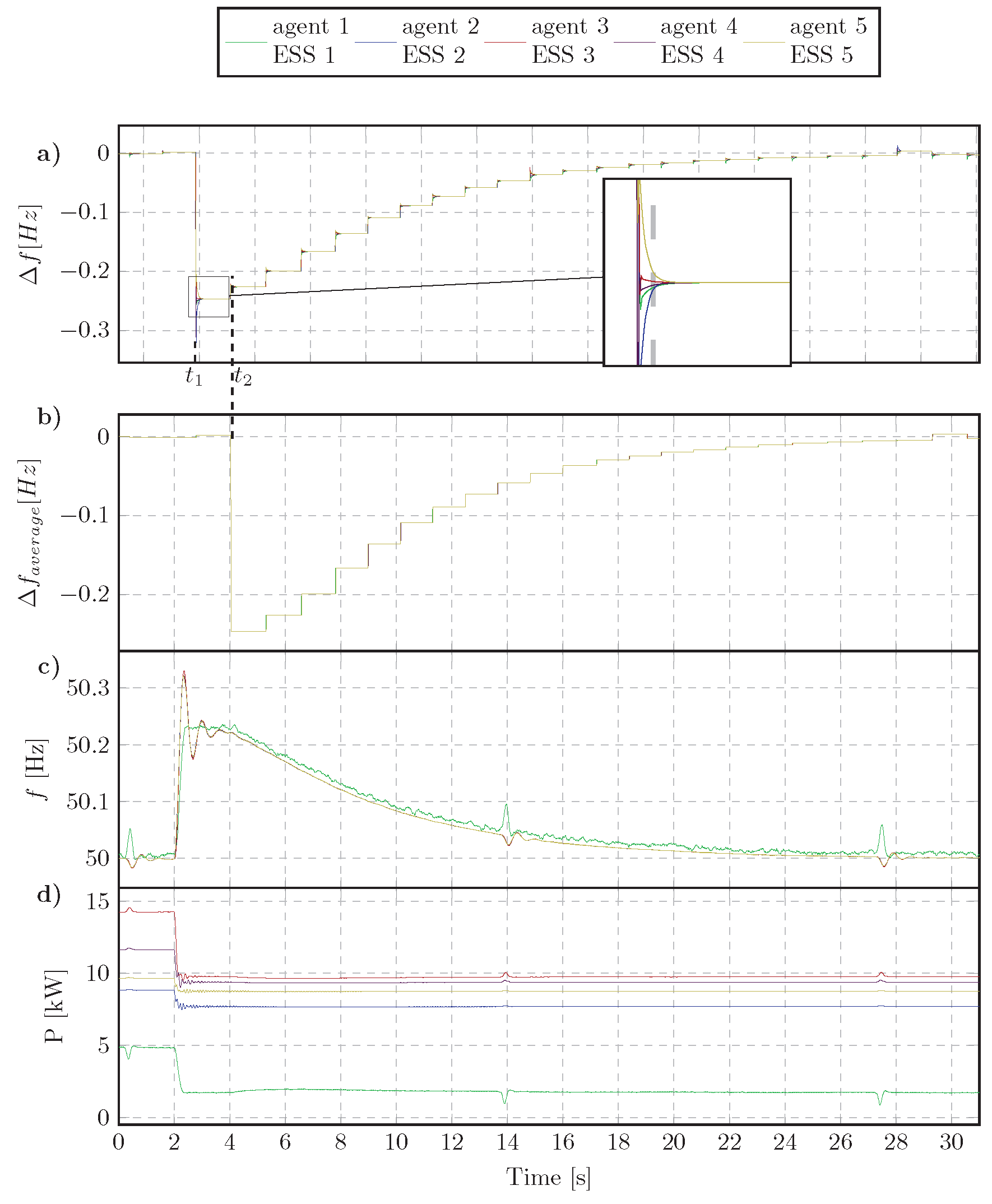
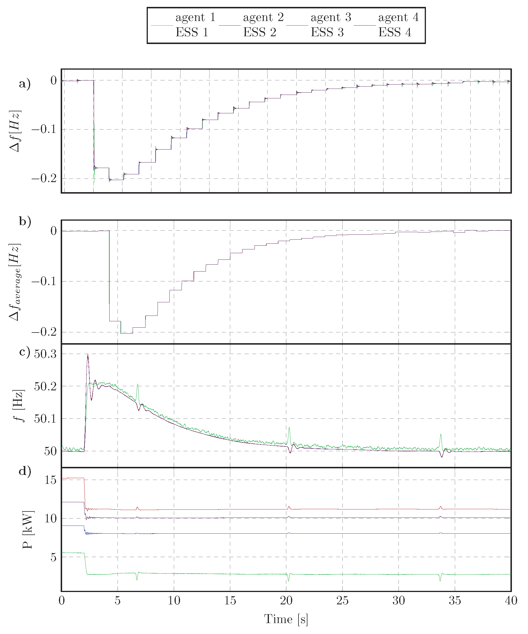
4.3.2. Disconnecting an ESS

In Scenario 3, ESS 5 is tripped and in turn Agent 5 will be out of service. At this time, the topology of MAS network was transformed by excluding one node and one connection line as in Figure 8b. Agent 3 loses a neighbor, thus values of elements of weight matrix are no longer correct. The modification for Agent 3 is mandatory for proper consensus process in MAS. The reconfiguration process in Agent 3 is triggered when receiving inform message from Agent 5 as described in Section 3. Figure 12 presents the results of system in Scenario 3. When ESS 5 is disconnected, the remaining ESSs have to increase of power output to share the power previously supplied by ESS 5. The frequency is reduced as the result of droop controllers. Figure 12a shows the convergence of consensus processes in agents which proves the capability of on-line adaptability of Agent 3 when its neighbor—Agent 5—is removed. The frequency of system is controlled to return to reference value after the trip event occurs.
To inevitably verify the operation of agents against disturbances, two different events of changing load power were conducted in two successive scenarios. In Scenario 4, the load power is increased to 30 kW and, in Scenario 5, it is reduced to 20 kW. The results are presented respectively in Figure 13 and Figure 14 to ascertain the agent-based distributed algorithm. Similar to the results collected in previous scenarios, the system frequency is gradually restored and kept steady at 50 Hz as initial state. The time for a consensus loop process of the MAS with 4 agents depicted in Figure 15. Each process needs approximately 1.1 s to be accomplished. Compared with the first scenarios, it is slightly faster due to the reduction of MAS complexity and the decreasing quantity of agents.
Scenario 6 was implemented to check the resilience of system when the physical hardware ESS was disconnected from the grid. Agent 1 was shut down along with ESS 1 and eliminated from neighbor list of Agent 4. Agent 4, as aforementioned, also reconfigured itself to adapt to the new condition. The topology of MAS is switched as Figure 8c with only three agents and two communication lines. To ensure firmly the safety of devices, the real ESS was not tripped out abruptly. Alternatively, we declined gradually the load power to zero. Therefore, as can be seen from the results depicted in Figure 16, the remaining ESSs did not change immediately but increased slowly and reached to stable values after about 20 s. Although there are significant differences in implementation, the system was still robust to disturbances under distributed control with the MAS. The convergence of computation in agents was assured to send precise signals to secondary controllers. Figure 17 shows the performance of consensus processes in the agents. Agents computed faster (mainly about 0.86 s) yet ensured to reach the consensus state. The system with consistently chosen PI parameters was proved to be stable under various changes of feedback signals.

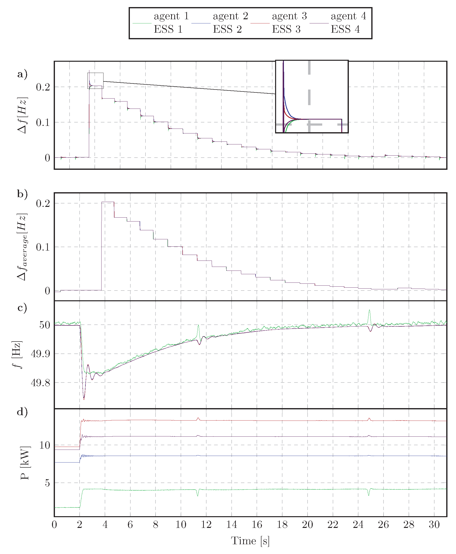
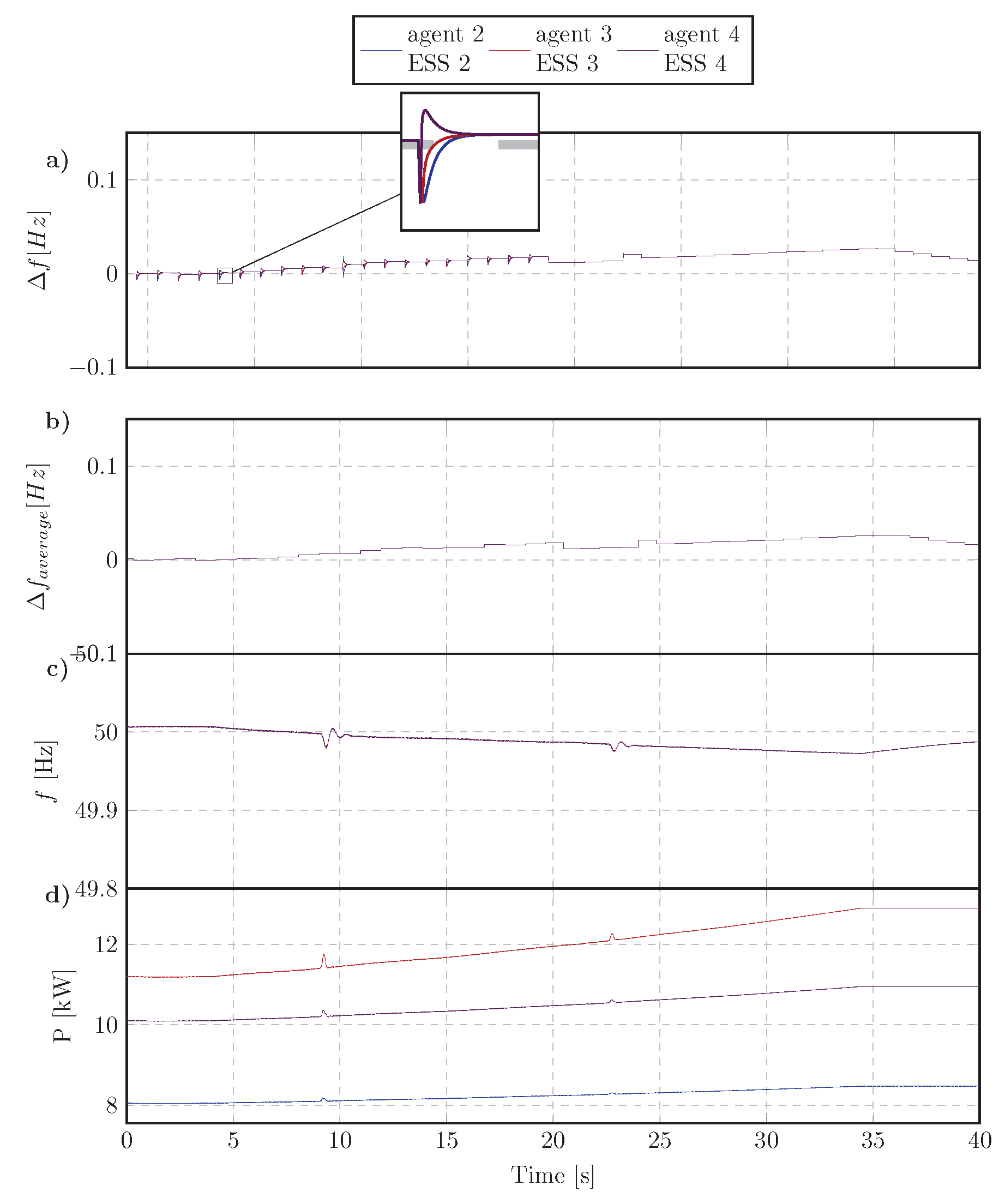
4.3.3. Connecting an ESS to MG

In Scenario 7, we check the implementation of the MAS as well as the operation of the test case when one more agent is added. In this case, we reconnected the hardware ESS which was tripped out in previous scenarios and the system comes back to the state as in Scenarios 3–5. Agent 1 was activated again and the connection link between Agent 1 and Agent 4 was also established as Figure 8d. As described in Section 3, the agents in this case have to handle more complex tasks to embed a new agent into an operating MAS. Agent 1 was started together with ESS 1 and it instantly informed its appearance in the network to neighbor (Agent 4). It is noted that in order to avoid a high transient current and cause adverse effects to devices when connecting ESS 1 to the grid, instead of closing a breaker, we adjusted the reference power P 0 in controller of Inverter 1 to increase gradually the power output of ESS 1 to desired value. The results of this scenario are shown in Figure 18.
Figure 18a illustrates the convergence of state values in MAS after adding new agent. Before proceeding the consensus computation, at initial phase, Agent 1 waited for feedback from neighbors (Agent 4) to seek current iteration of MAS. Agent 4 also included Agent 1 to be one of its neighbors. Although the secondary process for regularizing frequency was prolonged due to the connection procedure of physical ESS, the results expressed that the system was still under robust control to be stabilized in the nominal state. An power increase of load was then conducted to prove the proper operation of the system in the new state as shown in Figure 19.

5. Conclusions

This paper proposed a multi-agent system with plug and play feature for operation in distributed secondary frequency control of islanded MG. The agents are designed to interface devices from different vendors via the industrial protocol IEC 61850. The agents implement an average consensus algorithm by using local measurements and interacting with neighbors to return the identical average signals of frequency deviations to local controllers. The proposed approach is resilient to various disturbances in MG and provides plug and play feature that enable online re-configuration of the network in the case of alteration of topology, hence, interoperability at agent layer. A test case autonomous MG with various scenarios was conducted to validate the operating of the proposed agent under PHIL setup, hardware agent system and realistic communication network. The results have shown that under alterations of network topology, the recovery of grid frequency was always ensured with the MAS control. Communications between agents and consensus time were also investigated with real implementation.
In the future work, the ability to work with large scale system will be investigated and the experimental platform will be improved to deal with more cyber-security issues.

Author Contributions

T.-L.N. conceived the research idea with suggestions from C.G. and N.-A.L.; T.-L.N., E.G.-S., M.H.S. performed the experiments and analyzed the data; S.M.B. and L.R. contributed to the HIL setup; T.-L.N., E.G.-S., M.H.S. and V.-H.N. wrote the paper; and Q.-T.T., R.C and G.M.B. oversaw the work and proofread the paper.

Funding

This work was partly supported by: (1) the European Community’s Horizon 2020 Program (H2020/2014–2020) under the project “ERIGrid: European Research Infrastructure supporting Smart Grid Systems Technology Development, Validation, and Roll Out” (Grant No. 654113); and (2) the European Union Seventh Framework Programme (FP7) under the project ELECTRA IRP (Grant No. 609687).

Conflicts of Interest

The authors declare no conflict of interest.

References

  1. Hatziargyriou, N. Microgrids: Architectures and Control; John Wiley & Sons: Hoboken, NJ, USA, 2014; pp. 1–344. [Google Scholar] [CrossRef]
  2. Yazdanian, M.; Mehrizi-Sani, A. Distributed control techniques in microgrids. IEEE Trans. Smart Grid 2014, 5, 2901–2909. [Google Scholar] [CrossRef]
  3. Olivares, D.E.; Mehrizi-Sani, A.; Etemadi, A.H.; Cañizares, C.A.; Iravani, R.; Kazerani, M.; Hajimiragha, A.H.; Gomis-Bellmunt, O.; Saeedifard, M.; Palma-Behnke, R.; et al. Trends in microgrid control. IEEE Trans. Smart Grid 2014, 5, 1905–1919. [Google Scholar] [CrossRef]
  4. Guerrero, J.M.; Chandorkar, M.; Lee, T.; Loh, P.C. Advanced Control Architectures for Intelligent Microgrids; Part I: Decentralized and Hierarchical Control. IEEE Trans. Ind. Electron. 2013, 60, 1254–1262. [Google Scholar] [CrossRef]
  5. Gomez-Sanz, J.J.; Garcia-Rodriguez, S.; Cuartero-Soler, N.; Hernandez-Callejo, L. Reviewing microgrids from a multi-agent systems perspective. Energies 2014, 7, 3355–3382. [Google Scholar] [CrossRef]
  6. Colson, C.M.; Nehrir, M.H. Comprehensive real-time microgrid power management and control with distributed agents. IEEE Trans. Smart Grid 2013, 4, 617–627. [Google Scholar] [CrossRef]
  7. Kantamneni, A.; Brown, L.E.; Parker, G.; Weaver, W.W. Survey of multi-agent systems for microgrid control. Eng. Appl. Artif. Intell. 2015. [Google Scholar] [CrossRef]
  8. Dragicevic, T.; Wu, D.; Shafiee, Q.; Meng, L. Distributed and Decentralized Control Architectures for Converter-Interfaced Microgrids. Chin. J. Electr. Eng. 2017, 3, 41–52. [Google Scholar]
  9. Shafiee, Q.; Stefanovic, C.; Dragicevic, T.; Popovski, P.; Vasquez, J.C.; Guerrero, J.M. Robust Networked Control Scheme for Distributed Secondary Control of Islanded Microgrids. IEEE Trans. Ind. Electron. 2014, 61, 5363–5374. [Google Scholar] [CrossRef] [Green Version]
  10. Dehkordi, N.M.; Sadati, N.; Hamzeh, M. Fully Distributed Cooperative Secondary Frequency and Voltage Control of Islanded Microgrids. IEEE Trans. Energy Convers. 2017, 32, 675–685. [Google Scholar] [CrossRef]
  11. Zhang, G.; Li, C.; Qi, D.; Xin, H. Distributed Estimation and Secondary Control of Autonomous Microgrid. IEEE Trans. Power Syst. 2017, 32, 989–998. [Google Scholar] [CrossRef]
  12. Dehkordi, N.M.; Sadati, N.; Hamzeh, M. Distributed Robust Finite-Time Secondary Voltage and Frequency Control of Islanded Microgrids. IEEE Trans. Power Syst. 2017, 32, 3648–3659. [Google Scholar] [CrossRef]
  13. Raju, L.; Milton, R.S.; Mahadevan, S. Multi agent systems based distributed control and automation of micro-grid using MACSimJX. In Proceedings of the 2016 10th International Conference on Intelligent Systems and Control (ISCO), Coimbatore, India, 7–8 January 2016; pp. 1–6. [Google Scholar] [CrossRef]
  14. Harmouch, F.Z.; Krami, N.; Benhaddou, D.; Hmina, N.; Zayer, E.; Margoum, E.H. Survey of multiagents systems application in Microgrids. In Proceedings of the 2016 International Conference on Electrical and Information Technologies (ICEIT), Tangiers, Morocco, 4–7 May 2016; pp. 270–275. [Google Scholar] [CrossRef]
  15. Nelson, A.; Chakraborty, S.; Wang, D.; Singh, P.; Cui, Q.; Yang, L.; Suryanarayanan, S. Cyber-physical test platform for microgrids: Combining hardware, hardware-in-the-loop, and network-simulator-in-the-loop. In Proceedings of the IEEE Power and Energy Society General Meeting, Boston, MA, USA, 17–21 July 2016. [Google Scholar] [CrossRef]
  16. Kotsampopoulos, P.C.; Lehfuss, F.; Lauss, G.F.; Bletterie, B.; Hatziargyriou, N.D. The limitations of digital simulation and the advantages of PHIL testing in studying distributed generation provision of ancillary services. IEEE Trans. Ind. Electron. 2015. [Google Scholar] [CrossRef]
  17. Guillo-Sansano, E.; Syed, M.H.; Roscoe, A.J.; Burt, G.M. Initialization and Synchronization of Power Hardware-In-The-Loop Simulations: A Great Britain Network Case Study. Energies 2018, 11. [Google Scholar] [CrossRef]
  18. Nguyen, T.; Guillo-Sansano, E.; Syed, M.H.; Blair, S.M.; Reguera, L.; Tran, Q.; Caire, R.; Burt, G.M.; Gavriluta, C.; Nguyen, V. Systems Level Validation of a Distributed Frequency Control Algorithm. In Proceedings of the 2018 IEEE International Conference on Environment and Electrical Engineering and 2018 IEEE Industrial and Commercial Power Systems Europe (EEEIC/I CPS Europe), Palermo, Italy, 12–15 June 2018; pp. 1–6. [Google Scholar] [CrossRef]
  19. Shafiee, Q.; Guerrero, J.M.; Vasquez, J.C. Distributed secondary control for islanded microgrids-a novel approach. IEEE Trans. Power Electron. 2014. [Google Scholar] [CrossRef]
  20. Chen, M.; Syed, M.H.; Sansano, E.G.; McArthur, S.D.; Burt, G.M.; Kockar, I. Distributed negotiation in future power networks: Rapid prototyping using multi-agent system. In Proceedings of the IEEE PES Innovative Smart Grid Technologies Conference Europe, Ljubljana, Slovenia, 9–12 October 2017. [Google Scholar] [CrossRef]
  21. Guo, J.; Hug, G.; Tonguz, O.K. On the Role of Communications Plane in Distributed Optimization of Power Systems. IEEE Trans. Ind. Inform. 2017. [Google Scholar] [CrossRef]
  22. Nguyen, V.H.; Tran, Q.T.; Besanger, Y. SCADA as a service approach for interoperability of micro-grid platforms. Sustain. Energy Grids Netw. 2016, 8, 26–36. [Google Scholar] [CrossRef]
  23. Nguyen, V.H.; Besanger, Y.; Tran, Q.T.; Nguyen, T.L. On Conceptual Structuration and Coupling Methods of Co-Simulation Frameworks in Cyber-Physical Energy System Validation. Energies 2017, 10, 1977. [Google Scholar] [CrossRef]
  24. Tolk, A.; Muguira, J. The levels of conceptual interoperability model. In Proceedings of the 2003 Fall Simulation Interoperability Workshop, Orlando, FL, USA, 14–19 September 2003. [Google Scholar]
  25. Lu, X.; Yu, X.; Lai, J.; Wang, Y.; Guerrero, J.M. A Novel Distributed Secondary Coordination Control Approach for Islanded Microgrids. IEEE Trans. Smart Grid 2017. [Google Scholar] [CrossRef]
  26. Han, Y.; Li, H.; Shen, P.; Coelho, E.; Guerrero, J. Review of Active and Reactive Power Sharing Strategies in Hierarchical Controlled Microgrids. IEEE Trans. Power Electron. 2016, 8993. [Google Scholar] [CrossRef]
  27. Bidram, A.; Davoudi, A. Hierarchical structure of microgrids control system. IEEE Trans. Smart Grid 2012, 3, 1963–1976. [Google Scholar] [CrossRef]
  28. Guerrero, J.M.; Vasquez, J.C.; Matas, J.; de Vicuna, L.G.; Castilla, M. Hierarchical Control of Droop-Controlled AC and DC Microgrids—A General Approach Toward Standardization. IEEE Trans. Ind. Electron. 2011, 58, 158–172. [Google Scholar] [CrossRef]
  29. Sayed, A.H. Adaptive Networks. Proc. IEEE 2014, 102, 460–497. [Google Scholar] [CrossRef]
  30. Blair, S.M.; Coffele, F.; Booth, C.D.; Burt, G.M. An Open Platform for Rapid-Prototyping Protection and Control Schemes With IEC 61850. IEEE Trans. Power Deliv. 2013, 28, 1103–1110. [Google Scholar] [CrossRef] [Green Version]
Figure 1. Layer structure.
Energies 11 03253 g001
Figure 2. An inverter based interface ESS in the layer structure.
Energies 11 03253 g002
Figure 3. Algorithm of agent system when an ESS is out of MG.
Energies 11 03253 g003
Figure 4. Algorithm of agent system when an ESS is added to MG.
Energies 11 03253 g004
Figure 5. The MG case study in the layer structure.
Energies 11 03253 g005
Figure 6. The designed laboratory platform.
Energies 11 03253 g006
Figure 7. Structure of agents.
Energies 11 03253 g007
Figure 8. Topology of MAS in ech scenario.
Energies 11 03253 g008
Figure 9. Scenario 1. (a) The state values of agents; (b) Consensus values sent to controllers from agents; (c) Frequency values measured at output of ESSs; and (d) Active power output of ESSs.
Energies 11 03253 g009
Figure 10. Scenario 2. (a) The state values of agents; (b) Consensus values sent to controllers from agents; (c) Frequency values measured at output of ESSs; and (d) Active power output of ESSs.
Energies 11 03253 g010
Figure 11. Time of one loop consensus process Scenarios 1–2.
Energies 11 03253 g011
Figure 12. Scenario 3. (a) The state values of agents; (b) Consensus values sent to controllers from agents; (c) Frequency values measured at output of ESSs; and (d) Active power output of ESSs.
Energies 11 03253 g012
Figure 13. Scenario 4. (a) The state values of agents; (b) Consensus values sent to controllers from agents; (c) Frequency values measured at output of ESSs; and (d) Active power output of ESSs.
Energies 11 03253 g013
Figure 14. Scenario 5. (a) The state values of agents; (b) Consensus values sent to controllers from agents; (c) Frequency values measured at output of ESSs; and (d) Active power output of ESSs.
Energies 11 03253 g014
Figure 15. Time of one loop consensus process Scenarios 3-5.
Energies 11 03253 g015
Figure 16. Scenario 6. (a) The state values of agents; (b) Consensus values sent to controllers from agents; (c) Frequency values measured at output of ESSs; and (d) Active power output of ESSs.
Energies 11 03253 g016
Figure 17. Time of one loop consensus process Scenario 6.
Energies 11 03253 g017
Figure 18. Scenario 7. (a) The state values of agents; (b) Consensus values sent to controllers from agents; (c) Frequency values measured at output of ESSs; and (d) Active power output of ESSs.
Energies 11 03253 g018
Figure 19. Scenario 8. (a) The state values of agents; (b) Consensus values sent to controllers from agents; (c) Frequency values measured at output of ESSs; and (d) Active power output of ESSs.
Energies 11 03253 g019
Table 1. Parameters of ESS inverter controllers.
ParameterValueUnit
Inverter 1 P 0 1 3kW
k P 1 100Hz/kW
Inverter 2 P 0 2 8kW
k P 2 200Hz/kW
Inverter 3 P 0 3 11kW
k P 3 50Hz/kW
Inverter 4 P 0 4 10kW
k P 4 100Hz/kW
Inverter 5 P 0 5 9kW
k P 5 250Hz/kW
Secondary controllers K p 0.01
K i 0.12

