Modelling and Designing Cryogenic Hydrogen Tanks for Future Aircraft Applications
by
 , and
, and
Christopher Winnefeld
1, 
Thomas Kadyk
2,
Boris Bensmann
1,*,
Ulrike Krewer
2 and
Richard Hanke-Rauschenbach
1 1
Institute of Electric Power Systems, Leibniz Universität Hannover, Appelstr. 9a, 30167 Hanover, Germany
2
Institute of Energy and Process Systems Engineering, TU Braunschweig, Franz-Liszt-Straße 35, 38106 Braunschweig, Germany
*
Author to whom correspondence should be addressed.
Energies 2018, 11(1), 105; https://doi.org/10.3390/en11010105
Submission received: 14 December 2017
/
Revised: 16 December 2017
/
Accepted: 26 December 2017
/
Published: 3 January 2018
(This article belongs to the Special Issue Towards a Transformation to Sustainable Aviation Systems)
Abstract
:In the near future, the challenges to reduce the economic and social dependency on fossil fuels must be faced increasingly. A sustainable and efficient energy supply based on renewable energies enables large-scale applications of electro-fuels for, e.g., the transport sector. The high gravimetric energy density makes liquefied hydrogen a reasonable candidate for energy storage in a light-weight application, such as aviation. Current aircraft structures are designed to accommodate jet fuel and gas turbines allowing a limited retrofitting only. New designs, such as the blended-wing-body, enable a more flexible integration of new storage technologies and energy converters, e.g., cryogenic hydrogen tanks and fuel cells. Against this background, a tank-design model is formulated, which considers geometrical, mechanical and thermal aspects, as well as specific mission profiles while considering a power supply by a fuel cell. This design approach enables the determination of required tank mass and storage density, respectively. A new evaluation value is defined including the vented hydrogen mass throughout the flight enabling more transparent insights on mass shares. Subsequently, a systematic approach in tank partitioning leads to associated compromises regarding the tank weight. The analysis shows that cryogenic hydrogen tanks are highly competitive with kerosene tanks in terms of overall mass, which is further improved by the use of a fuel cell.
1. Introduction
In future aircraft scenarios, facing challenges to satisfy the global market growth requires new approaches in air transport solutions while simultaneously reducing the environmental impact. Boeing [1] and Airbus [2] predict revenue passenger kilometres to double in less than 20 years. In addition, twice the current fleet is expected to operate until 2036 as well. In order to achieve sufficient reduction of overall aviation-related emissions, new propulsion technologies and aircraft designs along with tremendous aerodynamic improvements have to be introduced. In the visionary commitment Flightpath 2050 [3], emissions should be cut by 75%, emissions by 90% and noise footprint by 60% in 2050 compared to the reference value of the year 2000. Considering a supply by fossil fuel, these goals appear to be far from being achieved.
In order to replace fossil fuels, hydrogen is a reasonable candidate for a prospective energy supply with a gravimetric energy density of 33.3 kWh/kg compared to kerosene with 12 kWh/kg. Assuming its production by renewable energy sources, the well-to-wheel emissions in terms of greenhouse gases can be reduced significantly. Although hydrogen can be stored in several ways, only liquid hydrogen () appears to be feasible in aviation. Gaseous hydrogen () offers a specific volume of 5.6-times the volume of , if stored at 164 bar and 288.15 K [4]. Additionally, the tank-wall thicknesses rise tremendously for the required internal pressures, which are at least two orders of magnitude greater than the cryogenic storage solution [5]. Reasonable numbers in the share of hydrogen mass on composite tank mass are between 7.5% and 8.5%, while steel cylinders provide values between 1% and 3% [6]. Gaseous hydrogen can further be stored in metal hydrides. However, this technology offers a capability of about 5% mass fraction of hydrogen [5,7]. Although metal borohydrides store hydrogen mass fractions greater than 10% in more recent studies about unmanned aerial vehicles, those storage densities with associated challenges regarding the rate of fuel withdrawal do not appear to represent the favoured storage option [6].
Numerous studies, such as from Lockheed and NASA [8] or the Cryoplane project [9], attest to the feasibility of liquid hydrogen as aviation fuel. Brewer [7] summarised various studies on hydrogen-fuelled passenger aircraft showing slightly higher (1–2%) operating empty weights. Gross weights can be reduced by 20% for medium range and by 10% for short range aircraft. Furthermore, the fuel shares approximately 72% in the fuel system weight. The results by Verstraete [10] demonstrate similar behaviour in terms of energy density of the storage system. Values of approximately 78% are reached relating the hydrogen mass on the sum of system and fuel mass. Common practical kerosene tanks offer fuel shares of around 75% including periphery [11]. These theoretical studies show that the cryogenic hydrogen tank has a significant share of the fuel, but are nonetheless competitive with kerosene tanks. Consequently, the storage density is mainly driven by the tank design. For this reason, it is worth investigating the hydrogen tank more in detail. Since the direct operating costs (DOCs) and aerodynamic requirements of an aircraft relate directly to the mass, the herein presented study evaluates mainly weight-dependent parameters. In addition to that, the energy density of the hydrogen storage shall be investigated and compared preferable to conventional jet fuel. For these reasons, a mass-related evaluation appears to be suitable and is further applied to this study.
Whereas previous studies on cryogenic hydrogen tanks discuss the storage dimensioning only on particular aircraft geometries, this contribution covers a general approach. Future aircraft concepts provide more volume especially in the outer and rear fuselage parts compared to conventional aircraft designs. A more effective use of cylindrical and elliptical tank designs appears to be enabled [12]. Furthermore, complex tank geometries, such as obround and complex conformal tanks, are feasible [13]. Motivated by those aircraft concepts, a widely-flexible description of cylindrical and elliptical tank shapes is applied. Along with future energy storage concepts, a fuel cell is considered to supply the propulsion system with electrical power. Because of its superior efficiency compared to conventional aero engines, the feasibility of hydrogen storage increases, because of less fuel burn [11].
Dimensionless parameters are introduced characterising the tank geometry and enabling a flexible geometric description. An objective of this study is to elaborate the most favourable design if a spherical geometry is unpractical or rather a non-cylindrical design is contemplated. Further evaluations show expected shares of the tank wall and insulation mass in the overall tank mass while making the evaluation process more transparent. Within the first phase of this study, the hydrogen tank is observed only. Commencing with an overview about hydrogen properties, a description of the tank-design approach follows subsequently. Parametric studies are executed based on a specific flight mission after introducing the tank model. Conclusively, a comparison in terms of weight is drawn between hydrogen and kerosene tanks.
2. Principles of the Modelling Approach
This chapter introduces the principles of the modelling approach. Since the focus of the present contribution is on cryogenic hydrogen storage, the first section provides brief information about thermodynamic properties of hydrogen in general. The subsequent section treats the modelling approach of the tank design followed by paragraphs about the operation management and the overall design routine.
2.1. Properties of
To classify the characteristics of hydrogen, selected thermodynamic properties are compared to conventional jet fuel. In the following, additional peculiarities of hydrogen are discussed. The main advantage of hydrogen compared to conventional Jet-A fuel is the 2.8-times greater heat of combustion. Attributed to its superior heat capacity, hydrogen appears to be more suitable for component cooling especially if electrically-driven propulsion systems and superconductors are considered. Nevertheless, liquid hydrogen stored at 1 bar requires four-times the volume of jet fuel for the same energy amount. It further ought to be stored at cryogenic temperatures. Table 1 summarises selected properties of liquid hydrogen and jet fuel.
If normal hydrogen is liquefied, ortho- converts spontaneously into para- under exothermic conditions. For long-term storages, this leads to considerable boil-off rates depending on the ambient temperature. Triggering this conversion during the liquefaction process, which requires a certain amount of extra energy input, avoids the hydrogen conversion afterwards. Depending on the application, considering this conversion during liquefaction is favourable from the economic perspective. In accordance with Verstraete [10], para-hydrogen is used to enable a more conservative tank design, because the pressure fluctuations are slightly greater (ca. 1%). Since the basic characteristics of para-hydrogen are similar to normal-hydrogen, in the following, the term “hydrogen” is introduced, although the properties of para-hydrogen are taken as a basis.
To reduce the disadvantage in the density of hydrogen gas, hydrogen is considered in saturation state under associated cryogenic temperatures. As a consequence, the liquid and gaseous phase are in thermodynamic equilibrium. The fluid pressure corresponds to the saturation pressure, which is only a function of temperature (see Figure 1a). The thermodynamic properties, such as densities and internal energies of both phases, are provided by the equation of state by Leachman et al. [16]. Since the density characteristics are of exceptional importance to the tank volume, Figure 1b shows the density of liquid () and gaseous () hydrogen in the saturation state.
Saturated hydrogen with the temperature as shown in Figure 1a poses technical challenges to the design process. Another characteristic shows that the density of saturated liquid hydrogen drops absolutely more strongly than the density of the gaseous phase, which is further contextualised in Section 2.2.1. Assuming a constant density for a particular pressure, a certain vapour mass fraction x is determined according to the thermodynamic equilibrium. If the pressure increases, condensates leading to a new equilibrium and a decrease in vapour mass fraction. Otherwise, a pressure drop yields boiling off the liquid until the equilibrium state is reached.
2.2. Cryogenic Tank Design
Having introduced the fluid, which shall be stored, this section discusses the required modules and constraints of the tank design approach. The first paragraphs contain the tank model, which in turn covers the geometric, mechanical and thermal design modules, fundamental assumptions, as well as boundary conditions, such as material properties. Subsequently, the overall design process is shown schematically.
2.2.1. Determining the Tank Volume
Before the tank volume is determined, a discussion of additional parameters is given. Resulting from a certain heat input, e.g., during the flight or holding-phases on the ground, the pressure rises according to the boil-off rate inside the tank. Once the pressure reaches the maximum allowable tank pressure, venting might be necessary to keep or decrease the pressure level. Therefore, the venting pressure is denoted as the maximum allowable pressure. Assuming liquid hydrogen is vented, a higher venting mass is needed to achieve sufficient pressure drop rates. From this perspective, a certain gaseous volume fraction should be available in the case of venting, which is set to 3%. Correspondingly, the maximum liquid volume fraction is [10]. The venting pressure itself ought to be selected to determine the fluid density and therefore the required tank volume for a certain amount of fuel. It has to be considered that increasing the fluid pressure yields a drop of the saturated density, whereas the density of the gaseous phase behaves in a contrary manner. In Figure 2a, the density of the homogeneous mixture () is plotted against pressure.
The tank volume must be increased by 5% for a venting pressure of 2 bar compared to 1 bar (see Figure 2a). A further increase in venting pressure to 4 bar results in a density drop of 11%. Another relevant parameter applies to the filling conditions of the tank. To ensure suitable venting of , the tank must be filled initially with a gaseous volume fraction depending on the filling pressure and venting pressure. According to Figure 2b, the fraction of liquid hydrogen available is reduced by increasing venting and deceasing filling pressure considerably. Assuming bar, the tank can be filled with for and with 86% for a venting pressure of 4 bar. As a consequence, less mass is available, which can be withdrawn. To sum up, the internal volume of the tank can be determined by knowing the preliminary energy demand and consequently by the hydrogen mass, as well as the venting pressure.
The pressure level, which is finally chosen, depends not exclusively on, e.g., efforts to reduce the volume. Operating the tank below atmospheric pressure, air would enter the tank leading to an explosive mixture in the case of structural failure. Consequently, the minimum pressure should lie slightly higher than the maximum ambient pressure expected. In accordance to Verstraete [10], , as well as the filling pressure are set to 1.2 bar. The venting pressure equals the operating pressure derived from Brewer [7] ( bar). From this preliminary analysis, the venting pressure should be reduced as much as possible in the investigated range leading to a minimum tank weight. Verstraete chose slightly higher venting pressures, which might result from differences in the modelling approach.
2.2.2. Tank Structure
For designing fuel storages or other components for aircraft, the principle topology and purposes must be chosen. In the case of a cryogenic tank design, the arrangement of the tank wall, insulation and additional layers is focused on. This section briefly discusses the available options, as well as restrictions and leads finally to the selected structure.
From the load perspective, two options in tank structure are available: integral and non-integral structures of the airframe are provided. Integral tanks serve as a structurally-integrated part of the airframe and must be capable of withstanding loads to which the supporting structure is exposed. In contrast, non-integral tank structures are only loaded by fuel, internal pressure and dynamic loads inside the tank. According to Brewer [7], the integral tank is superior compared to the non-integral one in terms of overall aircraft weight and more suitable accessibility of the components, e.g., for inspections. However, since this study mainly discusses a general approach in tank design, the non-integral tank is selected. The integral tank solution requires a defined airframe for every set of geometric parameters and airframe loads, which are not available or rather not included in this study. From this perspective, the non-integral design offers the more suitable option to maintain the universal character of this paper.
Secondly, the arrangement of the components comprising the tank structure must be finalised, which covers the allocation of the insulation in this case. The insulation can be installed at the inner or outer surface of the tank wall. An installation at the inside simplifies the demands for the tank-wall material itself, such as operating at ambient temperatures and enhanced accessibility. However, the stored hydrogen exposes the insulation and cripples its thermal performance, which might lead to catastrophic failure of the insulation system. An external insulation otherwise ought to be impervious to air, which is far easier to handle. Since maintaining the effectiveness of the insulation is most critical, the insulation is applied to the external tank wall in the following.
2.2.3. Geometrical Design Description
A mathematical description of an ellipsoid ensures a most flexible geometric design, which covers ellipsoidal heads and elliptical shells. Three dimensionless parameters characterise the shape of the tank by ratios of the geometric dimensions. Figure 3 shows the basic approach to describe tank shape.
The parameters and define the ratios between the ellipsoidal axes (see Figure 3). determines the shape of the shell, e.g., the tank shell is circular for ; whereas represents the shape of the tank heads, which become hemispheres for . Furthermore, defines the ratio of the shell length and the overall tank length . For , the shell length equals zero; whereas applies for . With , the system is under-constrained, because b, and therefore, ought to equal zero. This results in an infinite number of solutions as long as a or c are not defined absolutely. For this reason, is considered throughout the study. To sum up, these three dimensionless parameters enable a flexible tank design adaptable to predefined geometric constraints as shown exemplarily in Figure 4 for constant volume.
Each sub-figure in Figure 4 shows a variation in one geometric parameter while the others remain constant. Figure 4a illustrates the dependency of the tank-shell design on , Figure 4b the dependency of the tank length against and Figure 4c the change in tank-head shape against .
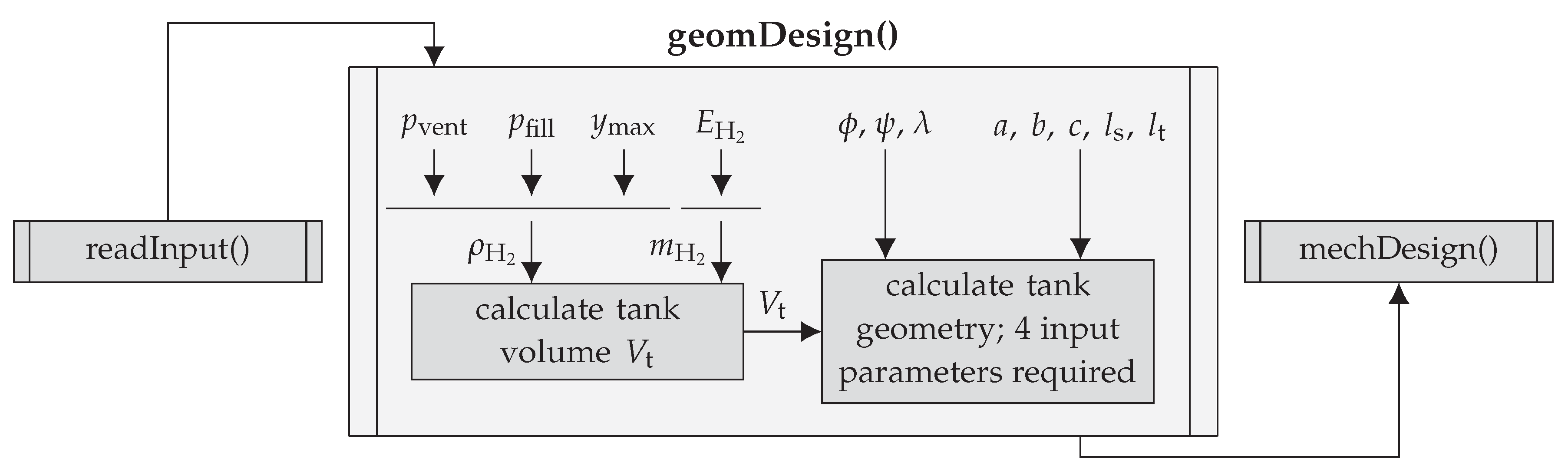
To summarise the relations and procedures introduced in the previous paragraphs about the geometric design, the flowchart in Figure 5 illustrates the input and output parameters and some sub-functions. The mechanical design is introduced in the next section.
2.2.4. Mechanical Design
In the literature, numerous studies address materials for cryogenic applications, e.g., [4,7,17]. Considering the low temperatures of saturated hydrogen and the risk of hydrogen permeation into the tank-wall material, this choice is of crucial importance. In the case of aerospace applications, the material ought to be preferably light, as well to keep the fuel demand as low as possible. A material demanding in parallel a high strength, stiffness and fracture toughness is desirable. However, a material is not available today that combines all these properties satisfactorily. The following paragraphs give firstly a brief overview about material options, before selecting the final tank-wall material and discussing the tank-wall thickness calculation.
Tank-Wall Material
Mital et al. [4] performed a study comparing different materials including characteristics in allowable stress, density and critical crack size. In terms of cryogenic applications, the last two concerns have a significant effect on the performance of the storage system. Mital et al. [4] suggest monolithic metals, continuous-fibre-reinforced polymer matrix composites (PMCs) and discontinuous reinforced metallic composites (DRXs) to be considered, if a practical application is applied. In general, the composite materials have issues with different coefficients of thermal expansion (CTE) and permeation by hydrogen. Robinson [18] reported that the latter is not believed to be a technical barrier for unlined composite tank walls, which would also enable significant weight savings compared to their monolithic counterparts. In any case, in future aircraft applications, the performance of cryogenic storage systems and therefore of the whole aircraft can be improved sufficiently by using tailored composite materials. Because of less experience with composite materials in cryogenic pressure vessels and the resulting high safety factors, which might increase the tank-wall mass significantly, a monolithic metal is chosen in this work. These materials are well-characterised by their properties and well known for their characteristics throughout many applications. In a study by NASA [7], the aluminium alloy 2219 is considered as the tank material, which fulfils all requirements in the best way compared to others investigated. This material properties offer at a cryogenic temperature of 20 K a density of and a limited stress of 172.4 MPa under ultimate design conditions.
Calculation of Tank-Wall Thickness
In aircraft applications, one of the main objectives is to minimise weight. Because of the high density of the tank-wall material, the required wall thicknesses are predicted mostly in accordance with official rules. The Guidelines in [19] provide equations determining the minimum required wall thickness induced by internal overpressure. Cylindrical shells are considered according to Equation (1):
The proof pressure is derived from the maximum overpressure p inside the tank by considering a safety factor and, e.g., dynamic loads. Here, the burst pressure is applied as , which is defined by Brewer [7]. Further information about the weld efficiency v, the safety factor S and the allowances and are provided by [19]. K is the limited stress of the material. Considering half the diameter in Equation (1), the minimum wall thickness of a sphere is obtained. Since a general tank design is applied, the wall-thickness calculation of elliptical shells must be covered, as well. In [20], the mean circumferential stress of an elliptical shell is derived according to internal overpressure. This enables a calculation of the minimum required wall thickness for elliptical shells, which is solved iteratively.
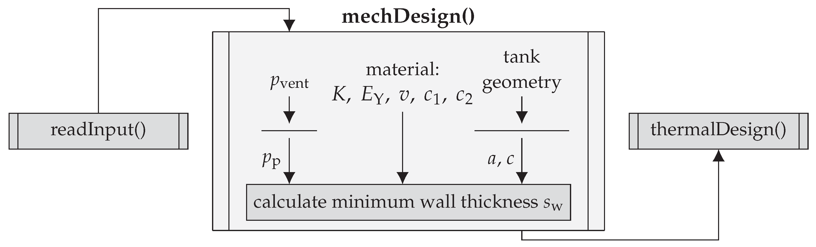
Finally, the flowchart of the mechanical design is schematically shown in Figure 6. The thermal design is introduced after the following paragraph.
Comparison of Tank-Wall Mass
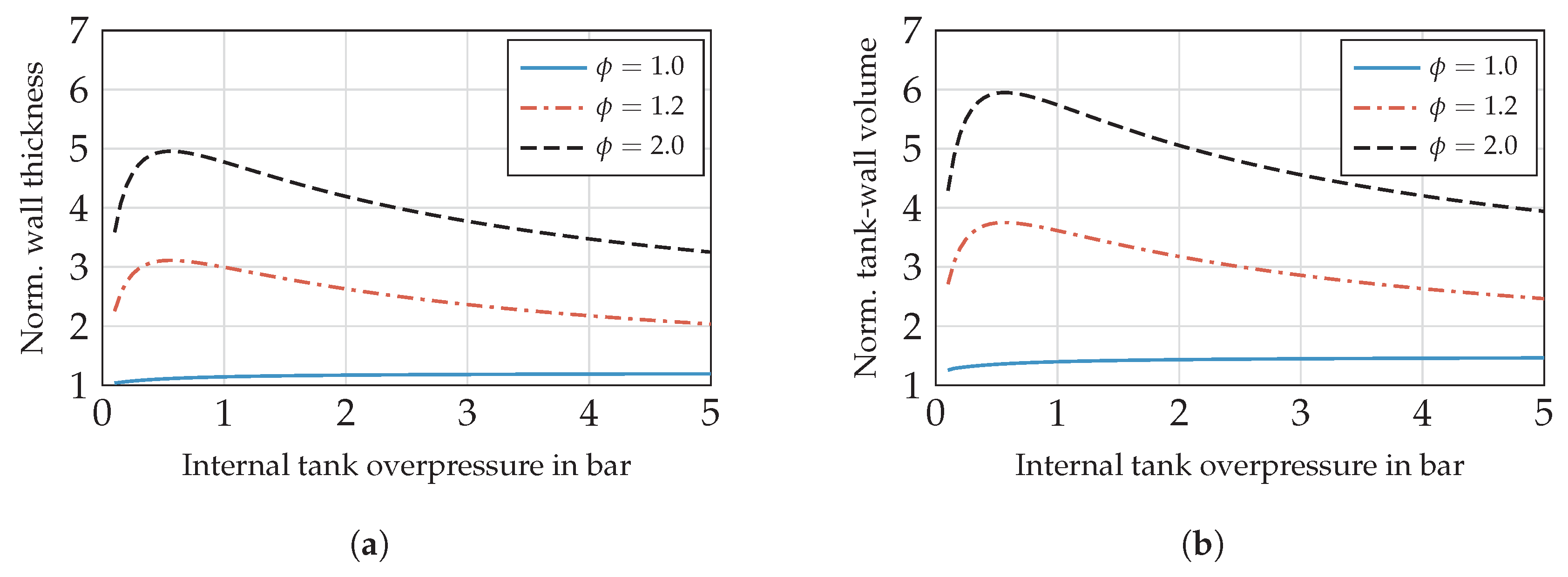
A comparison between different shell designs is discussed qualitatively in this section. In Figure 7a, the tank-wall thickness is shown against the internal overpressure according to Equations (1) and (2) for = [1.0 1.2 2.0] and normalised on a spherical tank design to provide a general assertion independent of the chosen material.
Tank designs with increasing un-roundness () show a tank-wall thickness that is up to five-times higher compared to the sphere (see Figure 7a). A cylindrical shape offers a normalised tank-wall of about 1.1-times thicker. Since the wall thickness does not predict the tank-wall mass directly, the tank-wall volume is evaluated additionally (see Figure 7b). The latter is proportional to the tank-wall mass. The differences in tank-wall volume or mass are even greater, because the non-spherical shapes offer an increased surface-area-to-volume ratio (AVR). From the mass perspective, elliptical tank designs should be avoided.
2.2.5. Thermal Design
The choice of the insulation material or rather the insulation system is an essential factor for the performance of the cryogenic storage system. A tank system that is not able to balance the pressure change caused by heat entering from the environment and fuel consumption might operate at minimum or maximum tank pressure. Therefore, additional heating or venting is required. In aircraft applications generally, a light-weight insulation system is the favoured option, since the direct operating costs are strongly related to the aircraft weight. Finally, the insulation system ought to fulfil strict safety requirements, as well as the capability for comparatively easy maintenance. Before discussing the selection of the insulation system and the modelling approach, a brief overview is given about some available options concerning the insulation in general.
Insulation Materials
Mital et al. [4] give a review of state-of-the-art and key design challenges for insulations in cryogenic environments. Various performance indices are defined to evaluate a wide range of materials and to select the most promising insulation. One of the main issues is to design an insulation system that effectively prevents the air permeating into the insulation. Atmospheric gases would condensate or even solidify at the temperature of liquid hydrogen. To overcome this issue, a vacuum jacket or a system purged by a non-condensable gas, such as helium, is necessary to displace the air. The former solution requires maintaining a vacuum of at least bar to ensure sufficiently low thermal conductivities. Handling the CTE mismatch of the components poses another challenge. Besides these aspects, insulation materials ought to be ascertained, which fulfil the requirements for thermal conductivity , diffusivity a and expansion in the most suitable way possible. In aircraft applications, the insulation must additionally offer a density as low as possible to reduce the fuel demand and the DOCs.
Screening and density properties, polymer foams and aerogels appear to be desirable. Multi-layer insulations (MLIs) provide a similar density compared to foams, while W/mK, which is about two orders less compared to polymer foams. Additionally, polymer foams and aerogels show a low thermal diffusivity of /s. MLIs exhibit a thermal diffusivity of approximately /s.
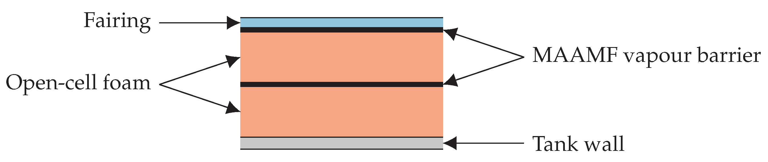
After additionally evaluating the thermal expansion of numerous materials, polymer foams, aerogels and MLI provide sufficient characteristics within the scope of aircraft applications [4]. In the NASA study [7], 15 candidates were screened including the aspects above and construction concepts. In terms of thermal performance and safety aspects, preferred candidates are insulation systems with rigid-cell foam for an integral and non-integral tank design. Furthermore, a hard-vacuum system for the non-integral tank and microspheres evacuated to bar are selected, as well [7]. Verstraete [10] compares a selection of foams and MLIs for the case of a regional and long-range aircraft application. Accordingly, a Rohacell-foam-based insulation system is chosen providing a sufficient advantage in terms of safety aspects ([7,21]) and yielding competitive tank masses compared to MLIs [10]. The structure of the foam-based insulation system including material properties is derived from Brewer [7]. Figure 8 sketches the resulting tank-wall structure based on a non-integrated tank design.
The corresponding properties of the tank-wall material are summarised in Section 2.2.4. Rohacell foam possesses a density of 35.24 and a thermal conductivity approximately between and , which rises with increasing temperature. MAAMF is a multilayer sandwich consisting out of a Mylar layer, followed by two aluminium foils series, another Mylar layer, and a dacron or glass net fabric. The surface density of the MAAMF vapour barrier amounts to 0.225 and its thickness to m. Furthermore, a fairing is applied at the outer surface to prevent the insulation from external damage, which features a surface density of 1.304 and a thickness of m.
Thermal Modelling
While the temperature differs by about 300 K between the inner and outer tank wall, the significant energy input by heat leakage leads to a considerable pressure rise. In this study, the one-dimensional and steady-state heat equation is applied to quantify the heat flux. Convective heat transfer is considered at the inner and outer tank surface and thermal conduction through the insulation and tank wall. A resulting temperature distribution is shown schematically in Figure A1. In the following paragraphs, the calculation of the heat transfer coefficient h is discussed. The heat flux is then calculated by using the thermal resistance R obtained by the heat transfer coefficient h and the corresponding surface area S:
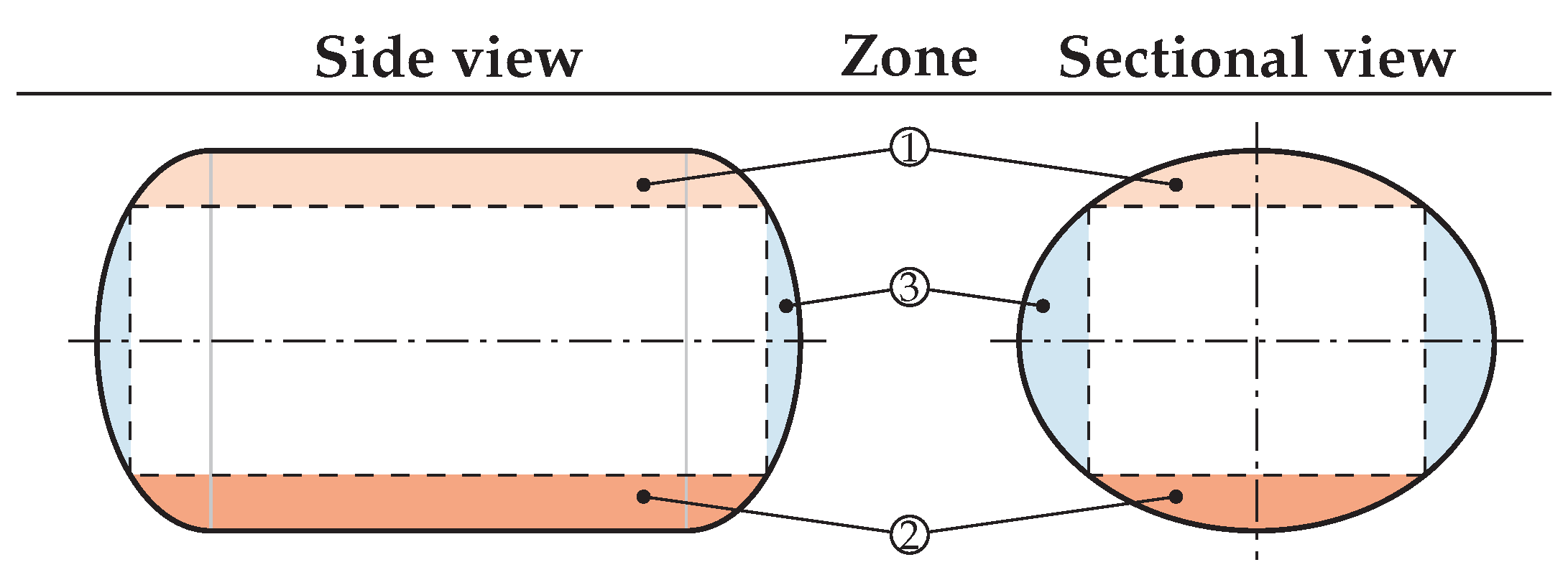
- Internal ConvectionNatural convection is applied to the internal tank surface, because a notable forced fuel-flow is not considered for the internal heat transfer. Furthermore, the natural convection is treated differently within the zones sketched in Figure 9.In the listing below, the approach to calculate the Nusselt number, which is required for determining the heat transfer coefficient within each zone, is discussed.
- Zone 1: The tank wall is heated, resulting in a generally stable boundary layer at its lower side. Here, a correlation for the Nusselt number is applied by Raithby and Hollands [22].
- Zone 2: In contrast to Zone 1, the boundary layer is destabilised at the upper side of the heated tank wall. This aspect is considered by Churchill and Chu [23] for the laminar and turbulent regime.
- Zone 3: A correlation for vertical plates is proposed by Fujii and Imura [24].
Once the Nusselt number and heat transfer coefficient of the liquid phase are known within each zone, the overall heat transfer coefficient of is calculated byis the wetted area of the liquid (index l) and gas (index g). To the gaseous phase, a constant Nusselt number is applied [7]. Therefore, a summation of the individual weighted coefficients of the liquid and gaseous phase yields the total heat transfer coefficient of the internal convection with - External Convection and RadiationConsidering forced convection to the outer tank surface, correlations for the Nusselt number are given for the laminar regime by Pollhausen [25] and Kroujiline [26] and for the turbulent one by Gnielinski [27]. Additionally, heat transfer by radiation is considered, as well. A heat transfer coefficient is calculated according to Baehr and Stephan [28]. The sum of the radiative and convective heat transfer coefficients yields the overall external heat transfer coefficient.
- Thermal ConductionThe thermal conductivity of the foam depends on the foam temperature. Consequently, the foam insulation is separated into several layers to gain reasonable results. The thermal conductivity of the tank-wall material remains constant.
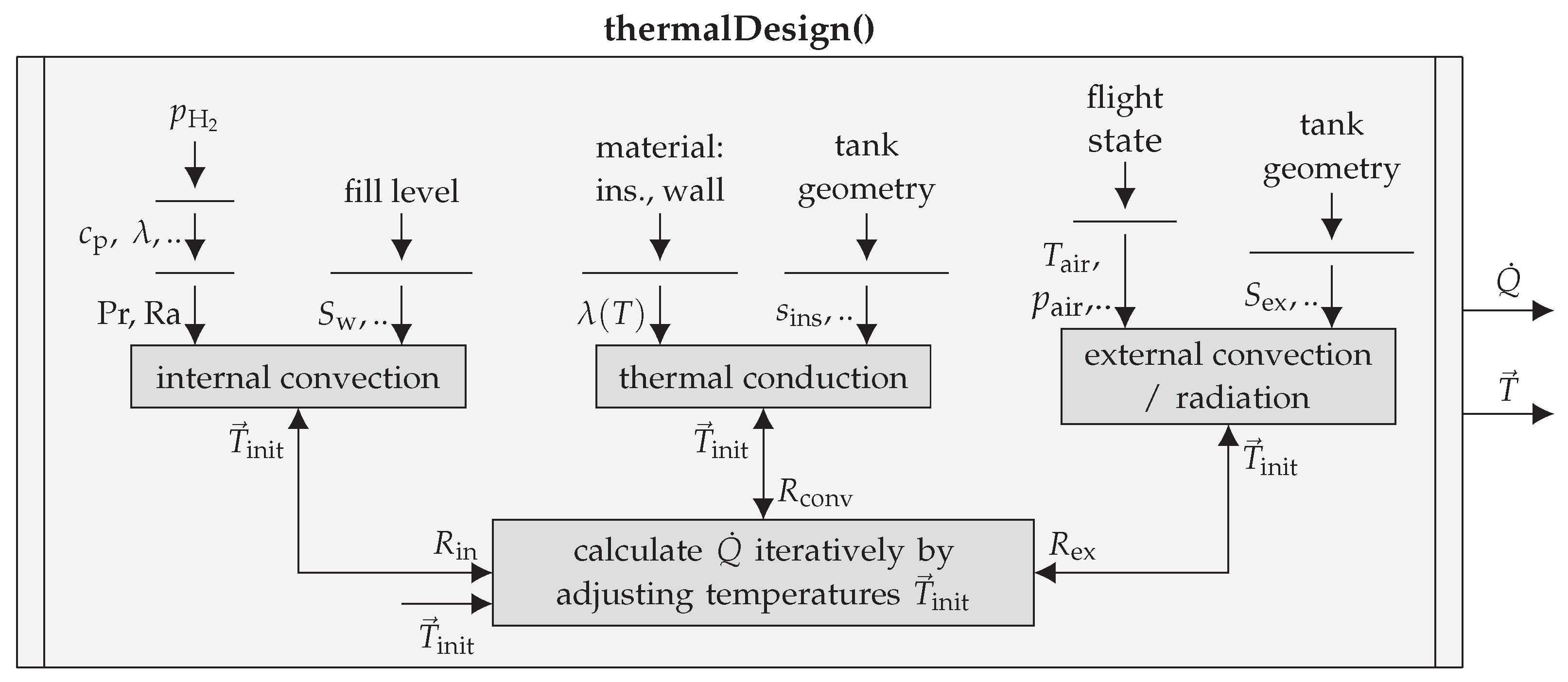
Considering the heat transfer coefficients introduced in the previous paragraphs, the linear system of equations is established (see Equation (A1)). Though the heat transfer coefficients depend non-linearly on the temperature, the unknown temperatures ought to be solved iteratively. A flowchart in Figure 10 shows the thermal design. Based on the tank geometry and the internal and external conditions (hydrogen and air properties), the heat flux is determined. contains the temperatures shown in Figure A1.
2.2.6. Internal Pressure Change
Throughout the flight, the pressure inside the tank may rise due to heat leakage. It might occur as well that the pressure drops while the fuel is withdrawn. To predict the pressure change inside the tank, Lin et al. [29] introduce a homogeneous model assuming liquid-vapour content in homogeneous state. The model equations are obtained by applying the first law of thermodynamics and the conservation of mass. Furthermore, the internal energy u is a function of the density and pressure p. Because the tank volume remains constant and refuelling is not considered during the flight, the pressure change is given by
with the density ratio defined by .
The derivation on the right hand side of Equation (6) yields the pressure change for a certain amount of energy input per density. quantifies the power input by heat flux. Whereas energy is withdrawn via venting or consumption in the fuel cell by the amount of with a certain vapour mass fraction x. In context of a phase equilibrium, the density and internal energy equal the mean properties of the fluid in two-phase conditions. Nevertheless, a homogeneous model under-predicts the pressure change rate, because no degree of stratification is considered. For this reason, Lin et al. [29] used twice the pressure change rate provided by the homogeneous model in Equation (6), which also applies to the model of this study.
The operation management is chosen according to Verstraete [10] allowing a fluctuating pressure during the study mission. Depending on whether the pressure rise or the pressure drop prevails, the internal tank pressure might reach the maximum or minimum allowable value. If the system operates at maximum and venting pressure, respectively, gaseous hydrogen must be vented. In case of operating at minimum pressure, additional energy is necessary to boil off the liquid hydrogen and consequently to keep the pressure from dropping further. The operation procedure regarding tank pressurisation is discussed more in detail in [7].
2.2.7. Study Mission
Determining the pressure change by use of Equation (6) requires information about the heat flux and the hydrogen mass drawn from the tank . For this reason, a study mission is provided for a medium-haul flight including a 30-min hold period before departure and after landing. The heat flux is obtained from the related altitude profile together with an atmospheric temperature model giving the ambient temperatures and pressures. While the hydrogen is stored under cryogenic conditions, the pressure development inside the tank depends highly on the temperature outside of the tank. Therefore, extreme atmospheric conditions in terms of ambient temperature are assumed. By selecting the Tropical Maximum Standard Atmosphere, the ground temperature at departure and arrival is set to 313.15 K with a temperature gradient of 0.0065 K/m. The troposphere commences not until 11,540 m and shows a constant temperature of 243.15 K. Compared to the International Standard Atmosphere (ISA) model, the ground temperature is exceeded by 15 K, and the temperature gradient remains the same.
A proton-exchange membrane fuel-cell (PEMFC) consumes hydrogen and converts its energy to supply the propulsion system with power. Based on the fuel flow of the conventional aircraft, the corresponding hydrogen mass flow is calculated for the same shaft power compared to the conventional case. In general, the current density of a PEMFC rises with the power delivered. The greater the current density increases, the more considerable is the cell voltage and efficiency drop due to internal loss mechanisms. For this purpose, an analytical model is applied to cover these characteristics. This chosen PEMFC model is as simple as possible while still covering all relevant processes in physically meaningful, macroscopic parameters [30]. Figure 11a shows the resulting electric efficiency of the fuel cell in dependence of the normalised power. With the efficiency curve of the fuel cell and the shaft power of the medium-haul flight, the required chemical power can be calculated (see Figure 11b). Dividing by the heat of combustion of hydrogen (see Table 1) determines the required hydrogen mass flow .
2.2.8. Design Process
Combining the modules of geometric, mechanical and thermal design, as well as the transient pressure change model with an exemplary study mission, the hydrogen storage is dimensioned with regard to a set of input parameters. The flight profile determines the initial hydrogen mass , which is required throughout the flight for propulsion. Additional fuel mass ought to be stored, if a certain mass is vented. Consequently, defines the fuel weight and denotes the ratio between required and total fuel mass. Since weight is an important measure in aircraft design, a mass-based evaluation parameter appears to be a suitable choice. To compare different tank designs, a dimensionless parameter with
is suggested by Verstraete [10], which relates the fuel mass to the sum of fuel mass and tank mass . The latter is defined as the sum of insulation mass and tank-wall mass . Here, a different, but more informative evaluation parameter is introduced in Equation (8) with
Based on the required energy, the dimensionless storage density is used as a figure of merit enabling a suitable comparison between different tank designs. Basically, is the product from and . Especially, the parameter depends strongly on the insulation performance, because it indirectly provides the share of vented mass in total hydrogen mass. In general, an evaluation of the storage energy density is addressed for various tank designs.
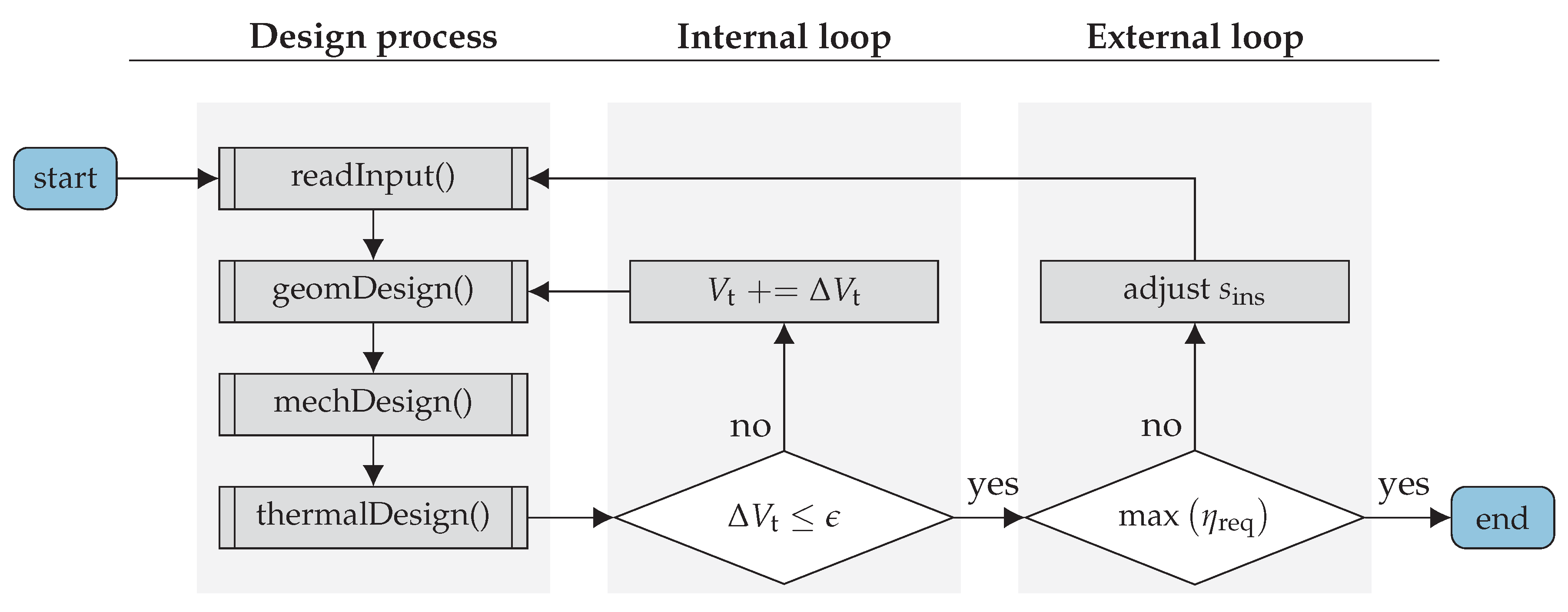
While this procedure is straight forward so far, an internal and external loop extends the design process. Figure 12 shows the flowchart of this tank modelling program. The internal loop adjusts the tank volume, if the fuel mass changes in order to compensate venting losses. equals , while the unit of is . Proceeding from a given set of geometric parameters, the minimum required thickness of the insulation cannot be calculated analytically. During the design process, the maximiser is to be found in order to maximise , for which the outer loop is integrated. The MATLAB internal function fmincon serves as the solver to maximise . The step size tolerance for the maximiser and the function tolerance of is set to .
3. Results
In this section, the model is applied to, on the one hand, a parameter variation to gain general information about the tank design. On the other hand, the hydrogen storage is split into a certain number of tanks to elaborate on the associated disadvantages. Whereas these results are obtained by use of the mission profile given in Section 2.2.7, an additional variant of this scenario is analysed, which assumes changes in the mission parameters. Since the cryogenic tank design is most sensitive to the duration of exposure to ambient temperatures, the hold time before the flight is shortened and extended.
3.1. Geometrical Parameter Variation
In contrast to most of the previous studies on hydrogen storage, which discuss a dimensioning on particular aircraft geometries, our approach is a more fundamental one: here, the tank design is evaluated over a wide range of the dimensionless parameters , and to draw general conclusions on the effect of shapes of tanks. With regard to the significant influence of on the tank-wall volume (as seen in Figure 7b), this parameter is varied between 0.5 and 1.5. Furthermore, the parameter is considered within a range of . Finally, the parameter completes the set.
3.1.1. Single Tank
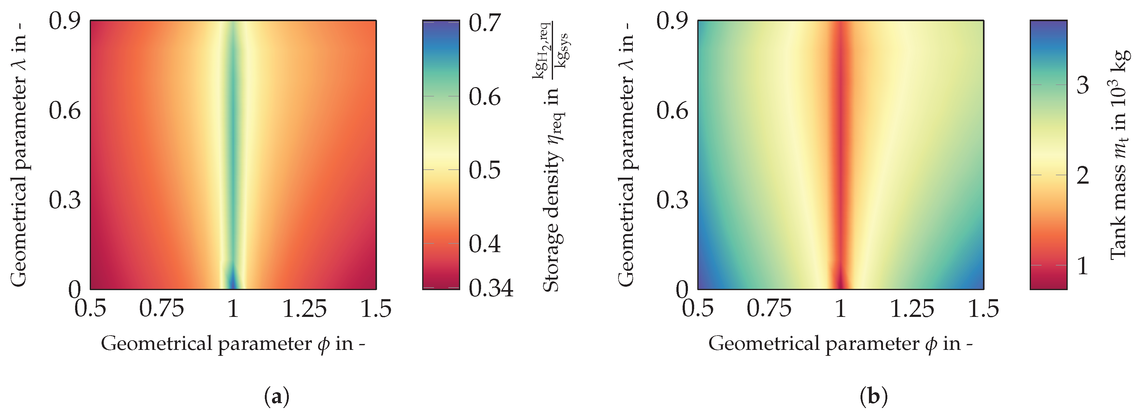
Proceeding with the evaluation of this study for a single tank solution, Figure 13a shows the storage density against and .
In total, a range in from 0.34 up to 0.7 is covered, which means that the required hydrogen mass has a maximum share of the total system mass of nearly 70%. This value applies for a spherical tank showing a considerable advantage in wall volume. As indicated in Section 2.2.4, cylindrical shells () exhibit superior storage densities compared to elliptical shapes. The former provide values for above 0.6 for the complete range of . For slightly un-round shells, the storage density decreases remarkably. Along the parameter , the sensitivity on the storage density is significantly smaller.
A qualitatively similar characteristic is shown in Figure 13b, which plots the tank mass, including insulation and wall mass, against the geometrical parameter and . Cylindrical shells offer a tank weight of about kg, which rises significantly up to kg for elliptical shells. The gradients from cylindrical to elliptical shells, as well as for increasing shell length behave similar to the observation in the previous paragraph. These sensitivities of the particular geometric parameters are investigated further in the next sections.
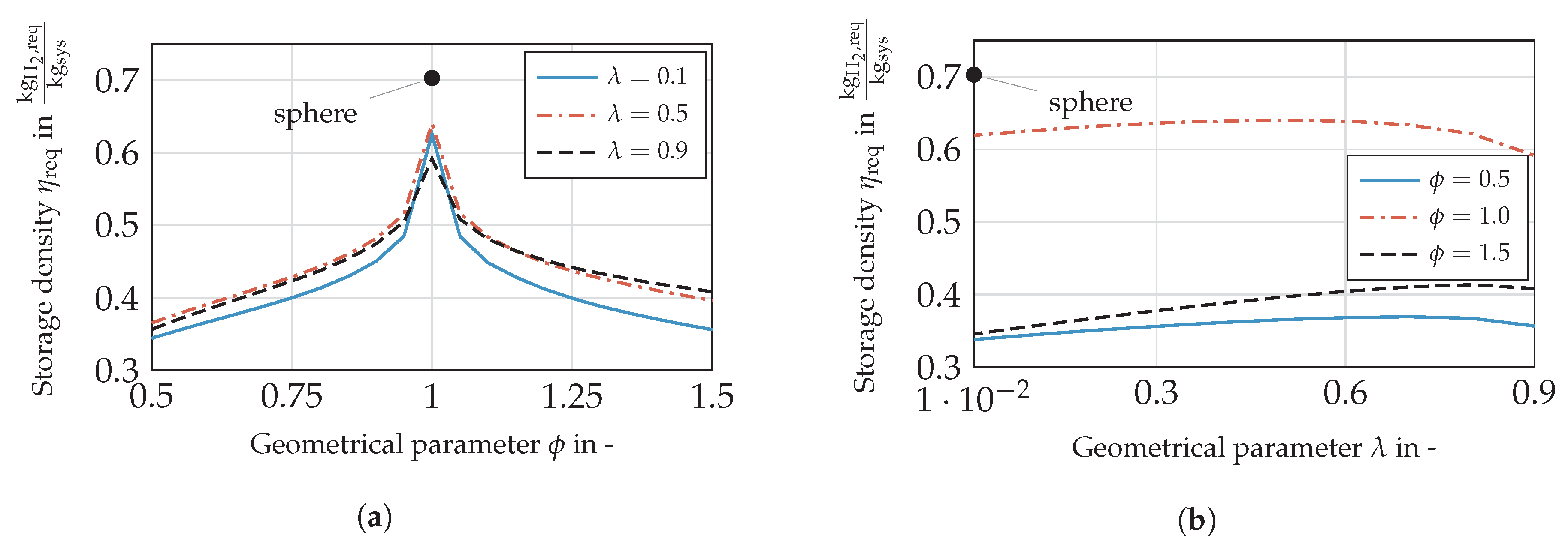
Dependency of on ϕ
Figure 14a shows the storage density in dependence of for a selection of . For comparison, the sphere is added, which shows a discontinuity in tank-wall thickness and therefore in storage density (see Equation (1)). Changing the parameter diminishes up to 23%. Slightly elliptical shells ( = 1.2) show a significant higher tank-wall mass compared to cylindrical ones (as seen in Figure 7). As a result, the wall thickness is highly responsible for this significant gradient. Increasing the un-roundness further the sensitivity on drops, which is also referable to the wall mass. Towards a greater un-roundness in general, the tanks are geometrical similar for and . Differences in storage density are referable to the change rates in the wetted area of the gaseous and liquid hydrogen dependent on the filling level. Consequently, the pressure fluctuations obtain various temporal progresses leading to a different thermal design.
Dependency of on λ
Figure 14b shows the storage density against for exemplary values of . In contrast to the sensitivity on , the parameter shows significantly less impact on . Starting from a cylindrical shell, the storage density differs by 10% over the range investigated, for by , and exhibits a deviation of with regard to the maximum.
For a cylindrical shell (), the optimum design lies within a flat maximum at . While increasing the un-roundness, the maximum shifts toward () and (), respectively. Picking up the motivation of this study, a particular range of is preferable, if the overall mass is the parameter to minimise. Although cylindrical shells are the most advantageous design option in terms of mass, the designs should feature a certain overall tank length.
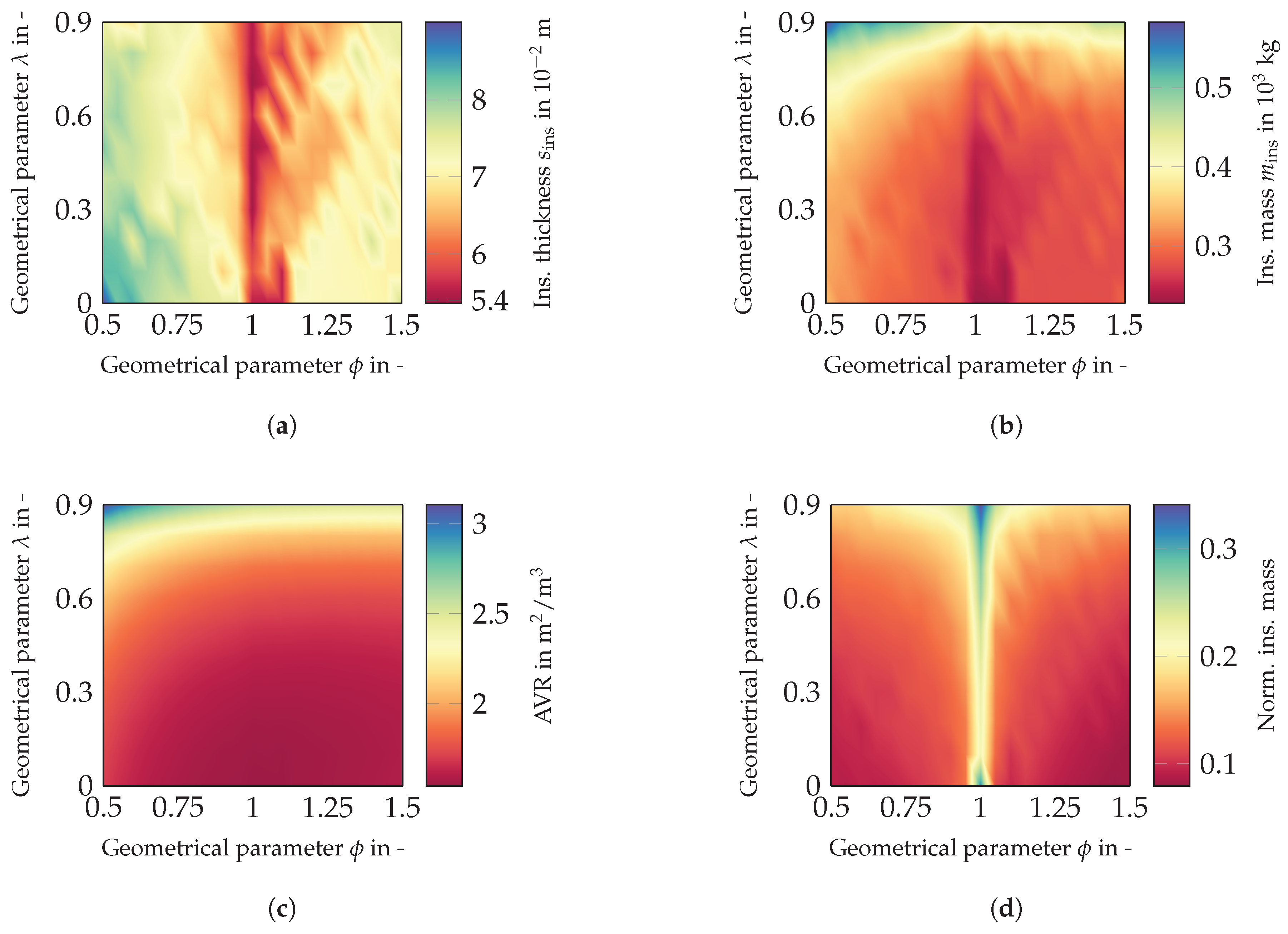
Considering additionally Figure 15, it can be seen that designs with low lambda allow one to decrease the insulation mass that is needed (Figure 15b). This occurs despite that the tank diameter increases for more compact tanks, resulting in thicker walls. Although, longer tanks () provide slight differences in insulation thickness according to Figure 15a. Still, the insulation mass is far greater compared to compact tanks, because of the considerable disadvantage in surface-area-to-volume ratio. Consequently, the impacts of insulation and wall mass possess opposite signs and lead to a lower sensitivity on compared to .
Dependency of Geometric Parameters on
Larger insulation thicknesses can be observed for designs with decreasing and increasing un-roundness. Since designs of less provide greater wall thicknesses resulting from increased diameters (see Figure 4), the sensitivity on the overall mass is considerably high. Allowing a certain amount of venting, the wall mass would rise remarkable to the rise in volume. Furthermore, the density of the wall material () exceeds the density of the insulations material () by two orders of magnitude. The point where the insulation thickness is the main driver in storage density change lies towards thicker insulations rather than for designs providing smaller tank diameters. The same applies for designs with a considerable un-roundness.
The insulation mass depends directly on the AVR (see Figure 15b,c). The overall change in AVR is greater than change in , so that the absolute insulation mass is in favour of the AVR. Nonetheless, the tank mass is mainly driven by the wall mass as shown in Figure 15d. This is because, on the one hand, the insulation mass only amounts to 10%–35% of the tank mass. On the other hand, the qualitative characteristic of the normalised insulation mass is similar to the absolute insulation mass, since less insulation mass comes along with smaller shares of the total mass, but mainly driven by the tank-wall mass.
Furthermore, compact geometries providing a superior AVR do not represent the best options in terms of storage density (see Figure 15c). With regard to their comparatively thick walls resulting from increased diameter, they offer considerably lower storage densities. From this study, tank designs with between 0.6 and 0.8 are suggested in order to minimise the tank mass compared to the required fuel mass. The spherical design marks an exception according to a less thick wall and offers the highest storage density. Generally, cylindrical shells show their advantage compared to elliptical ones.
Dependency of on Storage Density and Venting
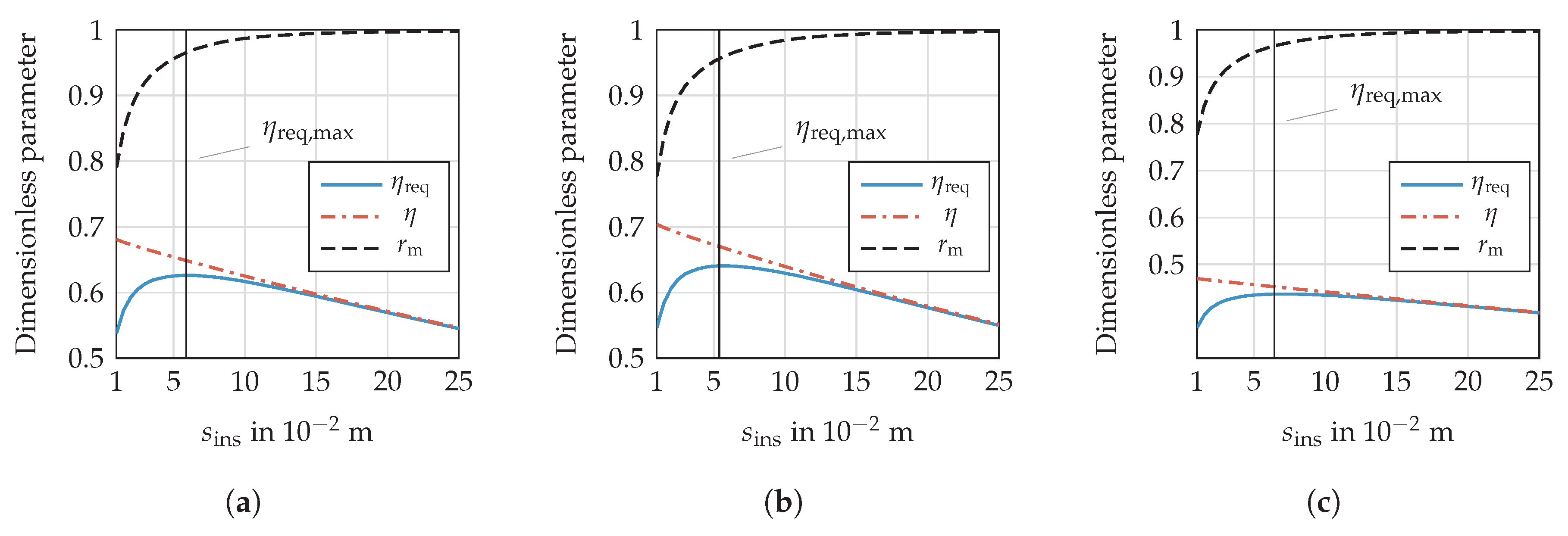
As the top-down approach discussed the results of the parameter study only, a brief, more in depth view shows the dependency of the insulation thickness on the storage density with an example. Figure 16 illustrates , and over a certain range of the insulation thickness for selected parameters.
Whenever fuel is vented, the ratio of fuel mass and total mass () is higher than (storage density), because the total hydrogen mass exceeds the required fuel mass by the amount of . Furthermore, maximising the storage density is not essentially associated with kg, if the boundary conditions basically allow a certain amount of venting. A share in the order of 1–5% of the vented losses in the total hydrogen mass leads to an optimum design regarding the storage density. As indicated in Figure 16, the curve is flat around the maximum characterises , which offers some scope in designing the insulation system. To illustrate this behaviour by some examples, Figure 16 shows storage densities as a function of the insulation thickness for three parameter sets. The plots in Figure 16a,b differ in the value of , whereas Figure 16c shows an increased , but with the same as the plot in Figure 16b.
Especially for greater , the maximum becomes even flatter, so that the tolerance in the outer design loop ought to be significantly less. Nonetheless, proceeding from the maximum, the vented hydrogen mass rises significantly less towards thicker than thinner insulations. Consequently, highly under-estimated heat leakage might result in considerable boil-off losses, which decrease the available fuel mass, as well, if the tank is designed close to this critical gradient.
Interim Conclusion
To sum up, introducing materials for the mechanical design superior in density and strength in cryogenic environments promises great enhancement in tank weight due to noticeably high density and shares on the overall tank weight. Especially compact designs will gain the most benefit by improving the tank-wall material. Otherwise, longer tanks possess a greater share of the insulation mass in overall tank weight. Cylinders offer a comparable high share of approximately 30% in insulation mass, because the wall thickness is less compared to elliptical shells. The latter otherwise show shares between 10% and 20%. Improving the insulation system would lead to a considerable increase in for those geometries.
3.1.2. Multiple Tanks
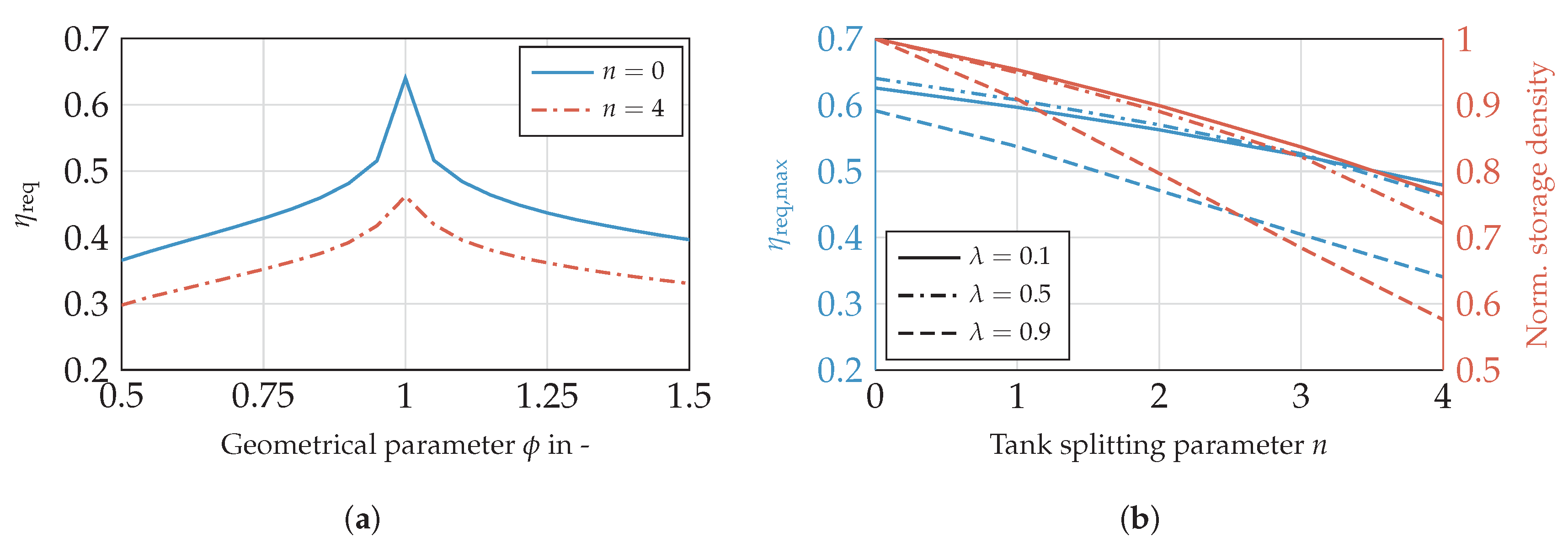
For geometrically-similar designs, a decrease in volume correlates with an increase in AVR in general. Therefore, a higher share of insulation mass on tank mass is expected. A volume variation is performed to investigate this effect. The power profile (see Figure 11b) is multiplied by the factor with n = 0, 1, …, 4. For constant n, each tank stores the same amount of energy, and the fuel is withdrawn equally. Consequently, the ratio between volume and outlet mass-flow remains constant. For assessing the impact of multiple tanks, the storage density of the single tank () in the previous section can directly be compared to the multiple tank solution. Figure 17 addresses the comparison of the single and multiple tank solution with regard to .
Figure 17a plots the storage density against . The loss in storage density is highest for cylindrical shells when storing the fuel in various tanks; this holds as well relatively. Since the reduction in tank-wall mass is considerable less compared to elliptical tanks, this effect does not compensate the disadvantage along with increasing AVR and accordingly in insulation mass. Nevertheless, is still the favourable option. The density is lower at all for the split tank version, because the AVR gains increasingly more impact when reducing the overall tank size. Therefore, designs providing a higher AVR in general suffer the most with regard to the storage density (). This trend is more clearly shown in Figure 17b, where the absolute maximum storage density and the change in maximum storage density normalised on are plotted and evaluated for different and . The advantage of longitudinal tanks compared to compact designs is outweighed by the disadvantages associated with increasing n. While increasingly compact designs are affected less by a tank splitting, the optimal value for shifts towards zero. Although the design with and shows less storage density than the tank with , it provides the smallest change rate, leading to a more competitive design for increasingly smaller tanks.
Splitting or rather reducing the tank size decreases the storage density over the whole range of the screened parameters. Further investigations appear to be thinkable against the background that multiple tank solutions are feasible with regard to various operating strategies. For example, a different withdrawal of the fuel might be advantageous in terms of tank insulation design, balancing the filling or the pressure levels, can be suitable as well. Though these hypotheses are not part of the present study, this should trigger further investigations.
3.2. Hold Time
Since the pressure development inside the tank depends on the heat input, reducing the time on the ground appears to be desirable. For this reason, the impact of the hold time before departure and after arrival is investigated. Commencing with the time period before the flight, Figure 18a shows , and against various times.
The curves drop approximately linearly over the time investigated. With longer hold times, decreases from 95.9%–94.4%. Therefore, a rising amount of venting is accepted as opposed to a further increase in insulation thickness, in order to maximise the storage density. Since more fuel mass is stored, decreases as well. Combining and , the storage density decreases from 0.648–0.623 .
Figure 18b,c plots against the hold time before departure and after arrival, respectively. The design with shows the most significant drop in storage density, because it provides a comparatively high AVR. The other two curves behave equally, featuring a similar gradient. In addition, the hold time after arrival affects the storage density similar to the time before departure. Only the curve for shows a slightly higher gradient. Since the tank is almost empty, the vapour mass fraction is significantly greater than provided by a refuelled tank. The derivation (see Equation (6)) is less for gaseous hydrogen, meaning a smaller amount of energy is required for a certain pressure rise compared to liquid.
This evaluation shows that reducing the hold time leads to less tank and fuel weight. Beside from an exclusive aircraft-related tank design, improving the turn-around time on ground is additionally desirable from this perspective.
3.3. Comparison to Kerosene Tanks
To put the presented results in context, the liquid hydrogen tanks are compared to kerosene tanks in terms of energy density and mass. Based on the presented results, an exemplary cylindrical hydrogen tank () can achieve a storage density of around 0.64. This corresponds to a gravimetric energy density of approximately 21 kWh/kg, which is significantly above 8.9 kWh/kg obtained by kerosene tanks. Although the tank reduces the effective energy density of hydrogen stronger compared to kerosene tanks (), the storage density is still 2.35-times higher. Besides the advantage in gravimetric density of hydrogen, the fuel savings by applying a fuel cell must be taken into account, as well. According to the mission profile in this study, the required hydrogen mass of 1912 kg is only 28% of the required kerosene mass, which amounts to 6890 kg. Consequently, the mass of the storage system including mass of kerosene (9187 kg) is nearly three-times the mass of the system (2988 kg). Although further requirements, such as maintaining cryogenic temperatures inside the tank, safety periphery and heat exchangers, are not covered here, tanks are highly competitive with kerosene tanks. If future materials are applied, the gravimetric energy density improves further.
Comparing the densities of liquid hydrogen and kerosene, the volume of is 11.4-times the volume of kerosene for the same mass. Applying the fuel mass, which is required for the exemplary mission, the factor is reduced to 3.34. Here, a mean density of 67.3 kg/ for hydrogen is chosen considering the gas fraction available for venting. The higher gravimetric energy density and the efficient fuel cell reduce the disadvantage in required hydrogen volume significantly. Although the volume is still tripled compared to kerosene, this technical challenge is manageable while introducing new airframe concepts.
4. Conclusions
In this study, a design tool for cryogenic hydrogen tanks is presented. Analysis of the sensitivity of the storage density shows the importance of using specific design missions for tank design and considering the hydrogen mass required for venting. Therefore, cryogenic hydrogen tanks ought to be tailored to a specific application, including new aircraft designs, as well as flight missions. This applies, because the insulation design depends on the overall mission profile. Additionally, the tank weight has a considerable share of the fuel weight.
Finding a universal solution in overall tank design is more challenging compared to kerosene tanks, because of the insulation design, which is influenced by numerous factors. This might result in over-sizing the insulation system for some applications. Therefore, an important aspect for future research is the investigation of tank structure integration into the airframe to reduce the disadvantage in unified thermal systems and increasing the energy density. Nonetheless, cryogenic hydrogen storage and a fuel cell-supplied propulsion system appear to be superior to the conventional system with regard to mass that has to be considered for storage. The disadvantage of liquid hydrogen compared to kerosene with regard to volume ought to be investigated in the context of the whole aircraft design. Although the integration of hydrogen tanks into common aircraft appears to be challenging or even inappropriate, future aircraft will be designed to accommodate new storage technologies. For this reason, further investigations covering the whole propulsion system are highly suggested under consideration of new design approaches.
Acknowledgments
We would like to acknowledge the support of the Ministry for Science and Culture of Lower Saxony (Grant No. VWZN3177) for funding the research project “Energy System Transformation in Aviation” in the initiative “Niedersächsisches Vorab”. Further acknowledgements go to Bekir Yildiz for providing the authors with the mission data.
Author Contributions
Christopher Winnefeld programmed the design tool, produced and analysed the results and wrote the main parts of the manuscript; Thomas Kadyk applied the analytic fuel cell model and was involved in advising during the study. Boris Bensmann elaborated the story line and objectives of the study together with Christopher Winnefeld and contributed in a large part to critical discussions. Ulrike Krewer and Richard Hanke-Rauschenbach contributed by drafting and critical revisions.
Conflicts of Interest
The authors declare no conflict of interest.
List of Symbols
The following symbols are used in this manuscript:
| Variables | ||
| Symbol | Unit | Meaning |
| a, b, c | m | ellipsoidal axis |
| , | m | allowance |
| d | m | diameter |
| E | J | energy |
| Young’s modulus | ||
| f | - | relative filling level |
| h | heat transfer coefficient | |
| J/kg | heat of vapourisation | |
| K | limited stress | |
| l | m | length |
| m | kg | mass |
| kg/s | mass flow | |
| n | - | tank-splitting parameter |
| N | - | number of insulation layer |
| p | pressure | |
| P | J/s | power |
| J/s | heat flux | |
| r | - | ratio |
| R | K/W | thermal resistance |
| s | m | thickness |
| S | - | safety factor |
| S | surface area | |
| wetted surface area | ||
| t | s | time |
| T | K | temperature |
| u | J/kg | internal energy |
| v | - | veld efficiency |
| V | volume | |
| x | - | vapour mass fraction |
| y | - | liquid volume fraction |
| - | difference | |
| - | tank-volume tolerance | |
| storage density | ||
| - | geometric parameter | |
| thermal conductivity | ||
| - | electric efficiency | |
| density | ||
| - | density ratio | |
| Subscripts | ||
| Symbol | Meaning | |
| 1, 2, 3 | running index | |
| c | critical point | |
| conv | convection | |
| ex | external | |
| f | fuel | |
| fill | filling | |
| g | gaseous | |
| i | running index | |
| in | internal | |
| ins | insulation | |
| l | liquid | |
| m | mass | |
| max | maximum | |
| min | minimum | |
| out | outlet | |
| p | proof | |
| req | required | |
| s | shell | |
| sys | system | |
| t | tank | |
| vent | venting | |
| w | wall | |
| Abbreviations | ||
| Symbol | Meaning | |
| AVR | surface-area-to-volume ratio | |
| CTE | coefficients of thermal expansion | |
| DOC | direct operating cost | |
| gaseous hydrogen | ||
| ISA | international standard atmosphere | |
| liquid hydrogen | ||
| MLI | multi-layer insulation | |
| PEMFC | proton-exchange membrane fuel-cell |
Appendix A
In Figure A1, the layer arrangement of the tank structure and exemplary temperature distribution within the tank wall and insulation are shown. Furthermore, the different types of heat transfer are illustrated, i.e, the convective and conductive heat transfer.
Figure A1.
Schematic layer arrangement and prior temperature distribution for .

In Equation (A1), the linear system of equations is shown to obtain the heat flux.
References
- Boeing. Current Market Outlook 2017–2036; Boeing: Chicago, IL, USA, 2017. [Google Scholar]
- Airbus. Global Market Forecast: Growing Horizons 2017–2036; Airbus: Toulouse, France, 2017. [Google Scholar]
- European Commission. Flightpath 2050: Europe’s Vision for Aviation; European Commission: Brussels, Belgium, 2011. [Google Scholar]
- Mital, S.K.; Gyekenyesi, J.Z.; Arnold, S.M.; Sullivan, R.M.; Manderscheid, J.M.; Murthy, P.L.N. Review of Current State of the Art and Key Design Issues with Potential Solutions for Liquid Hydrogen Cryogenic Storage Tank Structures for Aircraft Applications; National Aeronautics and Space Administration: Cleveland, OH, USA, 2006.
- Colozza, A.J. Hydrogen Storage for Aircraft Applications Overview; NASA CR-2002-211867; National Aeronautics and Space Administration: Cleveland, OH, USA, 2002.
- Gong, A.; Verstraete, D. Fuel Cell Propulsion in Small Fixed-Wing Unmanned Aerial Vehicles: Current Status and Research Needs. Int. J. Hydrogen Energy 2017, 42, 21311–21333. [Google Scholar] [CrossRef]
- Brewer, G.D. Hydrogen Aircraft Technology, 1st ed.; CRC-Press: Boca Raton, FL, USA, 1991. [Google Scholar]
- Brewer, G.D.; Morris, R.E. Final Report: Study of LH2 Fueled Subsonic Passenger Transport Aircraft; NASA CR-144935; National Aeronautics and Space Administration: Cleveland, OH, USA, 1976.
- Airbus. Liquid Hydrogen Fuelled Aircraft—System Analysis; Airbus: Toulouse, France, 2003. [Google Scholar]
- Verstraete, D. The Potential of Liquid Hydrogen for Long Range Aircraft Propulsion. Ph.D. Thesis, Cranfield University, Cranfield, UK, 2009. [Google Scholar]
- Peters, R. Brennstoffzellensysteme in der Luftfahrt, 1st ed.; Springer: Berlin/Heidelberg, Germany, 2015. [Google Scholar]
- Heinze, W.; Hansen, L.U.; Werner-Spatz, C.; Horst, P. Gesamtentwurfsuntersuchungen zu BWB- Frachtflugzeugen mit alternativen Treibstoffen. In Proceedings of the Deutscher Luft- und Raumfahrtkongress, Aachen, Germany, 8–10 September 2009. [Google Scholar]
- Smith, H. Airframe Integration for an LH2 Hybrid-Electric Propulsion System. Aircr. Eng. Aerosp. Technol. Int. J. 2014, 86, 562–567. [Google Scholar] [CrossRef]
- NIST. Thermophysical Properties of Fluid Systems; National Institute of Standards and Technology: Gaithersburg, MD, USA, 2017.
- Sehra, A.K.; Whitlow, W., Jr. Propulsion and Power for 21st Century Aviation. Prog. Aerosp. Sci. 2004, 40, 199–235. [Google Scholar] [CrossRef]
- Leachman, J.W.; Jacobsen, R.T.; Penoncello, S.G.; Lemmon, E.W. Fundamental Equations of State for Parahydrogen, Normal Hydrogen, and Orthohydrogen. J. Phys. Chem. Ref. Data 2009, 38, 721–748. [Google Scholar] [CrossRef]
- Züttel, A. Materials for Hydrogen Storage. Materialstoday 2003, 6, 24–33. [Google Scholar] [CrossRef]
- Robinson, M.J.; Eichinger, J.D.; Johnson, S.E. Hydrogen Permeability Requirements and Testing for Reusable Launch Vehicle Tanks. In Proceedings of the 43th AIAA/ASME/ASCE/AHS/ASC Structures, Structural Dynamics And Materials Conference, Denver, CO, USA, 22–25 April 2002. [Google Scholar]
- Dampfkesselausschuss, D. Technische Regeln für Dampfkessel; Verband der TÜV e.V.: Berlin, Germany, 2010. [Google Scholar]
- Schwaigerer, S.; Mühlenbeck, G. Festigkeitsberechnung, 5th ed.; Springer: Berlin/Heidelberg, Germany, 1997. [Google Scholar]
- Anthony, F.M.; Colt, J.Z.; Helenbrook, R.G. Development and Validation of Cryogenic Foam Insulation for LH2 Subsonic Transports; National Aeronautics and Space Administration: Cleveland, OH, USA, 1981.
- Raithby, G.D.; Hollands, K.G.T. Natural Convection. In Handbook of Heat Transfer, 3rd ed.; Rohsenow, W.M., Hartnett, J.P., Cho, Y.I., Eds.; McGraw: New York, NY, USA, 1998; Chapter 4. [Google Scholar]
- Churchill, S.W.; Chu, H.H.S. Correlation Equations for Laminar and Turbulent Free Convection from a Vertical Plate. Int. J. Heat Mass Transf. 1974, 18, 1323–1329. [Google Scholar] [CrossRef]
- Fujii, T.; Imura, H. Natural-Convection Heat Transfer From a Plate with Arbitrary Inclination. Int. J. Heat Mass Transf. 1972, 15, 755–767. [Google Scholar] [CrossRef]
- Pollhausen, E. Der Wärmeaustausch zwischen festen Körpern und Flüssigkeiten mit kleiner Reibung und kleiner Wärmeleitung. J. Appl. Math. Mech. 1921, 2, 115–121. [Google Scholar] [CrossRef]
- Kroujiline, G. Investigation de la couche-limite thermique. Tech. Phys. USSR 1936, 3, 183–194. [Google Scholar]
- Gnielinski, V. Berechnung mittlerer Wärme- und Stoffübergangskoeffizienten an laminar und turbulent überstömten Einzelkörpern mit Hilfe einer einheitlichen Gleichung. Forsch. Ingenieurwes. 1975, 41, 145–153. [Google Scholar] [CrossRef]
- Baehr, H.D.; Stephan, K. Wärme- und Stoffübertragung, 9th ed.; Springer: Berlin/Heidelberg, Germany, 2016. [Google Scholar]
- Lin, C.S.; Van Dresar, N.T.; Hasan, M.M. A Pressure Control Analysis of Cryogenic Storage Systems. J. Propuls. Power 1991, 20, 480–485. [Google Scholar] [CrossRef]
- Kulikovsky, A.A. A Physically–Based Analytical Polarization Curve of a PEM Fuel Cell. J. Electrochem. Soc. 2014, 161, F263–F270. [Google Scholar] [CrossRef]
Figure 1.
(a) The saturation curve of para-hydrogen is shown. (b) The density of liquid and gaseous para-hydrogen in saturation state is plotted.
Figure 1.
(a) The saturation curve of para-hydrogen is shown. (b) The density of liquid and gaseous para-hydrogen in saturation state is plotted.

Figure 2.
(a) The mean storage density is shown against pressure for for saturation conditions. (b) The liquid volume fraction is shown against tank pressure for various venting pressures with (following [10]).
Figure 2.
(a) The mean storage density is shown against pressure for for saturation conditions. (b) The liquid volume fraction is shown against tank pressure for various venting pressures with (following [10]).

Figure 3.
Nomenclature describing the geometric tank design.

Figure 4.
(a) The tank design depends on with (). (b) The tank design depends on with (). (c) The tank design depends on with ().
Figure 4.
(a) The tank design depends on with (). (b) The tank design depends on with (). (c) The tank design depends on with ().

Figure 5.
Flow chart of the geometric design.

Figure 6.
Flow chart of mechanical design.

Figure 7.
(a) The minimum wall thickness is shown against the internal tank overpressure with , , and . (b) The normalised tank-wall volume is shown against the internal tank overpressure with , and .
Figure 7.
(a) The minimum wall thickness is shown against the internal tank overpressure with , , and . (b) The normalised tank-wall volume is shown against the internal tank overpressure with , and .

Figure 8.
Non-integral structure of a foam-based insulation derived from Brewer [7].
Figure 8.
Non-integral structure of a foam-based insulation derived from Brewer [7].

Figure 9.
Geometric breakdown of the tank geometry.

Figure 10.
Flow chart of thermal design.

Figure 11.
(a) The electric fuel-cell efficiency is shown against normalised electrical power. (b) The required chemical power is illustrated against flight time.
Figure 11.
(a) The electric fuel-cell efficiency is shown against normalised electrical power. (b) The required chemical power is illustrated against flight time.

Figure 12.
Flow chart of the tank modelling program with the insulation thickness , change in tank volume and tank-volume tolerance .
Figure 12.
Flow chart of the tank modelling program with the insulation thickness , change in tank volume and tank-volume tolerance .

Figure 13.
(a) Storage density is shown against the design parameters and . (b) Tank mass is shown against the design parameters and .
Figure 13.
(a) Storage density is shown against the design parameters and . (b) Tank mass is shown against the design parameters and .

Figure 14.
(a) The dependency of storage density on is shown. (b) The dependency of storage density on is shown. of a sphere () represents a benchmark in both sub-figures.
Figure 14.
(a) The dependency of storage density on is shown. (b) The dependency of storage density on is shown. of a sphere () represents a benchmark in both sub-figures.

Figure 15.
(a) The insulation thickness is covered over the parameter variation. (b) The insulation mass is investigated against and . (c) The surface-area-to-volume ratio is investigated over the parameter variation. (d) The normalised insulation mass is investigated against and .
Figure 15.
(a) The insulation thickness is covered over the parameter variation. (b) The insulation mass is investigated against and . (c) The surface-area-to-volume ratio is investigated over the parameter variation. (d) The normalised insulation mass is investigated against and .

Figure 16.
(a) The dependency of storage density on for is shown. (b) The dependency of storage density on for is shown. (c) The dependency of storage density on for is shown.
Figure 16.
(a) The dependency of storage density on for is shown. (b) The dependency of storage density on for is shown. (c) The dependency of storage density on for is shown.

Figure 17.
(a) The comparison between of single and multiple tank solution () is shown for . (b) The maximum storage density and change in storage density is investigated ().
Figure 17.
(a) The comparison between of single and multiple tank solution () is shown for . (b) The maximum storage density and change in storage density is investigated ().

Figure 18.
(a) The dependency of , and on hold time before departure is shown (). (b) The dependency of storage density on hold time before departure is shown for various (). (c) The dependency of storage density on hold time after arrival is shown for various ().
Figure 18.
(a) The dependency of , and on hold time before departure is shown (). (b) The dependency of storage density on hold time before departure is shown for various (). (c) The dependency of storage density on hold time after arrival is shown for various ().


© 2018 by the authors. Licensee MDPI, Basel, Switzerland. This article is an open access article distributed under the terms and conditions of the Creative Commons Attribution (CC BY) license (http://creativecommons.org/licenses/by/4.0/).
Share and Cite
MDPI and ACS Style
Winnefeld, C.; Kadyk, T.; Bensmann, B.; Krewer, U.; Hanke-Rauschenbach, R. Modelling and Designing Cryogenic Hydrogen Tanks for Future Aircraft Applications. Energies 2018, 11, 105. https://doi.org/10.3390/en11010105
AMA Style
Winnefeld C, Kadyk T, Bensmann B, Krewer U, Hanke-Rauschenbach R. Modelling and Designing Cryogenic Hydrogen Tanks for Future Aircraft Applications. Energies. 2018; 11(1):105. https://doi.org/10.3390/en11010105
Chicago/Turabian StyleWinnefeld, Christopher, Thomas Kadyk, Boris Bensmann, Ulrike Krewer, and Richard Hanke-Rauschenbach. 2018. "Modelling and Designing Cryogenic Hydrogen Tanks for Future Aircraft Applications" Energies 11, no. 1: 105. https://doi.org/10.3390/en11010105
Note that from the first issue of 2016, this journal uses article numbers instead of page numbers. See further details here.