A Novel Transmit–Receive System of Frequency Diverse Array Radar for Multitarget Localization


State Key Laboratory of Complex Electromagnetic Environment Effects on Electronics and Information System, National University of Defense Technology, Changsha 410000, China
*
Author to whom correspondence should be addressed.
Electronics 2018, 7(12), 408; https://doi.org/10.3390/electronics7120408
Submission received: 16 November 2018
/
Accepted: 27 November 2018
/
Published: 7 December 2018
(This article belongs to the Section Microwave and Wireless Communications)
Abstract
:The frequency diverse array (FDA) has drawn substantial attention because it provides a new degree of freedom. However, the multitarget localization is fundamentally limited by the range-angle-coupled and range-periodic beampattern of the basic FDA. It has been suggested to design a special FDA configuration to localize targets, but seldom of the existing works consider the design both in transmitting and receiving. In this paper, a transmit–receive system of FDA radar is proposed for the multitarget localization. In order to decouple the beampattern in the range and angle domains, the configurations of subarray-based FDA (SB-FDA) and full-band FDA (FB-FDA) are chosen as transmitter and receiver, respectively. In such a system framework, the receive beamwidth in range domain is only a quarter of the transmission. Then, two typical multitarget scenarios, sparse targets and unresolved targets, are both considered in the multitarget localization. For sparse targets, a proper frequency increment is selected to control the range-periodic transmit and receive mainlobes to focus on a single target, besides being staggered with others. In this way, multitarget localization is achieved in different pulses with monopulse processing. For unresolved targets, a method of intra-pulse beam scanning is proposed to localize each target with little interference from others. We also analyze the system performance in Cramér-Rao lower bound (CRLB) of localization and output signal to interference-plus-noise ratio (SINR). Several simulation results demonstrate the effectiveness of the proposed transmit–receive system in multitarget localization.
1. Introduction
Frequency diverse array (FDA), initially designed and experimentally tested in [1], has attracted much attention due to the angle-range-dependent beampattern in recent years. Unlike the conventional phased array, whose beam steering is fixed at one angle for all range, FDA can form a range-dependent beampattern with its additional degree of freedom. A tiny frequency increment is introduced among the elements, so that FDA has great potential in the joint estimation of target’s range and angle [2,3]. Even though several approaches [4,5,6,7] are proposed for target range-angle localization, most of them fail in the case of multiple targets since the peaks of the basic FDA are range-angle-decoupled and range-periodic. Especially, when two or more targets are located in the same angle, range and Doppler resolution cell (i.e., unresolved targets), the estimated location will be far away from either true target due to the “merged” measurement [8]. How to achieve the multitarget localization on FDA radar is still an open issue.
To improve the multitarget localization performance, it is suggested to adopt a specially designed FDA configuration to decouple the beampattern in range and angle domains [9]. On this basis, many approaches have been proposed which can be divided into two categories. One category is to design the frequency increment or transmit weight, such as logarithmical frequency increment [10,11,12], window-based frequency increment [13], coding modulated frequency increment [14], optimized frequency increment by Genetic algorithm [15] and optimized transmit weight by compression sensing [16,17]. However, the beampatterns of such approaches are subject to quantization error. Moreover, the nonlinear frequency offsets add a great complexity to the subsequent signal processing. The other category is to design the array configuration. Subarray-based FDA (SB-FDA) is proposed to decouple transmit beampattern in [18] where the whole array is divided into symmetric subarrays with opposite frequency increments. Full-band FDA (FB-FDA) [19] is a spacial receive architecture which produces a range-angle-decoupled beampattern. Different from the basic FDA, each element of FB-FDA connects with a comb filter bank to receive all return signals including transmitted by other elements. By comparison, the second category of approaches has an advantage on beamforming since the weight optimization is not necessary. Even though the configurations of SB-FDA and FB-FDA are more complex, the linear frequency offsets help to apply classical algorithms of the phased array, like monopulse technique [20].
Based on a specially designed FDA system, the multitarget localization is achieved by several approaches. In [21], SB-FDA is used to estimate the covariance matrix by subaperture smoothing. Multiple targets can be localized by multiple signal classification (MUSIC), but the resolution performance is seriously limited by subaperturing. In [9], multiple targets are imaged by a nonuniform FDA transmitter and uniform phased array receiver. Note that, the results of [9,21] are both ambiguous in range because the peaks of beampattern are still range-periodic. To overcome this limitation, an unambiguous localization is achieved by combining FDA and multiple-input multiple-output (MIMO) in [22,23]. By using the coprime FB-FDA, multitarget localizaiton is achieved within the Bayesian compressive sensing framework in [24]. The result is also unambiguous because the unambiguous range is extended largely by the coprime elements. However, the unambiguous approaches require a large number of snapshots and computational cost to achieve a good performance. It means that they may fail without enough available snapshots and computing resource, which is common in the radar application. Furthermore, the localization performance will get much worse when multiple targets are unresolved.
Indeed, the FDA radar can measure one target in a single pulse and measure the other one in the next pulse like the multitarget tracking of the phased array radar. In this sense, the number of shapshots and computational cost are no longer problems. However, unlike the phased array radar, the range-periodic peaks of FDA beampattern are unavoidable. Moreover, the resolutions of FDA radar in range and angle are inversely proportional to total coherent bandwidth and array aperture, respectively, but the resolution is difficult to be improved in a lone detection range. That is to say, multiple targets may be located in the same mainlobe. Thus, there are two main issues regarding multitarget localization: (1) The range-periodic peaks will result in range ambiguity for the sparse targets; (2) The merged measurement of unresolved targets will result in a large estimation error.
Unlike the conventional phased array, the receive beamwidth of FDA in the range domain is much narrower than transmit due to the double propagation range. The joint design for transmitting and receiving is much beneficial to the multitarget localization, especially to the unresolved targets, but most existing works only focus on the transmit or receive. In this paper, we design a novel transmit–receive system of FDA radar for multitarget localization. Our contributions are summarized as follows: (1) By combining the configurations of SB-FDA and FB-FDA, the receive beamwidth of system in range is only one quarter of transmit; (2) Considering two typical multitarget scenarios, sparse targets and unresolved targets, we propose frequency increment selection and intra-pulse beam scanning to localize them with a few, or even one single, pulse(s). Note that the combination of SB-FDA and FB-FDA is similar to the system configuration we proposed in [20] but is not identical, which can localize one target only. In this sense, the proposed transmit–receive FDA system is the development of [20] in multitarget scenario.
The remaining sections are organized as follows. The transmit–receive system configuration of FDA radar is introduced in Section 2. Then, two multitarget localization methods are proposed in Section 3. We also analyze the system performance in Cramér-Rao lower bound (CRLB) of localization and output signal to interference-plus-noise ratio (SINR) in Section 4. Simulation results are provided in Section 5. Finally, conclusions are drawn in Section 6.
2. System Configuration
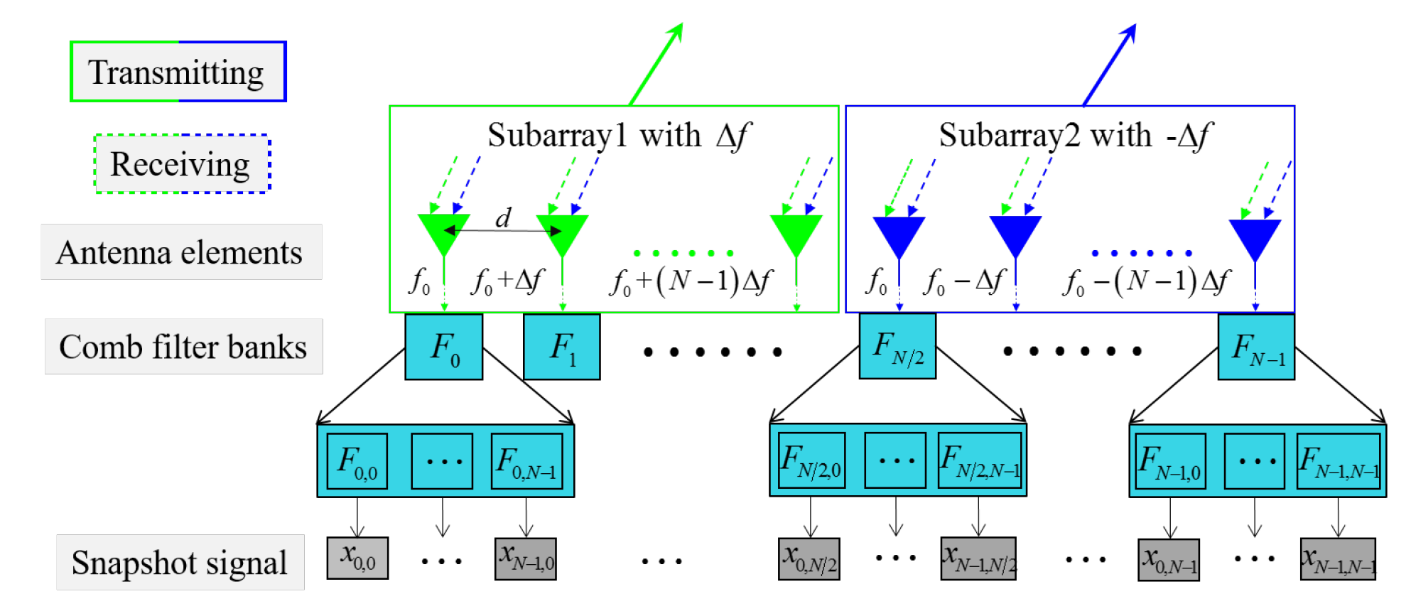
The transmit–receive system configuration of the FDA radar is shown in Figure 1. SB-FDA and FB-FDA are used as the transmitter and receiver, respectively, to decouple the beampatterns in range and angle domains. The whole array is divided into two equal-length subarrays to transmit waveforms with a pair of opposite frequency increments.
2.1. Transmit Beampattern
Considering a linear uniform array with elements, two opposite frequency increments are and . The radiate frequency of the th element is
where denotes the carrier frequency and . In far-field condition, the transmit steering vectors of two subarrays are expressed as [18]
where . r and u denote the range and the sine of angle. Subscript i denotes the index of subarray. c is the light speed and d is the element spacing. In the sequel, taking the array center as phase reference, the total steering vector is given as
where denotes phase factor between subarrays and is the conjugate. Assuming the region of interest is at , the transmit weight vector can be constructed as
where and . Therefore, the transmit beampattern focused at is expressed as
where is the Hermitain transpose. and can be written as
Since two subarrays with opposite frequency increments are equal-length, the S-shape beampatterns of subarrays are symmetrical. Note that the total transmit beampattern is the sum of two subarrays. Therefore, the range-periodic peaks only exist in the direction , namely, the transmit beampattern is range-angle-decoupled.
When , the total transmit beampattern is approximated as
It is observed that the 3 dB-beamwidth of transmit in range domain is and the repetition period of peaks is .
2.2. Receive Beampattern
FB-FDA is used to receive here. The filtered signal transmitted by element and received by element is expressed as
where and . when and when . Note that, compared with transmitting, the phase term of range is double when receiving.
Under the complex weighs , the receive beampattern is expressed as
Similar to transmit beampattern, the receive beampattern is also the sum of two subarrays. and can be written as
The receive beampattern of FB-FDA is decoupled in range and angle domains since it’s the sum of different S-shape beampatterns. Similar to transmit beampattern, the range-periodic peaks only exist in the direction .
When , the receive beampattern is approximated as
It can be seen that the 3 dB-beamwidth of receive beampattern in range domain is and the repetition period of peaks is . Therefore, we have
In summary, the transmit and receive beampatterns of system are both range-angle-decoupled. Besides, is only one quarter of . It is mainly because that the subarray-based transmit configuration results in a half of transmit aperture meanwhile the whole aperture is used to receive. In addition, the propagation range of waveform when receiving is double of that when transmitting. Such an FDA system with wide transmit beam and narrow receive beam helps to greatly improve the performance of multitarget localization.
3. Multitarget Localization for Sparse Targets and Unresolved Targets
The multifunction phased array radar usually steers the beam to focus on each target in different single pulse or coherent pulses to achieve multitarget tracking [25]. Therefore, for the multitarget localization of FDA radar, it is reasonable to steer the transmit and receive beam like the conventional phased array radar. However, the localization performance is still limited by the range-periodic peaks, and will get worse when multiple targets are unresolved. In this section, the localization methods for two typical multitarget scenarios including sparse targets and unresolved targets.
3.1. Siganl Model
According to the output of FB-FDA, the receive steering vector is expressed as
where denotes the transpose operator.
Assuming there are M targets, the snapshot model is given as
where , and . , and denote the range, angle and complex amplitude of target respectively. is the complex Guassian zero-mean additive white noise vector with identical variance. Set is the variance of noise, the signal noise ratio (SNR) of ith is then defined as .
Assume that the number of targets has been determined. The likelihood function is
The maximum likelihood estimation can be exchanged into an optimization problem [26] expressed as
where , which denotes the amplitude estimate. If only one target detected , (16) is rewritten as
The monopulse technique of FDA [20] can be used for fast target localization in this case. Let , we then have
where and are the partial derivatives, and are the second partial derivatives, and is the mixed partial derivative.
3.2. Frequency Increment Selection for Sparse Targets
Motivated by the phased array radar, for sparse targets, we only need to steer the transmit and receive beams to focus on each target in different pulses. However, if multiple targets are located in different range-periodic mainlobes, localization will fail due to the range ambiguity. A simple approach is to change the range repetition period of beampattern peaks in real time. By selecting a proper frequency increment, only one target is located in the mainlobe. Then, the received power of other targets out of mainlobe will be much lower. In this way, each target can be rapidly localized by (18) in different pulses. That is to say that we only need M pulses to achieve the localization of M targets.
However, there are two constrains in frequency increment selection. One is that the range-periodic peaks of transmit and receive beampatterns should be staggered with other targets. The other one is that the transmit beamwidth in the range domain should be slightly larger than the range resolution of baseband signal. A too narrow transmit beam may lead to missed detection after match filtering [28,29,30].
Assume there are K targets detected in different range cell but the same angle cell. In order to satisfy the first constrain condition, we have
where is the other target’s range is the range repetition period of receive beampattern. Set the signal bandwidth is B. In order to satisfy the second constrain condition, we have
3.3. Intra-Pulse Beam Scanning for Unresolved Targets
Consider M targets located in the same mainlobe. Assume the radar cross sections (RCS) of all the targets are the same. When the transmit beam points to one target completely, the complex amplitude of echo is defined as . Then the complex amplitude of each unresolved target is proportionate to expressed as
If the transmit and receive beams both point to the center of unresolved cell (i.e., the resolution cell containing unresolved targets), the output amplitude of receive beampattern at high SNR is given as
It is observed that targets’ echoes are all strong. When the receive beam points to one target, the power reflected from other targets will turn to sidelobe interference, which results in a heavy measurement error [31]. It means monopulse processing cannot work anymore. For unresolved targets, if the range difference between targets is larger than receive beamwidth, the merged measurement is an issue of sidelobe interference. If not, it is an issue of low resolution.
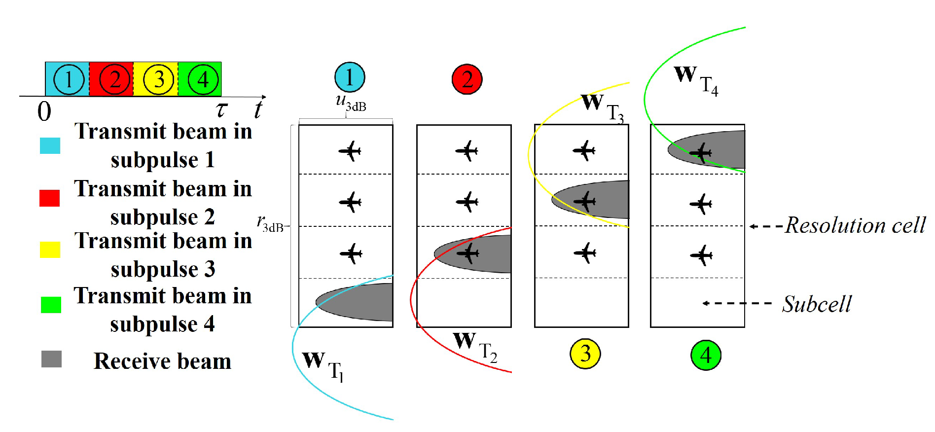
In such a system framework, we can transmit with a wide beam and recieve with a narrow beam. Motivated by the space–time coding technique [32], intra-pulse beam scanning is proposed to improve the localization performance by suppressing sidelobe interference. The main benefit of space-time coding is total instantaneous angular coverage. Indeed, intra-pulse beam scanning a transmit–receive diversity method [33]. The main idea is that the pulse is divided into four subpulses, and the unresolved cell is divided into four subcells. During each subpulse, as shown in Figure 2, we steer transmit beam to focus on one or two subcells only.
The scanning weight vectors are
where .
Under the scanning weights and , the output amplitude changes to
We can see that the targets in other subcells are out of transmit and receive mainlobes. Namely, they are filtered out by the overall transmit–receive (T-R) beam. In this way, each subcell can be measured in different subpulse with little sidelobe interference. Note that we still need to solve (16) if multiple targets are detected in the same subcell. However, the localization performance will be improved greatly because a much high-dimensional nonlinear optimization problem is decomposed to four simple problems.
4. System Performance Analysis
4.1. CRLB
According to (15), the natural logarithm formula of likelihood function is expressed as
The unknown parameters need to be estimate are angle, range. Therefore, the parameter vector is
The Fisher information matrix is derived as
According to the analysis in [34,35], we invert to obtain the CRLB of target’s range and angle
where , and . denotes the real part and ⊙ denotes the Hadamard product.
Finally, the CRLBs with respect to the range and angle of each target is derived. Note that CRLB is determined by two terms, and , which are related to the echo power and the array manifold, respectively. With the transmit–receive beamforming proposed in Section 3, each target can be focused on both by the transmit and receive beams in different pulses. It means the echo power of multiple targets will be all strong. In addition, the localization performance can be improved by raising the frequency increment which is consistent with the conclusions drawn in [4,35], but as shown in (20), the frequency increment is limited by the range resolution of baseband signal.
4.2. SINR Analysis
Our focus here is the output SINR which directly impacts the target localization performance. Suppose that there are M interference sources located at and only one target located in the transmit mainlobe. In this case, the signal model given in (14) is rewritten as
where denotes the complex amplitude of the interference. Assume that the interferences are mutually uncorrelated and stochastic with zero mean and variance , the interference-plus-noise covariance matrix is represented by
The conventional nonadaptive beamforming is known to be optimal in the case that it provides the highest possible output SNR and SINR in the background of white Gaussian noise. Thus, we use the conventional nonadaptive beamforming on the received signal and derive the output SINR. With the receive weight vector , the output SINR of the proposed system can be evaluated by
If the target is detected in the background of a few weak interferences which are well-separated from the target, the noise is dominant in the interference-to-noise power. In this case, SINR is approximated as
Contrarliy, if the target is observed in the background of strong interferences, the interferences are dominant. In this case, SINR is approximated as
It is observed that SINR is related to the location of interference in strong interferences. If the interference is located in the first sidelobe, or even in the range-periodic mainlobe exactly, the output SINR will have a large loss. However, frequency increment selection helps to solve this problem.
5. Simulations and Results
Consider the proposed FDA configuration with elements. The band of transmitted signal is . So the conventional range and angle resolutions are m and . Two scenarios of sparse and unresolved targets are designed, respectively, to verify the effectiveness of the proposed approach.
Example 1 (System performance in the scenario of sparse targets).
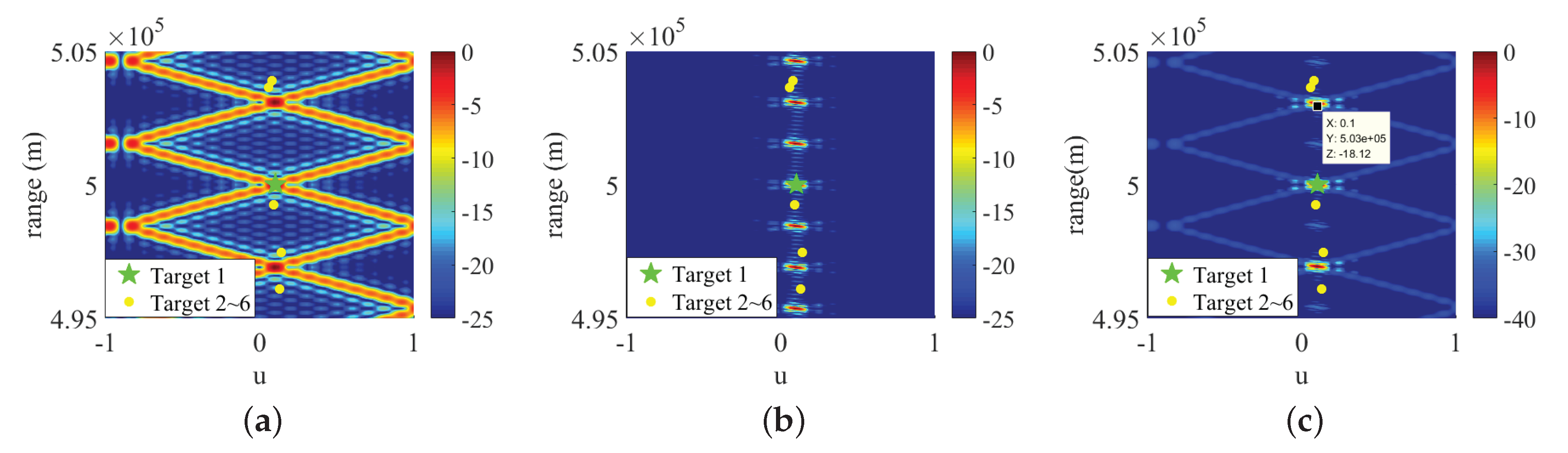
In the first example, we assume that there are targets, where one is located at (500 km, 0.1) and others are located in the same angle but different range cells. Without loss of generality, the locations of other 5 targets are randomly generated under uniform distribution. Table 1 shows one case of sparse taregts.
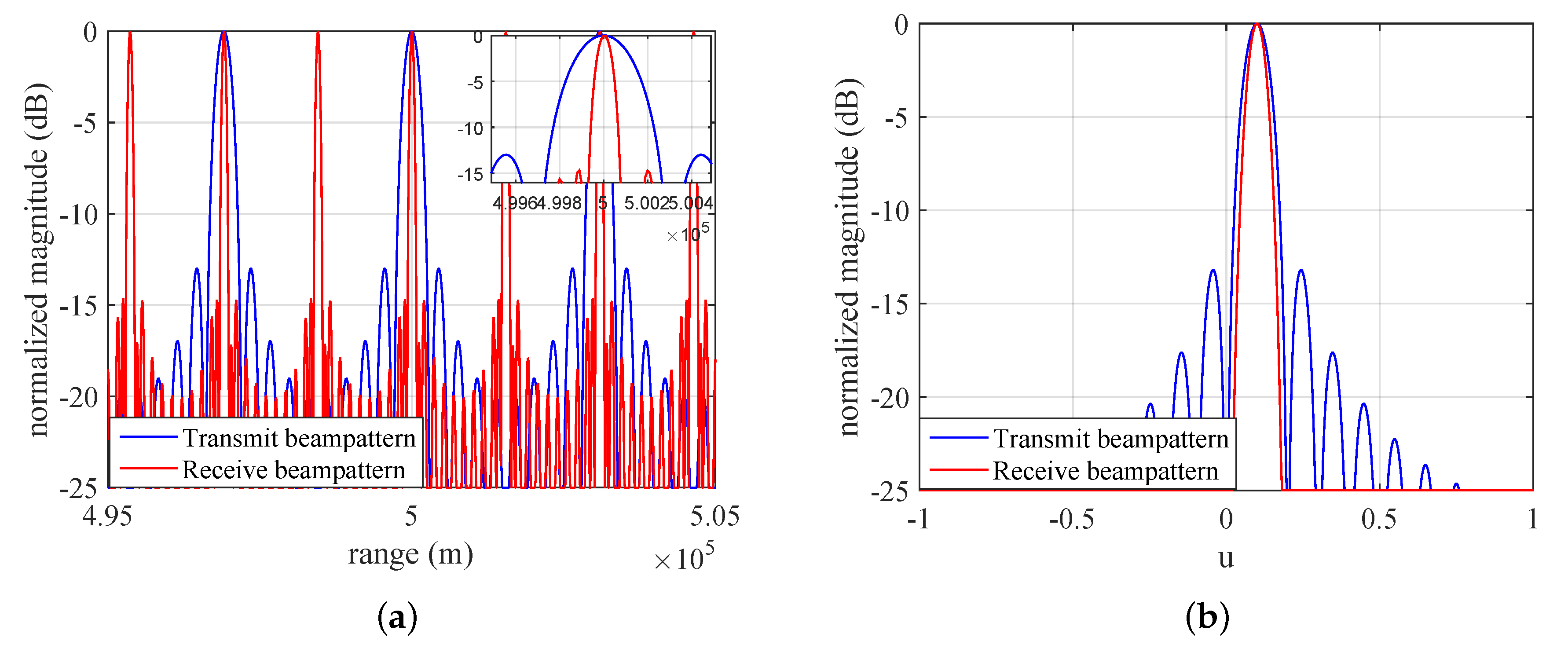
According to (21), the frequency increment is selected as where we set . Figure 3 shows that transmit, receive and overall transmit–receive (T-R) beampatterns all focus on Target 1, besides staggered with other targets. The first sidelobe is about . In this case, estimated range is unambiguous although the peaks are still range-periodic. It means we only need 6 pulses to localize all targets by monopulse processing. In addition, Figure 4 shows the slices of transmit and receive beampatterns in and . Note that, the receive range beamwidth is one quarter of transmit but angle beamwidth is about the same, which is consistent with the analysis in Section 2.
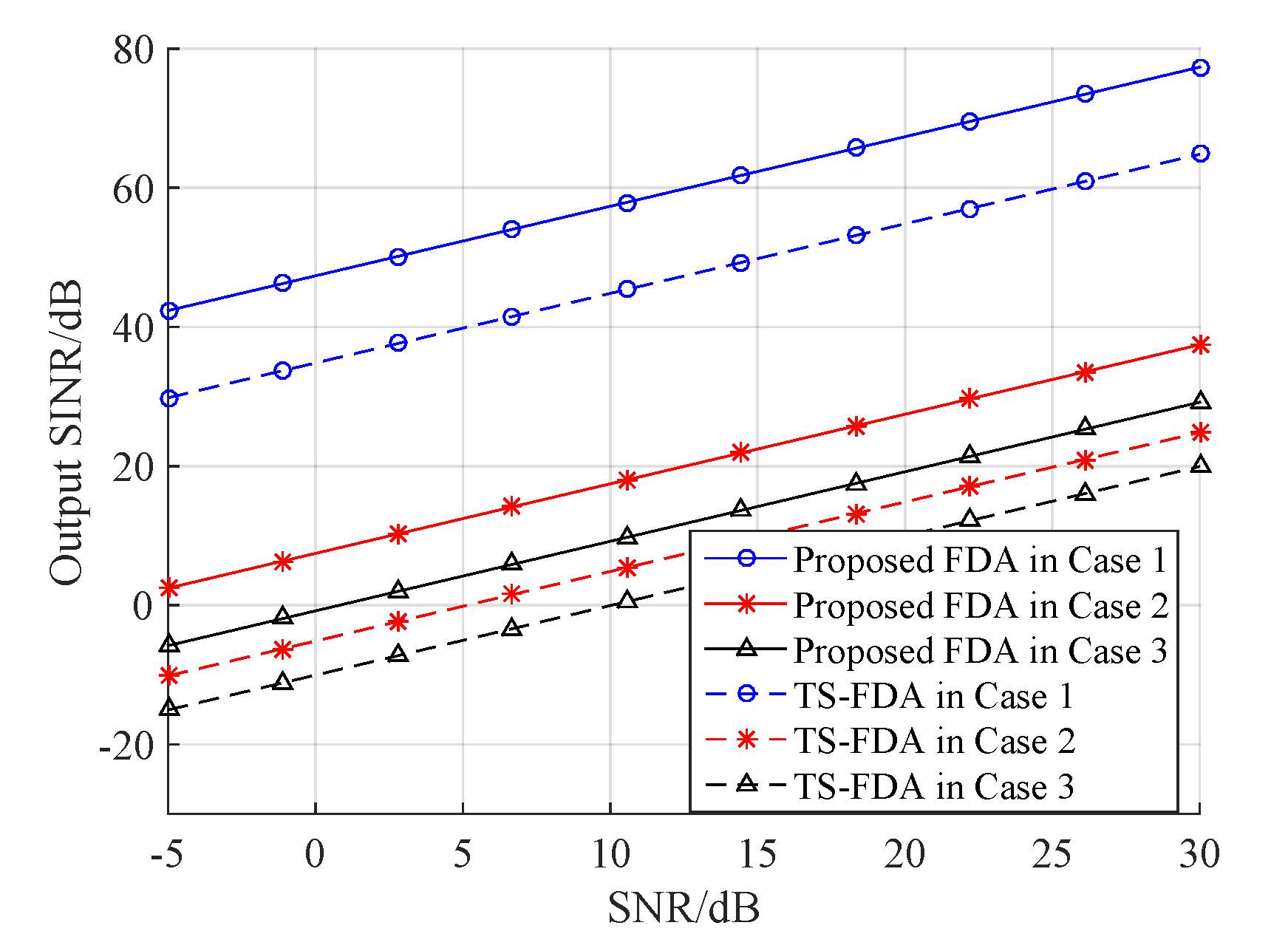
We also examine the output SINR of the proposed system versus SNR. Three cases of interference are set as shown in Table 2. Assume that the transmit and receive beams both focus on Target 1. Three interferences are separated from the target and their powers are equal. The interference locations of Case 1 and Case 2 are the same, but the interference power of Case 2 is much larger. Namely, Case 1 is noise-dominant and Case 2 is interference-dominant. We set the Interference 1 is located in the first sidelobe of receive beampattern in Case 3, which is interference-dominant. Figure 5 shows the output SINRs of the proposed FDA system and the transmit subaperturing FDA (TS-FDA) [21] versus SNR in different cases. It is observed that the proposed system outperforms the TS-FDA in output SINR because all the return signals are received by using the FB-FDA. Note that the proposed system has an equivalent robustness against noise in the noise-dominant case. Furthermore, the range-dependent interference is suppressed in the interference-dominant case, and the output SINR is related to the interference location.
Example 2 (System performance in the scenario of unresolved targets).
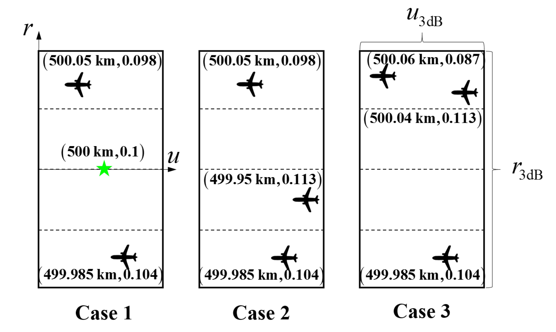
In the second example, three cases of unresolved targets are set as shown in Figure 6. There are two targets in Case 1 and three targets in Case 2 and Case 3. All the targets are located in the same conventional resolution cell whose center is . Targets of Case 1 and Case 2 are all separated in different subcells, but two targets of Case 3 are in the same one. In this example, SNR is defined as .
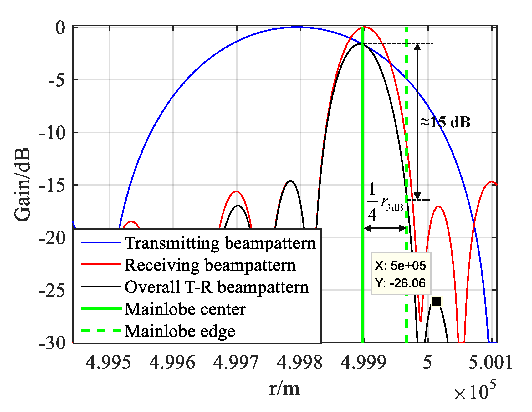
Figure 7 shows the overall T-R beampattern under scanning weights and . The overall T-R beampattern is indeed a spatial filter, which can suppress the target outside of mainlobe over . The sidelobe in the unresolved region is about , much lower than without intra-pulse beam scanning. The powers reflected by the targets out of receive mainlobe are much lower. It means we can use (18) to localize each unresolved target with little sidelobe interference from others.
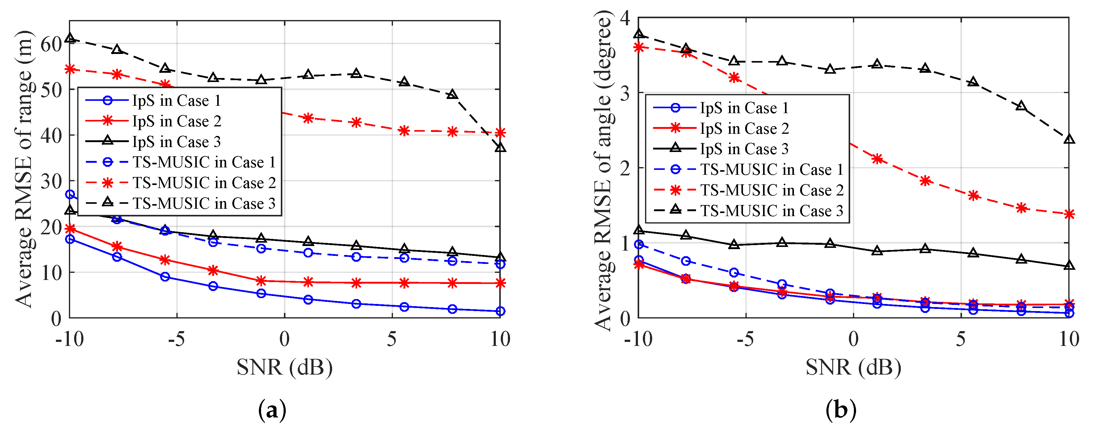
We examine the performance of intra-pulse beam scanning (IpS) and transmitting subaperture MUSIC (TS-MUSIC) [21] for comparison. Average root mean square error (RMSE) results of 100 Monte Carlo simulations are shown in Figure 8. The results demonstrate that the performance of IsP is much better than TS-MUSIC since there is only one snapshot available. The spatial smoothing of TS-MUSIC leads to the loss of array aperture which is a disadvantage on the localization of unresolved targets. Note that the performance of TS-MUSIC gets worse rapidly in the cases of three targets, but IsP not. It means IsP is a robust approach of unresolved targets localization. However, the estimate error of IsP increases in Case 3 because two targets are located in the same subcell.
6. Conclusions
In this paper, a novel transmit–receive system of FDA radar is proposed for multitarget localization. Considering both transmitting and receiving, the configurations of SB-FDA and FB-FDA are chosen as transmitter and receiver to obtain the range-angle-decoupled beampatterns. In such a system framework, the receive beamwidth is only a quarter of transmit. Then, two localization methods are proposed for two typical multitarget scenarios. By frequency increment selection and intra-pulse beam scanning, multitarget localization can be achieved with a few pulses. Simulation results demonstrate that the beampatterns can be steered to focus on one target only besides being staggered with others via frequency increment selection. Furthermore, a good localization performance can be achieved for unresolved targets by intra-pulse beam scanning. However, the localization error will increase greatly if multiple targets are located in the same subcell.
Author Contributions
S.L.W., Z.-h.X. participated in the design of this study, and they all performed the results analysis and manuscript preparation. X.L. and W.D. conceived and designed the simulations; G.W. also wrote the paper. All authors read and approved the final manuscript.
Funding
This work was supported in part by the National Nature Science Foundation of China of Grant NO. 61471372 and the Foundation of National Key Laboratory of Antennas and Microwave Technology NO. 61424020301162402005.
Acknowledgments
This work is supported by the National Natural Science Foundation of China (Grant No. 61471372) and the Foundation of National Key Laboratory of Antennas and Microwave Technology (Grant No. 61424020301162402005).
Conflicts of Interest
The authors declare no conflict of interest.
References
- Dorey, J.; Blanchard, Y.; Christophe, F. The RIAS project, a new approach to air surveillance radar. Radiant J. Dutch Meteor Soc. 1984, 20, 21–24. [Google Scholar]
- Wang, W.Q.; So, H.C.; Farina, A. An Overview on Time/Frequency Modulated Array Processing. IEEE J. Sel. Top. Signal Process. 2017, 11, 228–246. [Google Scholar] [CrossRef]
- Xu, J.; Zhu, S.; Liao, G.; Zhang, Y. An Overview of Frequency Diverse Array Radar Technology. J. Radars 2018, 7, 167–182. [Google Scholar]
- Wang, W.Q. Subarray-based frequency diverse array radar for target range-angle estimation. IEEE Trans. Aerosp. Electron. Syst. 2014, 50, 3057–3067. [Google Scholar] [CrossRef]
- Wang, W.Q.; Shao, H. Range-Angle Localization of Targets by A Double-Pulse Frequency Diverse Array Radar. IEEE J. Sel. Top. Signal Process. 2014, 8, 106–114. [Google Scholar] [CrossRef]
- Khan, W.; Qureshi, I.M.; Basit, A.; Zubair, M. A Double Pulse MIMO Frequency Diverse Array Radar for Improved Range-Angle Localization of Target. Wirel. Pers. Commun. 2015, 82, 1–15. [Google Scholar] [CrossRef]
- Huang, L.; Li, X.; Gong, P.C.; He, Z. Frequency diverse array radar for target range-angle estimation. COMPL Int. J. Comput. Math. Electr. 2016, 35, 1257–1270. [Google Scholar] [CrossRef]
- Blair, W.D.; Brandt-Pearce, M. Monopulse DOA estimation of two unresolved Rayleigh targets. IEEE Trans. Aerosp. Electron. Syst. 2002, 37, 452–469. [Google Scholar] [CrossRef]
- Wang, W.Q.; So, H.C.; Shao, H. Nonuniform Frequency Diverse Array for Range-Angle Imaging of Targets. IEEE Sens. J. 2014, 14, 2469–2476. [Google Scholar] [CrossRef]
- Khan, W.; Qureshi, I.M.; Basit, A.; Khan, W. Range-Bins-Based MIMO Frequency Diverse Array Radar With Logarithmic Frequency Offset. IEEE Antennas Wirel. Propag. Lett. 2016, 15, 885–888. [Google Scholar] [CrossRef]
- Shao, H.; Dai, J.; Xiong, J.; Chen, H.; Wang, W.Q. Dot-Shaped Range-Angle Beampattern Synthesis for Frequency Diverse Array. IEEE Antennas Wirel. Propag. Lett. 2016, 15, 1703–1706. [Google Scholar] [CrossRef]
- Gao, K.; Wang, W.Q.; Chen, H.; Cai, J. Transmit Beamspace Design for Multi-Carrier Frequency Diverse Array Sensor. IEEE Sens. J. 2016, 16, 5709–5714. [Google Scholar] [CrossRef]
- Basit, A.; Qureshi, I.; Khan, W.; Rehman, S.; Khan, M.M. Beam Pattern Synthesis for an FDA Radar with Hamming Window based Non-uniform Frequency Offset. IEEE Antennas Wirel. Propag. Lett. 2017, 16, 2283–2286. [Google Scholar] [CrossRef]
- Wang, Z.; Wang, W.Q.; Shao, H. Range-azimuth decouple beamforming for frequency diverse array with Costas-sequence modulated frequency offsets. Eurasip J. Adv. Signal Process. 2016, 2016, 124. [Google Scholar] [CrossRef]
- Xiong, J.; Wang, W.Q.; Shao, H.; Chen, H. Frequency Diverse Array Transmit Beampattern Optimization With Genetic Algorithm. IEEE Antennas Wirel. Propag. Lett. 2017, 16, 469–472. [Google Scholar] [CrossRef]
- Chen, H.; Shao, H.Z.; Wang, W.Q. Joint Sparsity-Based Range-Angle-Dependent Beampattern Synthesis for Frequency Diverse Array. IEEE Access 2017, 5, 15152–15161. [Google Scholar] [CrossRef]
- Li, Q.; Huang, L.; So, H.C.; Xue, H.; Zhang, P. Beampattern Synthesis for Frequency Diverse Array via Reweighted ℓ1 Iterative Phase Compensation. IEEE Trans. Aerosp. Electron. Syst. 2018, 54, 467–475. [Google Scholar] [CrossRef]
- Xu, Y.; Shi, X.; Xu, J.; Huang, L.; Li, W. Range-angle-decoupled beampattern synthesis with subarray-based frequency diverse array. Dig. Signal Process. 2017, 64, 49–59. [Google Scholar] [CrossRef]
- Jones, A.M.; Rigling, B.D. Planar frequency diverse array receiver architecture. In Proceeding of the Radar Conference, Atlanta, GA, USA, 7–11 May 2012; pp. 145–150. [Google Scholar]
- Wang, S.L.; Xu, Z.H.; Liu, X.; Dong, W.; Wang, G. Subarray-Based Frequency Diverse Array for Target Range-Angle Localization With Monopulse Processing. IEEE Sens. J. 2018, 18, 5937–5947. [Google Scholar] [CrossRef]
- Wang, W.Q.; So, H.C. Transmit Subaperturing for Range and Angle Estimation in Frequency Diverse Array Radar. IEEE Trans. Signal Process. 2014, 62, 2000–2011. [Google Scholar] [CrossRef]
- Xu, J.; Liao, G.; Zhu, S.; Huang, L.; So, H.C. Joint Range and Angle Estimation Using MIMO Radar with Frequency Diverse Array. IEEE Trans. Signal Process. 2015, 63, 3396–3410. [Google Scholar] [CrossRef]
- Xu, J.; Liao, G.; Zhang, Y.; Ji, H.; Huang, L. An Adaptive Range-Angle-Doppler Processing Approach for FDA-MIMO Radar Using Three-Dimensional Localization. IEEE J. Sel. Top. Signal Process. 2017, 11, 309–320. [Google Scholar] [CrossRef]
- Qin, S.; Zhang, Y.D.; Amin, M.G.; Gini, F. Frequency Diverse Coprime Arrays with Coprime Frequency Offsets for Multitarget Localization. IEEE J. Sel. Top. Signal Process. 2017, 11, 321–335. [Google Scholar] [CrossRef]
- Eaves, J.L.; Reedy, E.K. Principles of Modern Radar; SciTech Publication: Chennai, India, 2010; pp. 40–43. [Google Scholar]
- Nickel, U. Superresolution using an active antenna array. In Proceedings of the IEE International Conference Radar, London, UK, 18–20 October 1982. [Google Scholar]
- Bertsekas, D.P. Nonlinear Programming. J. Oper. Res. Soc. 1997, 48, 334. [Google Scholar] [CrossRef]
- Blair, W.D.; Brandt-Pearce, M. Unresolved Rayleigh target detection using monopulse measurements. IEEE Trans. Aerosp. Electron. Syst. 1998, 34, 543–552. [Google Scholar] [CrossRef]
- Zhang, X.; Willett, P.K.; Bar-Shalom, Y. Monopulse Radar detection and localization of multiple unresolved targets via joint bin Processing. IEEE Trans. Signal Process. 2005, 53, 1225–1236. [Google Scholar] [CrossRef]
- Glass, J.D.; Blair, W.D. Detection of rayleigh targets using adjacent matched filter samples. IEEE Trans. Aerosp. Electron. Syst. 2015, 51, 1927–1941. [Google Scholar] [CrossRef]
- Kliger, I.E.; Olenbergermber, C.F. Multiple Target Effects on Monopulse Signal Processing. IEEE Trans. Aerosp. Electron. Syst. 1975, 11, 795–804. [Google Scholar] [CrossRef]
- Taylor, J.D. Advanced Ultrawideband Radar: Signals, Targets, and Applications; CRC Press: Boca Raton, FL, USA, 2016. [Google Scholar]
- Babur, G.; Aubry, P.; Chevalier, F.L. Simple transmit diversity technique for phased array radar. IET Radar Sonar Navig. 2016, 10, 1046–1056. [Google Scholar] [CrossRef]
- Stoica, P.; Nehorai, A. Performance study of conditional and unconditional direction-of-arrival estimation. IEEE Trans. Acoust. Speech Signal Process. 1990, 38, 1783–1795. [Google Scholar] [CrossRef]
- Xiong, J.; Wang, W.Q.; Gao, K. FDA-MIMO Radar Range-Angle Estimation: CRLB, MSE and Resolution Analysis. IEEE Trans. Aerosp. Electron. Syst. 2018, 54, 284–294. [Google Scholar] [CrossRef]
Figure 1.
Illustration of transmit and receive antenna array configuration.

Figure 2.
Intra-pulse beam scanning of transmit beampattern for unresolved targets.

Figure 3.
(a) Transmit, (b) receive and (c) overall T-R beampatterns with selected frequency increment.
Figure 3.
(a) Transmit, (b) receive and (c) overall T-R beampatterns with selected frequency increment.

Figure 4.
Slices of transmit and receive beampattern in (a) range and (b) angle.

Figure 5.
Output SINR vertus SNR in different interference cases.

Figure 6.
Three cases of multiple unresolved targets.

Figure 7.
The overall T-R beampattern with intra-pulse beam scanning.

Figure 8.
RMSE of unresolved targets localization in (a) range and (b) angle.


Table 1.
Locations of sparse targets.
| Location | Location | ||
|---|---|---|---|
| Target 1 | Target 2 | ||
| Target 3 | Target 4 | ||
| Target 5 | Target 6 |
Table 2.
Three cases of interference.
| Case | Interference 1 | Interference 2 | Interference 3 |
|---|---|---|---|
| 1 | |||
| 2 | |||
| 3 |
© 2018 by the authors. Licensee MDPI, Basel, Switzerland. This article is an open access article distributed under the terms and conditions of the Creative Commons Attribution (CC BY) license (http://creativecommons.org/licenses/by/4.0/).
Share and Cite
MDPI and ACS Style
Luo Wang, S.; Xu, Z.-h.; Liu, X.; Dong, W.; Wang, G. A Novel Transmit–Receive System of Frequency Diverse Array Radar for Multitarget Localization. Electronics 2018, 7, 408. https://doi.org/10.3390/electronics7120408
AMA Style
Luo Wang S, Xu Z-h, Liu X, Dong W, Wang G. A Novel Transmit–Receive System of Frequency Diverse Array Radar for Multitarget Localization. Electronics. 2018; 7(12):408. https://doi.org/10.3390/electronics7120408
Chicago/Turabian StyleLuo Wang, Shengbin, Zhen-hai Xu, Xinghua Liu, Wei Dong, and Guoyu Wang. 2018. "A Novel Transmit–Receive System of Frequency Diverse Array Radar for Multitarget Localization" Electronics 7, no. 12: 408. https://doi.org/10.3390/electronics7120408
Note that from the first issue of 2016, this journal uses article numbers instead of page numbers. See further details here.