Article

Operating Wireless Sensor Nodes without Energy Storage: Experimental Results with Transient Computing

1
Thomas Johann Seebeck Department of Electronic, Tallinn University of Technology, Tallinn 12616, Estonia
2
University of Tartu, Narva College, Narva 20307, Estonia
*
Authors to whom correspondence should be addressed.
Electronics 2016, 5(4), 89; https://doi.org/10.3390/electronics5040089
Submission received: 22 November 2016 / Revised: 2 December 2016 / Accepted: 6 December 2016 / Published: 9 December 2016

Abstract

:
Energy harvesting is increasingly used for powering wireless sensor network nodes. Recently, it has been suggested to combine it with the concept of transient computing whereby the wireless sensor nodes operate without energy storage capabilities. This new combined approach brings benefits, for instance ultra-low power nodes and reduced maintenance, but also raises new challenges, foremost dealing with nodes that may be left without power for various time periods. Although transient computing has been demonstrated on microcontrollers, reports on experiments with wireless sensor nodes are still scarce in the literature. In this paper, we describe our experiments with solar, thermal, and RF energy harvesting sources that are used to power sensor nodes (including wireless ones) without energy storage, but with transient computing capabilities. The results show that the selected solar and thermal energy sources can operate both the wired and wireless nodes without energy storage, whereas in our specific implementation, the developed RF energy source can only be used for the selected nodes without wireless connectivity.

Graphical Abstract

1. Introduction

Advances in semiconductor technology has given birth to low-power, miniaturized computing units (microcontrollers, DSPs, (nano)-FPGAs), and radio modules. Such circuits are commonly used for implementing the nodes in wireless sensor networks (WSN) and, more generally, in the internet of things (IoT). On the other hand, and although new battery technologies (e.g., hydrogen fuel cells) are being developed and promise new performance levels, those available today are not always sufficient when it comes to filling the gap between the physical size, capacity, and energy requirements of the computing and communication modules of the nodes.
Furthermore, for some applications, it is sometimes not possible to include a battery or super-capacitor in the nodes due to stringent physical constraints or for maintenance reasons (for example, it may be impossible to access a node integrated in a physical structure and replace its energy storage unit if the battery fails or once its maximum number of charge/discharge cycles have been reached, in the case of e.g., intensive and/or very-long term applications) [1].
Thus, many research efforts strive at designing (A) architectural solutions that effectively reduce energy consumption in the processing and communication modules, and (B) energy harvesting (EH) solutions that can complement, or even replace, the energy storage units of the nodes for, e.g., autonomous systems, leading to the concept of transient computing (TC) discussed later on.
In the context of WSN nodes, the idea of using EH emerged in the late 1990s [2] and refers to the various techniques that allow collecting energy from the environment (solar, thermal, radio frequency (RF), etc.) and use it to recharge and/or complement energy storage units, such as rechargeable batteries or super-capacitors, especially in the context of fully-autonomous WSN nodes and/or for prolonging the lifespan of battery-powered WSN nodes. EH, aided by energy prediction or estimation, has led to a service-oriented infrastructure supporting a broad range of applications such as IoT and cyber-physical systems by optimizing the energy consumption and balancing the traffic load to increase the nodes’ lifetime.
Nevertheless, EH remains challenging in many cases (e.g., for wearable sensors) due to strict form factor constraints and usability concerns [3,4].
Examples of EH used in wearable WSNs include the research proposed in [1] where the authors conducted real-world scenario experiments and achieved 550 μW for an indoor photovoltaic source and 98–250 μW for a thermal source with 3° and 5° temperature gradients, respectively. Several works have been proposed to minimize the RF energy requirements of the devices with different techniques, such as at the physical layer [4,5], MAC, routing algorithms, and duty cycle [6,7,8,9]. In [10], the authors used solar and wind energy harvesters and interfaced them with an ultralow power WSN hardware infrastructure that is suitable for long-term wireless structural health monitoring (WSHM).
RF-EH is an emerging alternative among the numerous energy harvesting techniques. Indeed, many RF transmitters (TV towers, mobile base stations, wireless access points, and even dedicated RF transmitters) have been deployed in the past decades; RF energy can, thus, be considered as easily available in many places [11], especially in indoor environments [12]. RF-EH has found applications in wireless charging, wireless body area networks, surveillance, and cognitive radio networks [13,14] with quality of service (QoS) constraints. Harvesting such energy is typically achieved by means of a so-called rectenna, connected to the WSN nodes, that converts a share of the available energy of the RF signal into electrical energy. Such rectennas are typically composed of an antenna and matched voltage multiplier/rectifying circuitry tuned to the radio frequency of interest; such a setup converts the RF signal to a DC voltage. In particular, dedicated indoor RF sources possibly provides higher AC voltages and, thus, DC voltages, because of typically short distances between the energy source and the nodes, e.g., 1.25 V @ 0.5 m [11]. Furthermore, when it comes to large-scale wireless networks, simulation results [15] indicate that RF-EH can increase the lifetime of a network by up to 70% while maintaining adequate quality of service. Simulation results presented in [16] suggest that RF-EH can increase the lifetime of randomly-deployed dense cooperative WSNs up to 69%.
In [17] the authors focused on a solar energy harvester and energy management, in combination with a new energy forecast model for WSNs. In [18], the authors proposed a hybrid energy harvesting concept based on wind, solar, and chemical energy, which can be used for both simultaneous and individual harvesting processes.
As illustrated above, a large body of research related to EH for WSNs and the IoT has been published in the literature; the interested reader can refer to, e.g., [19] for a recent overview.
That being said, there is still room for research in this field. For example, it has recently been suggested in [3] to combine the concepts of EH and TC. The overall idea stems from the fact that harvested energy is typically fluctuating and intermittent, possibly leaving the WSN nodes without power (even if they include a battery or super-capacitor since these can possibly reach a discharged state). Another argument behind TC is to enable the design and implementation of WSN nodes that operate without an energy storage unit (for e.g., size or maintenance issues, as mentioned earlier).
Such WSN nodes operating with energy storage, but complemented with TC, are suitable for, e.g., applications that do not require permanent monitoring, or that are tolerant to delays (e.g., storing data locally and transmitting it when energy is again available), or that are tolerant to missing data (such missing data can sometimes be compensated for by means of spatial or temporal correlation techniques).
A critical issue in TC is stopping (ideally pausing) and restarting (ideally resuming) computations depending on the available power. For this, several methods, such as checkpointing [20,21] and dynamic power management [22], have been recently proposed. They all rely on the use of microcontrollers that feature non-volatile memory, i.e., flash or more recently ferroelectric RAM (FRAM), to enable saving and restoring the state and data of the node.
One of the first research effort related to TC is the Mementos approach, proposed by Ransford et al. [20]. It turns general computing programs into interruptible versions that are ‘protected’ from frequent power cuts by means of a checkpointing mechanism that saves and restores the context data and program into flash memory on a periodic basis. Although this mechanism adds an overhead in terms of execution time, it enables suspending the execution when the voltage reaches a given threshold and resuming when the voltage rises sufficiently again. In effect, this type of approach enables spreading computation over time as a function of the available energy.
As a follow-up to the above, DINO (“Death Is Not an Option”) [23] adds support for dealing with the inconsistency between volatile and non-volatile data that may occur due to frequent interrupts. Another novelty in DINO is the use of a microcontroller based on FRAM instead of Flash memory. The reported execution-time overhead for DINO is between 1.8× and 2.7×.
Further improvements to TC have been proposed in Hibernus [21]. The key idea here is to replace the periodic checkpointing by an ad-hoc technique, whereby the microcontroller enters the save mode only when the power supply voltage falls to a given threshold (detected by means of a comparator). Hibernus significantly reduces the number of checkpoints and, thus, reduces the execution time and energy overheads by 76%–100% and 49%–79%, respectively, as compared to Mementos.
QuickRecall [24] goes one step further by using the FRAM in a unified mode (i.e., containing the instructions, data, and saves); thus, the RAM is not used, which can reduce execution time and energy consumption since there are no data transfers between the FRAM and the RAM.
Recently, Balsamo et al. [22] have developed a TC method that adapts the power consumption of energy-storage-less devices dynamically by means of dynamic frequency scaling (DFS), which allows handling energy fluctuations in a finer manner. In addition to a threshold for detecting power cuts, two extra thresholds are used to help decide if the voltage and frequency of the FRAM-based microcontroller should be decreased or increased. Tests conducted on Fast Fourier Transform (FFT), Cycling Redundancy check (CRC), and Rivest, Shamir, and Adleman (RSA) algorithms together with solar and micro-turbine energy harvesters show that it is not only possible to adjust the performance of the microcontroller but also to effectively reduce the number of save and restore phases since the microcontroller is allowed to run in a lower performance mode when the available power is reduced.
Whereas transient computing has been demonstrated on microcontrollers (mostly without wireless connectivity features), the literature still lacks reports on experiments with wireless-enabled sensor nodes. The purpose of this paper is to share findings and experimental results obtained when three EH sources (solar, thermal, and RF) are used to power both wired and wireless sensor nodes without energy storage, and evaluate the practical feasibility of TC for WSNs.
The main contributions presented in this paper are:
(A)
The practical implementation of three EH sources combined with a TC method on FRAM wireless sensor nodes, and
(B)
The assessment of the practical feasibility of such combinations.
In particular, it is shown that for the selected EH sources and nodes, the solar and thermal energy sources can power both non-wireless and wireless sensor nodes without energy storage, whereas in our specific implementation, the developed RF energy source can only be used for the selected nodes without wireless connectivity.

2. Materials and Methods

2.1. Energy Modeling

Before evaluating the practical feasibility of EH combined with TC, we briefly review the fundamentals of the three selected EH sources and related analytical models. These models are used to obtain baseline references against which the actual EH sources can be compared (including both indoor and outdoor environments for the solar energy source).

2.1.1. Solar Energy

Visible light can be converted into electrical energy via solar panels that are typically constructed from crystalline silicon cells (i.e., multicrystalline and monocrystalline silicon). Outdoor solar harvesting is a highly explored area and provides a higher value of energy [1]. However, ambient (mostly indoor) solar energy is not exploited as much since it generally provides less energy [25]. In [26], a formulation of the output power of a solar panel, PPV (VPV), is expressed as per Equation (1):
PPV (VPV) = VPV IPV = VPV ILVPV Io [exp (VPV/ns Vt) −1] ≈ VPV Isc − VPV Io [exp (VPV·q/ns·k·Tc)]
where VPV is the output voltage, IPV is the output current, IL is the light-generated current, Io is the dark/reverse saturation current of the p-n diodes, ns is the number of series solar cells, Vt is the junction terminal thermal voltage, q is the charge of the electron, k is Boltzmann constant, and Tc is the ambient temperature.

2.1.2. Thermal Energy

Thermoelectric generators (TEGs) exploit the Seebeck effect to produce electrical energy. TEGs are typically constructed from n-type and p-type semiconductors that are connected in series, which are combined with thermal ceramics in parallel. By connecting a load of resistance RL to the TEG, an electric current ITEG flows in accordance to the temperature difference. In [26], a model is proposed for a TEG energy harvester. The corresponding model equation is showed in Equation (2):
P TEG ( V TEG ) = V TEG × I TEG = ( V TEG × n × α × ( T H T C ) V TEG 2 ) R s ,   TEG
where n is the number of thermocouples, α is the Seebeck’s coefficient, Rs, TEG is the internal resistance, and ∆T is the temperature difference (TH–TC, where TH is the temperature of the hot side and TC is temperature of cold side).

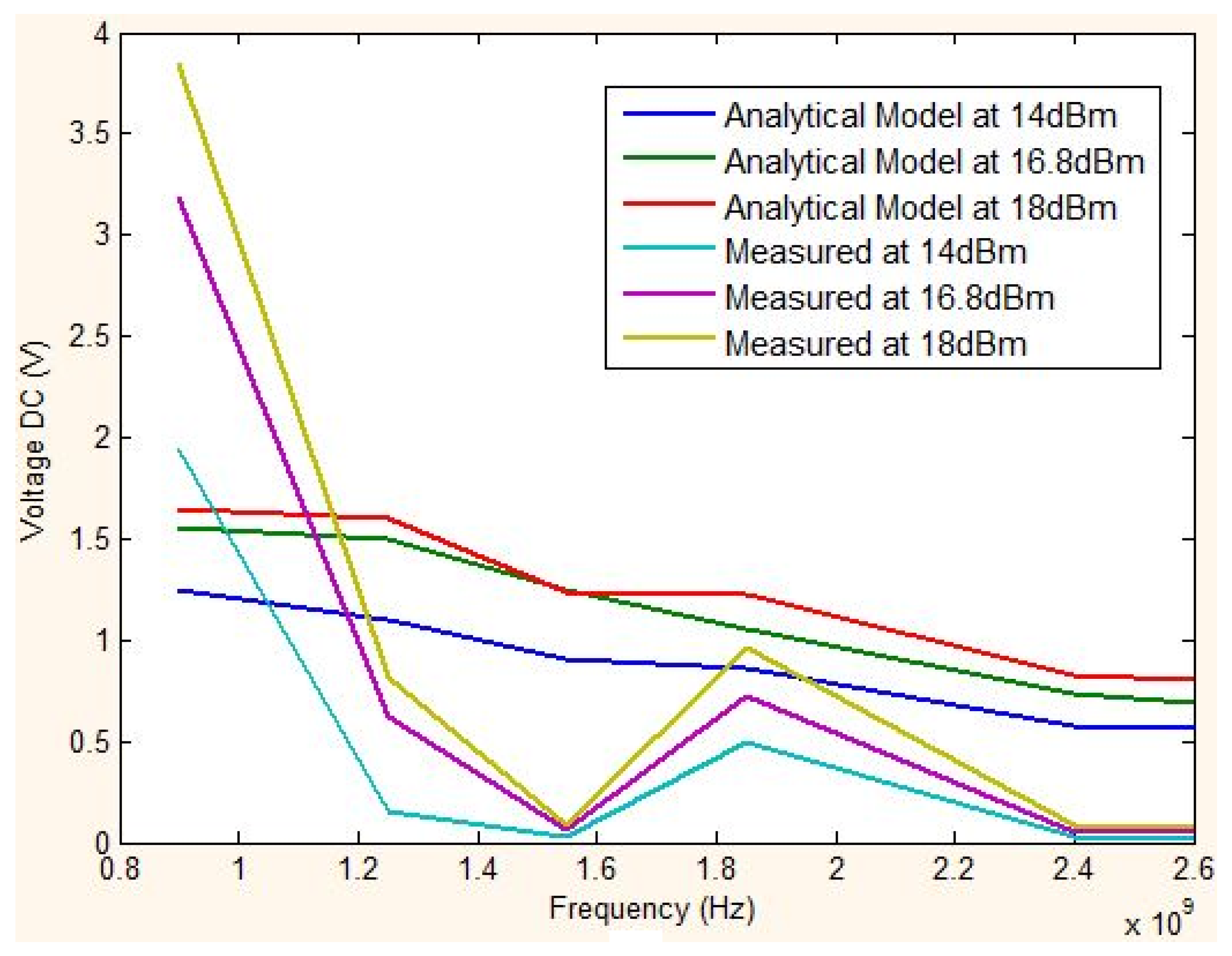
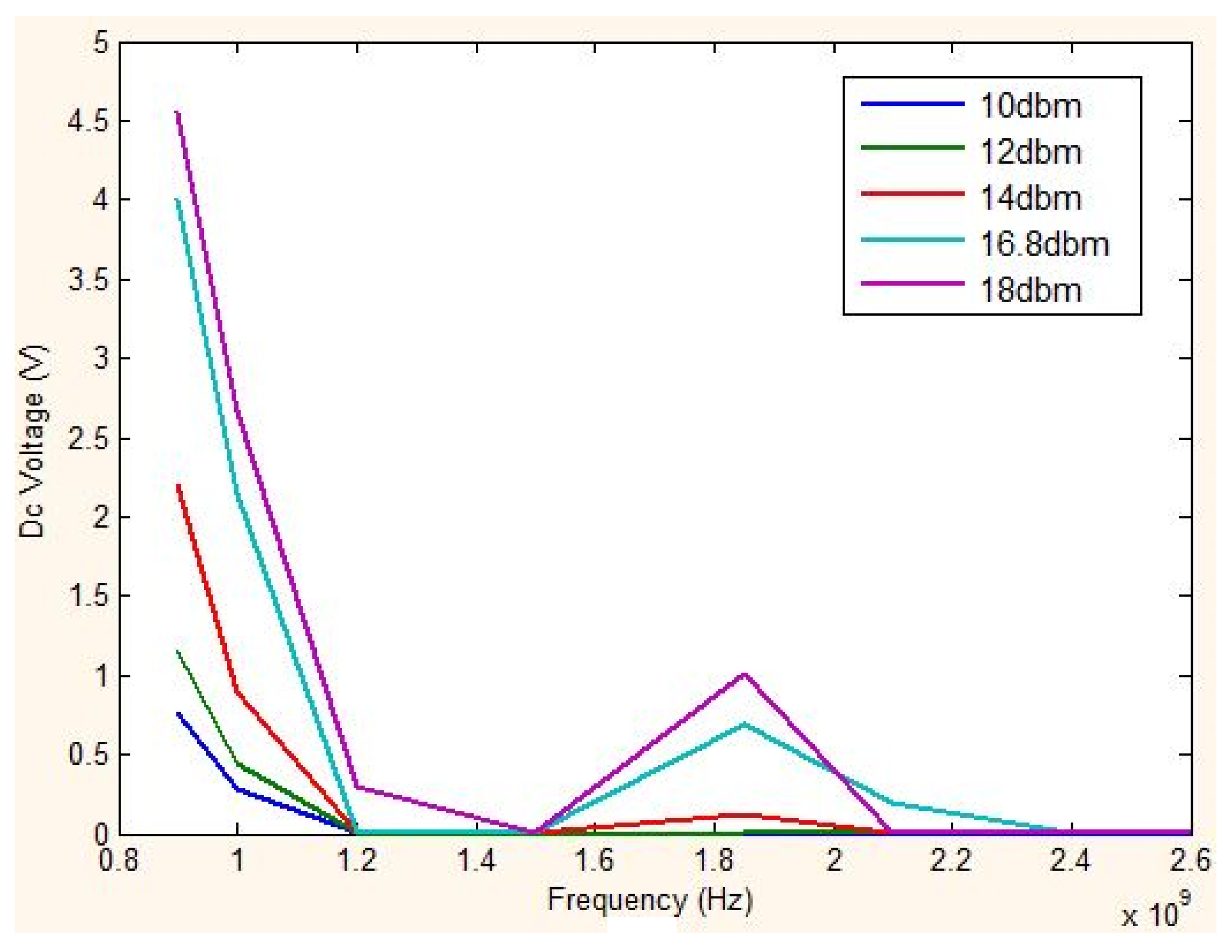
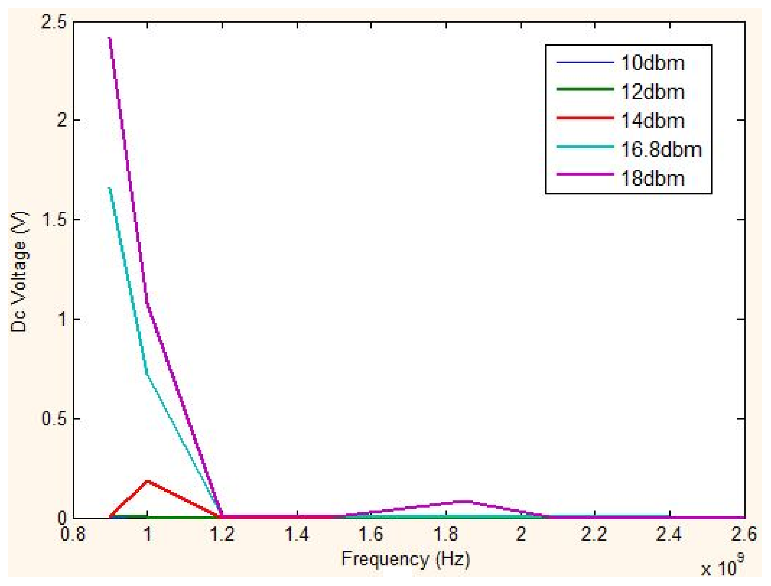
2.1.3. Radio-Frequency Energy

RF-EH devices are typically composed of an antenna matched to either a single or multiple frequency bands, combined with an impedance-matching circuit tuned to the targeted frequencies, followed by a voltage amplitude multiplier, e.g., as in the diode based, multi-stage voltage multiplier proposed in [11]. In addition to the quality of the matching circuit, an important limiting factor in RF-EH is the distance between the emitting radio source and the RF-EH circuit. In [11], an analytical model of an RF to DC voltage converter is proposed and expressed by Equations (3) and (4):
V = 2 [Gant λ/4π d (2Re [Zrec].Prf (1+Qrf2)) ½VF]
where V is the output voltage of the RF-EH circuit which performs the RF to DC conversion, Gant is the antenna gain, d is the distance, Re (Zrec) is the reactance, Prf is the maximum available power, Qrf is the quality factor, and VF the low forward voltage.
V out = n V 0 n R 0 + R L = V 0 R 0 R L + 1 n
where V0 (i.e., V in Equation (3)) is the input of the voltage multiplier, R0 is the internal resistance, RL is the load resistance, n is the number of stages, and Vout is the output voltage.
The above sections briefly reviewed the three EH sources used in this work. As mentioned earlier, various approaches combining TC and EH have been proposed in the literature. However, such approaches have not been widely experimented in practice, especially when actual radio modules are included; what follows describes our experimental setup for conducting such experiments; our results are then presented in Section 3.

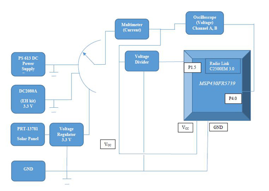
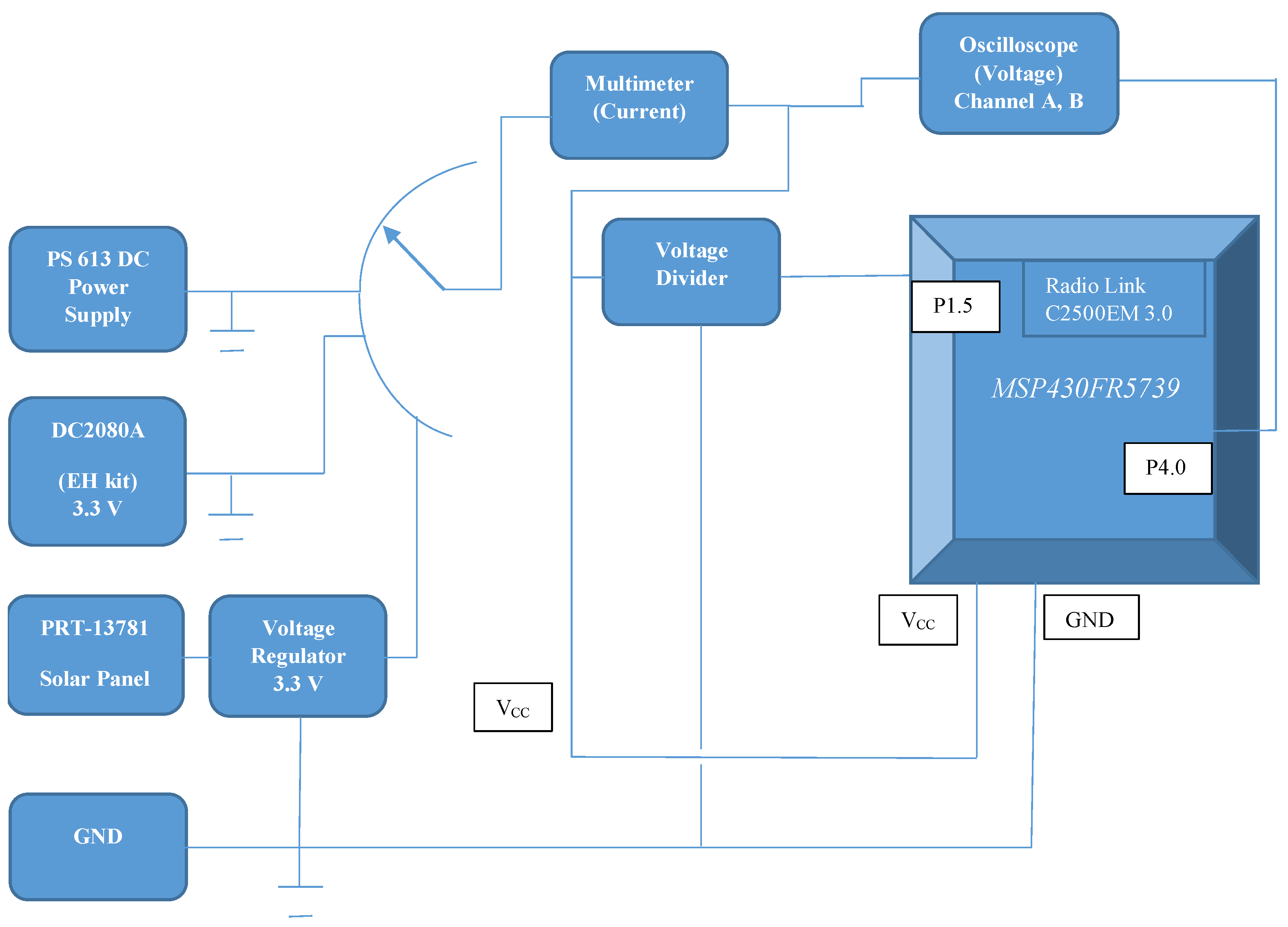
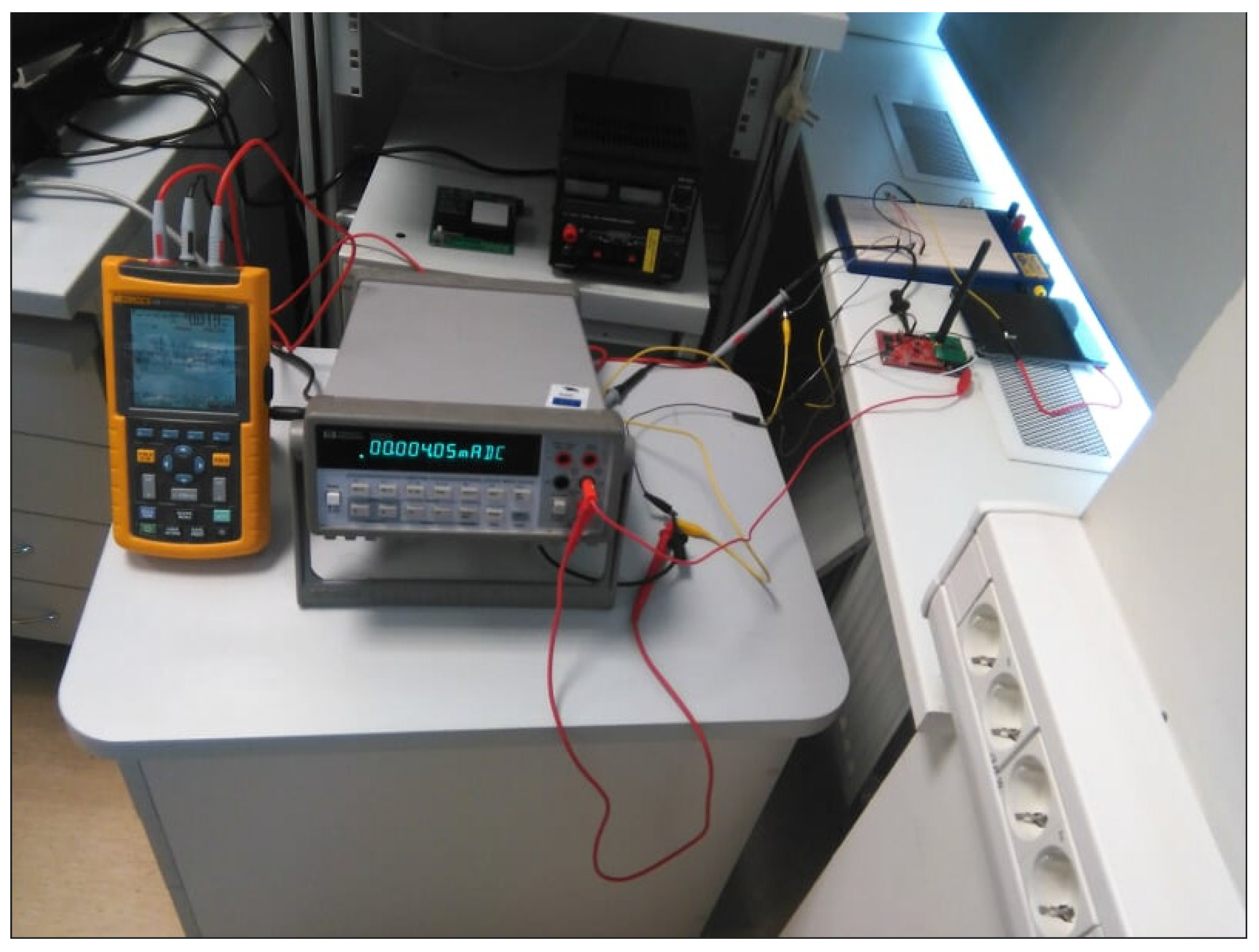
2.2. Experimental Setup

The experimental setup consists of the hardware listed below.
  • One MSP-EXP430G2 Launchpad kit (used as a temperature sensor node without wireless connectivity);
  • Two EZ430-RF2500 kits (used as temperature sensor nodes with wireless connectivity);
  • Two MSP-EXP430FR5739 kits with CC2500 evaluation module kit (used as sensor nodes with wireless connectivity and non-volatile FRAM memory);
  • One Linear Technology DC2080A energy harvesting multi source demo board including solar (Panasonic AM-5412) and TEG (CUI INC CP85438) energy sources, as well as an input for our self-developed RF-EH source;
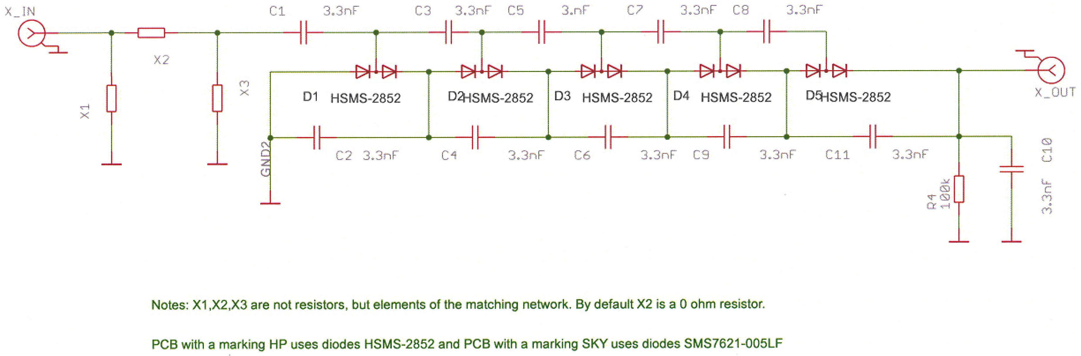
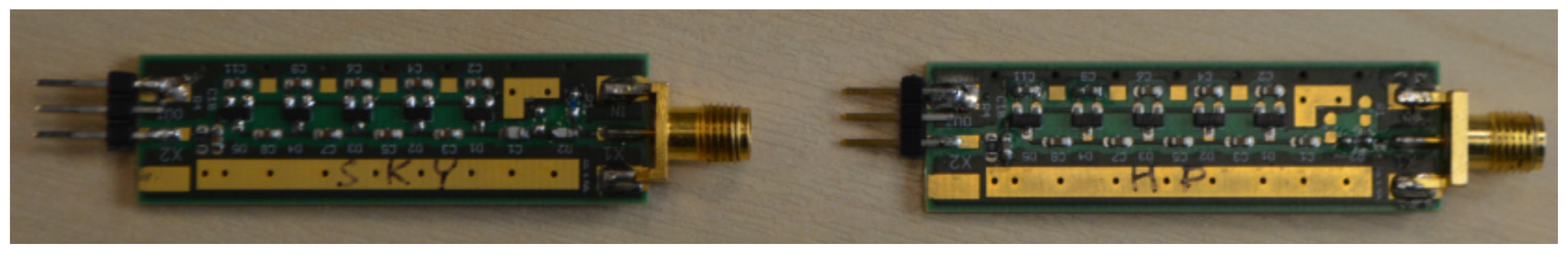
  • One self-developed RF-EH board (900 MHz matching network and five-stage voltage multiplier architecture);
  • Two Kent Electronics log periodic printed circuit board antennas (850 MHz to 6500 MHz);
  • One SMA 100 A Signal Generator—9 KHz to 6 GHz (used as an RF transmitter);
  • One Jameco PS 613 DC Power Supply;
  • One PRT-13781 solar panel (13.5 cm × 11.2 cm) and 3.3 V voltage regulator;
  • One Hewlett Packard 34401A Multimeter for measuring the current;
  • One Fluke 123 industrial scope meter for observing and measuring the voltages;
  • One TES 1335 light meter for measuring the illuminances.
The schematic of the self-developed RF-EH board is shown in Figure 1; the corresponding photograph is shown in Figure 2.
The code running on the MSP-EXP430FR5739 kits is the device-to-device example provided in the SimpliciTI RF protocol package from Texas Instrument. This package was ported to the MSP-EXP430RF5739 board by following the guidelines provided in [27]. The code has then been modified to implement a TC method. For this, “Compute through Power Loss Utility (CTPL)” from Texas Instrument was used [28]. It contains a set of functions for implementing the strategy, shown in Figure 3.
In a first set of experiments, the DC2080A board (with onboard solar panel, onboard TEG, and external RF energy harvester) was used. Each energy path (corresponding to the various sources) on the DC2080A board includes a voltage step-up converter and power manager. The three energy sources were first evaluated individually by configuring jumpers on the DC2080A board and then in a simple hybrid mode by means of OR-ring diodes. Several experiments were run with and without the small onboard capacitors (12 × 100 μF, configured via a jumper). These small onboard capacitors are not considered as ‘real’ energy storage (which would be implemented by e.g., supercapacitors or batteries). In a second set of experiments, the PRT-13781 solar panel and 3.3 V voltage regulator were used.
For the experiments with the MSP-EXP430FR5739 kits, a reference voltage (coming from the EH source through a voltage divider) is fed to the microcontroller pin 1.5, as can been seen in Figure 4. The proper operation of the CTPL utility has been verified by defining CTPL_BENCHMARK in the compiler and assembler predefined symbols, which enables toggling a pin to indicate that the CTPL function has been triggered (pin 4.0 in our case); this toggling pattern is shown in Figure 5. A photograph of the experimental setup is shown in Figure 6.

3. Experimental Results

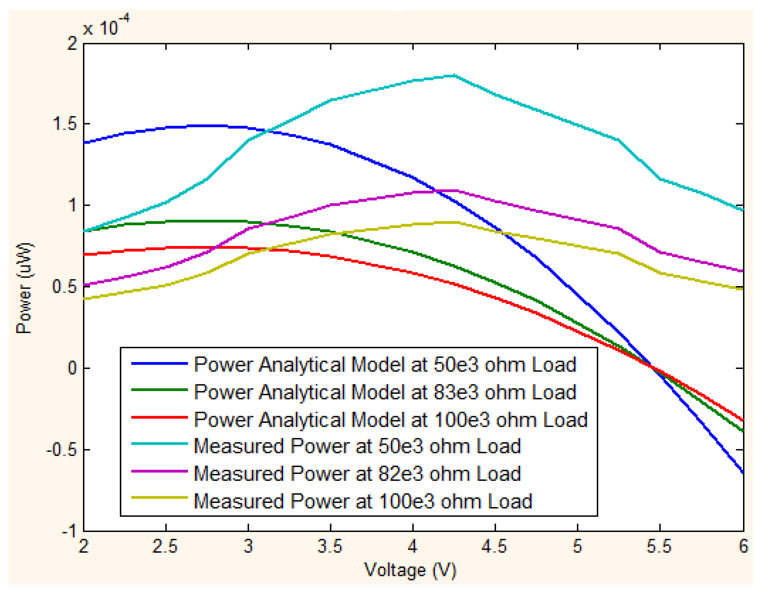
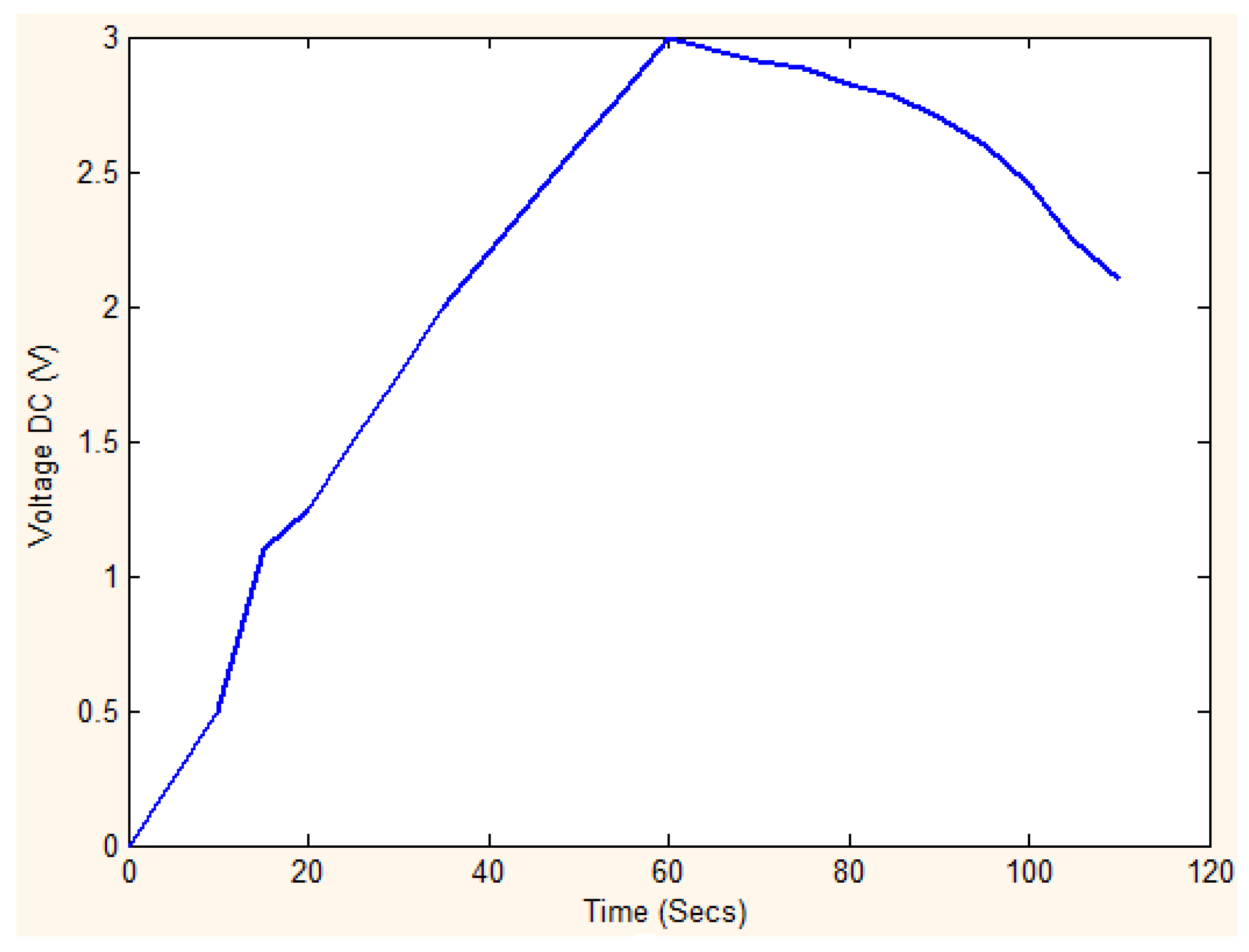
3.1. Powering the Nodes with RF-EH

We have first characterized the DC output voltage of the self-developed RF-EH (by means of the Kent Electronics log periodic printed circuit board antennas and SMA 100 A Signal Generator) and compared the measurements with the analytical models (described in Section 2.1.3). As shown in Figure 7, both simulated and measured output DC voltages peak at 900 MHz (the matching frequency) and, to a lesser degree, at 1.8 GHz. As can also be observed, although their orders of magnitude are similar, the simulated and measured curves do not fit perfectly. This can be explained by the fact that the selected analytical model is not sufficiently realistic since it does not take the conversion efficiency into account; in future work a model, such as the one proposed in [16], could be used instead.
We have then used the RF-EH circuit to power the MSP-EXP430G2 kit (configured as a wired temperature sensor). Figure 8 and Figure 9 show the output DC voltage for frequencies ranging from 900 MHz up to 2.6 GHz for five different RF levels (10, 12, 14, 16.8, and 18 dBm) with 2 cm and 5 cm distances between the transmitting (TX) and receiving (RX) antennas, respectively. As expected, the maximum output voltage is achieved at the matching frequency (900 MHz). It can also be seen that there is another smaller peak at 1.85 MHz for all input levels. The experimental results (first row in Table 1) show that the energy provided by the self-developed RF-EH board is sufficient to power the MSP-EXP430G2 kit configured as a wired temperature sensor with a distance of 5 cm and 18 dBm.
We have then used the RF-EH board to power the nodes that feature wireless connectivity (EZ430-RF2500 and MSP-EXP430FR5739 kits with CC2500 evaluation module kit). The experimental results show that the RF-EH board does not provide sufficient energy to operate the nodes featuring wireless connectivity, even whilst the small onboard capacitors are enabled. This is essentially due to the peak current that is required when the nodes boot and try to form or join the wireless network, which makes the voltage drop below the minimum operating voltage of the microcontrollers. However, the self-developed RF-EH is used for illustration purposes only and could be replaced by a more efficient one.

3.2. Powering the Nodes with the Onboard Solar Source

This experiment makes use of the onboard solar panel (3 cm × 5 cm) in a well-lighted office environment; it powers the three different types of nodes, one at a time. The experimental results (second row in Table 1) show that the solar energy source is able to boot and operate the three types of nodes (including with wireless connectivity), even whilst the small onboard capacitors are disabled.
Moreover, specific experiments have been conducted with the MSP-EXP430FR5739+CC2500 kits which were powered by alternative sources instead of those reported in Table 1. The two kits are programmed as a transmitter and a receiver. The results are presented in Table 2. The sources are (i) a fixed power supply and (ii) the onboard solar panel. Tests have been conducted both with and without wireless activity. Due to the low ambient illuminance, extra lamps had to be used to boot the nodes (measured at 9.98K LUX). As can be seen for the transmitter case, the current increases quite a lot when the radio in on, leading to a voltage drop. The same does not happen for the receiver.

3.3. Powering the Nodes with the PRT-13781 Solar Panel

As seen above, it is difficult to boot the MSP-EXP430FR5739+CC2500 kits with the onboard solar panel, mostly due to the peak current when booting. Thus, further experiments were also conducted with the larger PRT-13781 solar panel (13.5 × 11.2 cm); the results for the transmitter and receiver are presented in Table 3.

3.4. Powering the Nodes with the TEG Source

In this experiment, the analytical model (described in Section 2.1.2) and the measured output voltage of the onboard TEG EH are compared. The results shown in Figure 10 indicate that the orders of magnitude and overall trends are similar but not matching perfectly. This can be explained by the fact that some of the required parameters are not provided in the datasheet of the TEG module and had to be estimated.
Furthermore, the TEG EH source was used to power the three different nodes, one at a time. Keeping the palm of the hand on the TEG module gradually increased the temperature and, consequently, the output voltage, as shown in Figure 11 for the EZ430-RF2500 kit (used as a temperature sensor node with wireless connectivity). Due to this gradual start, it was necessary to use the small onboard capacitors to boot the nodes. The experimental results (third row in Table 1) show that whilst the TEG-EH does not provide as much energy as the onboard solar panel, it is also able to operate all three types of nodes (one at a time).

4. Concluding Remarks

Our practical experimental results show that EH combined with TC in WSN nodes is feasible. However, a number of conditions have to be met to makes this possible.
One of them is to implement a mechanism that allows pausing and resuming computations on the nodes depending on the available power. The results show that for simple applications, such as the one used in our experiments, a lightweight method like CTPL combined with a FRAM-based microcontroller is sufficient.
Another condition is to have energy sources that are powerful enough to power the nodes. The experimental results show that it is possible to boot and operate WSN nodes solely on certain harvested energy sources (in our case: solar, thermal, or hybrid), but not on others (in our case: RF and an onboard solar panel in ambient conditions). The experimental results also confirmed that the peak currents can be problematic, not only for booting the nodes but also for resuming computations after a power cut. Although adding extra capacitors might alleviate the problem, this would somehow defeat the whole purpose of operating WSN nodes without energy storage units.
Generally speaking, the experimental results are positive, but also highlight the need for careful dimensioning of the EH sources and the save/restore method. For those applications that are more complex or more demanding, it would most likely be needed to use more sophisticated methods, such as the ones discussed in the introduction; this is a possible topic for future work.
Another topic that needs to be further investigated is the impact that TC has on the application that runs on the WSN nodes in terms of quality of services (QoS) and quality of experience (QoE), especially for a large number of nodes. For this, it would be best to begin with simulations to evaluate metrics, such as delay, latency, throughput, and jitter in a system where the nodes are on and off at different times. Despite the fact that, in general, such patterns are expected to degrade the QoS and QoE, it might be possible to apply some of the methods and techniques developed for delay-tolerant networking and disruption-tolerant networking (although the memory and bandwidth overheads would have to be minimized significantly).

Acknowledgments

This work has been supported in part by TUT baseline project B38 and IT Academy stipend program. This project has also received funding from the European Union’s Horizon 2020 research and innovation programme under grant agreement No 668995. This material reflects only the authors’ view and the EC Research Executive Agency is not responsible for any use that may be made of the information it contains. We are also very thankful to Dr. J. Ojarand, Mr. M. Reidla, Mr. M. Lavrov and Mr. M. Rist for their technical support throughout the experiments.

Author Contributions

F. Ahmed, T. Ahmed and Y. Le Moullec designed and performed the experiments and analyzed the results; P. Annus and Y. Muhammad provided hardware resources and helped analyze the results. All authors participated in the paper writing...

Conflicts of Interest

The authors declare no conflict of interest. The founding sponsors had no role in the design of the study; in the collection, analyses, or interpretation of data; in the writing of the manuscript, and in the decision to publish the results.

References

  1. Magno, M.; Brunelli, D.; Sigrist, L.; Andri, R.; Cavigelli, L.; Gomez, A.; Benini, L. InfiniTime: Multi-sensor wearable bracelet with human body harvesting. Sustain. Comput. Inform. Syst. 2016, 11, 38–49. [Google Scholar] [CrossRef]
  2. Chandrakasan, A.; Amirtharajah, R.; Goodman, J.; Konduri, G.; Kulik, J.; Rabiner, W.; Wang, A. Design Considerations for Distributed Microsensor Systems. In Proceedings of the IEEE 1999 Custom Integrated Circuits Conference, Cat. No.99CH36327, San Diego, CA, USA, 19 May 1999; pp. 279–286.
  3. Arreola, A.R.; Balsamo, D.; Das, A.K.; Weddell, A.S.; Brunelli, D.; Al-Hashimi, B.M.; Merrett, G.V. Approaches to Transient Computing for Energy Harvesting Systems: A Quantitative Evaluation. In Proceedings of the 3rd International Workshop on Energy Harvesting & Energy Neutral Sensing Systems—ENSsys ’15, Seoul, Korea, 1–4 November 2015; pp. 3–8.
  4. Jelicic, V.; Magno, M.; Brunelli, D.; Bilas, V.; Benini, L. Benefits of Wake-up Radio in Energy-Efficient Multimodal Surveillance Wireless Sensor Networks. Sens. J. 2016, 14, 3210–3220. [Google Scholar] [CrossRef]
  5. Jelicic, V.; Magno, M.; Brunelli, D.; Bilas, V.; Benini, L. Analytic Comparison of Wake-up Receivers for WSNs and Benefits over the Wake-on Radio Scheme. In Proceedings of the 7th ACM Workshop on Performance Monitoring and Measurement of Heterogeneous Wireless and Wired Networks, Paphos, AA, Cyprus, 21–25 October 2012; pp. 99–106.
  6. Magno, M.; Benini, L.; Gaggero, L.; la Torre Aro, J.P.; Popovici, E. A Versatile Biomedical Wireless Sensor Node with Novel Dry Surface Sensors and Interfaces. In Proceedings of the 5th IEEE International Workshop, Bari, Italy, 13–14 June 2013; pp. 217–222.
  7. Karlen, W.; Floreano, D. Adaptive Sleep-Wake Discrimination for Wearable Devices. Biomed. Eng. IEEE Trans. 2011, 58, 920–926. [Google Scholar] [CrossRef] [PubMed]
  8. Subendran, P.; Viswanath, S.K.; Yuen, C.; Veerappan, C.S. Adaptive Transmission for Self-Sustainable Energy Harvesting Wireless Sensor Network. In Proceedings of the Frontiers of Communications, Networks and Applications (ICFCNA 2014—Malaysia), Kampar, Malaysia, 3–5 November 2014.
  9. Wan, Z.G.; Tan, Y.K.; Yuen, C. Review on Energy Harvesting and Energy Management for Sustainable Wireless Sensor Networks. In Proceedings of the 2011 IEEE 13th International Conference on Communication Technology, Jinan, China, 25–28 September 2011; pp. 362–367.
  10. Magno, M.; Boyle, D.; Brunelli, D.; Flynn, B.O.; Popovici, E.; Member, S.; Benini, L. Hybrid Energy Supply. IEEE Trans. Ind. Electron. 2014, 61, 1871–1881. [Google Scholar] [CrossRef]
  11. Taris, T.; Vigneras, V.; Fadel, L. A 900 MHz RF Energy Harvesting Module. In Proceedings of the 10th IEEE International New Circuits and Systems Conference (NEWCAS 2012), Montreal, QC, Canada, 17–20 June 2012; pp. 445–448.
  12. Georgiou, O.; Mimis, K.; Halls, D.; Thompson, W.H.; Gibbins, D. How Many Wi-Fi APs Does it Take to Light a Lightbulb? IEEE Access 2016, 4, 3732–3746. [Google Scholar] [CrossRef]
  13. Lu, X.; Wang, P.; Niyato, D.; Kim, D.I.; Han, Z. Wireless Networks with RF Energy Harvesting: A Contemporary Survey. IEEE Commun. Surv. Tutorials 2014, 17, 757–789. [Google Scholar] [CrossRef]
  14. Mustufa, Y.S.A.; Barton, J.; Flynn, B.O.; Davies, R.; McCullagh, P.; Zheng, H. Design of a Smart Insole for Ambulatory Assessment of Gait. In Proceedings of the 12th International Conference on BSN, Cambridge, MA, USA, 9–12 June 2015; pp. 1–5.
  15. Mekikis, P.V.; Lalos, A.S.; Antonopoulos, A.; Alonso, L.; Verikoukis, C. Wireless energy harvesting in two-way network coded cooperative communications: A stochastic approach for large scale networks. IEEE Commun. Lett. 2014, 18, 1011–1014. [Google Scholar] [CrossRef]
  16. Mekikis, P.V.; Antonopoulos, A.; Kartsakli, E.; Lalos, A.S.; Alonso, L.; Verikoukis, C. Information Exchange in Randomly Deployed Dense WSNs with Wireless Energy Harvesting Capabilities. IEEE Trans. Wirel. Commun. 2016, 15, 3008–3018. [Google Scholar] [CrossRef]
  17. Zhang, P.; Tan, H.; Xiao, G.; Yi, Yu. Maximizing Lifetime in Clustered WSN s with Energy Harvesting Relay: Profiling and Modeling. In Proceedings of the 2015 IEEE Tenth International Conference on Intelligent Sensors, Sensor Networks and Information Processing (ISSNIP), Singapore, 7–9 April 2015; pp. 1–6.
  18. Wu, Y.; Zhong, X.; Wang, X.; Yang, Y.; Wang, Z.L. Hybrid Energy Cell for Simultaneously Harvesting Wind, Solar, and Chemical energies. Nano Res. 2014, 7, 1631–1639. [Google Scholar] [CrossRef]
  19. Shaikh, F.K.; Zeadally, S. Energy harvesting in wireless sensor networks: A comprehensive review. Renew. Sustain. Energy Rev. 2016, 55, 1041–1054. [Google Scholar]
  20. Ransford, B.; Sorber, J.; Fu, K. Mementos. Mementos: System Support for Long-Running Computation on RFID-Scale Devices. ACM SIGPLAN Not. 2011, 46, 159–170. [Google Scholar] [CrossRef]
  21. Balsamo, D.; Weddell, A.S.; Merrett, G.V.; Al-Hashimi, B.M.; Brunelli, D.; Benini, L. Hibernus: Sustaining Computation during Intermittent Supply for Energy-Harvesting Systems. IEEE Embed. Syst. Lett. 2015, 7, 15–18. [Google Scholar] [CrossRef]
  22. Balsamo, D.; Das, A.; Weddell, A.; Brunelli, D.; Al-Hashimi, B.; Merrett, G.; Benini, L. Graceful Performance Modulation for Power-Neutral Transient Computing Systems. IEEE Trans. Comput. Des. Integr. Circuits Syst. 2016, 35, 738–749. [Google Scholar] [CrossRef]
  23. Lucia, B.; Ransford, B. A Simpler, Safer Programming and Execution Model for Intermittent Systems. ACM Sigplan Not. 2015, 50, 575–585. [Google Scholar] [CrossRef]
  24. Jayakumar, H.; Raha, A.; Lee, W.S.; Raghunathan, V. QuickRecall: A HW/SW Approach for Computing across Power Cycles in Transiently Powered Computers. ACM J. Emerg. Technol.Comput. Syst. 2015, 12, 1–19. [Google Scholar] [CrossRef]
  25. Ahmed, F.; le Moullec, Y.; Annus, P. FYPSim: Evaluation Tool for Solar-based Energy Harvesting for WSNs. Int. J. Bioelectromagn. 2015, 17, 75–86. [Google Scholar]
  26. Tan, Y.K.; Panda, S.K. Energy Harvesting From Hybrid Indoor Ambient Light and Thermal Energy Sources for Enhanced Performance of Wireless Sensor Nodes. IEEE Trans. Ind. Electron. 2011, 58, 4424–4435. [Google Scholar] [CrossRef]
  27. Texas Instrument. MSP430 SimpliciTI Porting Guidelines. 2014. Available online: http://processors.wiki.ti.com/index.php/MSP430_SimpliciTI_Porting_Guidelines (accessed on 26 September 2016).
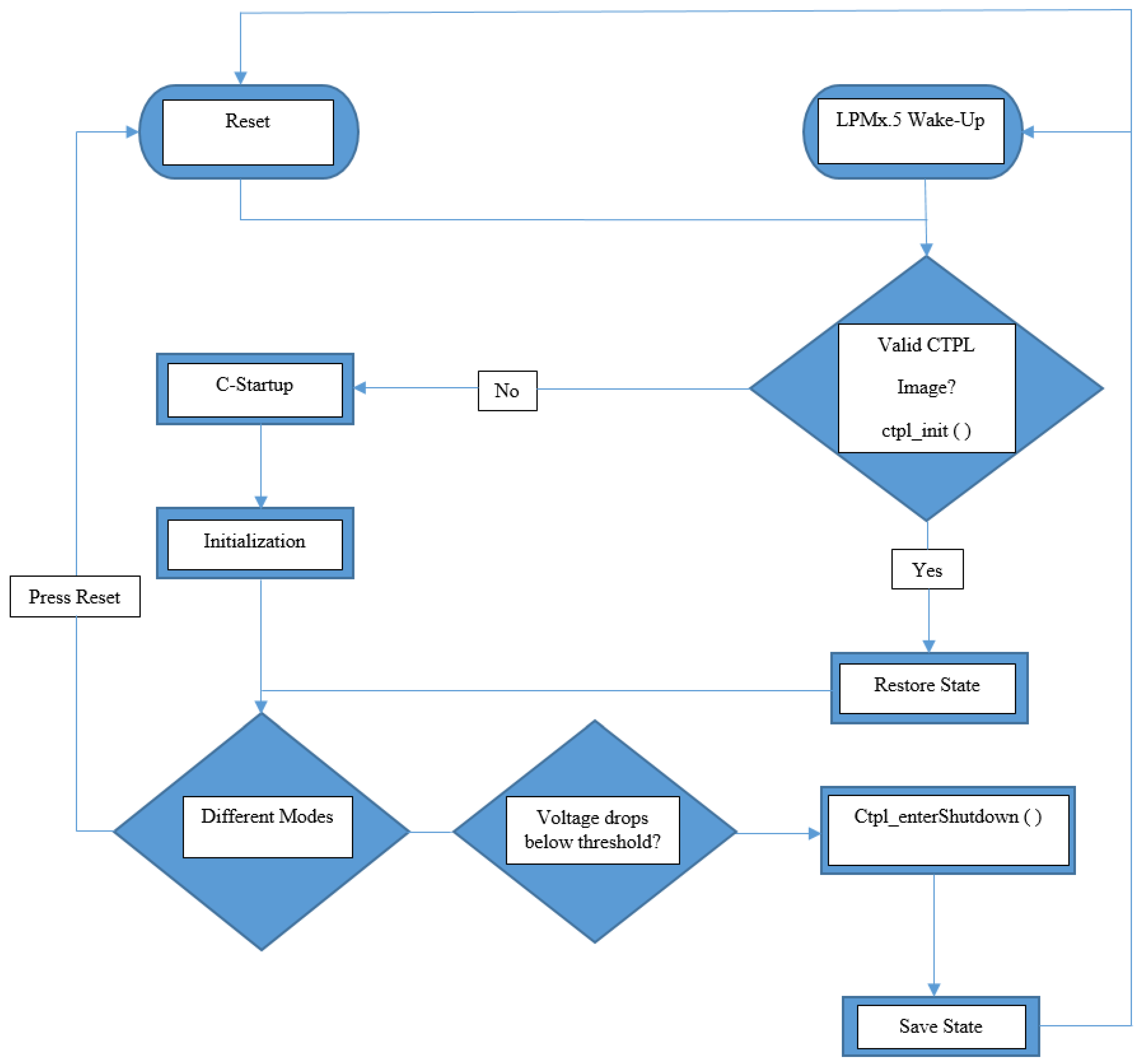
  28. Texas Instrument, Intelligent System State Restoration after Power Failure with Compute through Power Loss Utility. 2015. Available online: http://www.ti.com/lit/ug/tidu885/tidu885.pdf (accessed on 26 September 2016).
Figure 1. Schematic diagram of the self-developed RF-EH (five-stage voltage multiplier).
Electronics 05 00089 g001
Figure 2. Photograph of the two variants of the self-developed RF-EH circuit based on HP and SKYWORK manufactured diodes.
Electronics 05 00089 g002
Figure 3. Selected parts of Texas Instrument’s Compute through Power Loss Utility strategy used for implementing TC. The Ctpl_enterShutdown () function is triggered when the power supply voltage drops below the threshold. Adapted from [28].
Electronics 05 00089 g003
Figure 4. Block diagram of the experimental setup used to test TC with the FRAM-based microcontroller and radio link. It is possible to switch between a regulated DC power supply, energy harvesting kit (with onboard solar and TEG sources and external RF source), and the external solar panel. When the reference voltage on P1.5 lowers down to the value set in software, the ctpl_enterShutdown () software function is triggered; this can be verified on P4.0.
Electronics 05 00089 g004
Figure 5. Illustration of the toggling pattern. The threshold value is set in software to 2.5 V; thus, when the voltage drops below (here captured at 2.388 V), the state and data of the microcontroller is saved. This is followed by the toggling pattern that indicates the end of the CTPL function (the ctpl_enterShutdown () function continues to toggle the pin while waiting for the device to enter a BOR).
Electronics 05 00089 g005
Figure 6. Photograph of the experimental setup. Here, the external solar panel is used to power the FRAM-based microcontroller. The regulated DC power supply and multi-source EH kit can be seen in the background.
Electronics 05 00089 g006
Figure 7. Analytical model and measured output voltages for the RF-EH (five-stage voltage multiplier) at 5 cm, without a load.
Electronics 05 00089 g007
Figure 8. DC voltage at the fifth stage of the self-developed RF-EH board when powering the MSP-EXP430G2 kit. The distance between the TX and RX antennas is 2 cm.
Electronics 05 00089 g008
Figure 9. DC voltage at the fifth stage of the self-developed RF-EH board when powering the MSP-EXP430G2 kit. The distance between the TX and RX antennas is 5 cm.
Electronics 05 00089 g009
Figure 10. Analytical model and measured power for the TEG-EH source with different loads.
Electronics 05 00089 g010
Figure 11. Output voltage of the TEG module over time, when heated with the palm of the hand.
Electronics 05 00089 g011
Table 1. Measured voltage and current values with different nodes powered by the RF, solar, and TEG energy harvesters.
EH TechnologyNode’s Voltage [V]; Current [mA] MSP-EXP430G2Node’s Voltage [V]; Current [mA] EZ430-RF2500Node’s Voltage [V]; Current [mA] MSP-EXP430FR5739+CC2500
RF (900MHz@5 cm, 18 dBm)1.83; 0.0290.89; 2.210.001; 0.0
Solar (Panasonic AM-5412)3.2; 0.243.23; 0.19See Table 2 for values
TEG (CUI INC P85438)3.0; 0.252.8; 0.1822.35; 0.66
Table 2. First to fourth rows: measured voltage and current for the MSP-EXP430FR5739+CC2500 used as a transmitter. Fifth to eighth rows: measured voltage and current for the MSP-EXP430FR5739+CC2500 used as a receiver, both with the fixed power supply and the onboard solar panel (3 cm × 5 cm).
Source [V]Node Input [V]Node Output [V]Node Input [mA]
Main 3.33.332.52, No Radio
Main 3.33.332.537, With Radio
Solar EH3.3273.3252, No Radio
Solar EH2.1852.16729, With Radio
Main 3.33.33.106 2, No Radio
Main 3.33.33.10620, With Radio
Solar EH3.3263.2112.11, No Radio
Solar EH3.3243.112 20, With Radio
Table 3. First and second rows: measured voltage and current for the MSP-EXP430FR5739+CC2500 used as a transmitter. Third and fourth rows: measured voltage and current for the MSP-EXP430FR5739+CC2500 used as a receiver, with the larger solar panel (13.5 cm × 11.2 cm).
Parameters Case I (Outdoor Light)Case II (Indoor Light)Case III (Sharp Lamp Indoor Light)
Light Intensity [LUX]5.36 K1.46 K9.98 K
Voltage [V] and Current [mA] without radio3.063.103.5
2.462.002.16
Voltage [V] and Current [mA] with radio3.03.093.5
20.022.022.16
Voltage [V] and Current [mA] without radio3.03.103.5
2.162.002.16
Voltage [V] and Current [mA] with radio2.913.093.5
19.9822.022.16

