Article

Frequency Reconfigurable Quad-Element MIMO Antenna with Improved Isolation for 5G Systems

1
Department of Electronics and Communication Engineering, Feroze Gandhi Institute of Engineering and Technology, Reabareli 229316, India
2
Department of Electronics and Communication Engineering, SRM Institute of Science and Technology, Kattankulathur 603203, India
3
Department of Electronics and Communication Engineering, Government College of Engineering and Technology, Jammu 181122, India
4
Department of Electronics and Communication Engineering, Dr. B. R. Ambedkar National Institute of Technology, Jalandhar 144011, India
5
Department of Electronics and Communication Engineering, Noida Institute of Engineering and Technology, Greater Noida 201306, India
6
Smart Systems Engineering Laboratory, College of Engineering, Prince Sultan University, Riyadh 11586, Saudi Arabia
7
Department of Information Technology, College of Computer and Information Sciences, Princess Nourah bint Abdulrahman University, P.O. Box 84428, Riyadh 11671, Saudi Arabia
*
Authors to whom correspondence should be addressed.
Electronics 2023, 12(4), 796; https://doi.org/10.3390/electronics12040796
Submission received: 30 December 2022 / Revised: 29 January 2023 / Accepted: 3 February 2023 / Published: 5 February 2023
(This article belongs to the Special Issue Smart Antenna Optimization Techniques for Wireless Applications)

Abstract

:
In this paper, a frequency reconfigurable multiband multiple-input-multiple-output (MIMO) antenna is developed for 5G communication systems. The presented MIMO antenna element consists of a 50 Ω microstrip line, a rectangular monopole divided into two patches, and a partial ground plane. A split-ring resonator (SRR) is introduced into the upper patch to cover multiple 5G application bands, and an RF PIN diode is embedded between the upper and lower patches to enable the frequency diversity feature. In order to design a MIMO antenna with improved inter-element isolation, four antenna elements are orthogonally located with ground planes connected to each other. The antenna design covers the n41/n46/n48/n79 5G application bands. The prototype MIMO antenna is developed on the FR-4 substrate, and the measured results match with the simulated outcomes. The overall footprint of the prototype antenna is 70 × 70 × 1.6 mm3.

1. Introduction

Modern communication devices support multiple wireless standards to achieve high data rate transmission. The multiple-input-multiple-output (MIMO) system exhibiting frequency diversity is an excellent choice for improved coverage and higher data rates. Of late, different techniques have been reported for antenna miniaturization, multiband operation, and frequency diversity [1,2]. However, coupling amongst resonating elements is a challenge in MIMO antenna designs. The inter-element coupling in densely packed MIMO antennas can be encountered by using parasitic reflectors, defected ground planes, neutralization lines, and decoupling elements such as split-ring resonators (SRR) [1,2,3]. Several MIMO antenna designs have been described in recent years [4,5,6,7,8,9,10,11,12,13,14,15,16,17,18,19,20,21,22,23,24,25,26,27,28,29,30,31,32,33,34,35]. In ref. [3], different substrate materials were investigated for the sub-6 GHz band. In ref. [4], a single-band four-port MIMO antenna configuration was reported for the n79 5G band, where the antenna elements were arranged orthogonally to decrease mutual coupling. A MIMO antenna with orthogonally arranged antenna elements covering the 3.4–3.6 GHz band was reported in [5]. However, multiple defects were introduced on the ground plane [4,5], which impacts the radiation performance of the antenna. In ref. [6], a double-layered meta-surface antenna was proposed with improved gain and isolation for the sub-6 GHz 5G band. However, the reported antenna design complexity was high while occupying more substrate area. In ref. [7], a coplanar waveguide (CPW)-fed two-element MIMO antenna with interconnected ground planes was presented. Reconfigurable antenna designs for sub-6 GHz 5G systems were reported in [8,9]. However, the antenna designs investigated in [8,9] require a greater number of active elements 2/4 RF PIN diodes to achieve reconfigurability. In ref. [10], a quad-port log-periodic dipole antenna array was investigated with epsilon near zero metamaterial for the upper 5G application band. In refs. [11,12], circularly polarized quad-port MIMO antenna designs were presented for ultra-wideband and sub-6 GHz bands. The antenna design examined in [12] demonstrated a single band of operation and a lower isolation level, as well as isolated ground planes, limiting its practical application. Dual-port wearable MIMO antenna designs with circular and liner polarization were studied in [13,14].
Various designs of four-port MIMO antennas with and without notched bands were analyzed for wideband applications in [15,16,17]. In refs. [18,19], MIMO antennas were reported for Bluetooth/WLAN applications. A frequency agile MIMO antenna for cognitive systems was investigated in [20], where a stop band filter was used to reduce mutual coupling. In refs. [21,22], eight-port MIMO antennas were presented for 5G smartphones. In ref. [21], loop antennas were printed on non-metal frames for the 3.4–3.6 GHz band, whereas CPW-fed T-ring antenna elements were employed in [22]. However, the reported eight-port MIMO antenna designs demonstrated a single band of operation. In refs. [23,24,25], SRR and parasitic elements were loaded between antenna elements to improve isolation. However, these antenna configurations demonstrated a lower level of inter-element isolation and fixed-band operation. Dual-port MIMO antennas with frequency diversity were investigated in [26,27,28,29,30,31,32]. In ref. [26], a frequency agile MIMO antenna operating in multiple modes was investigated for cognitive radio. A tunable antenna with a varactor diode embedded in the ground plane was reported in [27]. In ref. [28], an RF-MEMS switch was integrated into an antenna to operate in multiple bands by changing the switch’s operating mode. The coupling conductors and PIN diodes were used to switch between upper/lower WLAN and m-WiMAX systems in [29]. Varactor diodes were implanted at the end of the feed line in [30] to tune its operating band for low-frequency applications. However, the reported design consumed more substrate area. In ref. [31], a Yagi-Uda antenna integrated with a varactor diode was investigated. But, the double-layer fabrication adds complexity and limits the practical applications of the presented antenna. In ref. [32], a dual-band MIMO antenna was proposed with frequency diversity. In ref. [33], a four-port MIMO antenna was proposed with fixed band operation for 5G. In refs. [34,35], four-element MIMO antennas with frequency diversity were designed, where varactor diodes and RF MEMS were implanted in SRR and rectangular slots for frequency diversity. However, the above-reported [29,30,31,32,33,34,35] antenna configurations required more substrate volume, a greater number of active elements/switches, which complicates antenna design, and high inter-element coupling. Poor isolation implies that adjacent resonators are correlated, resulting in poor antenna performance.
In this work, a quad-element frequency agile MIMO antenna is developed for n41/n46/n48/n79 5G bands. The radiator of the MIMO antenna consists of a rectangular monopole divided into two patches and a partial ground plane. Also, an SRR is introduced into the upper patch and an RF PIN diode is embedded between the upper and lower patches to enable the frequency diversity feature. The four radiating elements are arranged orthogonally with an inter-element distance of 0.17λ0 to improve isolation, where λ0 is calculated at the lowest operating band. The presented frequency agile antenna is simple to design and can be easily integrated with other RF devices due to the connected ground planes of the resonators. The antenna has a reasonable gain, excellent inter-element isolation, and covers a wide range of 5G application bands. The introduction is presented in Section 1, Section 2 presents the antenna element and MIMO antenna arrangement, Section 3 shows the results of the proposed MIMO antenna, Section 4 presents the MIMO/diversity parameters, and Section 5 states the conclusion of the proposed work.

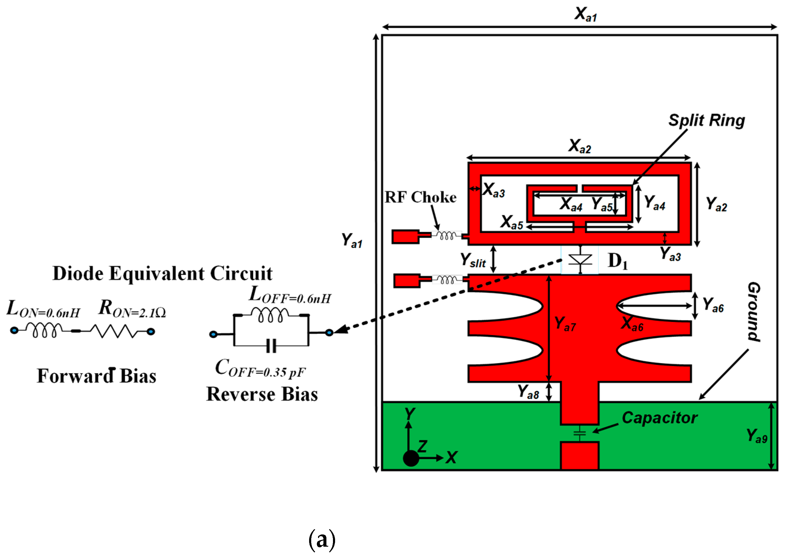
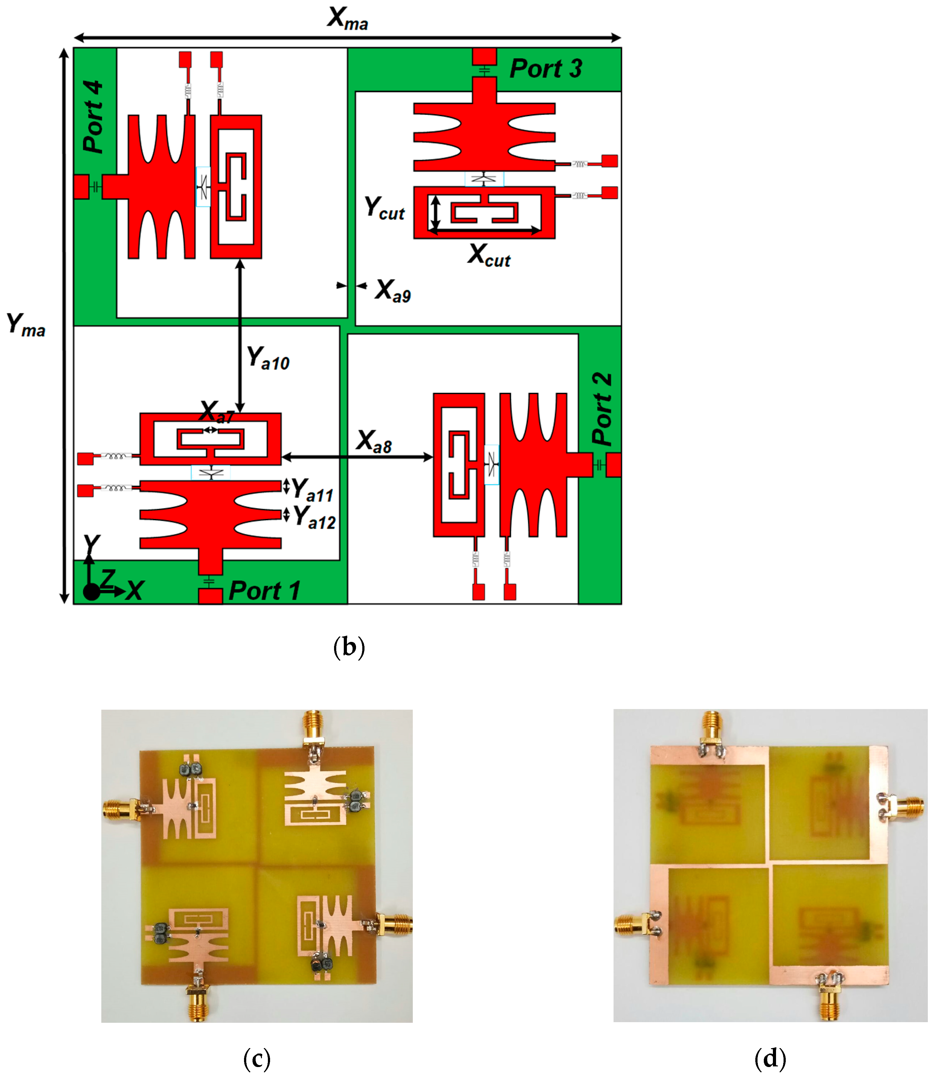
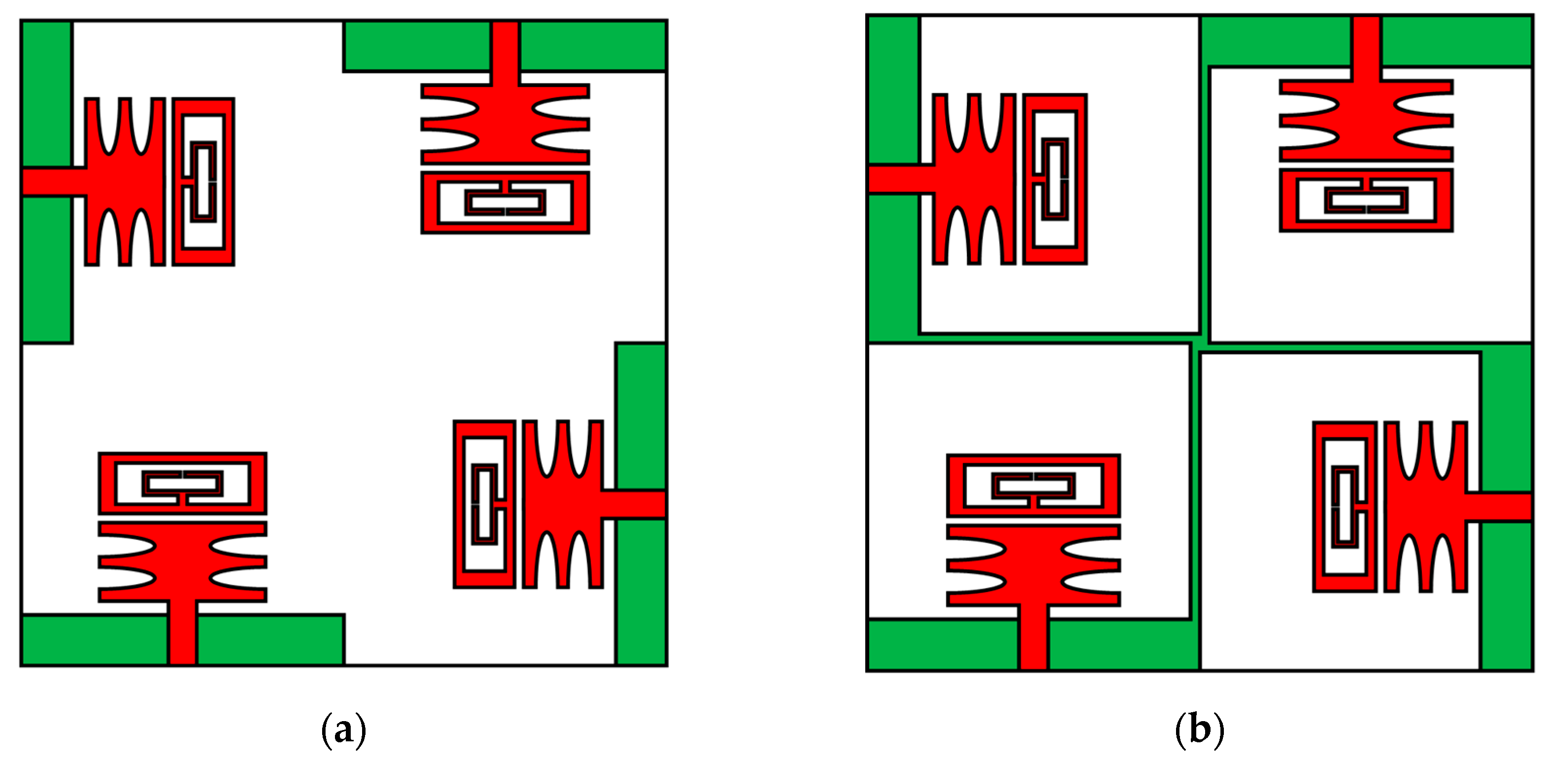
2. Antenna Configuration

Figure 1a shows a schematic of the proposed antenna element. The antenna element consists of a feed line, two radiators connected through a PIN diode, and a partial ground plane. The lower rectangular-shaped patch is truncated with a pair of ellipses on its edges to lengthen the current path. The upper patch is composed of a rectangular ring and an SRR. The four-unit cells are organized orthogonally to develop a MIMO antenna, as shown in Figure 1b. The ground surfaces of the antenna elements are connected to an equal voltage level in the MIMO arrangement. The antenna is developed on the FR-4 substrate with a relative permittivity of 4.4, and the simulations are performed in the ANSYS HFSS software. The overall volume of the proposed MIMO antenna structure is 70 × 70 × 1.60 mm3, and its physical dimensions are shown in Table 1. Figure 1c,d shows photographs of the top and back sides of the MIMO antenna prototype, respectively.

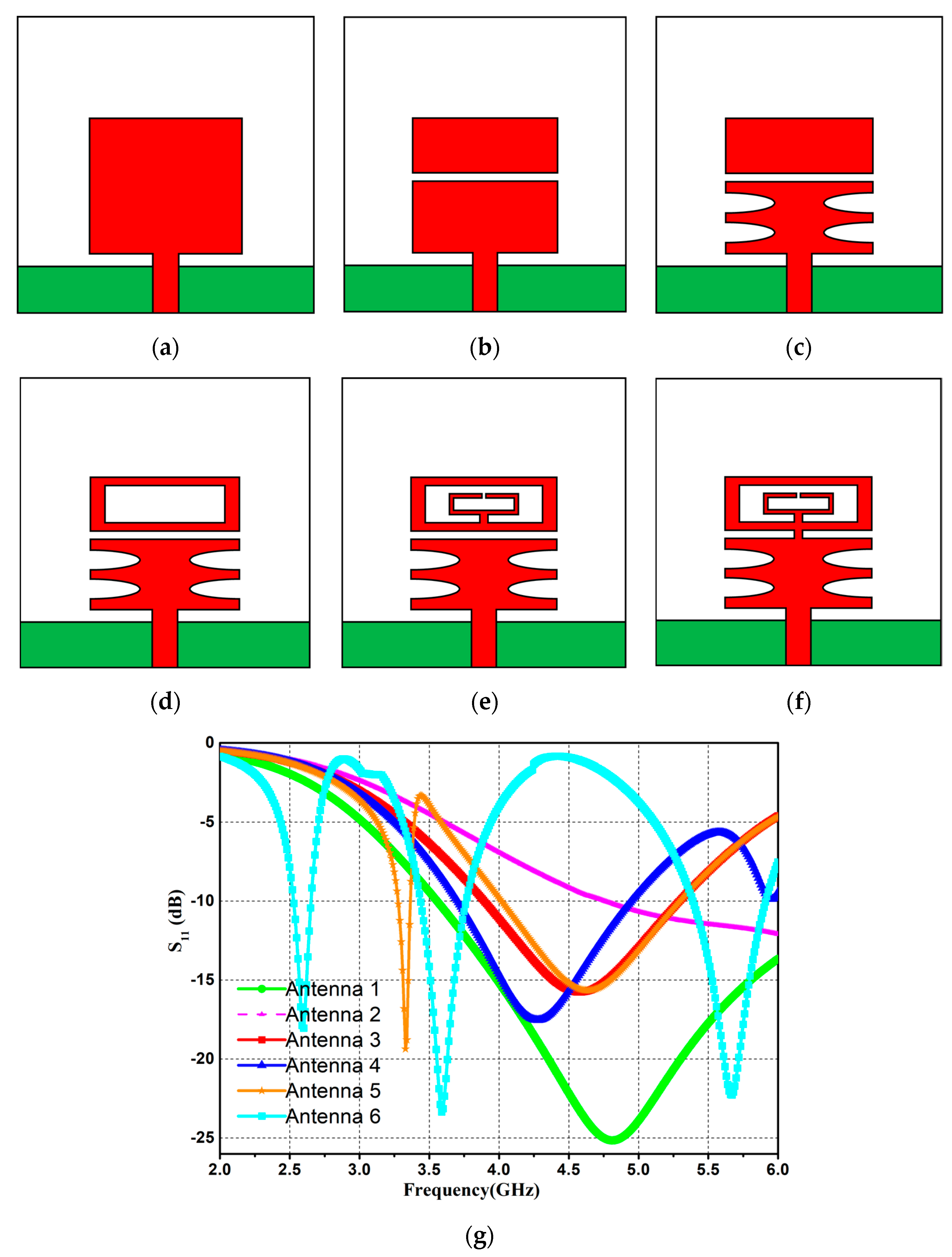
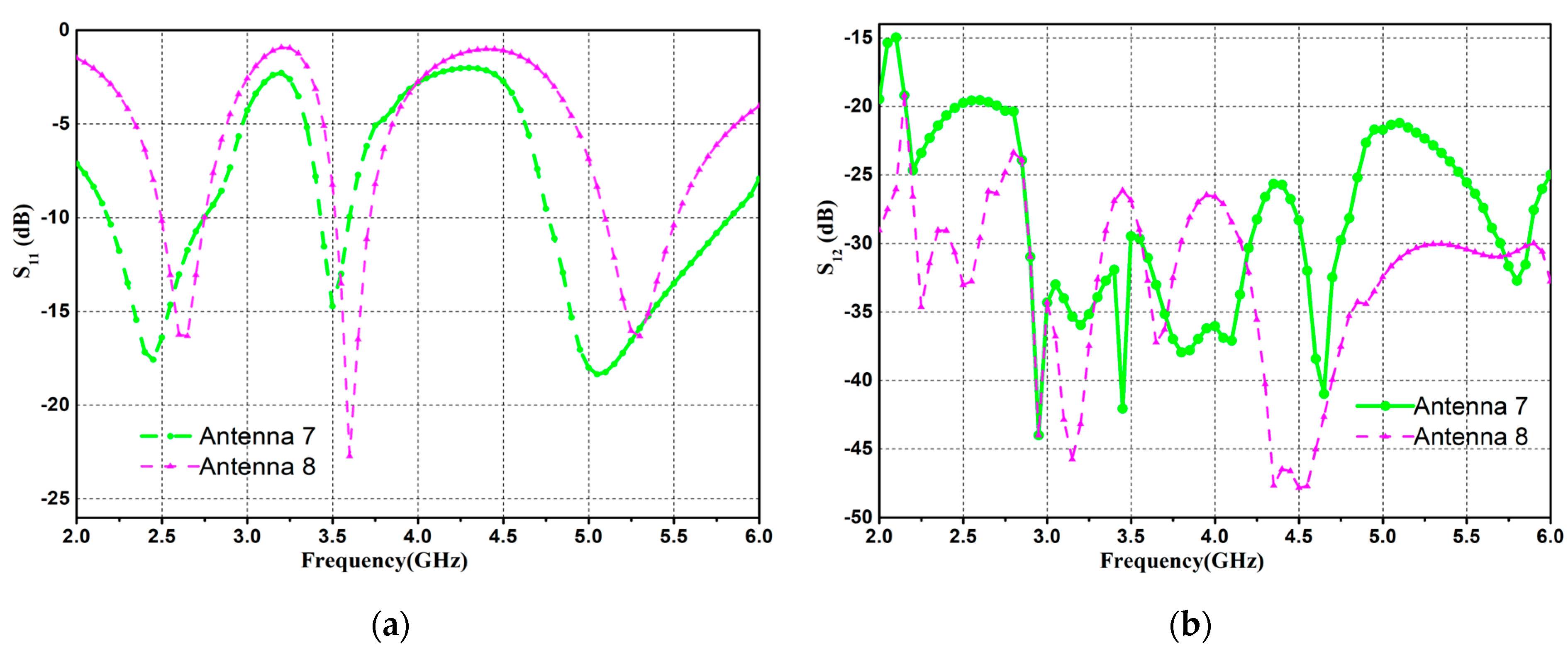
Evolution Steps of the Antenna

Figure 2 depicts the design steps of the antenna element. The resonating frequency of the antenna element is evaluated as [11]
f c = c 2 ε r m L 2 + n W 2
where c is the speed of light in vacuum, fc is the center frequency, and L and W are the length and width of the patch antenna, respectively. Initially, a rectangular radiator with dimensions of 18 mm × 16 mm (antenna-1), is developed for a center frequency of 4.80 GHz, as shown in Figure 2a. The scattering parameters of the design stages are displayed in Figure 2g. In the second step, antenna-1 is divided into two patches, resulting in antenna-2, as shown in Figure 2b. The resonating band of antenna-2 shifts to the higher frequency side. The lower patch of antenna-2 is modified by etching a pair of ellipses (antenna-3), as shown in Figure 2c. Then, a rectangular slot (size of 4.5 mm × 14.5 mm) is etched out from the upper patch (shown in Figure 2d), resulting in antenna-4, which resonates at 4.30 GHz.
In the next step, an SRR is loaded into the upper patch of antenna-4, shown in Figure 2e, resulting in dual-band operation (antenna-5) at 3.30 GHz and 4.60 GHz. Then, a 1 mm × 1 mm metal strip is embedded between the lower and upper patches, resulting in the development of antenna-6, shown in Figure 2f. The antenna-6 resonates at 2.50 GHz, 3.50 GHz, and 5.20 GHz. The metal strip is used as an RF PIN diode to switch the operating states of the antenna elements. When diodes are in the OFF state, the antenna element function as antenna-5 with two operating bands, while in the ON state, it functions as antenna-6 with three operating bands.
The parametric analysis of the antenna element is shown in Figure 3. When performing parametric analysis, when Xcut is changed from 14 to 15 mm in 0.5 mm steps, the frequency of 3.5 GHz changes, as shown in Figure 3a, whereas when Xa6 changes from 5.5 to 6.5 mm in 0.5 mm steps, the upper band changes, as illustrated in Figure 3b. Similarly, when Xa5 changes from 8.0 to 9.0 mm, the center band changes, as illustrated in Figure 3c. Consequently, the optimum values of Xcut, Xa6, and Xa5 are considered 14.5 mm, 6.0 mm, and 8.5 mm, respectively.
Figure 4 depicts the design steps of the MIMO antenna. In the proposed design, four identical antenna elements are placed orthogonally, as shown in Figure 4a. Also, in order to make practical use of the developed antenna, the ground planes of all four elements are connected by a metal strip of a width of 1 mm, as shown in Figure 4b. The ground planes of the MIMO antenna elements are connected to form a common reference plane for practical systems, where voltage should have a common signal level, that is, zero or ground level. In split ground MIMO antenna designs, it cannot be promised that the MIMO system will work efficiently, as the assumption that all ground planes have the same voltage level becomes invalid [36]. The inter-element distance is kept as 0.17λ0, where λ0 is calculated at the lowest operating band (2.50 GHz), and the isolation level is satisfactory without the use of any special/complex decoupling or isolation network. Figure 5 depicts the scattering (reflection and transmission) parameters of the presented MIMO antenna.
In the presented MIMO antenna, the inter-element isolation is greater than 28 dB, whereas the 5G MIMO antennas studied in [4,5,6,12,21,22,23,24,25,28,33] had a lower isolation level. Since the antenna elements are orthogonal to each other, the direction of the coupling current vectors differs from each other. Due to the metal strip and orthogonal arrangement of the resonating elements, which supports polarization diversity, the proposed MIMO/diversity antenna could achieve high isolation. The higher level of isolation implies that adjacent elements are uncorrelated, resulting in maximum channel capacity.

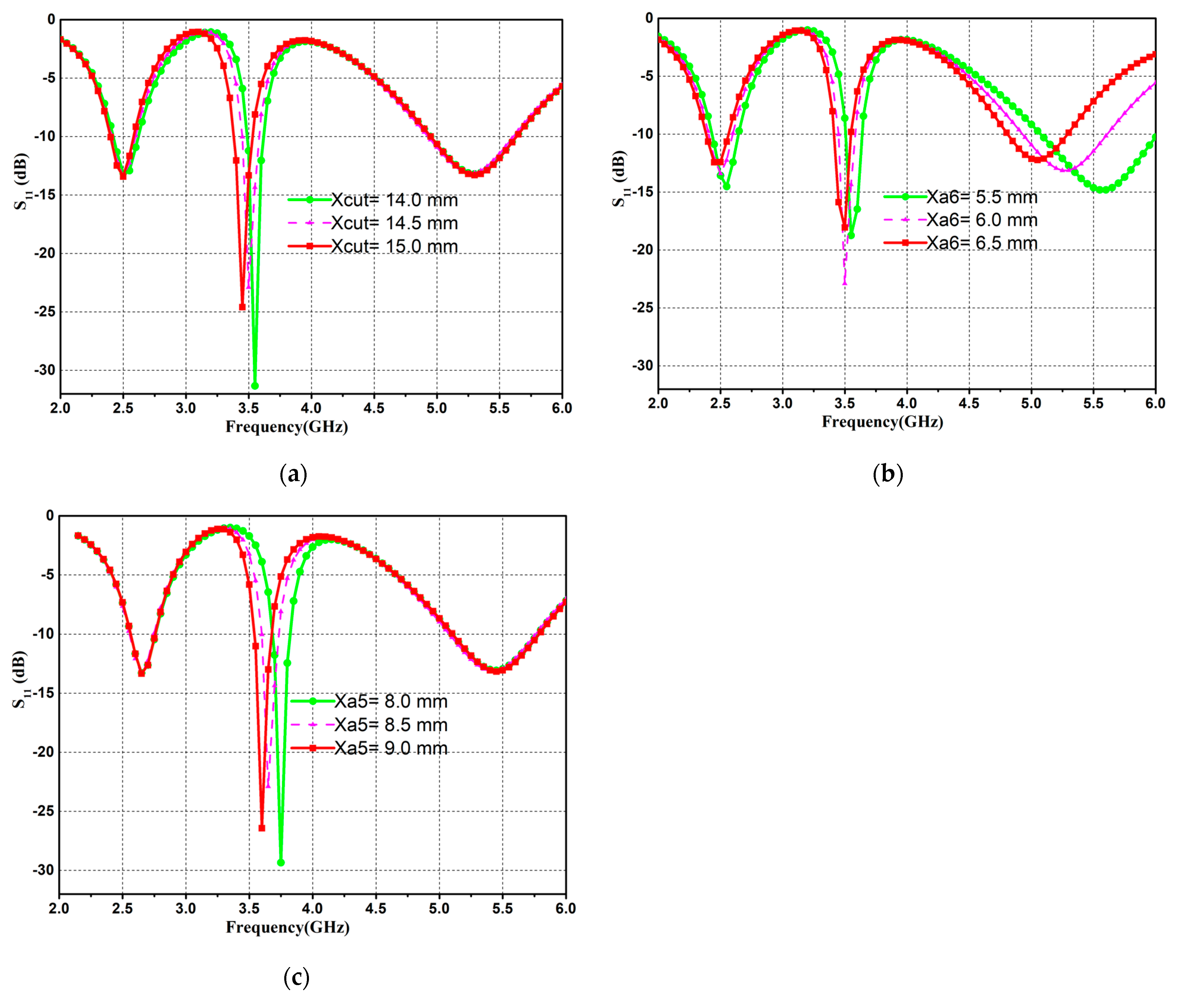
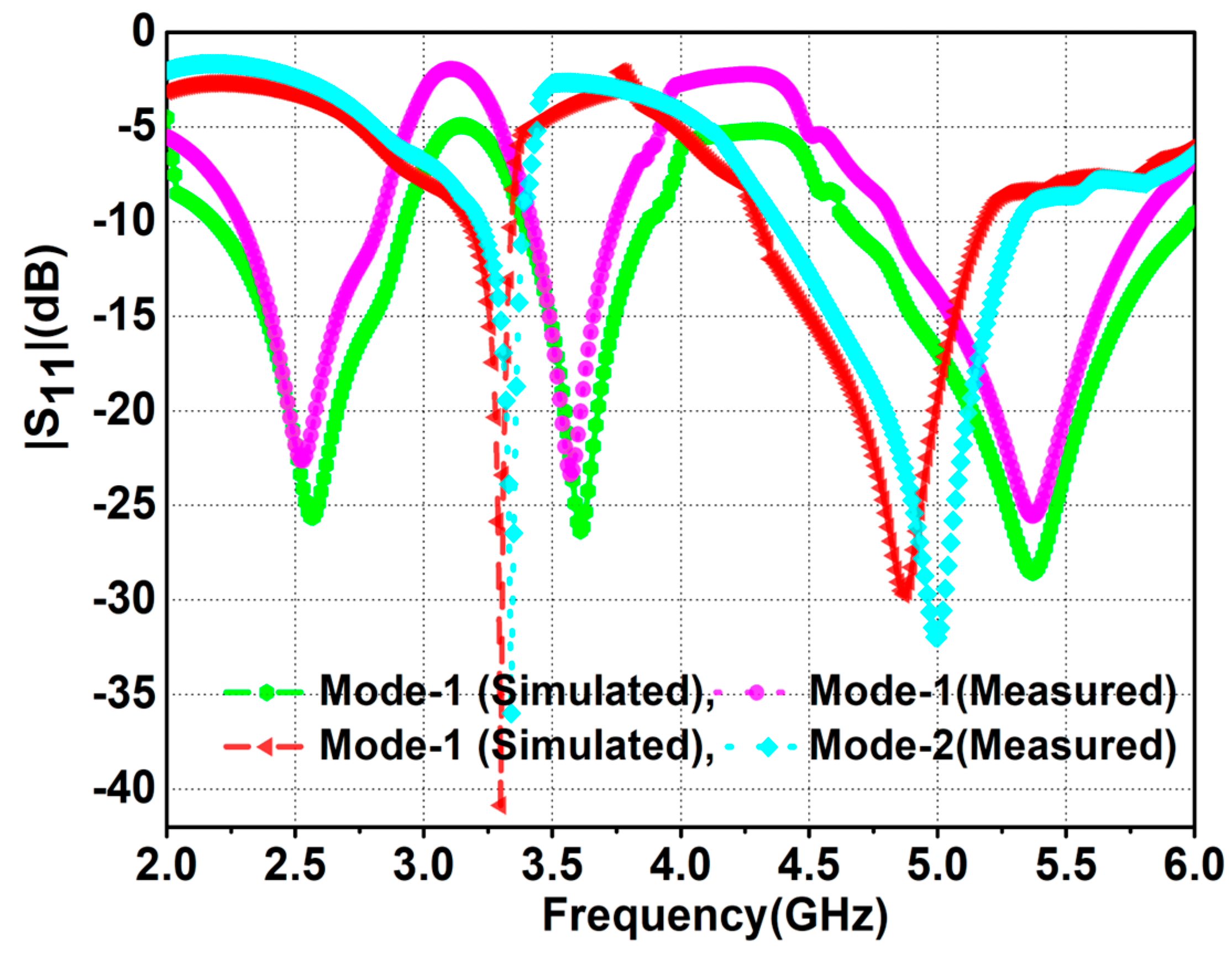
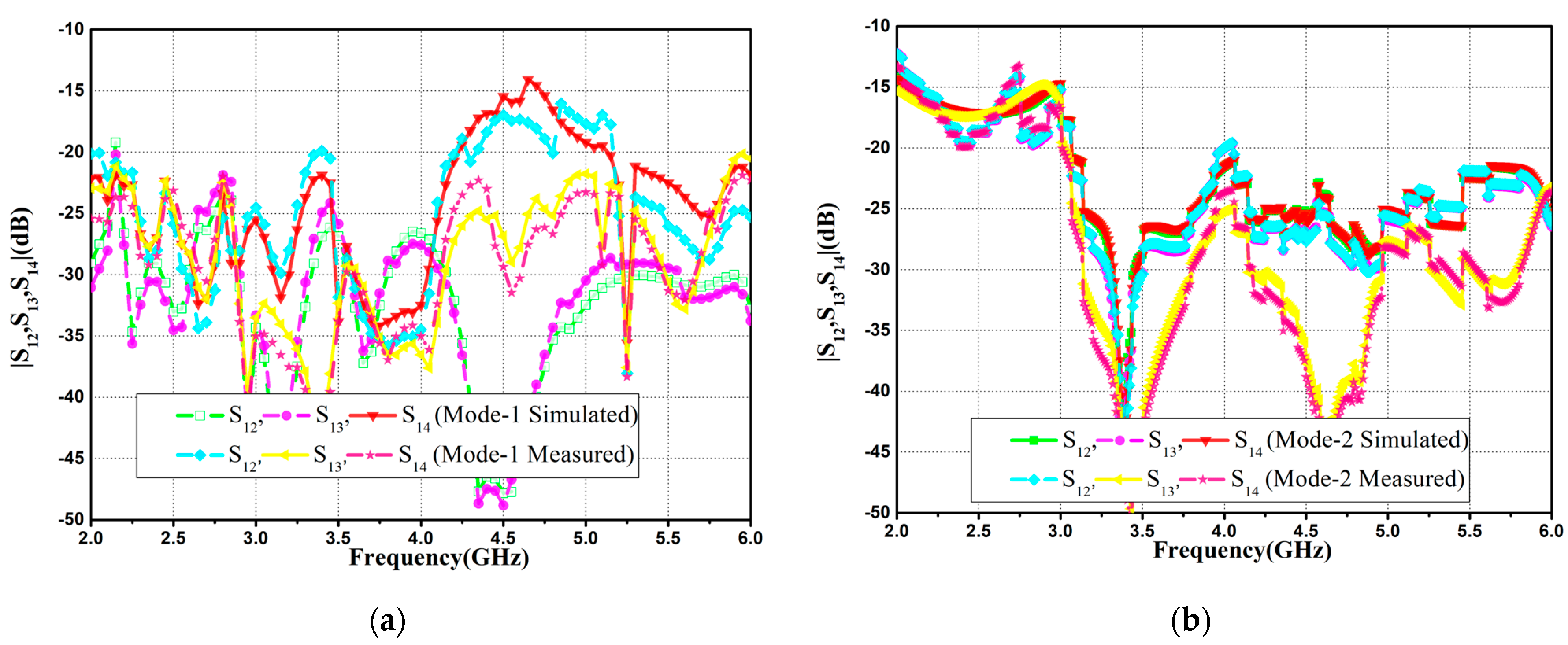
3. Results and Discussion

The prospective frequency agile quad-port MIMO antenna physical size is 70 × 70 × 1.60 mm3. Modifications to the lower patch result in antenna element miniaturization, whereas etching a slot and loading an SRR to the upper patch results in multiband operation. The frequency diversity feature is enabled by inserting RF PIN diodes between the lower and upper patches by changing the operating state of the diodes. When the diode is in the ON state, antenna operation is referred to as state-1, and when the diode is turned OFF, antenna operation is referred to as state-2. In state-1, both patches (lower and upper) are physically connected, and the antenna operates in tri-band mode with center frequencies of 2.50 GHz, 3.50 GHz, and 5.20 GHz, covering the n41, n46, and n48 bands, respectively.
Figure 6 depicts the simulated and measured scattering attributes of the MIMO antenna design for the working states. During simulation, the PIN diode (BAP64-02 NXP) is modeled with metal strips by assigning different RLC boundary conditions for modes-1 and -2. A 20 pF DC blocking capacitor and a 22 nH inductor are used to separate biasing and excitation supply (DC/RF). Also, the biasing lines are printed in such a way that their influence on resonator performance is minimized. The small metal pads of 1 mm × 1 mm are used for the biasing circuit. The PNA-L series vector network analyzer is used for the measurement of reflection coefficients, which are plotted in Figure 6. A very small difference between experimental and simulated outcomes is seen, which is due to fabrication tolerance and SMD device pasting. Table 2 presents a summary of the simulated and measured results.

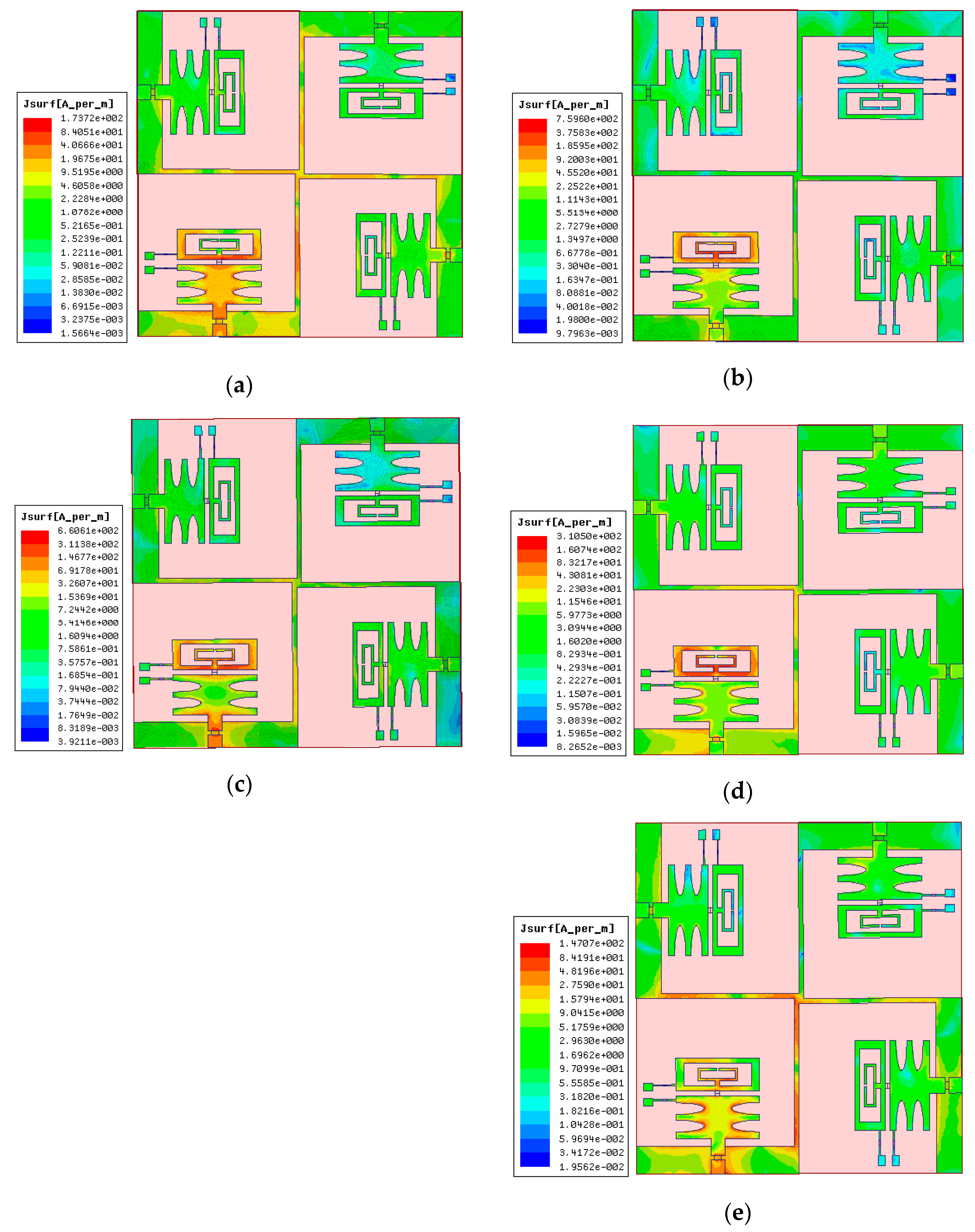
3.1. Surface Current Distribution

The surface current and mutual coupling of the MIMO antenna are analyzed and plotted in Figure 7 and Figure 8, respectively. The density of coupling current from element-1 to elements-2, -3, and -4 is too weak, as shown in Figure 7, which results in improved isolation.

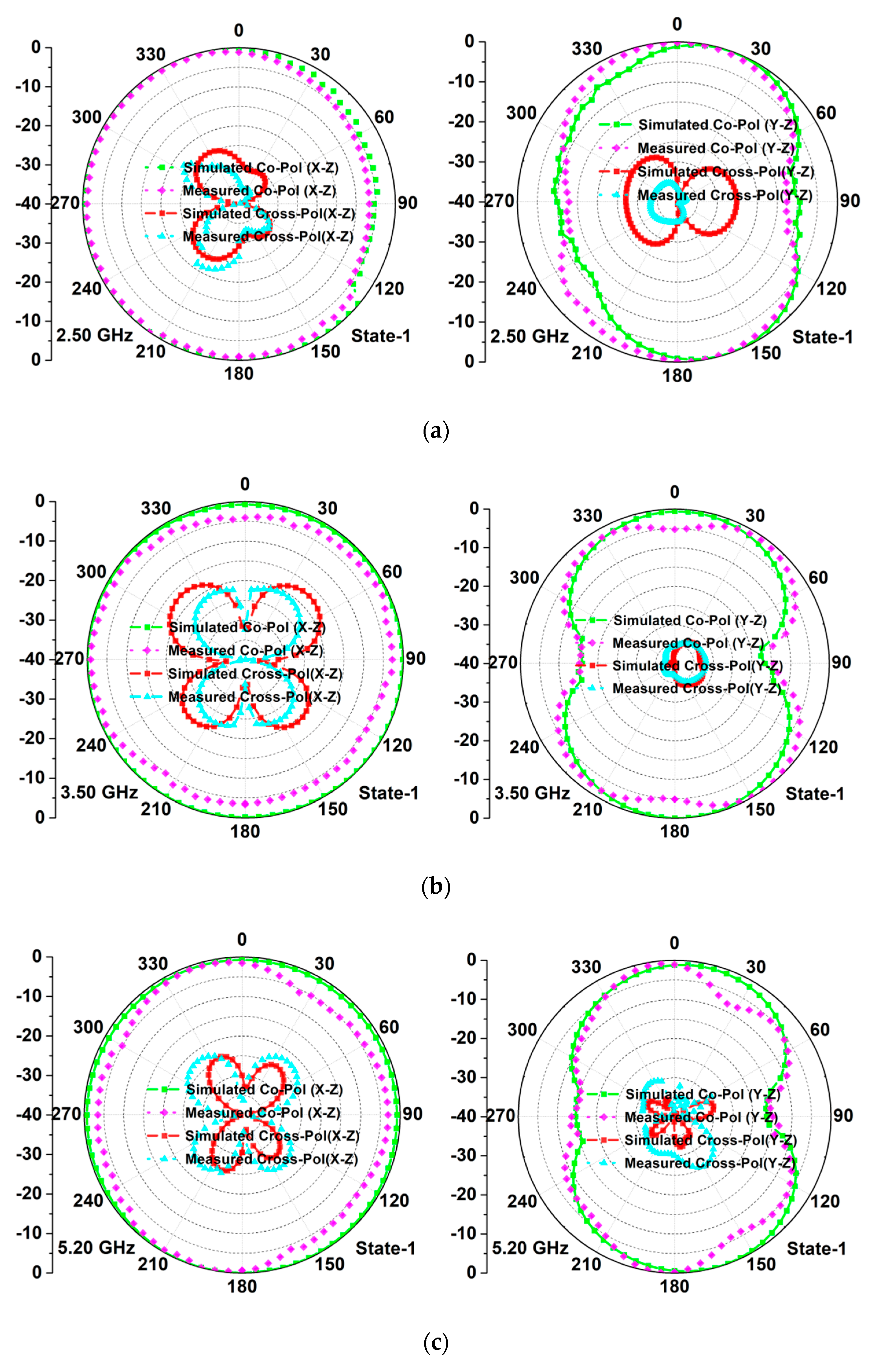
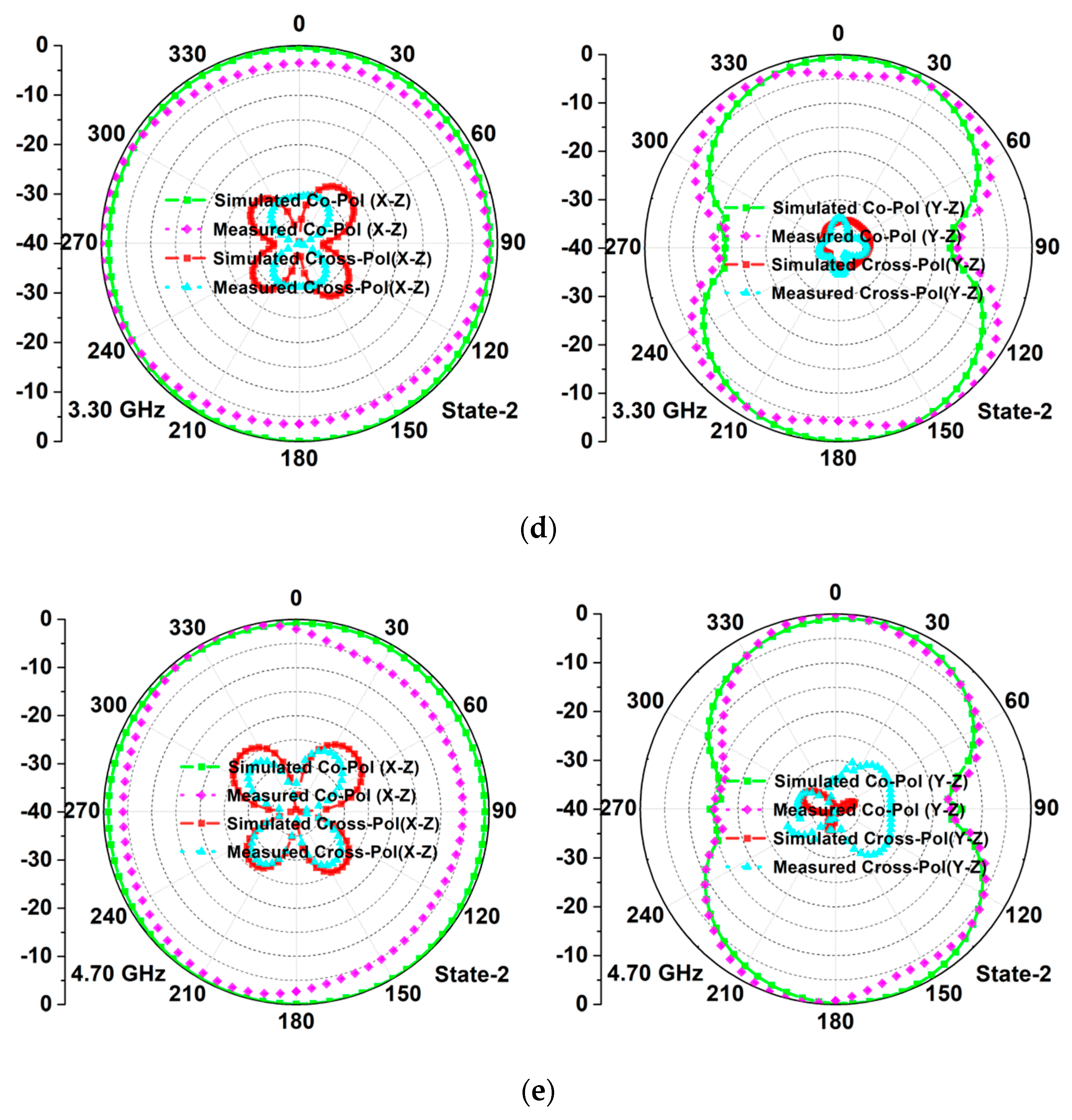
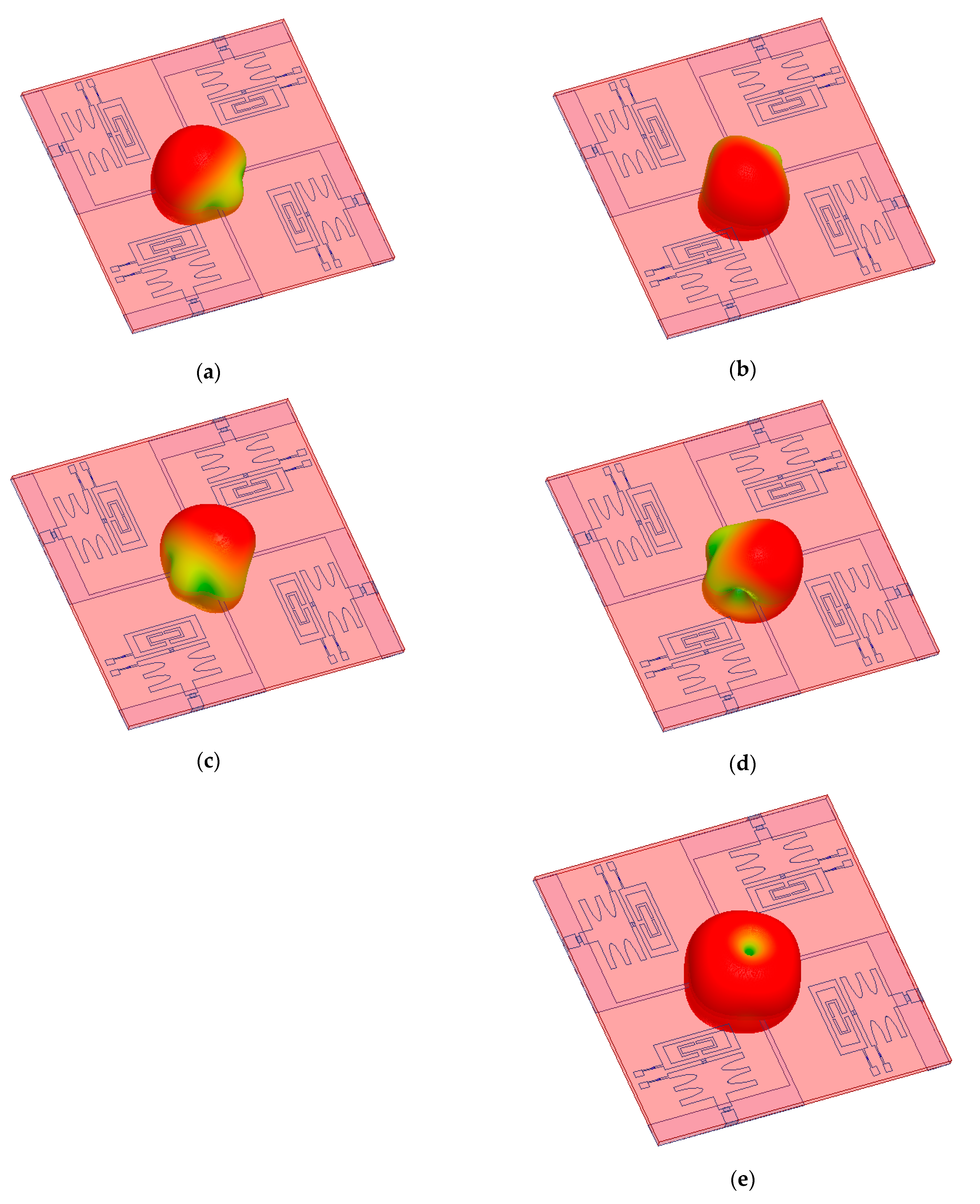
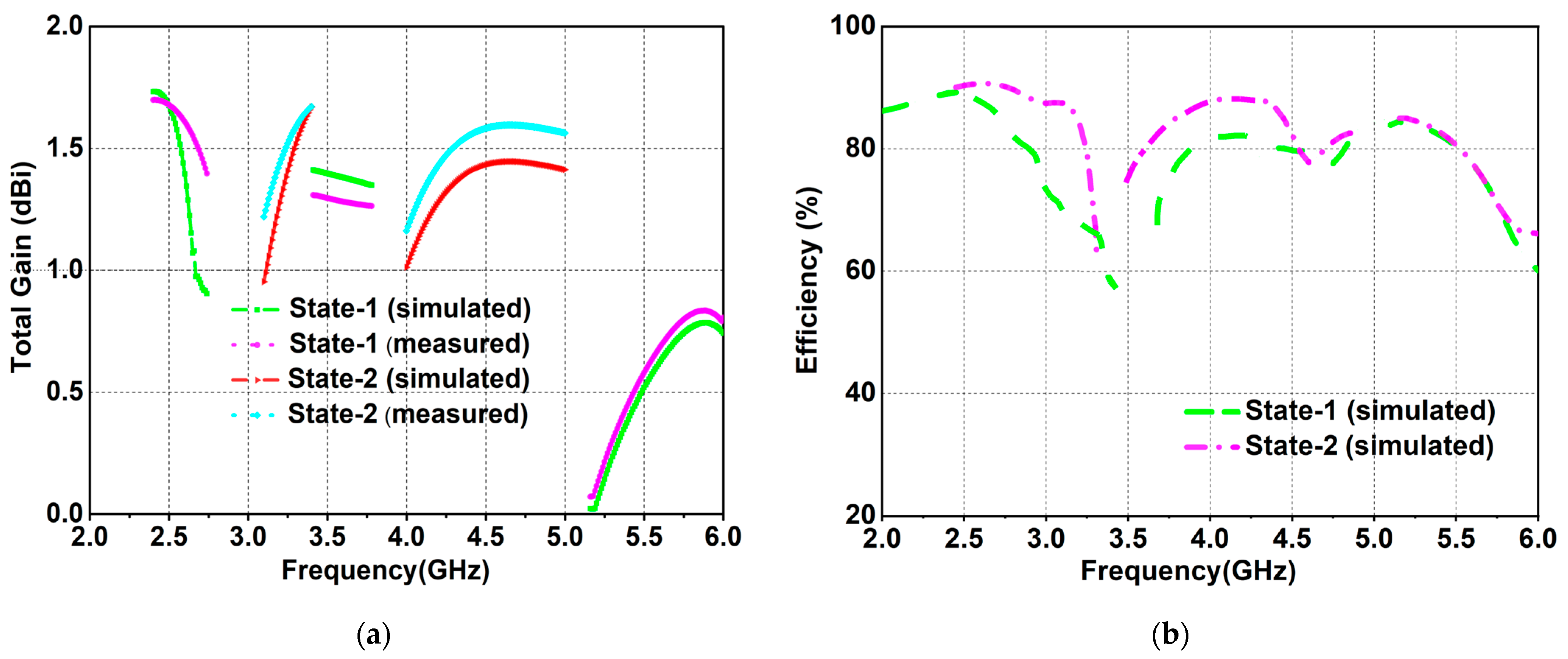
3.2. Radiation Attributes and Gain

To characterize the far-field performance of the developed quad-element MIMO antenna, its 2-D radiation attributes (for modes-1 and -2) are plotted in Figure 9. The radiation graphs illustrate that the antenna exhibits a high level of cross-polarization (>20 dB) for both planes across all operating bands. This is validated by comparing simulated and experimental data. Figure 10a–d present 3-D polar plots of the developed MIMO antenna when individual ports (1, 2, 3, and 4) are in the ON state, and Figure 10e shows when all antenna elements (1–4) are excited (ON state) at the same time. The gain and efficiency curves of the antenna are shown in Figure 11a,b, respectively. The antenna exhibits stable gain performance for both working modes.

4. MIMO/Diversity Parameters

The various diversity parameters (envelope correlation coefficient (ECC), diversity gain (DG), and total active reflection coefficient (TARC)) are computed to validate the MIMO antenna design and are plotted in Figure 12 for modes-1 and -2.

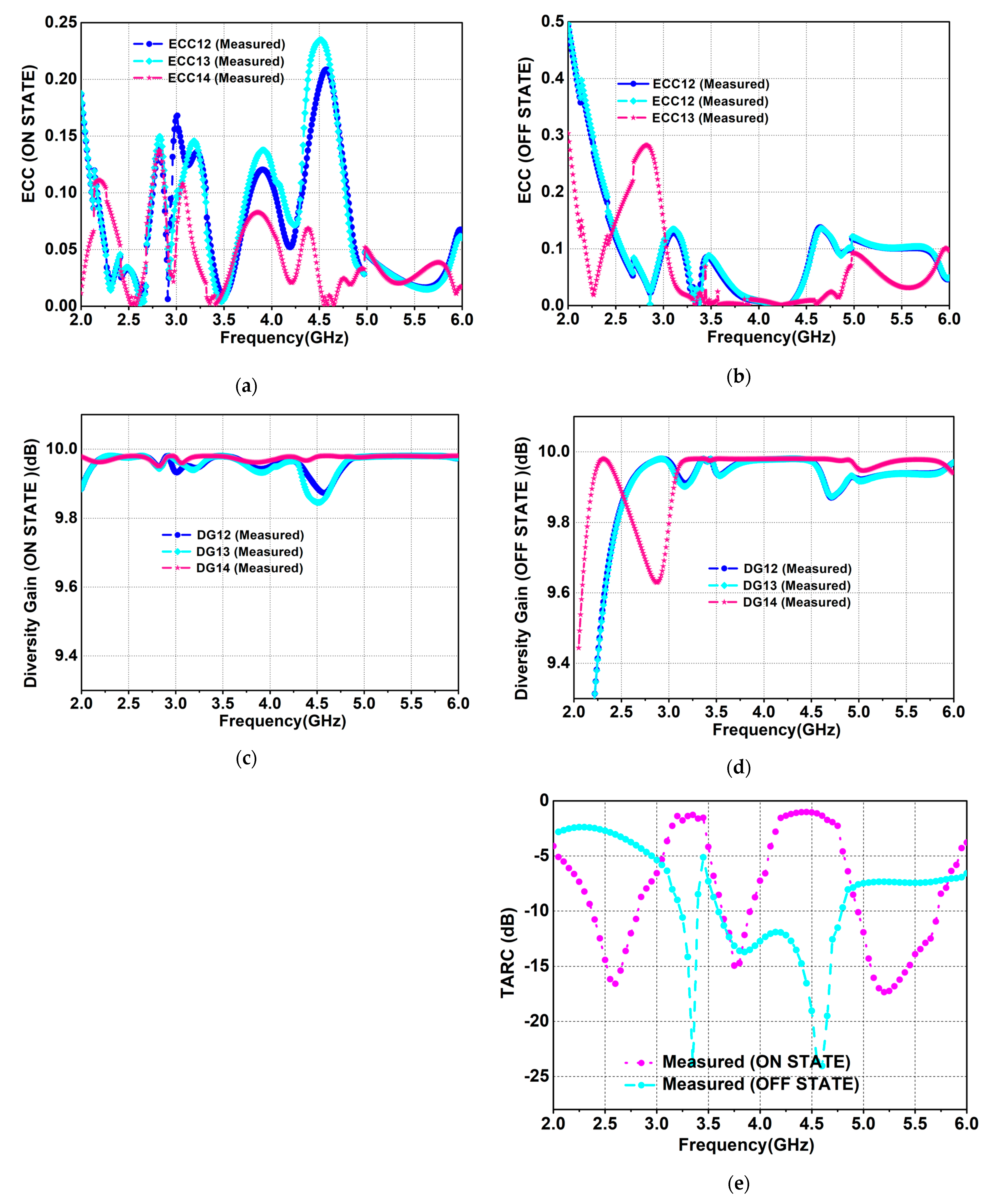
4.1. Envelope Correlation Coefficient (ECC)

The ECC is a measure of the coupling current between MIMO antenna elements. ECC varies with the physical orientation/arrangement of the antenna elements, and for practical implementation, its numerical value should be <0.5. A low ECC indicates that the antenna elements are uncorrelated to one another and that less power is coupled to other elements in the vicinity of the excited element. The following expressions are used to calculate the ECC [37,38].
E C C p × q = 4 π F 1 ( θ , ϕ )   ×   F 2 ( θ , ϕ )   × F 3 ( θ , ϕ )   ×   F 4 ( θ , ϕ )   d Ω 4 4 π F 1 ( θ , ϕ ) 4 d Ω F 2 ( θ , ϕ ) 4 d Ω F 3 ( θ , ϕ ) 4 d Ω F 4 ( θ , ϕ ) 4 d Ω
where F i θ ,   ϕ is the radiation pattern of the antenna when the ith port is excited. For a quad-port (N = 4) system, the ECC between elements i = 1 and j = 2 is expressed as
E C C 1 ,   2 ,   4 = S 11 * S 12 + S 21 * S 22 + S 13 * S 32 + S 14 * S 42 2 1 S 11 2 S 21 2 S 31 2 S 41 2 1 S 12 2 S 22 2 S 32 2 S 42 2
The ECC between other ports can be calculated by changing the values of i and j. The ECC is calculated using S-parameters for the presented MIMO antenna, and it is found to be less than 0.3 between various antenna ports.

4.2. Diversity Gain (DG)

Another diversity parameter for validating MIMO configuration is DG. DG demonstrates the superiority of the MIMO over the SISO system. It must ideally be close to 10 dB. The DG is related to ECC and is calculated using the following expression [39].
D G p × q   =   10 1 E C C p × q 2

4.3. Total Active Reflection Coefficient (TARC)

TARC is also an important attribute to validate diversity performance in terms of incident and reflected powers. In a lossless system, TARC can be computed using scattering parameters, but practically, it must also consider frequency and scan angle. TARC values can be calculated using the following relation [13].
TARC = i = 1 q S i 1 + p = 2 q S i p e i θ p 1 2 q
It is clear from Figure 12 that the measured and simulated values of the MIMO/diversity parameters, ECC (<0.5), DG (~10 dB), and TARC (<−10 dB), are within acceptable limits.
Table 3 shows a comparative analysis of the developed frequency agile quad-port MIMO antenna and existing MIMO antennas. The MIMO antenna designs investigated in [6,12] were quad-port with isolated ground planes, but demonstrated single-band operation. The four-port MIMO antenna designs investigated in [6,33] occupied more substrate area and were not frequency agile. The four-element MIMO antenna designs proposed in [4,24] were compact, but had fixed single- or dual-band operation. The MIMO antennas reported in [20,23,25,27,28] were only two-port antenna configurations, with only a few designs displaying frequency diversity.

5. Conclusions

In this paper, a frequency agile quad-port MIMO antenna is designed and tested for multiple 5G application bands. The MIMO elements are made up of two patches, where the lower patch edges are modified by etching a pair of ellipses to increase the current path to achieve miniaturization. The upper patch is slotted and loaded with an SRR to achieve multiband operation. An RF PIN diode is embedded between both patches (lower and upper) to enable the frequency diversity feature, enabling the presented antenna structure to achieve multi-functionality. The antenna is developed on the FR-4 substrate, which is a low-cost substrate, and occupies a relatively small area. The antenna has a reasonable gain, which can be further increased by employing a reflector or meta-surface placed at the back side of the radiator at an appropriate distance. Furthermore, the orthogonal placement of the radiating elements on the edges of the antenna’s substrate (with an inter-element distance of 0.17λ0, where λ0 is calculated at the lowest operating band) for high isolation, and a connected ground plane makes it a suitable candidate for the 5G application bands n41/n46/n48/n79.

Author Contributions

Conceptualization, G.S. and S.K.; formal analysis, A.A., B.K.K. and V.K.P.; investigation, G.S., M.M. and H.M.; writing—original draft preparation, G.S.; writing—review and editing, G.S., S.K. and A.A.; supervision, M.M. and H.M. All authors have read and agreed to the published version of the manuscript.

Funding

Princess Nourah bint Abdulrahman University Researchers Supporting Project number (PNURSP2023R137), Princess Nourah bint Abdulrahman University, Riyadh, Saudi Arabia.

Institutional Review Board Statement

Not applicable.

Informed Consent Statement

Not applicable.

Data Availability Statement

Not applicable.

Acknowledgments

Mohamed Marey acknowledges the support of Prince Sultan University.

Conflicts of Interest

The authors declare no conflict of interest.

References

  1. Singh, G.; Kumar, S.; Kanaujia, B.K.; Pandey, V.K. Design and implementation of a compact tri-band four-port multiple-input-multiple-output antenna. Int. J. RF Microw. Comput. Aided Eng. 2022, 32, e23218. [Google Scholar] [CrossRef]
  2. Singh, G.; Kumar, S.; Kanaujia, B.K.; Pandey, V.K. Design and performance analysis of a frequency reconfigurable four-element multiple-input-multiple-output antenna. AEU Int. J. Electron. Commun. 2022, 146, 154118. [Google Scholar] [CrossRef]
  3. Tütüncü, B.; Kösem, M. Substrate Analysis on the Design of Wide-Band Antenna for Sub-6 GHz 5G Communication. Wirel. Pers. Commun. 2022, 125, 1523–1535. [Google Scholar] [CrossRef] [PubMed]
  4. Ali, H.; Ren, X.C.; Bari, I.; Bashir, M.A.; Hashmi, A.M.; Khan, M.A.; Majid, S.I.; Jan, N.; Tareen, W.U.; Anjum, M.R. Four-Port MIMO antenna system for 5G n79 band RF devices. Electronics 2021, 11, 35. [Google Scholar] [CrossRef]
  5. Kiani, S.H.; Altaf, A.; Anjum, M.R.; Afridi, S.; Arain, Z.A.; Anwar, S.; Khan, S.; Alibakhshikenari, M.; Lalbakhsh, A.; Khan, M.A.; et al. Mimo antenna system for modern 5G handheld devices with healthcare and high rate delivery. Sensors 2021, 21, 7415. [Google Scholar] [CrossRef]
  6. Hasan, M.; Islam, M.T.; Samsuzzaman, M.; Baharuddin, M.H.; Soliman, M.S.; Alzamil, A.; Abu Sulayman, I.I.; Islam, M. Gain and isolation enhancement of a wideband MIMO antenna using metasurface for 5G sub-6 GHz communication systems. Sci. Rep. 2022, 12, 9433. [Google Scholar] [CrossRef]
  7. Dou, Y.; Chen, Z.; Bai, J.; Cai, Q.; Liu, G. Two-port CPW-fed dual-band MIMO antenna for IEEE 802.11 a/b/g applications. Int. J. Antennas Propag. 2021, 2021, 5572887. [Google Scholar] [CrossRef]
  8. Ahmad, I.; Dildar, H.; Khan, W.U.; Shah, S.A.; Ullah, S.; Ullah, S.; Umar, S.M.; Albreem, M.A.; Alsharif, M.H.; Vasudevan, K. Design and Experimental Analysis of Multiband Compound Reconfigurable 5G Antenna for Sub-6 GHz Wireless Applications. Wirel. Commun. Mob. Comput. 2021, 2021, 5588105. [Google Scholar] [CrossRef]
  9. Ahmad, I.; Khan, W.U.; Dildar, H.; Ullah, S.; Ullah, S.; Mufti, N.; Kamal, B.; Ahmad, T.; Ghaffar, A.; Hussien, M.I. A pentaband compound reconfigurable antenna for 5G and multi-standard sub-6 GHz wireless applications. Electronics 2021, 10, 2526. [Google Scholar] [CrossRef]
  10. Shehata, R.E.; Elboushi, A.; Hindy, M.; Elmekati, H. Metamaterial inspired LPDA MIMO array for upper band 5G applications. Int. J. RF Microw. Comput. Aided Eng. 2022, 32, e23212. [Google Scholar] [CrossRef]
  11. Kumar, S.; Lee, G.H.; Kim, D.H.; Mohyuddin, W.; Choi, H.C.; Kim, K.W. A compact four-port UWB MIMO antenna with connected ground and wide axial ratio bandwidth. Int. J. Microw. Wirel. Technol. 2020, 12, 75–85. [Google Scholar] [CrossRef]
  12. Saxena, S.; Kanaujia, B.K.; Dwari, S.; Kumar, S.; Choi, H.C.; Kim, K.W. Planar four-port dual circularly-polarized MIMO antenna for sub-6 GHz band. IEEE Access 2020, 8, 90779–90791. [Google Scholar] [CrossRef]
  13. Kumar, S.; Nandan, D.; Srivastava, K.; Kumar, S.; Singh, H.; Marey, M.; Mostafa, H.; Kanaujia, B.K. Wideband circularly polarized textile MIMO antenna for wearable applications. IEEE Access 2021, 9, 108601–108613. [Google Scholar] [CrossRef]
  14. Biswas, A.K.; Chakraborty, U. Reconfigurable wide band wearable multiple input multiple output antenna with hanging resonator. Microw. Opt. Technol. Lett. 2020, 62, 1352–1359. [Google Scholar] [CrossRef]
  15. Haq, M.A.U.; Khan, M.A.; Islam, M.R. MIMO antenna design for future 5G wireless communication systems. In Software Engineering, Artificial Intelligence, Networking and Parallel/Distributed Computing; Springer: Cham, Switzerland, 2016; p. 653. [Google Scholar]
  16. Kumar, S.; Lee, G.H.; Kim, D.H.; Mohyuddin, W.; Choi, H.C.; Kim, K.W. Multiple-input-multiple-output/diversity antenna with dual band-notched characteristics for ultra-wideband applications. Microw. Opt. Technol. Lett. 2020, 62, 336–345. [Google Scholar] [CrossRef]
  17. Sun, L.; Li, Y.; Zhang, Z. Wideband integrated quad-element MIMO antennas based on complementary antenna pairs for 5G smartphones. IEEE Trans. Antennas Propag. 2021, 69, 4466–4474. [Google Scholar] [CrossRef]
  18. Tiwari, R.N.; Singh, P.; Kanaujia, B.K.; Kumar, S.; Gupta, S.K. A low profile dual band MIMO antenna for LTE/Bluetooth/Wi-Fi/WLAN applications. J. Electromagn. Waves Appl. 2020, 34, 1239–1253. [Google Scholar] [CrossRef]
  19. Birwal, A.; Singh, S.; Kanaujia, B.K.; Kumar, S. Low-profile 2.4/5.8 GHz MIMO/diversity antenna for WLAN applications. J. Electromagn. Waves Appl. 2020, 34, 1283–1299. [Google Scholar] [CrossRef]
  20. Islam, H.; Das, S.; Ali, T.; Bose, T.; Prakash, O.; Kumar, P. A Frequency Reconfigurable MIMO Antenna with Bandstop Filter Decoupling Network for Cognitive Communication. Sensors 2022, 22, 6937. [Google Scholar] [CrossRef]
  21. Li, R.; Mo, Z.; Sun, H.; Sun, X.; Du, G. A low-profile and high-isolated MIMO antenna for 5G mobile terminal. Micromachines 2020, 11, 360. [Google Scholar] [CrossRef] [Green Version]
  22. Ojaroudi Parchin, N.; JahanbakhshBasherlou, H.; Al-Yasir, Y.I.; MAbdulkhaleq, A.; Patwary, M.A.; Abd-Alhameed, R. A new CPW-Fed diversity antenna for MIMO 5G smartphones. Electronics 2020, 9, 261. [Google Scholar] [CrossRef]
  23. Ameen, M.; Ahmad, O.; Chaudhary, R.K. Single Split-Ring Resonator Loaded Self-Decoupled Dual-Polarized MIMO Antenna for Mid-band 5G and C-band Applications. Int. J. Electron. Commun. 2020, 124, 153336. [Google Scholar] [CrossRef]
  24. Sarkar, D.; Srivastava, K.V. Compact four-element SRR-loaded dual-band MIMO antenna for WLAN/WiMAX/WiFi/4G-LTE and 5G applications. Electron. Lett. 2017, 53, 1623–1624. [Google Scholar] [CrossRef]
  25. Ojaroudi Parchin, N.; Al-Yasir, Y.I.; Basherlou, H.J.; Abd-Alhameed, R.A. A closely spaced dual-band MIMO patch antenna with reduced mutual coupling for 4G/5G applications. Prog. Electromagn. Res. 2020, 101, 71–80. [Google Scholar] [CrossRef]
  26. Zhao, X.; Riaz, S.; Geng, S. A reconfigurable MIMO/UWB MIMO antenna for cognitive radio applications. IEEE Access 2019, 7, 46739–46747. [Google Scholar] [CrossRef]
  27. Raza, A.; Khan, M.U.; Tahir, F.A. A frequency reconfigurable MIMO antenna system for cognitive radio applications. Frequenz 2017, 71, 567–573. [Google Scholar] [CrossRef]
  28. Hassan, M.M.; Zahid, Z.; Khan, A.A.; Rashid, I.; Rauf, A.; Maqsood, M.; Bhatti, F.A. Two element MIMO antenna with frequency reconfigurable characteristics utilizing RF MEMS for 5G applications. J. Electromagn. Waves Appl. 2020, 34, 1210–1224. [Google Scholar] [CrossRef]
  29. Jin, Z.J.; Lim, J.H.; Yun, T.Y. Frequency reconfigurable multiple-input multiple-output antenna with high isolation. IET Microw. Antennas Propag. 2012, 6, 1095–1101. [Google Scholar] [CrossRef]
  30. Riaz, S.; Zhao, X.; Geng, S. A frequency reconfigurable MIMO antenna with agile feedline for cognitive radio applications. Int. J. RF Microw. Comput. Aided Eng. 2020, 30, e22100. [Google Scholar] [CrossRef]
  31. Hussain, R.; Jehangir, S.S.; Khan, M.U.; Sharawi, M.S. Stacked frequency reconfigurable Yagi-like MIMO antenna system. IET Microw. Antennas Propag. 2020, 14, 532–538. [Google Scholar] [CrossRef]
  32. Hussain, R.; Khan, M.U.; Sharawi, M.S. An integrated dual MIMO antenna system with dual-function GND-plane frequency-agile antenna. IEEE Antennas Wirel. Propag. Lett. 2017, 17, 142–145. [Google Scholar] [CrossRef]
  33. Biswas, A.; Gupta, V.R. Design and development of low profile MIMO antenna for 5G new radio smartphone applications. Wirel. Pers. Commun. 2020, 111, 1695–1706. [Google Scholar] [CrossRef]
  34. Hussain, R.; Khan, M.U.; Almajali, E.; Sharawi, M.S. Split-ring-resonator-loaded multiband frequency agile slot-based MIMO antenna system. IET Microw. Antennas Propag. 2019, 13, 2449–2456. [Google Scholar] [CrossRef]
  35. Soltani, S.; Lotfi, P.; Murch, R.D. A port and frequency reconfigurable MIMO slot antenna for WLAN applications. IEEE Trans. Antennas Propag. 2016, 64, 1209–1217. [Google Scholar] [CrossRef]
  36. Sharawi, M.S. Current misuses and future prospects for printed multiple-input, multiple-output antenna systems. IEEE Antennas Propag. Mag. 2017, 59, 162–170. [Google Scholar] [CrossRef]
  37. Thaysen, J.; Jakobsen, K.B. Envelope correlation in (N, N) MIMO antenna array from scattering parameters. Microw. Opt. Technol. Lett. 2006, 48, 832–834. [Google Scholar] [CrossRef]
  38. Abhilash, A.P.; Thomas, P.; Indhu, K.K.; Neema, K.; Kumar, R.A.; Aanandan, C. Four-Element Compact and Dual-Band MIMO Antenna with Self-Decoupled Mechanism for 5G Applications. Prog. Electromagn. Res. C 2022, 123, 91–99. [Google Scholar] [CrossRef]
  39. Sehrai, D.A.; Asif, M.; Shoaib, N.; Ibrar, M.; Jan, S.; Alibakhshikenari, M.; Lalbakhsh, A.; Limiti, E. Compact Quad-Element High-Isolation Wideband MIMO Antenna for mm-Wave Applications. Electronics 2021, 10, 1300. [Google Scholar] [CrossRef]
Figure 1. Schematic: (a) Antenna element; (b) MIMO antenna; (c) Top side of the antenna prototype; (d) Back side of the antenna prototype.
Electronics 12 00796 g001aElectronics 12 00796 g001b
Figure 2. Development of the antenna element: (a) Antenna-1; (b) Antenna-2; (c) Antenna-3; (d) Antenna-4; (e) Antenna-5; (f) Antenna-6; (g) Scattering parameters of the design stages.
Electronics 12 00796 g002
Figure 3. Parametric analysis of the antenna element: (a) Xcut; (b) Xa6; (c) Xa5.
Electronics 12 00796 g003
Figure 4. Designing of the MIMO radiator: (a) Antenna-7; (b) Antenna-8.
Electronics 12 00796 g004
Figure 5. Scattering parameters (reflection and transmission) of the MIMO antenna design stages: (a) S11; (b) S12.
Electronics 12 00796 g005
Figure 6. Scattering parameters of the MIMO antenna for modes-1 and -2.
Electronics 12 00796 g006
Figure 7. Simulated current flow for modes-1 and -2: (a) 2.50 GHz/mode-1; (b) 3.50 GHz/mode-1; (c) 5.20 GHz/mode-1; (d) 3.30 GHz/mode-2; (e) 4.70 GHz/mode-2.
Electronics 12 00796 g007
Figure 8. Scattering parameters of the MIMO antenna: (a) Mode-1; (b) Mode-2.
Electronics 12 00796 g008
Figure 9. Radiation plots of the developed MIMO antenna: (a) 2.50 GHz; (b) 3.50 GHz; (c) 5.20 GHz; (d) 3.30 GHz; (e) 4.70 GHz.
Electronics 12 00796 g009aElectronics 12 00796 g009b
Figure 10. Polar plots of the developed MIMO antenna when: (a) port-1 is in the ON state; (b) port-2 is in the ON state; (c) port-3 is in the ON state; (d) port-4 is in the ON state; (e) ports-1 to -4 are in the ON state.
Electronics 12 00796 g010
Figure 11. (a) The gain plot of the MIMO antenna; (b) Efficiency of the MIMO antenna.
Electronics 12 00796 g011
Figure 12. Performance of the MIMO/diversity attributes for modes-1 and -2: (a) ECC (ON state); (b) ECC (OFF state); (c) DG (ON state); (d) DG (OFF state); (e) TARC.
Electronics 12 00796 g012
Table 1. Geometrical attributes of the presented antenna.
AttributeValues (mm)AttributeValues (mm)AttributeValues (mm)AttributeValues (mm)
Xa135Xa218Xa31.75Xa47.5
Xa58.5Xa66.0Xa70.5Xa820.5
Xa91Ya135Ya26.5Ya31
Ya42.5Ya51.5Ya62.4Ya78.5
Ya81.5Ya95.5Ya1020.5Xma70
Yma70Ya111.4Ya121.3Yslit1
Xcut14.5Ycut4.5
Table 2. Summary of the measured and simulated results.
Working ModesWorking Bands (GHz)Impedance Bandwidth (MHz)Isolation (dB)
MeasuredSimulated MeasuredSimulated
1 (ON State)2.505507402434
3.503304802631
5.20101013202428
2 (OFF State)3.301701803128
4.709408802628
Table 3. Comparison of the developed frequency agile MIMO antenna and existing MIMO antennas.
Ref.Operating Frequency (GHz)Size (λ0 × λ0)Peak Gain (dB)Common GroundNo. of PortsFrequency AgilityIsolation (dB)
[4]4.7–5.10.626 × 0.6262.8Yes4No>25
[5]3.4–3.60.85 × 1.702.87Yes8No>12
[6]3.08–7.750.821 × 0.8218.3No4No>15.5
[12]3.4–3.80.68 × 0.684.5No4Yes>19
[20]1.77, 4.750.283 × 0.1416.63Yes2Yes>26.52
[21]3.51.75 × 0.8751.57Yes8No>20
[22]3.4–4.41.70 × 0.850---Yes8No>16
[23]3.4–3.6, 4–80.238 × 0.5213.40Yes2No>15
[24]2.40, 5.70.32 × 0.324Yes4No>14
[25]2.6, 3.6---6.5---2No---
[27]2.12–2.320.353 × 0.7062.67Yes2Yes>12
[28]0.60, 1.8, 2.4, 3.5, 5.50.64 × 0.1965.14Yes2Yes>15
[33]3.3–51.32 × 0.7154.71Yes4No>18.8
[34]1.7–2.28, 2.5–2.85, 2.9–3.10.34 × 0.682.95Yes4Yes>11.5
Prop.2.5, 3.3, 3.5, 4.7, 5.20.583 × 0.5831.74Yes4Yes>28
Disclaimer/Publisher’s Note: The statements, opinions and data contained in all publications are solely those of the individual author(s) and contributor(s) and not of MDPI and/or the editor(s). MDPI and/or the editor(s) disclaim responsibility for any injury to people or property resulting from any ideas, methods, instructions or products referred to in the content.

