Article

Base Station MIMO Antenna in 1 × 6 Array Configurations with Reflector Design for Sub-6 GHz 5G Applications

1
School of Electronics and Electrical Engineering, Lovely Professional University, Phagwara 144411, India
2
Department of Electronics and Communication Engineering, NRI Institute of Technology, Vijayawada 521212, India
3
Department of Electronics and Communication Engineering, IMPS College of Engineering and Technology, Malda 732103, India
4
Security Engineering Lab, Computer Science Department, Prince Sultan University, Riyadh 11586, Saudi Arabia
5
Department of Electronics and Electrical Communications Engineering, Faculty of Electronic Engineering, Menoufia University, Menouf 32952, Egypt
6
Electronics and Communications Engineering Department, College of Engineering and Technology, Arab Academy for Science, Technology and Maritime Transport, Alexandria P.O. Box 1029, Egypt
*
Authors to whom correspondence should be addressed.
Electronics 2023, 12(3), 669; https://doi.org/10.3390/electronics12030669
Submission received: 22 December 2022 / Revised: 21 January 2023 / Accepted: 24 January 2023 / Published: 29 January 2023

Abstract

:
In this article, a base station array antenna in 1 × 6 configuration is proposed for sub-6 GHz 5G applications. Analyses have been performed on two orthogonally arranged dipole strips, a balun with various feeding schemes, and a reflector with different side walls. At the balanced feed position, aluminum is used to connect the feeding balun and the dipole through a hole. A single crossed antenna element of size 66 × 66 × 78 mm3 is fabricated using an FR-4 substrate with a dielectric constant of 4.4, 1.6 mm thickness, and an operating frequency band from 3.2 to 5.22 GHz. The radiating element provides a stable and high gain of 11–18 dB using reflectors with sidewalls. The proposed element is simulated, and its electrical downward tilt is investigated for a 1 × 6 array arrangement with dimensions of 642 mm × 112 mm × 90 mm. Various radiation performance parameters are measured, such as gain, FBR (>26 dB), HPBW, and XPD (>11.5 dB) at 60° in the H-plane. A reflection coefficient of less than 15 dB and port-to-port isolation of greater than 27 dB are achieved. Simulation and measurement of radiation patterns are performed for the operating frequencies of 3.2, 4.2, and 5.2 GHz.

1. Introduction

The 2G network was first introduced in the early 1990s. It replaced the inefficient first-generation (1G) network based on analog radio transmitters, which is no longer used commercially at all. Since the creation of the second-generation (2G) network, increasing antenna capacity has been critical for the future network. Two prior techniques are being used to increase the capacity. One is the sectorization technique, and the other technique is polarization diversity. Out of horizontal (H) and vertical (V) polarization, slant polarization has been adopted widely for the base station antenna since the 2G network. Multibeam panel antennas were introduced to meet the requirement of further improvement. Multiple narrow beam antennas have been introduced into the system for the same cross-sectional antenna area. The reciprocal resonance of the dipoles in the cross formation helps in the extension of the band. Moreover, it is relatively easy to design and manufacture a cross-dipole antenna [1,2]. Hence, the cross diploe is being widely used for the base station antenna’s application. Many research articles have been published on cross-dipoles with dual-polarization [2,3,4,5,6]. These reported structures were used to achieve an isolation of 18 to 22 dB and operate from 1.68 to 2.74 GHz. Fortunately, high isolation and wide bandwidth were achieved in [3], where the isolation was claimed for the 34 dB and the wideband was from 1.69 to 2.95 GHz (54%). As the research progressed in the field of base station array (BSA) design and development, a cross-dipole-like loop with a simple feeding structure and dual-polarization were proposed [3,4,5]. The operational frequencies were 1.7 to 2.7 GHz, and the isolation was 25 dB with a stable gain. Wideband (1.7–2.8 GHz, 48.8%) loop dipole antennas with chamfers as the radiator have been reported for return losses under 15 dB [5]. Furthermore, in the case of a BSA antenna system, down tilt is a very important characteristic [6]. In mobile communication, base station antennas are down tilted to reduce co-channel interference, and for any base station setup, there is an ideal antenna down tilt to obtain the best coverage probability. However, the base station antenna system literature does not consider down tilt. In [7,8,9,10,11,12], the down tilt effect was considered to show the radiation performance enhancement, but this was not explained clearly. Regardless, the big volume requirement is the biggest problem in the base station antenna system. Miniaturization using the orthogonal formation of strips in the proposed system has overcome the issue to some extent [13,14,15,16]. The proposed BSA antenna in the orthogonal formation for the STDA and the cross-antenna setup was designed for the 3.2–5.22 GHz frequency band. In this communication, we demonstrate the adjustment of the feed point of the integrated balun for the 50 Ω match, which is connected galvanically with STDA. Two strips have been used in the orthogonal formation, and the feed point of the integrated balun is adjusted accordingly. Orthogonal STDA has been designed for the 1 × 6 array formation and the input impedance of each element of the array may change due to mutual coupling [17,18]. The novel basic L-shaped balun feeding antenna element improves the isolation between the two ports significantly and adjusted balun can be the solution for the reduction of input impedance as its matches with different impedance values [19,20]. A base station antenna comprises a reflector, which directs the beam according to the desired requirement. Wherein the radiating elements are arranged before the reflector. Radiating elements are in a predefined distance with a reflector to provide the desired results [6,11]. As the base station antenna needs to produce a high gain and should have diverse beam forming. Hence, it contains many parallel array antennas. The proposed array element has been analyzed for the different sidewalls, and array elements are in cross-orthogonal formation. Orthogonal formation produces a very highly dense dipole array formation in the same cross-sectional area as compared to the single-element array formation.
While implementing the topic of Base Station MIMO antenna in a 1 × 6 array configurations with reflector design for sub-6 GHz 5G applications, a multi-band array element configured in a 1 × 6 formation in a reflector was examined and reflector was analyzed with three different sidewalls. The proposed single array element antenna is designed to operate at multiple resonant frequencies covering a frequency band of 3.2 to 5.22 GHz. The suggested structure achieved a reflection coefficient < 15 dB and port-to-port isolation of greater than 27 dB. Moreover, the proposed reflector achieved a stable high gain of 11–18 dB. The simulation and measured radiation patterns at 3.2 GHz, 4.2 GHz, and 5.2 GHz are also demonstrated. At 0°, the minimum simulated measurement for an orthogonally polarized transmission rejection is larger than 27 dB, which is greater than 20 dB at 60° in the operating band. The HPBW over the band is 58° at the H-plane. Simulation results and measured results have a good level of agreement.

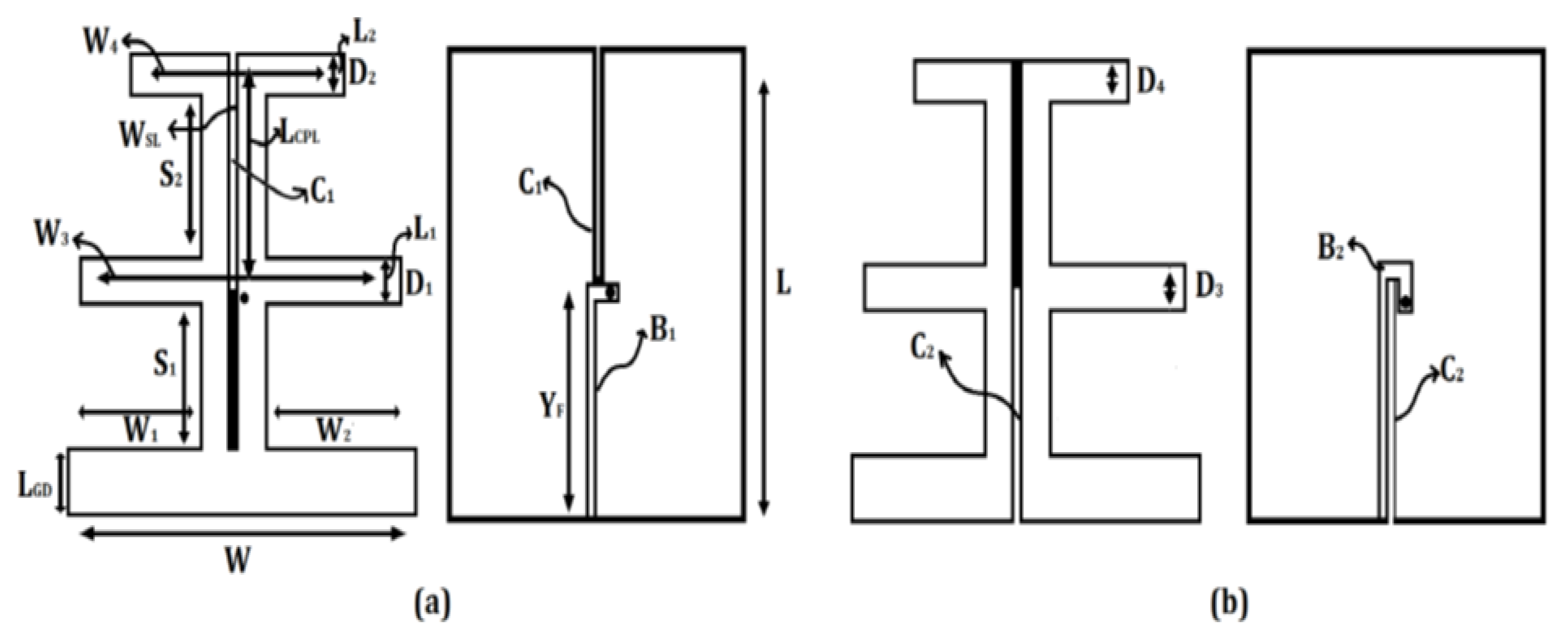
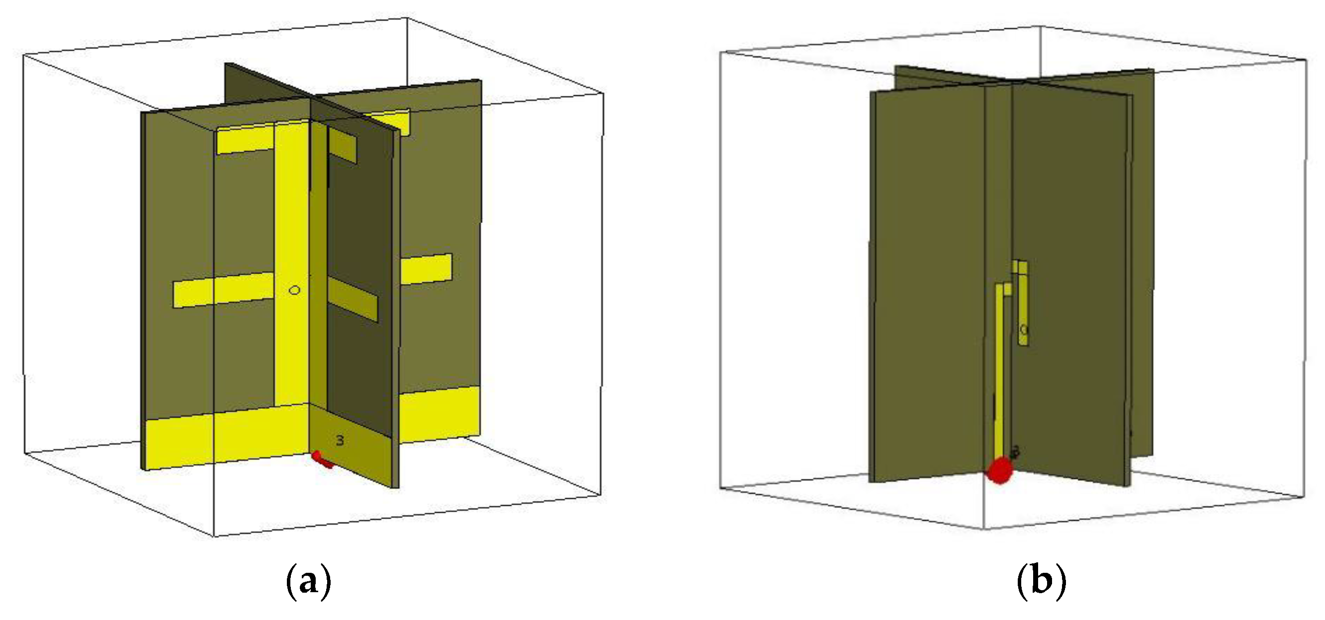
2. Antenna Design and Discussion

In this section, the design of the cross-dipole array antenna (orthogonal formation) is discussed. Two different baluns B1 and B2 are connected by SMA connectors. Figure 1a,b show the front and rear views of a dipole element antenna, baluns B1 and B2 are modified to match the impedance and a stub is added. Impedance matching is easily accomplished by moving the feed point inside the integrated balun. The cross-dipole element antenna is made by cutting the CPS C1 with a 1.6 mm width from the top to the length of 30 mm and again from the bottom to the height of 48 mm for C2, as shown in Figure 1a,b. The feeding position got analyzed for the reduction and maintenance of return loss, mutual coupling, and impedance matching. The total dimension of the proposed array antenna element is 66 × 66 × 78 mm3, and the structural parameter values of the proposed antenna are as follows: Width of the patch (W) = 66 mm, Length of the patch (L) = 78 mm, which consists of two dipole strips, two baluns, and two inverted L-shaped feeding strips, which are shown in Figure 1. The ground plane LGD has a 12 mm height. Dipole-1 D1 has dimensions of width W1 = 62 mm and length L1 = 6.4 mm. For dipole-2 of D2, similarly, W2 = 57 mm and L2 = 6.4 mm. The first dipole (D1) to ground plane distance (S1) = 29 mm; the first dipole (D1) to the second dipole (D2) distance (S2) = 28.6 mm. The cross-dipole array (formed from two orthogonal short-dipole antennas) antenna in a split arrangement is shown in Figure 2, and in the orthogonal arrangement in Figure 3. Figure 4 shows a model of the proposed antenna—with a different perspective view, it shows balun adjustment and orthogonal strip adjustment (with Figure 4a,b). A six cross- STDA antenna element is assembled to form an antenna array. Figure 5 shows the proposed antenna array configuration. In this configuration, L1 is the length of the antenna array, L2 is the length of the sidewall, and L3 is the spatial distance between two adjacent elements. The presented model has a rectangular reflector, six radiating elements, and two ladder sidewalls. The wavelength of the frequency and the distance between neighbouring elements are correlated. In order to prevent the appearance of a grating lobe, the space between elements is also kept closer than the operational wavelength of the operating frequency band. The operating frequency of the proposed antenna ranges from 3.2 to 5.22 GHz. The dimension of a single unit of the array is 66 × 66 × 78 mm3 and 642 mm × 112 mm × 90 mm is the overall dimension of the 1 × 6 array configuration and the proposed array element can be used for any configuration. Additionally, a metal box reflector with a side wall, having a dimension of 353.55 mm × 18 mm is used to obtain the high gain and stable radiation pattern as shown in Figure 5. A vector network analyzer was used to test the reflection coefficient of the prototyped antenna array. The simulation and experimental S11 and S22 parameters are shown in Figure 6. The operating frequency for the proposed design is 3.2 to 5.2 GHz with a wavelength of 93.6 mm to 57.4 mm, S11 and S22 parameters of both strips has been illustrated along with the reflector and sidewalls design in Figure 6. In addition to the simulation, Figure 6 illustrates the results of the experiment for the 3.2–5.22 GHz band with both strips placed perpendicularly (because there are two input ports, compared to a traditional square loop dipole), the cross-section area covered by the proposed design is less [12]. This indicates the reflection coefficients for both strips which is less than −15 dB for the resonating band. The structural parameters of the proposed antenna array are presented in Table 1.
A novel reflector with three different sidewalls has been studied for greater gain and better radiation efficiency. Figure 7 shows the side views of all three structures. (a—“ladder” sidewalls), (b—“U”-shaped sidewalls), and (c—“beveled edge” sidewalls). A comparative analysis has been conducted for the same dimensional reflector and the same distance between the reflector and the sidewalls. The CST simulation software was used to simulate the proposed antenna.
The distance between adjacent elements directly affects the antenna gain and mesh petals [13]. The array elements are placed to maintain good HPBW and are analyzed for different cases of without side walls and with different side walls. For the case, without the sidewalls, the designed array element generates the HPBW range of 53° to 69°. Ladder and beveled edge sidewalls produce good performance with different array configurations, and it has been found that the ladder and beveled edge sidewalls are adequate for the convergence and stability of HPBW. The HPBW range of 53° to 69° is achieved through simulation for the 1 × 6 array antenna without sidewalls, but, at the same time, 60° to 72° is achieved with ladder and beveled edge sidewalls as shown in Figure 8.
In addition, it’s not a general discussion of the XPD (cross-polar discrimination) at ±60° azimuth in literature [5,6,8,9], but it is a very essential component for existing BSA communication system. XPD at ±60 is analyzed for the different sidewalls in the all-operating frequency, which is better than the case without sidewalls. As illustrated in Figure 9, comparing the ladder sidewalls to U-shaped and beveled edge sidewalls, consistent and higher XPD values are discovered between 11 dB and 23 dB. These values can satisfy the communication need.
Figure 10 shows the changes in gain with different side walls. As observed, the ladder sidewalls produce stable and better gain performance compared to other sidewalls. It can be observed from the simulation results that for the suggested 1 × 6 array structure shows a gain variation in the range of 11 dB to 18 dB over the full frequency band with a ladder sidewall.
The radiation pattern for the array element is measured by the far-field test system. As shown in Figure 11, the suggested matrix for the 1 × 6 arrangement was simulated for the port-to-port isolation (S21) for various downward slope angles. It can be observed that port-to-port isolation is higher than 27 dB over the entire operating frequency band.

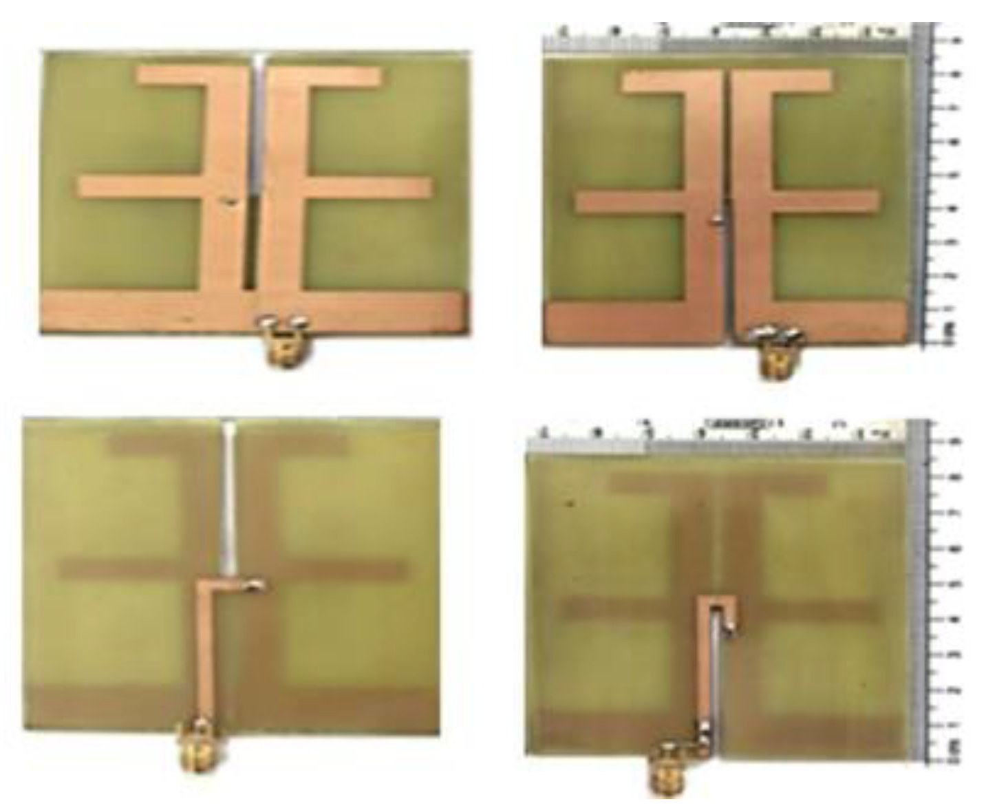
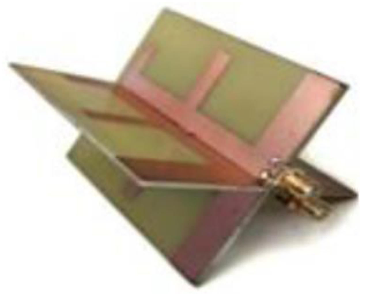
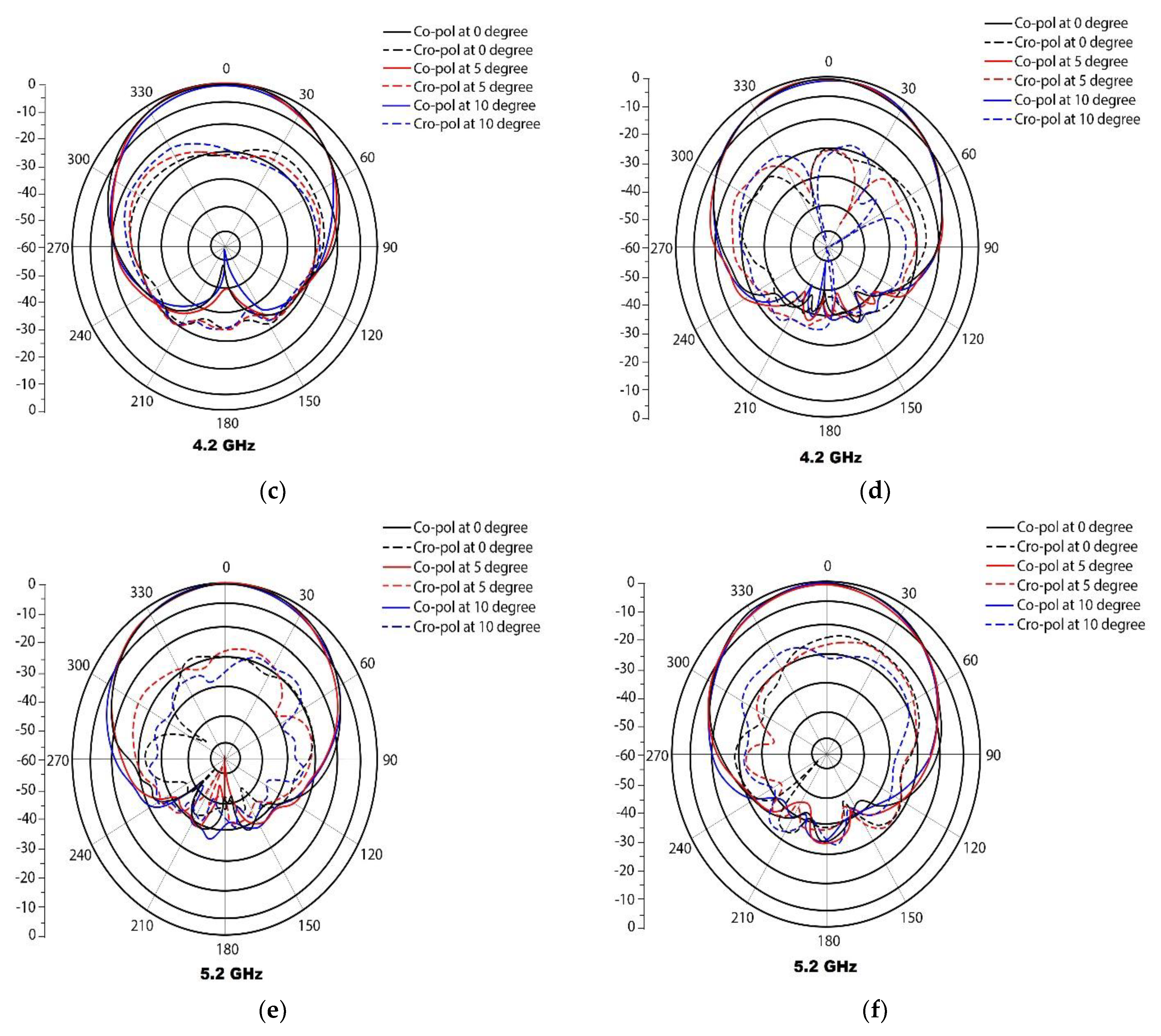
3. Measured Radiation Performance Analysis

The prototype of the proposed array element is fabricated and tested to analyze the radiation performance parameters. Both gain and HPBW are governed by the profile of the reflector sidewalls. The ladder sidewall is found more effective than the beveled and U-shaped sidewalls. 66 mm × 66 mm × 78 mm is the total dimension of the planned array antenna element. In an anechoic chamber, the network analyzer measures the port-to-port loss and the voltage standing wave ratio. The radiation pattern is evaluated by a far-field test device. The proposed design’s radiation pattern is also tested using the far-field test. The proposed array antenna has a symmetrical structure and the radiation patterns are measured for ports 1 and 2 at 3.2 GHz, 4.2 GHz and 5.2 GHz, respectively, for the broadside patterns in horizontal and vertical polarization. The simulated and measured radiation patterns at 3.2, 4.2, and 5.2 GHz are shown in Figure 12a–f. As shown in Figure 12, the co and cross-polarization are illustrated by a horizontal radiation pattern that is stable in the frequency band. A stable radiation pattern was maintained at various electrical downward tilt angles. It is important to emphasize the fact that at different electrical angles downward, the radiation patterns also remain coherent at the same time. In all operating frequency bands, the horizontal plane co-polarization radiation patterns are stable (65° ± 5°), and when the frequency band increases, the cross-polarization radiation patterns improve.
In addition, the various electrical down-tilt angles have been taken into consideration to account for the radiation pattern, and particular values, like gain, FBR, HPBW, and XPD (60°) in H-plane, are produced in accordance with the far-field test method. Table 2 shows the specific results of the radiation pattern. At 60-degree azimuths, high XPD (>11.5 dB) and FBR (>26 dB) resulted in the operating band with all considered down tilt angles. The radiation patterns at the horizontal plane remain stable as electrical downward tilt of the antenna beam increases.
The results from the far-field test equipment including HPBW, FBR, gain, and XPD (60°) in the H-plane are shown in Table 3. The multi-element antenna performance got compared with the proposed antenna array element for the bandwidth, H-plane, isolation, HPBW, FBR, gain, and the XPD (±60°). It is illustrated that 6 elements have excellent HPBW and FBR compared to the other configuration, where the XPD is not considered in the many kinds of literature. Evidently, all working bands and all down tilt angles produce a significant FBR (>26 dB) and high XPD (>11.5 dB) at 60° azimuths. As the electrical downward tilt angles of the antenna beam increase, the radiation patterns in the horizontal plane remain stable.

4. Conclusions

The proposed base station array antenna element is formed in 1 × 6 configuration along with a reflector and analyzed with three different sidewalls. Employing the 1 × 6 cross STDA array configuration and efficient side wall design for the reflector can produce a stable high gain performance in a band of 3.2–5.22 GHz. In addition, the various electrical downward-tilt angles have been considered for the radiation pattern, and particular values, like gain, FBR, HPBW, and XPD (60°) in the H-plane. Finally, measurement is performed for the cross-array element with the proposed reflector can obtain good radiation characteristics, like good reflection coefficient (<−15 dB), and high isolation between the ports (>31 dB). With this advantage, the proposed array element is a potential candidate for the diverse array system, which is suitable for the existing communication system.

Author Contributions

Conceptualization: M.W., S.K., P.K.M. and S.D.; Methodology: M.W., S.K., P.K.M. and S.V.K.; Formal analysis: S.V.K., W.E.-S., M.H.A. and S.D.; Investigation: M.W., S.K., P.K.M. and S.V.K.; Software: M.W., W.E.-S., S.V.K. and M.H.A.; Validation: M.H.A., M.W. and S.D.; writing—original draft preparation: M.W., S.K. and S.D.; writing—review, and editing: P.K.M., S.V.K., W.E.-S. and M.H.A.; supervision: S.K., P.K.M. and S.D.; Project administration: M.H.A. and W.E.-S.; Funding acquisition: W.E.-S. All authors have read and agreed to the published version of the manuscript.

Funding

This research received no external funding.

Data Availability Statement

The data presented in this research are available on request from the corresponding author.

Acknowledgments

The authors would like to acknowledge the support of Prince Sultan University for paying the Article Processing Charges (APC) of this publication.

Conflicts of Interest

The authors declare no conflict of interest.

References

  1. Thi, L.; Ha, C.; Ta, S.X.; Quyen, N.X.; Kiem, N.K.; Chien, D.-N. High-Isolation Wide-Beam Dual-Polarized Antenna Uti-lizing Symmetrical Feeding. Prog. Electromagn. Res. M 2022, 111, 53–63. [Google Scholar]
  2. Liao, C.; Wang, B.; Zhu, C.; Hao, H.; Yin, B. Broadband Dual-Polarized Loop Cross-Dipole Antenna for 5G Base Station Applications. Electronics 2020, 9, 1574. [Google Scholar] [CrossRef]
  3. Fan, J.; Lin, J.; Cai, J.; Qin, F. Ultra-wideband circularly polarized cavity-backed crossed-dipole antenna. Sci. Rep. 2022, 12, 4569. [Google Scholar] [CrossRef] [PubMed]
  4. Yang, Z.; Zhou, J.; Kang, L.; Liu, B.; Yang, G.; Shi, X. A Closed-Loop Cross-Dipole Antenna Array for Wideband OAM Communication. IEEE Antennas Wirel. Propag. Lett. 2020, 19, 2492–2496. [Google Scholar] [CrossRef]
  5. Li, M.; Chen, X.; Zhang, A.; Kishk, A.A. Dual-Polarized Broadband Base Station Antenna Backed With Dielectric Cavity for 5G Communications. IEEE Antennas Wirel. Propag. Lett. 2019, 18, 2051–2055. [Google Scholar] [CrossRef]
  6. Zhu, Y.; Chen, Y.; Yang, S. Integration of 5G Rectangular MIMO Antenna Array and GSM Antenna for Dual-Band Base Station Applications. IEEE Access 2020, 8, 63175–63187. [Google Scholar] [CrossRef]
  7. Huang, H.; Liu, Y.; Gong, S. A Dual-Broadband, Dual-Polarized Base Station Antenna for 2G/3G/4G Applications. IEEE Antennas Wirel. Propag. Lett. 2016, 16, 1111–1114. [Google Scholar] [CrossRef]
  8. Yang, J.; Ding, M.; Mao, G.; Lin, Z.; Zhang, D.-G.; Luan, T.H. Optimal Base Station Antenna Downtilt in Downlink Cellular Networks. IEEE Trans. Wirel. Commun. 2019, 18, 1779–1791. [Google Scholar] [CrossRef] [Green Version]
  9. Cui, Y.; Li, R.; Fu, H. A Broadband Dual-Polarized Planar Antenna for 2G/3G/LTE Base Stations. IEEE Trans. Antennas Propag. 2014, 62, 4836–4840. [Google Scholar] [CrossRef]
  10. Zheng, D.; Luo, Y.; Chu, Q.-X. A Miniaturized Wideband Dual-Polarized Antenna Based on Mode-Control Principle for Base-Station Applications. IEEE Access 2020, 8, 62218–62227. [Google Scholar] [CrossRef]
  11. Lian, R.; Wang, Z.; Yin, Y.; Wu, J.; Song, X. Design of a Low-Profile Dual-Polarized Stepped Slot Antenna Array for Base Station. IEEE Antennas Wirel. Propag. Lett. 2015, 15, 362–365. [Google Scholar] [CrossRef]
  12. Amer, R.; Saad, W.; Marchetti, N. Toward a connected sky: Performance of beamforming with down-tilted antennas for ground and uav user co-existence. IEEE Commun. Lett. 2019, 23, 1840–1844. [Google Scholar] [CrossRef] [Green Version]
  13. Chaudhuri, S.; Mishra, M.; Kshetrimayum, R.S.; Sonkar, R.K.; Bhattacharjee, S.; Saha, B. High port-to-port isolation dual circularly polarised microstrip patch antenna with multifunction DGS. IET Microwaves, Antennas Propag. 2020, 14, 2035–2044. [Google Scholar] [CrossRef]
  14. Gabriel, R.; Geissler, M. Antenna Systems for Cellular Base Stations. In Handbook of Antenna Technologies; Springer: Singapore, 2016; pp. 2271–2346. [Google Scholar] [CrossRef]
  15. Chataut, R.; Akl, R. Massive MIMO Systems for 5G and beyond Networks—Overview, Recent Trends, Challenges, and Future Research Direction. Sensors 2020, 20, 2753. [Google Scholar] [CrossRef] [PubMed]
  16. Wen, D.-L.; Zheng, D.-Z.; Chu, Q.-X. A Dual-polarized Planar Antenna Using Four Folded Dipoles and Its Array for Base Stations. IEEE Trans. Antennas Propag. 2016, 64, 5536–5542. [Google Scholar] [CrossRef]
  17. Luo, S.; Zhang, Y.; Pedersen, G.F.; Zhang, S. Mutual Decoupling for Massive MIMO Antenna Arrays by Using Triple-Layer Meta-Surface. IEEE Open J. Antennas Propag. 2022, 3, 1079–1089. [Google Scholar] [CrossRef]
  18. Nadeem, I.; Choi, D.-Y. Study on Mutual Coupling Reduction Technique for MIMO Antennas. IEEE Access 2018, 7, 563–586. [Google Scholar] [CrossRef]
  19. Chaudhuri, S.; Kshetrimayum, R.S.; Sonkar, R.K. High inter-port isolation dual circularly polarized slot antenna with split-ring resonator based novel metasurface. AEU-Int. J. Electron. Commun. 2019, 107, 146–156. [Google Scholar] [CrossRef]
  20. Chen, X.; Zhang, S.; Li, Q. A Review of Mutual Coupling in MIMO Systems. IEEE Access 2018, 6, 24706–24719. [Google Scholar] [CrossRef]
Figure 1. Front and back and separated view of the cross-dipole element antenna. (a) strip with top cut (b) strip with bottom cut.
Electronics 12 00669 g001
Figure 2. Cross STDA element for the different configuration array.
Electronics 12 00669 g002
Figure 3. Formation of cross STDA element.
Electronics 12 00669 g003
Figure 4. Model of the proposed antenna. (a) Dipoles in orthogonal formation View (b) Balun Feed View.
Electronics 12 00669 g004
Figure 5. The simulated 3D model antenna array of 1 × 6 array and reflector.
Electronics 12 00669 g005
Figure 6. Simulated and measured S-parameters (S11 and S22) of single array element.
Electronics 12 00669 g006
Figure 7. Analysis of the (a) ladder sidewalls (b) U-shaped sidewalls, and (c) beveled edge sidewall structures.
Electronics 12 00669 g007
Figure 8. The simulated HPBW with sidewalls and without sidewalls of the reflector.
Electronics 12 00669 g008
Figure 9. The simulated XPD (±60) with sidewalls and without sidewalls of reflector.
Electronics 12 00669 g009
Figure 10. 1 × 6 array antenna gain performance.
Electronics 12 00669 g010
Figure 11. Isolation between the ports.
Electronics 12 00669 g011
Figure 12. Simulated and measured H-plane radiation patterns of the proposed antenna array (a) Simulated at 3.2 GHz. (b) Measured at 3.2 GHz. (c) Simulated at 4.2 GHz. (d) Measured at 4.2 GHz. (e) Simulated at 5.2 GHz. (f) Measured at 5.2 GHz.
Electronics 12 00669 g012aElectronics 12 00669 g012b
Table 1. Design parameters for the cross-element STDA.
TermValue (mm)Term Value (mm)
L78L16.4
W66L26.4
S129LCPL36
S228.6Yf31
W127.36WFD3
W227.36LGD7.6
W357D162
Table 2. Specific results of the radiation pattern.
Down tiltFrequency (GHz)HPBW FBR (dB)Gain (dBi)XPD ± 60°
3.269.3526.6113.9215.87
4.264.4731.6714.2513.62
5.260.6533.3913.9814.54
3.29.8628.8913.9817.11
4.267.2133.7114.8712.17
5.260.3633.7116.1111.57
10°3.270.2333.4413.8915.21
4.267.5830.7114.714.23
5.261.231.261514.62
Table 3. Performance comparison of other reported Antennas with the proposed design.
Ref.Array ConfigurationSize (mm)Gain (dB)Bandwidth (GHz)Port to Port
Isolation
HPBW
H-Plane
XPD (±60°)Down Tilt
616-element344 × 3448.6 and 7.30.69–0.96 and 3.3–5.0>30 dB74° in LB and 88° in UB>25 dBElectrical
78-element880 × 112161.7–2.7>30 dB65 ± 8°NGNG
820-element45.2 × 45.28.7 ± 0.51.71–2.69>28 dB64.8 ± 2.7°7 dBElectrical
105-element640 × 24016.4 and 18.8704–960 and 1710–2690>27.5 dB61.5° and 90°22 dBElectrical
134-element69 × 6913.5 and 13.91.55–2.5 and 1.69–2.5>35 dBNGNGNG
Proposed6-element66 × 66 × 7811–18 dB 3.2–5.22>27 dB53°–69°11 dB–23 dBElectrical
NG = Not given.
Disclaimer/Publisher’s Note: The statements, opinions and data contained in all publications are solely those of the individual author(s) and contributor(s) and not of MDPI and/or the editor(s). MDPI and/or the editor(s) disclaim responsibility for any injury to people or property resulting from any ideas, methods, instructions or products referred to in the content.

