1. Introduction
In recent decades, due to its diversified applications, cooperative control, including consensus control [
1,
2], formation control [
3,
4], formation tracking control [
5,
6], obstacle avoidance control [
7], etc. has won widespread attention. Formation control has always been a hot research topic, and various classical control methods have been investigated and applied, such as leader–follower [
8], virtual structure [
9], and behavior [
10] based formation control methods. With the development of formation tracking control, the consensus based technique has caught researchers’ eyes. Since the basic framework for formation tacking control via consensus theories has been established [
11,
12], researchers are paying more attention to improving the performance of the formation tracking control, such as finite time convergence [
13], adaptive control [
14,
15], etc.
Recently, several formation tracking control protocols were established in [
16,
17,
18,
19]. Deng in [
16] investigated an adaptive time-varying formation tracking control based on an event-triggered strategy. However, the unknown input of the leader was not considered extensively. Since the followers and the leader could be non-cooperative, the unknown input of the leader is more general than the situation which all followers can achieve the leader’s state. Zhang in [
17] studied the heterogeneous multi-agent systems with an unknown input of the leader based on the distributed observer. For the multi-agent systems, collisions will occur during formation tracking inevitably, in order to realize the safety of the multi-agent system, it is necessary to take the collision and obstacles avoidance into consideration. Formation tracking problems were processed by using the distributed model predictive control (DMPC) method in [
18,
19] to deal with the collision avoidance and obstacle dodging problems simultaneously. The stability and the feasibility of the DMPC algorithm for time-invariant formation tracking with collision avoidance were proved theoretically. However, though these formation tracking control methods have been applied for years, it should be pointed out that there are great differences between practical experiment and theoretical analysis.
In the existing actual flight formation control for UAVs, although UAV can form the desired formation, it can not effectively specify and track the overall trajectory of UAV swarm. Furthermore, in practical applications, UAVs should be able to follow a specific trajectory or the states of real or virtual leaders as well as avoiding obstacles on the path [
20]. In order to solve the above problems, the concept of formation tracking is proposed. Most of the UAV formation flying experiments are time-invariant formations [
21,
22,
23], and the time-varying flight experiment of formation tracking is carried out in [
24,
25], where the follower UAV can form a time-varying formation to track the leader UAV, but the leader UAV is required to have no control input [
26]. However, in most practical application scenarios, the leader UAV needs to have external input to generate more reference trajectories. Yu studies the UAV system with unknown input in theory in [
27], but no actual flying experiment is conducted. Furthermore, it is common to have obstacles during flight, and the obstacle and collision avoidance of UAV in the flying experiment has not been studied extensively.
Motivated by the above analysis, this paper aims to investigate the TVFT problem for high-safe UAV swarm systems with external input, which can guarantee the distances of individuals into a suitable range and avoid obstacles during the formation dynamic process. Considering that leader UAV and follower UAVs are non-cooperative, the leader’s input information is unknown to all followers. A finite time convergent distributed observer is constructed by using the neighboring information to observe the leader’s position, and a TVFT control protocol is given. The stability of the control protocol is proved by a Lyapunov function. Tello UAV is a small four rotor UAV with high safety designed by DJI for the indoor flight, and an experimental platform including five Tello UAVs is introduced in the paper. A formation tracking experiment is carried out to verify the control protocol. Compared with previous studies, the contribution of this paper mainly has two aspects. Firstly, a UAV formation tracking control protocol which considers collision and obstacle avoidance with a leader’s unknown control input is presented. It is more general compared with [
28] inwhich not only the leader has no input, but also collision and obstacles avoidance can not be achieved. Secondly, a cooperative experimental platform based on Tello UAV and motion capture system is designed, and the flight experiment of Tello UAV formation tracking control is presented. The TVFT control protocol is verified on this platform compared with [
29], which only consists of theoretical simulation results. The effectiveness of the control protocol is further verified by flight experiments in this paper.
The rest of the paper is organized as follows:
Section 2 gives some basic concepts of graph theory and problem description.
Section 3 gives a finite time convergent distributed observer based on the neighboring information, and a formation tracking protocol then proves that the UAV swarm system can realize the formation tracking under the protocol.
Section 4 gives a numerical simulation and introduces an experimental platform based on motion capture system and Tello UAVs. The proposed control protocol is verified on the experimental platforms.
Section 5 concludes the paper.
2. Preliminaries and Problem Description
2.1. Basic Graph Theory
Let G = be a weighed directed graph with N nodes, where = denotes the set of nodes, represents the edge between two associated nodes i and j, = denotes the weighted adjacency matrix associated with G. stands for an edge of graph G, for the weighted adjacency matrix , if and only if , and , otherwise. For the node , the neighbor set of it can be described by . The degree matrix of G is represented by D = , where . Then, the Laplacian matrix of the graph G is given as . Furthermore, use a diagonal matrix to describe the communication relationship between the leader and followers, where if the ith follower can receive the leader’s information, otherwise . For the directed graph G, if there exists at least one node that has directed paths to all other nodes, then the graph G is said to have a spanning tree.
2.2. Problem Description
Considering a UAV swarm system consisting of
N UAVs and
M obstacles, a leader UAV is defined as a UAV which has no neighbors, otherwise it is defined as a follower UAV. For a swarm system of UAVs, suppose the first UAV as the leader UAV labeled by 0, and the rest of the UAVs as the follower UAVs. All UAVs gather
, the follower UAVs gather
and the obstacles gather
. For any UAV
i in the swarm system, it can be regarded as a node
in the graph
G, and the communication between UAV
i and
j stands for the edge
in graph
G. Then, the TVFT can be carried out by using the two-time-scale separation principle [
30].
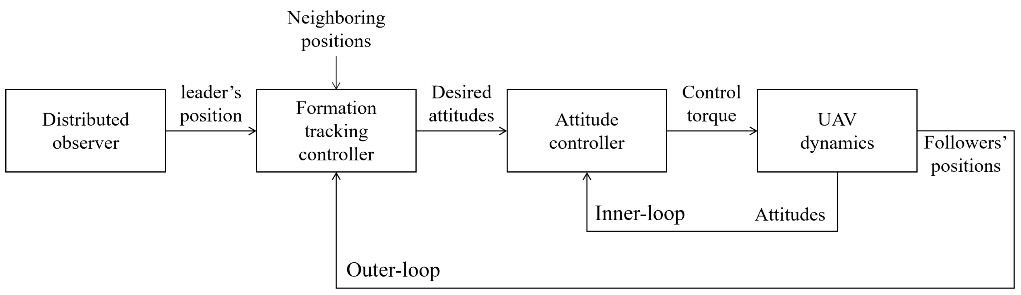
Figure 1 shows the control scheme for the two-loop formation tracking structure. For each of the UAVs, since the trajectory dynamics have much larger time constants than the attitude dynamics, the formation control can be decoupled into an inner-loop control and an outer-loop control, where the inner-loop controller stabilizes the attitude, and the outer-loop controller is used to drive the UAV towards the desired formation [
31]. Since the algorithm is a distributed architecture and not all followers can communicate with the leader, the formation tracking controller only needs the leader’s information obtained by the observer and neighbor nodes’ information.
Definition 1. The UAV swarm system is divided into the leader and follower depending on whether there is a neighbor. The leader UAV is the agent without neighbor UAVs and the follower has neighbor UAVs. Note that only a subset of followers can obtain the position of the leader directly, while other followers only require the neighbors’ states.
Assumption 1. The trajectory of the leader UAV is ideal under , that is, no problems of collision avoidance and obstacle dodging.
Assumption 2. The directed graph G of the UAV swarm has a spanning tree, and the root node is the leader UAV.
Assumption 3. In the process of UAV formation tracking, the collision mainly occurs in the formation process. When a stable formation is formed, a certain relative distance is maintained between UAVs, so it is supposed that the duration of collision avoidance is finite, and the obstacle avoidance exists in the formation process.
According to the composition properties of the swarm systems, the Laplacian matrix
can be expressed as
where
and
, and the eigenvalues of
are recorded as
.
Lemma 1 ([
32])
. All eigenvalues of have positive real parts. Lemma 2 ([
33])
. Under Assumption 2, there exists a positive matrix generated from , where equals the reciprocal of the ith component of , such that is symmetric and positive definite. For each UAV in the swarm system, the dynamics of attitude have a much smaller time constant than the trajectory, so the control period of outer loop is much longer than that of the inner loop. In this paper, only the formation tracking control problem is considered, and the attitude stability control problem is not considered. The kinematic model of UAV is considered as a first-order system that can be described by [
34]:
where
represents the position of the follower UAV
i, and
represents the control input.
The kinematic model of the leader UAV is also considered as a first-order system that is described by
where
represents the position of the leader UAV, and
represents the control input. The nonzero vector
is unknown to all the followers, which is a more general situation than
in [
35].
The , which stands for the unknown input of the leader UAV, is bounded and satisfies , where is a positive constant.
Definition 2. For any given bounded initial positions, if the following formula holds: represents the time-varying formation for the follower i; then, it can be defined that the specified time-varying formation tracking is accomplished by the UAV swarm systems. Definition 3. For any moment in the process of UAV formation tracking, if there exist positive constants and , satisfying that:where represents the position of obstacle k. Then, it can be defined that UAVs realize collision and obstacle avoidance in the formation tracking process. The purpose of this paper is to design a time-varying formation tracking control protocols with unknown control input of the leader UAV, collision avoidance, and obstacle avoidance, and then give the application of the control protocols on Tello-Motion Capture experiment platform.
3. Theoretical Analysis
In the following section, the algorithm and analysis of the formation tracking problems are put forward. Since the process of collision avoidance is unpredictable, the protocol with safety precautions is presented, and the stability of the closed-loop system is proved.
In order to maintain the safety distance, the potential functions are put forward to realize obstacle avoidance.
is used to represent the potential field function between UAVs to avoid the collision among UAVs,
is used to represent the potential field function between UAV and static obstacle to avoid collision between UAV and obstacles, which are defined as follows:
stands for the relative distance between follower UAVs,
stands for the relative distance between follower UAV and the obstacle.
and
represent repulsive constants,
,
represent the position of UAV
i,
j,
represents the position of obstacle
k:
Since not all followers can get the information of the leader’s position, it is necessary to design the distributed observer to observe the leader’s position. The distributed observer for the leader is given as:
where
represents the estimate of the leader’s position by follower
i,
and
.
Consider the following formation tracking protocol for the follower UAV
i:
where
K is the positive gain constant,
are the artificial potential field function determined by the position of UAV
i and
j and the artificial potential field function determined by the position of UAV
i and the position of obstacle
k,
is a positive constant satisfy
, and
is constructed to compensate the unknown input of the leader.
Lemma 3 ([
36])
. The distributed observer can realize a fixed-time consensus with the position of the leader under Assumptions 1–2 and the proposed protocol (8) with satisfying:where , and a settling time estimate is given by:where and , in which denotes the maximum component of γ in Lemma 2. It can be concluded that the error of the leader’s observer is convergent, which means .
Theorem 1. Suppose that Assumptions 1–3 hold. The UAV swarm system (2) with the unknown leader’s input achieves TVFT as well as collision and obstacle avoidance under the protocol (9).
Proof. Let
represent the formation tracking error of the
ith follower and then
. Consider the following Lyapunov function candidate:
Then, the derivative with respect to time of
V is expressed as:
Notice that
and
; then, the Equation (
14) can be simplified to:
Bring
and (9) into (15):
It should be pointed out that, during the UAV formation tracking, the collision mainly occurs in the formation dynamic process. When a stable formation is formed, a certain relative distance is maintained between UAVs to avoid collision and obstacles, which means
and
. Thus, the duration of collision avoidance is finite and the obstacle exists in the formation process. Define
as the end time of collision avoidance,
as the end time of obstacle avoidance and let
. When
, the observations
are considered equal to the leader’s position
, then the Lyapunov function can be simplified to:
Notice that
; then,
According to
, then:
Bring (20) and (21) to Equation (
18), then it follows that
When , the individuals are not subjected to the forces, namely and . It can be concluded that . By the definition, one has . This completes the proof. □
Remark 1. Because the nonlinear function designed in the protocol (9) is discontinuous, the designed time-varying formation tracking protocol (9) will cause the chattering of the control input . Then, we will replace it with a continuous function , where ϵ is a small positive constant. For example, we choose in the following experiment. As shown in [3], the TVFT errors will be uniformly ultimately bounded under this continuous function. Remark 2. Since uncertainties exist in the actual experiment, the kinematic model of UAV can be described by , where stands for the uncertainties of the input of the follower UAV i which has an upper bound δ that satisfies ; then, parameter ϕ in Equation (10) needs to be adjusted to which satisfies ; then, the unknown input disturbance of the follower can be suppressed. 4. Numerical and Experimental Results
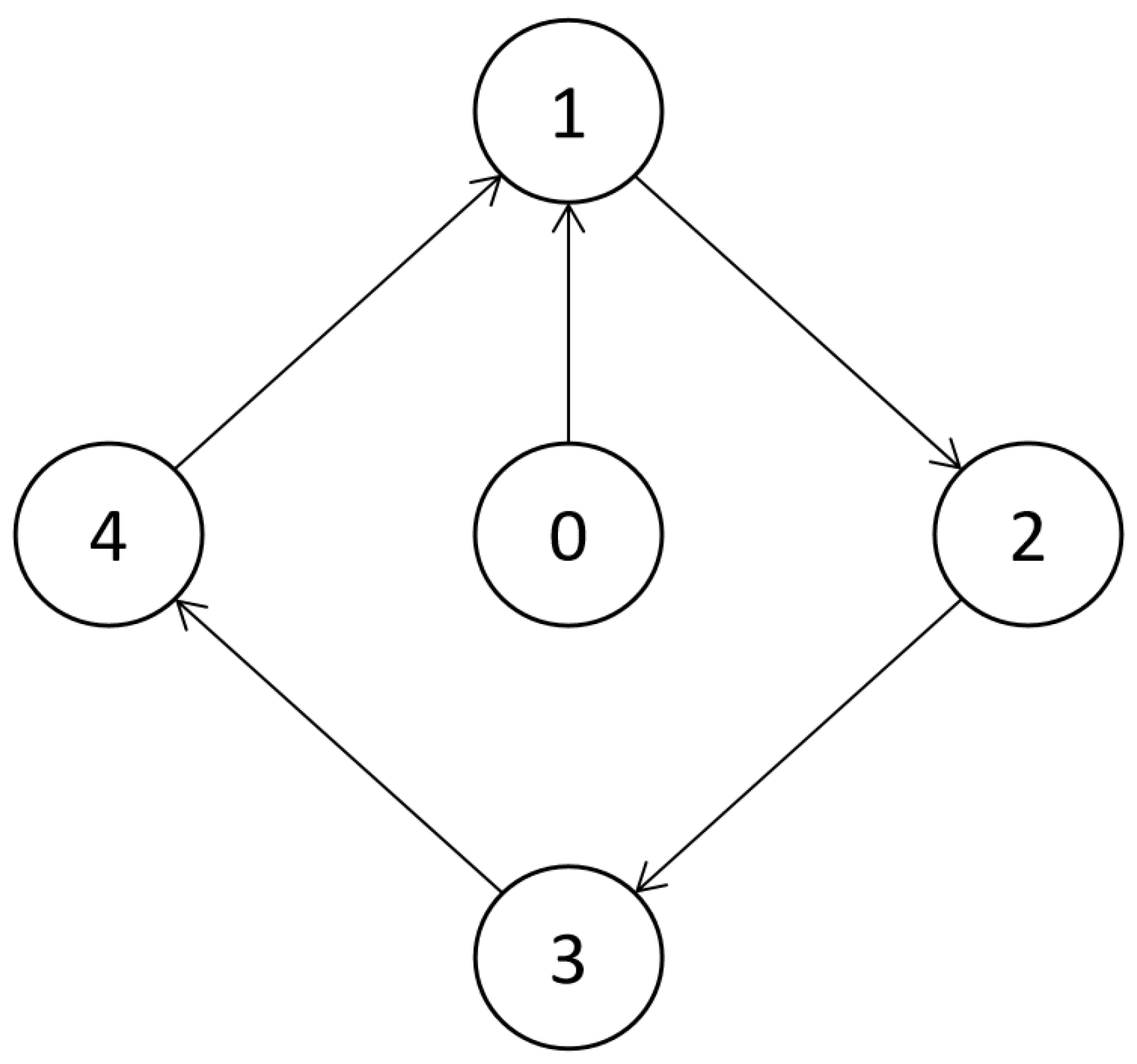
In this section, a numerical simulation applied in Matlab is given. Consider a UAV swarm system consisting of five UAVs, where the leader UAV is denoted by
, and the follower UAVs are denoted by
. The interaction topology of the UAV swarm system in the simulation is shown by
Figure 2, and the interaction weights are assumed to be 0 or 1.
The kinematic model of each UAV is described by:
. The outer-loops for trajectory dynamics along the
x-axis and
y-axis are controlled by the formation controller (9), and the height and the yaw angle of each quadrotor are specified to be constants. The desired formation vector is designed as
, where
and
, that is, the follower UAVs are expected to form a rotating circular formation while tracking the leader UAV which is more common than [
21,
22,
23], which cannot realize the time-varying formation tracking. The formation controller runs at 100 Hz. The gain constants
,
, the potential field function parameter
,
m,
,
m. According to the obstacle avoidance controller (10), UAVs can maintain a safe relative distance, and obstacles in the formation process will also be avoided. Thus, the safety of UAV system can be guaranteed compared with [
24], which cannot realize the obstacle avoidance. The unknown control input of the leader is set to be
. In practical applications, it is common that the input of leaders is not known, so it is more general to consider unknown input compared with [
24,
25,
26], which cannot track the leader with unknown input. The parameters of the observer are set to
,
.
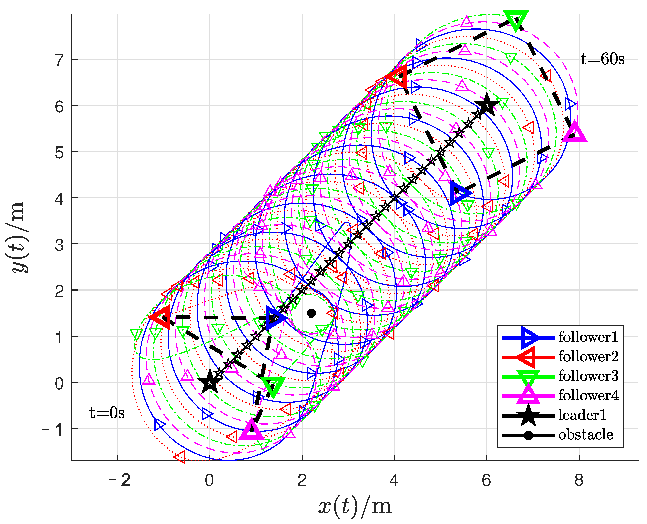
The position trajectory of UAVs is shown in
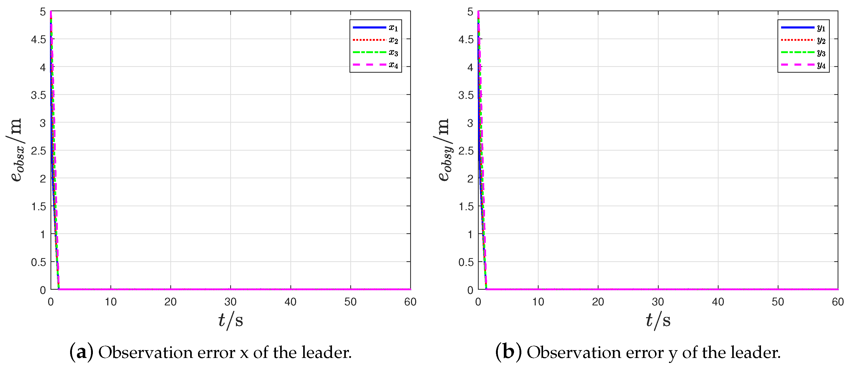
Figure 3, where the black pentagram symbol stands for the leader, and the other triangle symbols represent the followers; the black dot is used to indicate the obstacle. The curves of the observation errors are given in
Figure 4 and
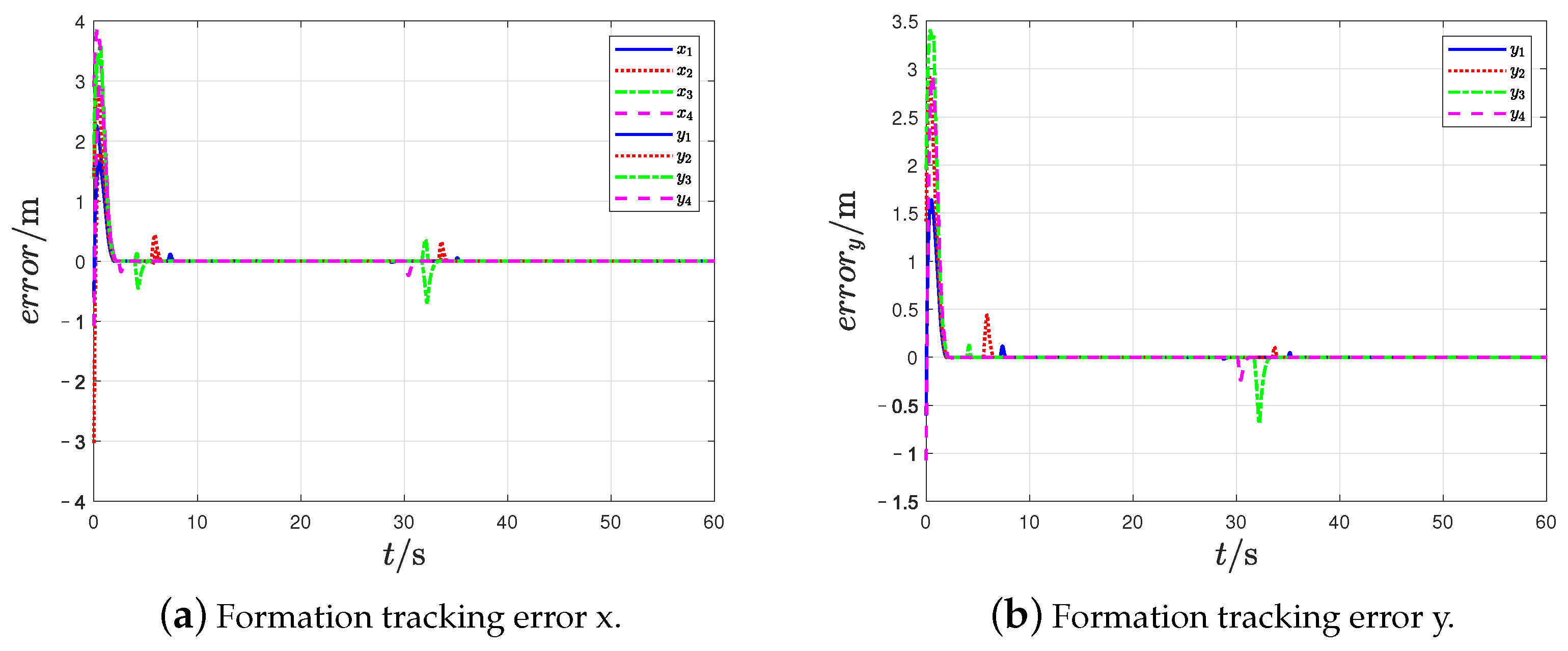
Figure 5, and the curves of the formation tracking errors are given in
Figure 6 and
Figure 7.
From
Figure 3, it can be found out that the followers form the given time-varying square formation while tracking the leader UAV and avoiding obstacles and collision.
Figure 4 indicates that the observation errors of the leader’s position can approach 0.
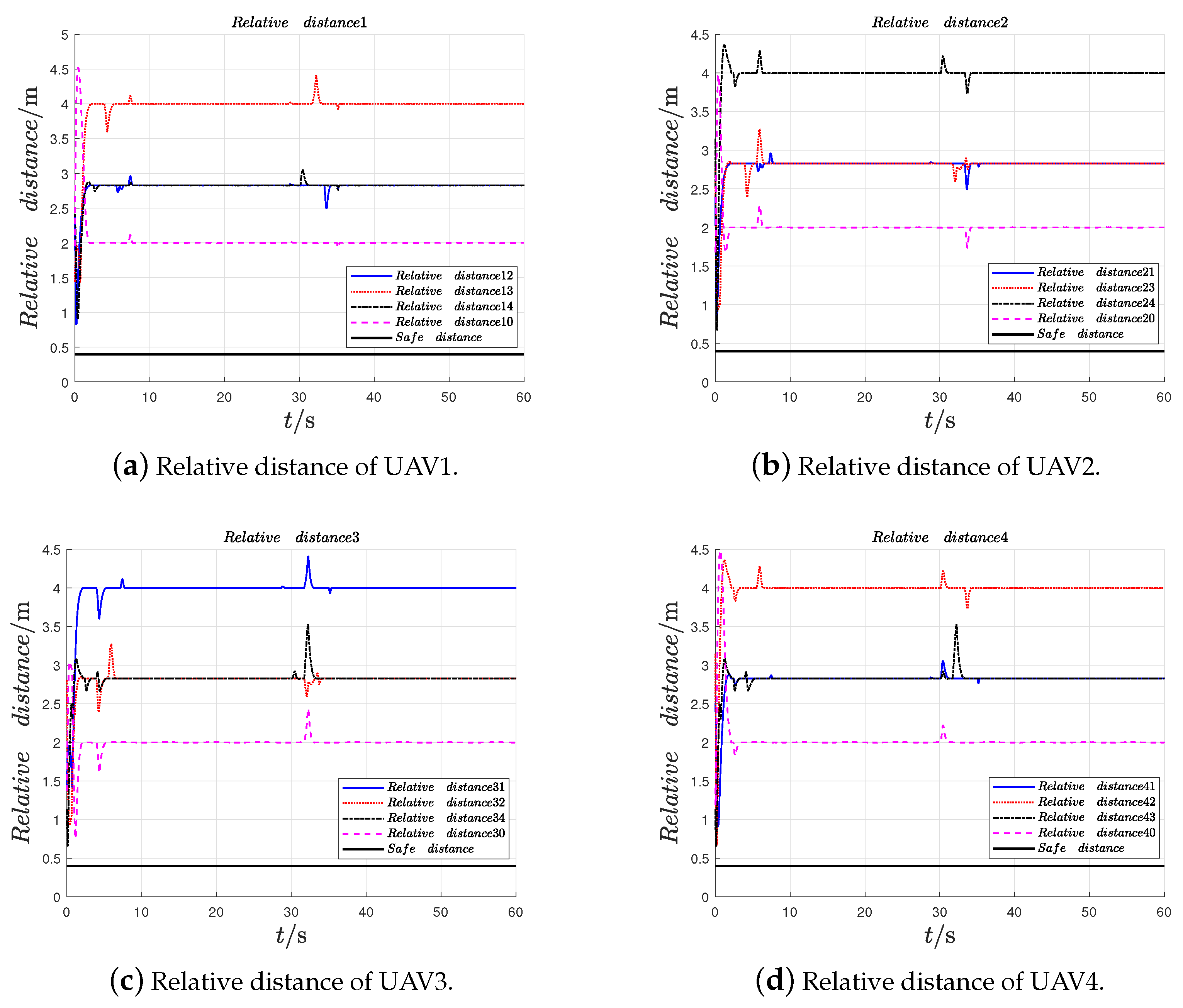
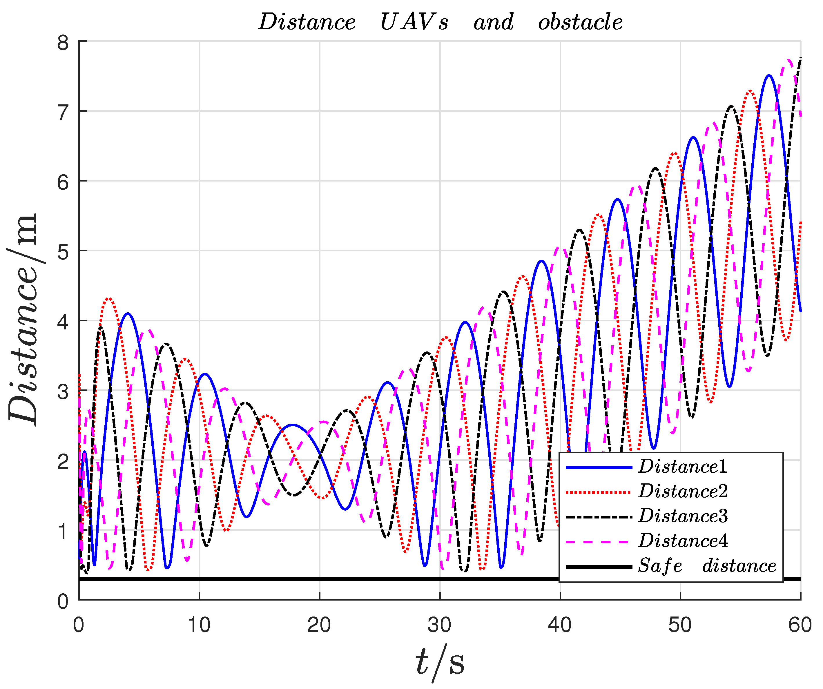
Figure 5 indicates that the formation tracking errors approach 0. The relative distances between the follower UAVs are shown in
Figure 6, and the safe distances between UAVs are set as
m. The relative distances between the follower UAVs and obstacle are shown in
Figure 7, and the safe distances between UAVs and obstacles are set as
m. The quadrotor UAV system performs the formation tracking task in the horizontal XY plane. Therefore, the formation tracking is realized by the UAV swarm system under the protocols (9).
Then, an experimental platform composed of Tello UAVs and the motion capture system is introduced. The effectiveness of the proposed formation tracking method is verified on this platform, and the results are drawn in the figures.
Figure 8 shows the hardware equipment diagram of the experimental system. The motion capture system captures the position of the Tello UAV and transmits it to the ground station via Wifi; then, the Tello UAV can get its neighboring position via Wifi and tracking the leader UAV.
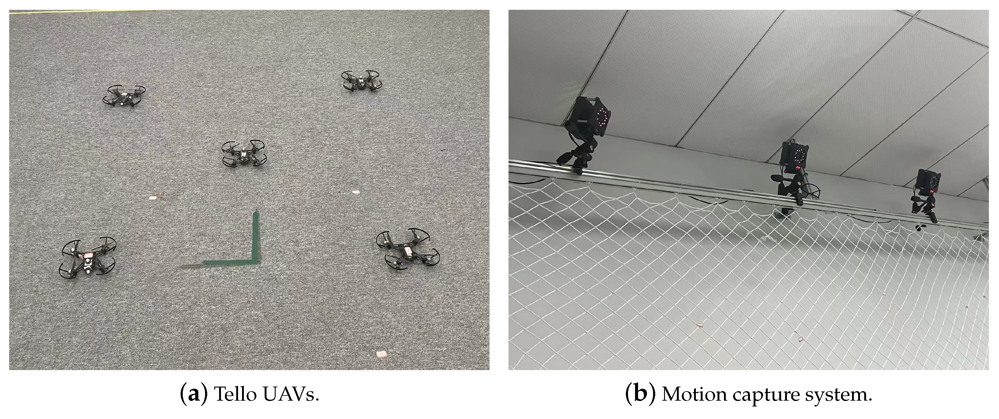
The main components of the experimental platform are shown in
Figure 9, which include five Tello UAVs and the motion capture system. Each Tello quadrotor has an 80 g ground weight with 6-cm tip-to-tip wingspan. The flight time of it is about 6–8 min. Because our algorithm is distributed, we need to use the relative distance of UAV rather than global information. The motion capture system provides the relative distance between UAVs by using optical cameras and subtracting the positions of the two drones. Each drone carries four marker balls to make sure that it can be captured by optical cameras. At the same time, the motion capture system calculates the position of the drone and transmits the results to the ground station. The outer loop for the trajectory in the XY plane is controlled by the formation tracking controller (9) at a frequency of 100 Hz.
We design the experiment with five Tello quadrotor UAVs and set the the radius parameter
m and
rad/s due to the flying space. From the expression of
, one can see that the formation is time-varying. The communication topology is the same as the simulation in
Figure 2, and the parameters of the controller are
,
,
,
m,
m,
m. The parameters of the observer are set to
,
. The video of the experiment can be achieved on
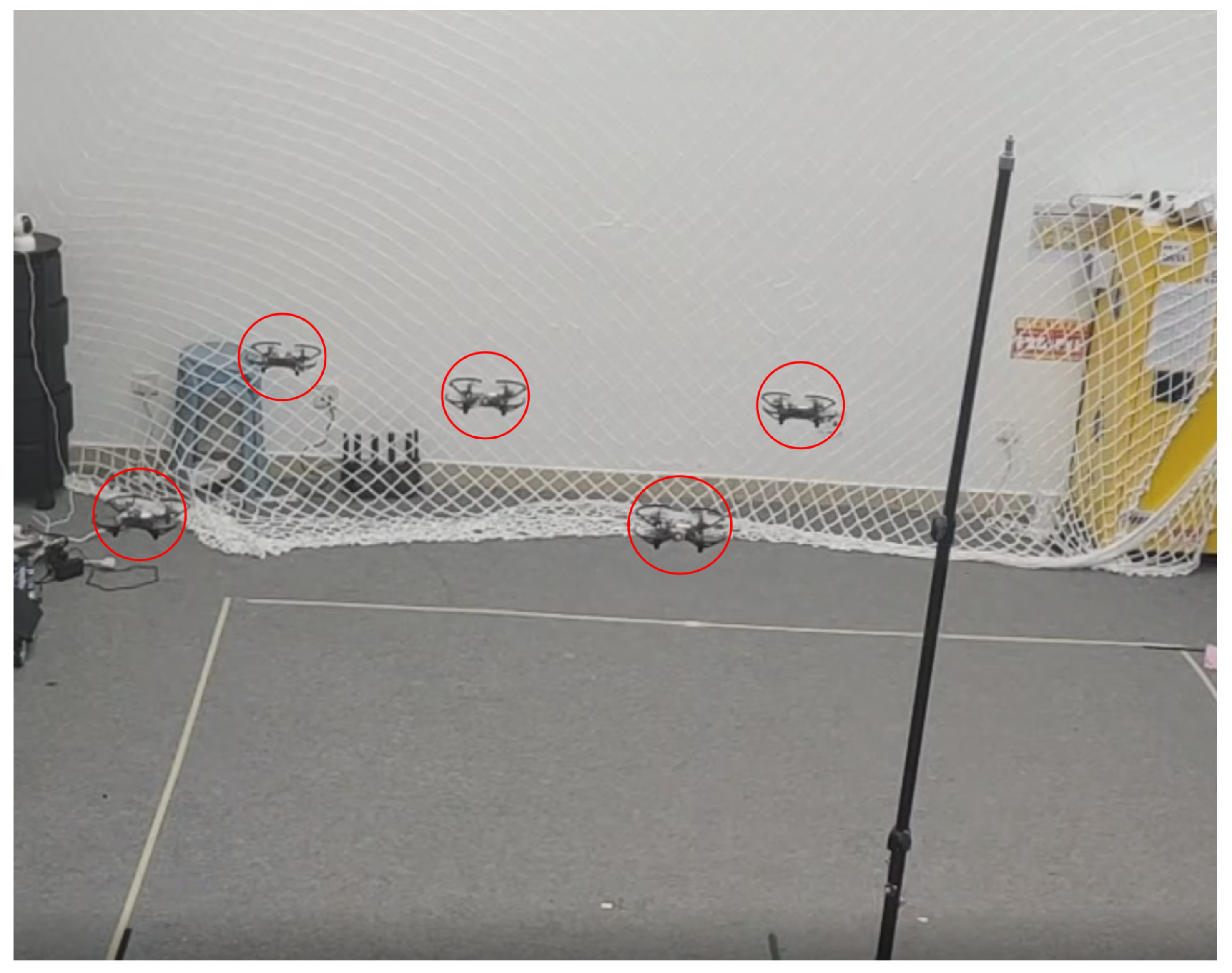
https://v.youku.com/v_show/id_XNTg2NzI2MzIyNA==.html (accessed on 2 May 2022), and a video clip of UAV formation tracking is shown in
Figure 10. The follower UAVs form a square formation while tracking the leader UAV in the center.
The results of the experiment are as follows:
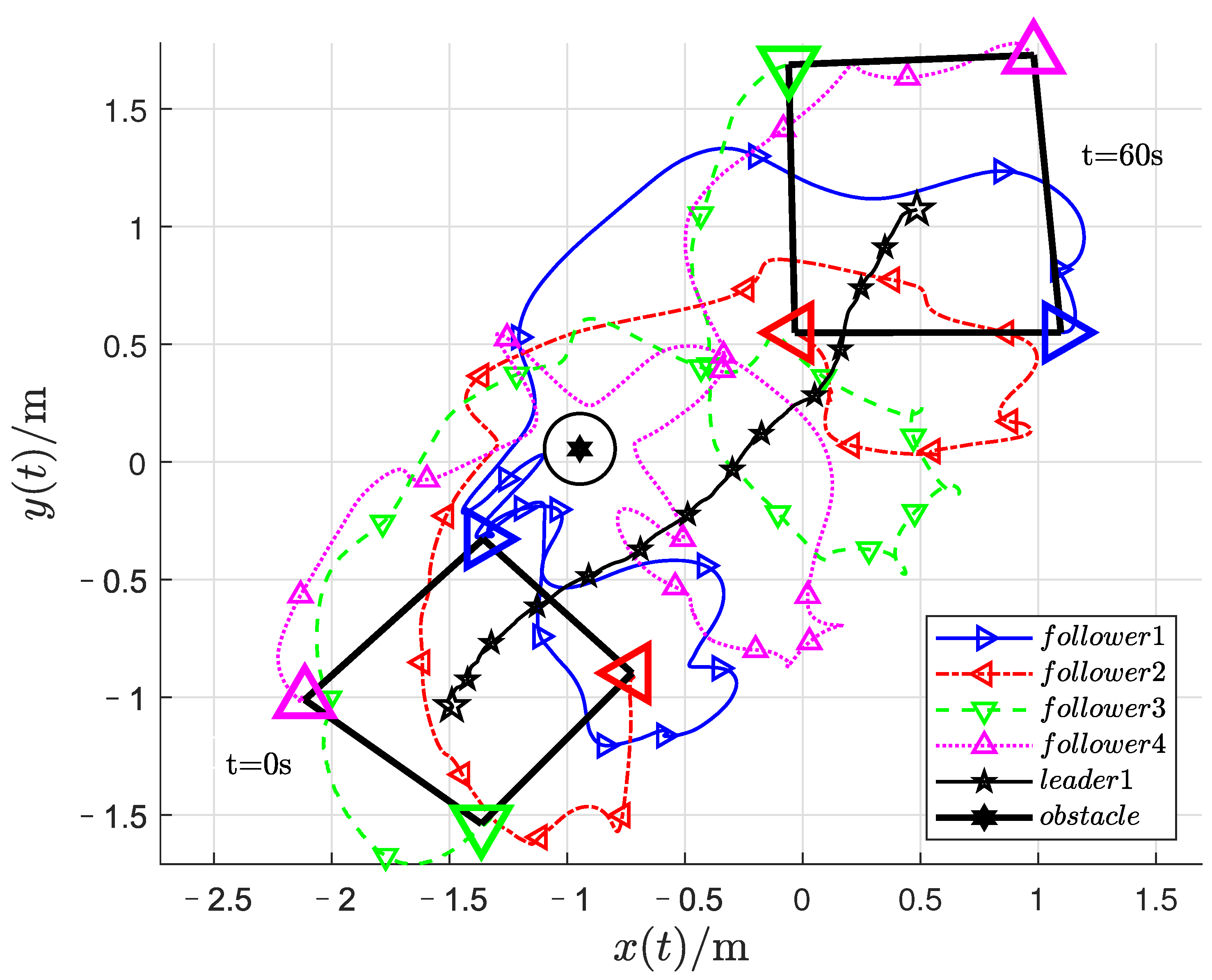
Figure 11 stands for the position trajectories of UAVs. As shown in
Figure 11, the black pentagram stands for the leader, pink, blue, red, and green triangles stand for the follower, the black hexagon represents the obstacle, and the circle around the obstacle represents the safe distance of the obstacle. For the follower UAVs with random initial positions at
s, only the follower 1 can estimate the position of the leader UAV, but all followers’ trajectories were adjusted when they approached the obstacle at position
. After the UAV swarm system completes the avoidance of obstacles, it forms a time-varying rectangular formation to follow the leader.
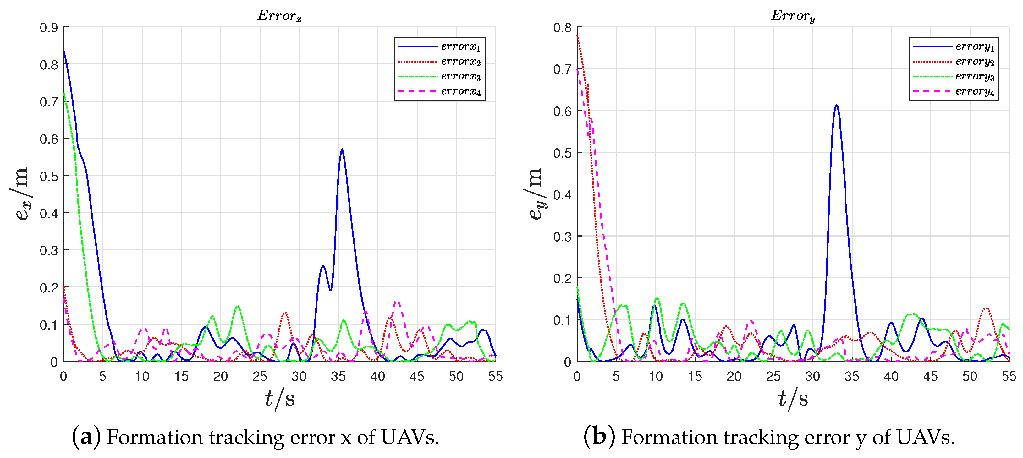
Figure 12 indicates that the formation tracking errors of the followers, as the swarm system completes the avoidance of obstacles, the formation tracking errors are uniformly ultimately bounded. The follower UAVs form the expected rotating square formation while tracking the leader UAV.
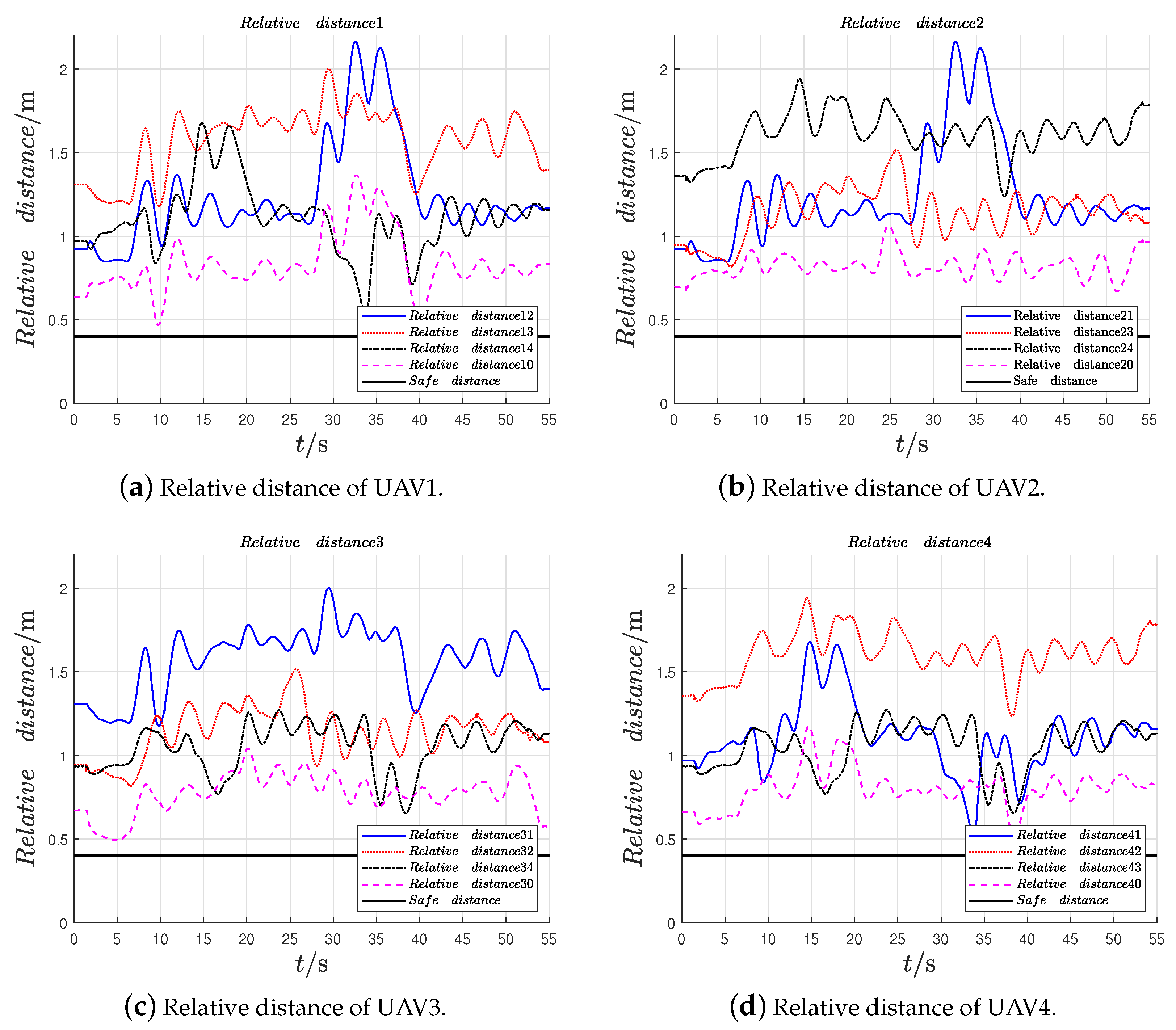
Figure 13 shows the relative distances between UAVs; we set the safe distance between UAVs as
m due to the size of Tello UAV, if the relative distance between any two UAVs is less than the safe distance, they are thought to have collided. It can be seen that the relative distance between UAVs is greater than the set safety distance
m of UAVs during the whole process of formation tracking.
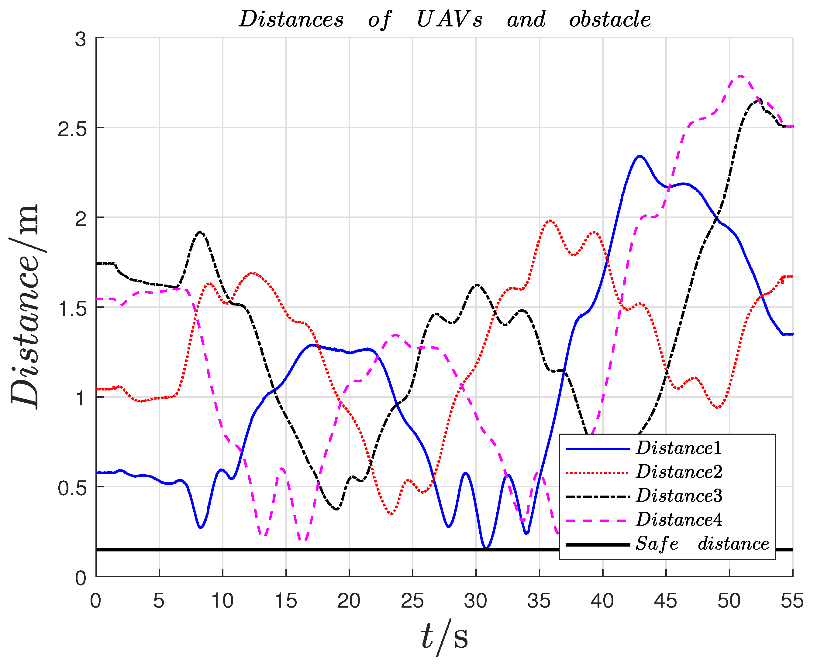
Figure 14 shows the relative distances between UAVs and obstacles, which indicates that the distances between UAVs and obstacle are greater than the set safety distance
m of UAVs. Therefore, the proposed collision and obstacle avoidance control approach are effective under the verification of the platform. Therefore, the preassigned TVFT using the proposed method is realized by the UAV swarm system in both the simulation and experiment.


