Article

Performance Analysis of PI and DMRAC Algorithm in Buck–Boost Converter for Voltage Tracking in Electric Vehicle Using Simulation

by
Maidul Islam
1,
Alia Farhana Abdul Ghaffar
1,*,
Erwin Sulaeman
1,
Md Manjurul Ahsan
2,
Abbas Z. Kouzani
3 and
M. A. Parvez Mahmud
3
1
Department of Mechanical Engineering, International Islamic University Malaysia, Gombak, Kuala Lumpur 53100, Malaysia
2
School of Industrial & Systems Engineering, University of Oklahoma, Norman, OK 73019, USA
3
School of Engineering, Deakin University, Geelong, VIC 3216, Australia
*
Author to whom correspondence should be addressed.
Electronics 2021, 10(20), 2516; https://doi.org/10.3390/electronics10202516
Submission received: 10 September 2021 / Revised: 7 October 2021 / Accepted: 9 October 2021 / Published: 15 October 2021

Abstract

:
This study introduces a Direct Model Reference Adaptive Control (DMRAC) algorithm in a buck–boost converter in the power distribution of an electric vehicle. In this study, DMRAC was used in order to overcome the system nonlinearity due to load demand variation, in case of different driving modes (such as acceleration, stable and regenerative braking system mode), and the presence of disturbances in the system. DMRAC receives popularity because of its robustness in the presence of nonlinearity and ensuring system stability. To evaluate the efficacy of DMRAC in the current system, its performance was compared with a PI controller in the MATLAB/Simulink environment. The simulation results show the superiority of DMRAC over a conventional PI control approach, in both variable load demand and disturbed system cases that were measured by tracking error. The improvement was seen in the DMRAC response, with smaller tracking error and faster transient and disturbance rejection. The main contribution of this work is in introducing DMRAC, particularly in a buck–boost converter, and its efficacy with a DC–DC converter for an electric vehicle, which has not been studied before.

1. Introduction

Electric-powered equipment has received a great deal of interest among researchers as an alternative to fossil fuel. Since electricity can be generated from various renewable sources and is environment friendly, policy makers nowadays are highly interested in bringing changes to sources of energy for transportation and industry. Higher fuel economy, lower emissions and better performance are the key factors that motivate researchers to pay more attention to the development of electric-powered vehicles as an alternative to internal combustion engines [1,2,3,4].
DC–DC converters are commonly used to charge and discharge the battery of an electric vehicle. The main characteristics of the converters that draw the attention of researchers are that they provide either higher or lower amplitude in output than the input [5], they are compact in size and they are cheap in price [6]. Basically, there are three topologies of DC–DC converters, such as buck, boost and buck–boost, where buck–boost can offer the functionalities of both buck and boost converters. Hence, in such a case, a model-based control approach can be considered as a suitable approach, where robust and adaptive control approaches have become popular among researchers for the last several decades [7].
In general, the conventional proportional–integral–derivative (PID) or proportional–integral (PI)-type control approaches are very widespread in industries, since they are simple to design and cheap in price [5]. These controllers cannot ensure robustness in a wide range of operating points, since they work on linearized models [7,8,9]. Hence, nonlinear controllers have been introduced to deal with the robustness, as the linear controllers are found to be inaccurate in the presence of disturbances to the system [10].
Among nonlinear-type controllers, Sliding Mode Control (SMC) has gathered popularity in the control of power converters, because of its ability to deal with model uncertainty [11], structural simplicity [7] and discontinuous switching signal control [12]. Despite several successful achievements from SMC in power converters [13,14,15], several drawbacks can be highlighted such as chattering [16,17], variable switching frequency that leads to electromagnetic interference [18] and, sometimes, steady-state errors at the output [19]. Feedback linearization and backstepping are two nonlinear control approaches that can be considered as a better solution to overcome the chattering problem and steady-state error. However, in feedback linearization, generally, a precise linear model is designed and often useful nonlinear features are removed from the system [20]. Despite some works with backstepping controllers with DC–DC converters [21,22], the backstepping controller requires a systematic framework to design. Additionally, to be able to reject uncertainties, it requires exact knowledge of the system parameters at any certain point of time, which is sometimes unavailable. Hence, backstepping is also sometimes not a suitable choice for researchers [7].
Adaptive control algorithms have gained popularity in power electronics, though they have just emerged in aerospace industry for the first time. A type of adaptive control, Model Reference Adaptive Control (MRAC), has several applications in power converters. This controller considers a pre-designed model, a reference model to define the required dynamics of the system, and follows an adaptation process [23]. It has achieved interest among researchers, as the performance of the system can be pre-defined through a reference model.
The literature introduces multifarious applications of MRAC in power electronics [24]. We chose a Direct MRAC in order to control the voltage input to a DC–DC boost converter with the help of a PI controller. In this study, we achieved a stable response and short period of settling time, rise time and overshoot during operation [25]. We chose MRAC for single-phase shunt active power with a view to reducing line current harmonics and improving line power factor. The choice to utilize MRAC was based on its adaptability, flexibility and robustness that surpasses PI controllers, and its self-tuning features that ensure stability of the system [26]. We applied a fractional order MRAC on a system that accommodated two power sources: a zero voltage switch full-bridge isolated DC–DC buck converter; and a resistive load so that the controller can stabilize the current and voltage of a DC–DC converter that is coupled with the DC bus link. The proposed controller surprisingly offers a fast dynamic response to DC bus voltage, and robustness to voltage variation in both load and input. This work proposes an adaptive controller in a buck–boost converter to control the voltage demand, according to motor demand. The novelty of this work is in the use of an adaptive controller, specifically a Direct Model Reference Adaptive Control (DMRAC) with a buck–boost converter for an electric vehicle’s power demand control, which previously has not been considered. Apart from that, this study showed the performances of two controllers, namely PI and DMRAC, and compared their performances based on a performance index, tracking error in both consistent load demand and variation in load demand in the presence of disturbances. Section 2 focuses on the topology of a buck–boost converter, and Section 3 deals with controller design. Subsequently, Section 4 highlights the simulation results and the controllers’ performances, based on the performance index. Finally, Section 5 outlines an exhaustive conclusion based on the results.

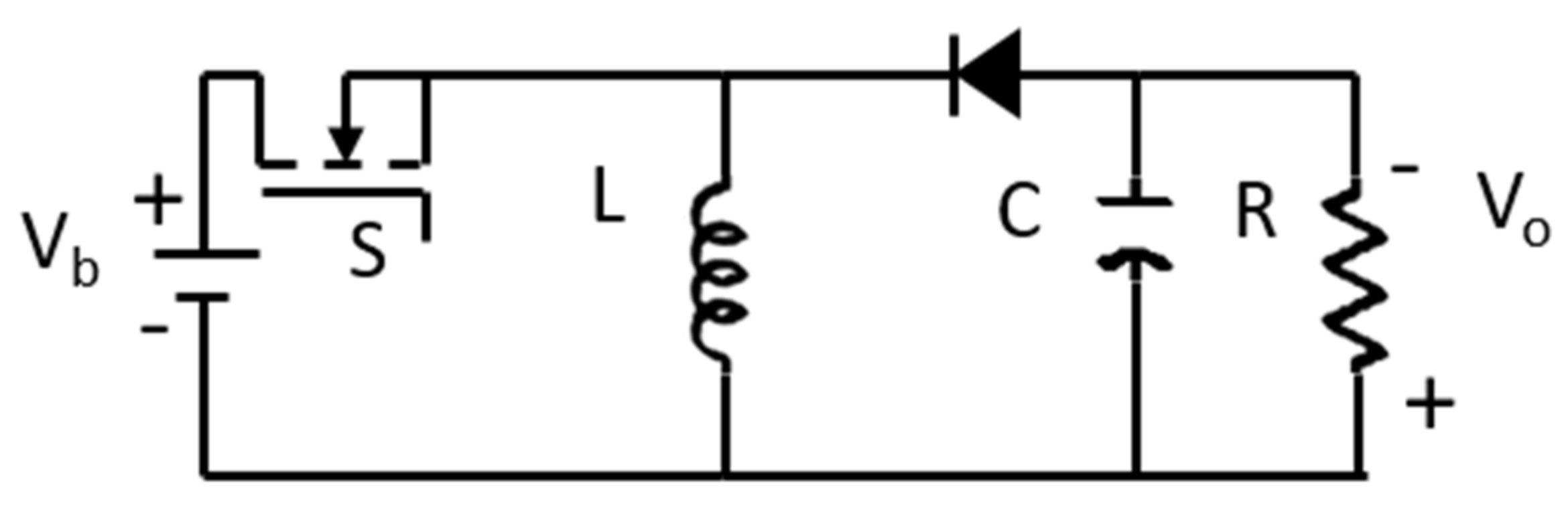
2. Modelling of a Buck–Boost Converter

A buck–boost converter is also familiar as a Bidirectional DC–DC Converter (BDC) since it steps up and steps down the voltage continuously. It is primarily placed at a DC powertrain that deals with the DC–AC converter afterwards, since electric vehicles, in general, use a three-phase AC motor. Hence, the DC voltage is kept high, which necessitates higher capacitance, since it deals with DC voltage [27].
In order to design the state-space model, both the switch-on and switch-off mode were considered. Figure 1 shows the topology of a buck–boost converter used in this work. The output voltage, Vo, at resistance, R, was regulated by the switch, S according to the demand, where Vb was the input voltage to the buck–boost converter from the battery. When the switch was on, the battery, input voltage and inductor were active, but while in switched-off mode, the capacitor and the resistor were active. However, there was no set switching frequency, though ideally it was considered as 50 kHz, because it was determined by the voltage, which changed continuously with respect to the demand that was controlled by the controller.
The switch-on mode, i.e., the boost mode, was the main concern of this study. Hence, the average state-space model was derived to represent the complete function of a buck–boost converter as follows [28]:
A i = 0 D R 1 L 1 D R C 1 R C
B i = D R L 0
C i = 0 1
where A i , B i , C i and D R symbolize state matrix, input matrix, output matrix and duty ratio.
The parameters of the buck-boost converter and properties of the lithium-ion battery for this simulation work are shown in Table 1 [27,29,30,31].

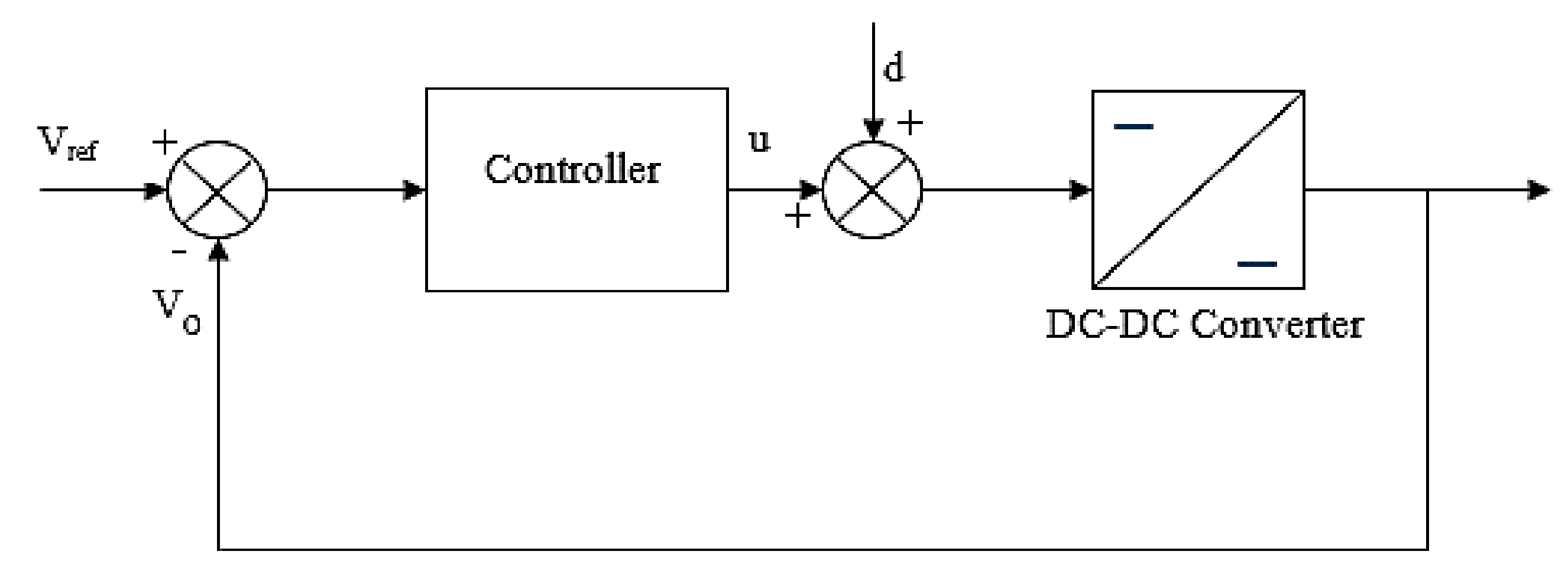
3. Controller Design
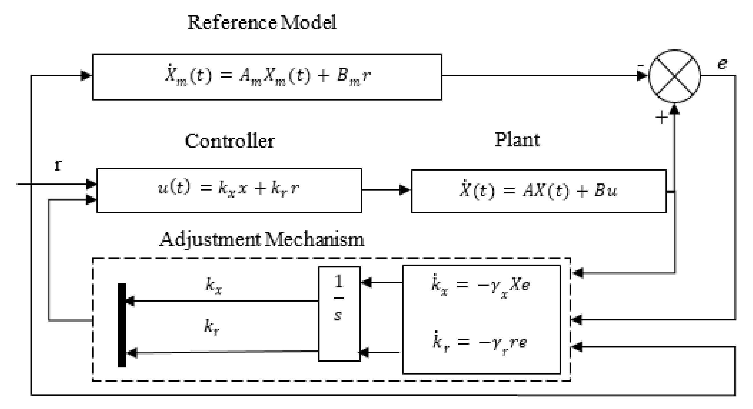
This section describes the designing of both the PI and the DMRAC controller. Therefore, this section is divided into two sub-sections: (1) DMRAC design and (2) PI design.

3.1. DMRAC Design

In order to design a DMRAC, a reference model was required to be designed primarily as follows:
X ˙ m t = A m X m t + B m r
where A m > 0 , and B m > 0 , are the parameters of the reference model and r is defined as the reference point.
Meanwhile, a control law was deduced for the state feedback control as:
u t = k x X + k r r
Here, k x and k r are considered as the adjustable gains.
The main objective was to ensure X t as X m t achieved the required performance. However, it was not exactly possible because A and B were considered as unknown system parameters. It was noted that the parameters of a DC–DC converter were considered as unknown, in order to tackle any unprecedented situation where the system could behave irregularly. Therefore, the error between the plant and reference model was required to be calculated as follows:
e t = X X m
Subsequently, error dynamics were addressed in the Equation as follows:
e ˙ t = A + B k x X A m X m + B k r r B m r
Hence, A m and B m were derived as follows to ensure e ˙ t 0
A + B k x = A m
B k r = B m
Since the system parameters were considered as unknown, another control law for estimation was addressed as follows:
u = k ^ x t X + k ^ r t r
where k ^ x t and k ^ r t are the estimated value of k x and k r , respectively, with respect to time.
A + B k ^ x t = A m
B k ^ r t = B m
As a result, the closed-loop error dynamics were demonstrated by replacing the values of A and B m as follows in Equation (11), and finally e ˙ t could be shown as follows:
u = k ^ x t X + k ^ r t r
where k ^ x k x = k ˜ x , k ^ r k r = k ˜ r .
In order to ensure system stability, a Lyapunov function candidate was considered. Here, γ is an adaptation gain rate that is responsible for converging the error [32].
Figure 2 demonstrates the complete process of the adaptive controller to make the process comprehensible, where plant X ˙ t is updated continuously according to the reference model X ˙ m t , based on error and error dynamics that make a significant contribution to control input, u t of the system, with the help of the adjustment mechanism and hence, the complete DMRAC works. Figure 3 shows how a DC-DC converter is integrated into a circuit and controlled by a controller.
Reference Model: Here, the reference model was designed, based on the output’s characteristics such as 0.2 s rise time, <0.5 s settling time and 0% overshoot. Therefore, the state-space model of the reference model could be developed by considering Equations (1)–(3) as follows:
A m = 720 8100 1 0 ,   B m = 1 0 ,   C m = 0 8100

3.2. PI Controller Design

The PI controller with a DC–DC converter is very well known, as it is simple to design and offers reasonably satisfactory performance. The conventional PI controller can be expressed as follows:
e t = X d X a
u t = K p + K i s
where, X d represents the desired states and X a defines the actual states. In addition, K p is known as proportional gain and K i is known as integral gain.
The gains drive the controllers to perform efficiently and therefore, choosing a suitable gain was very crucial for the controllers. Despite the fact that several methods were available to find a suitable gain, in this work, the gains for both PI and DMRAC were chosen based on a trial-and-error approach, as it is simple. Table 2 represents the parameters of both DMRAC and PI controller used in this simulation.

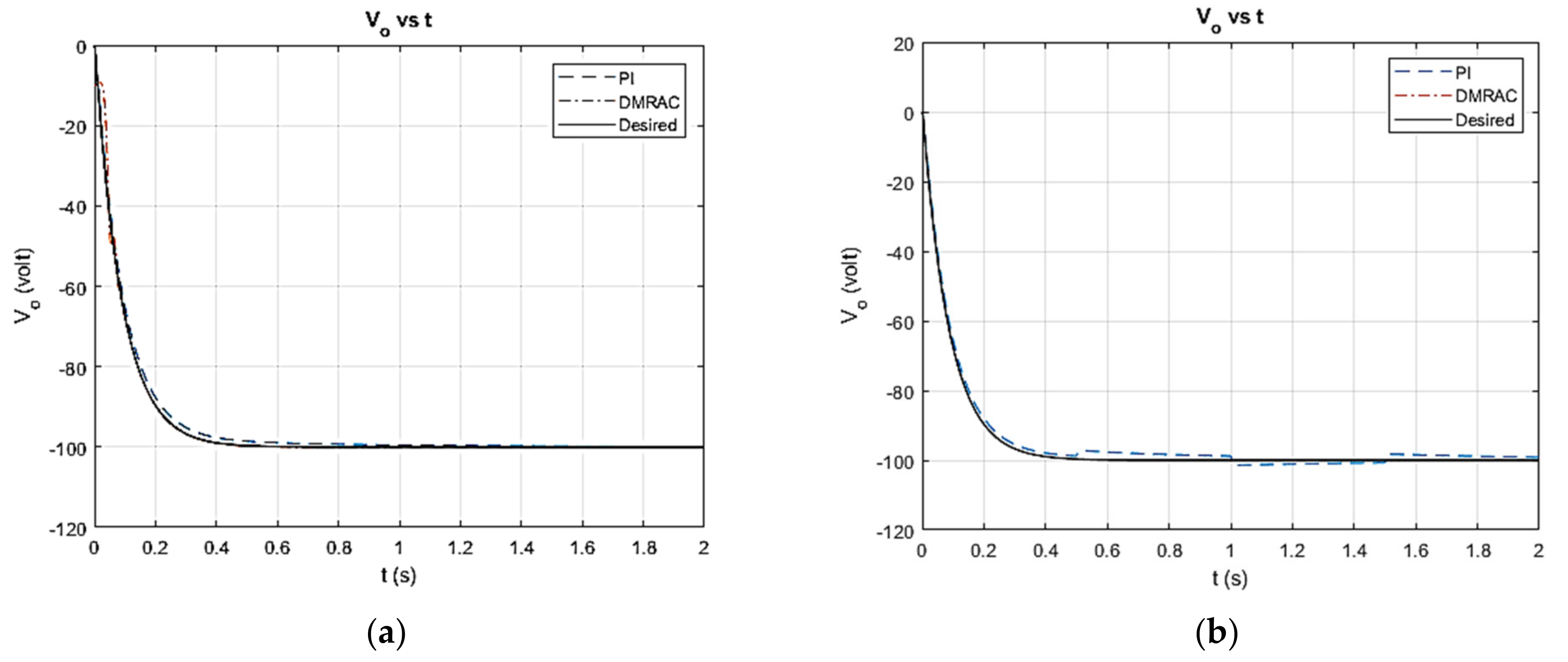
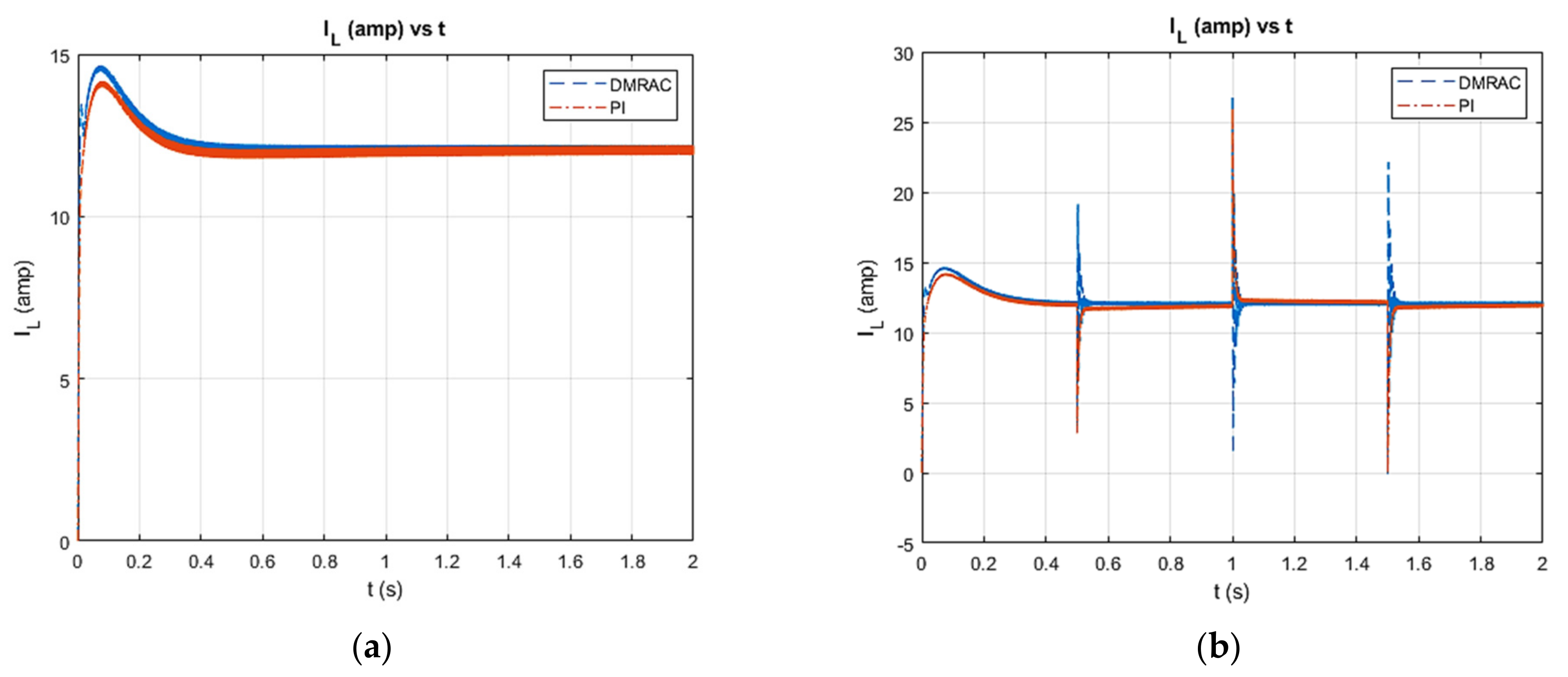
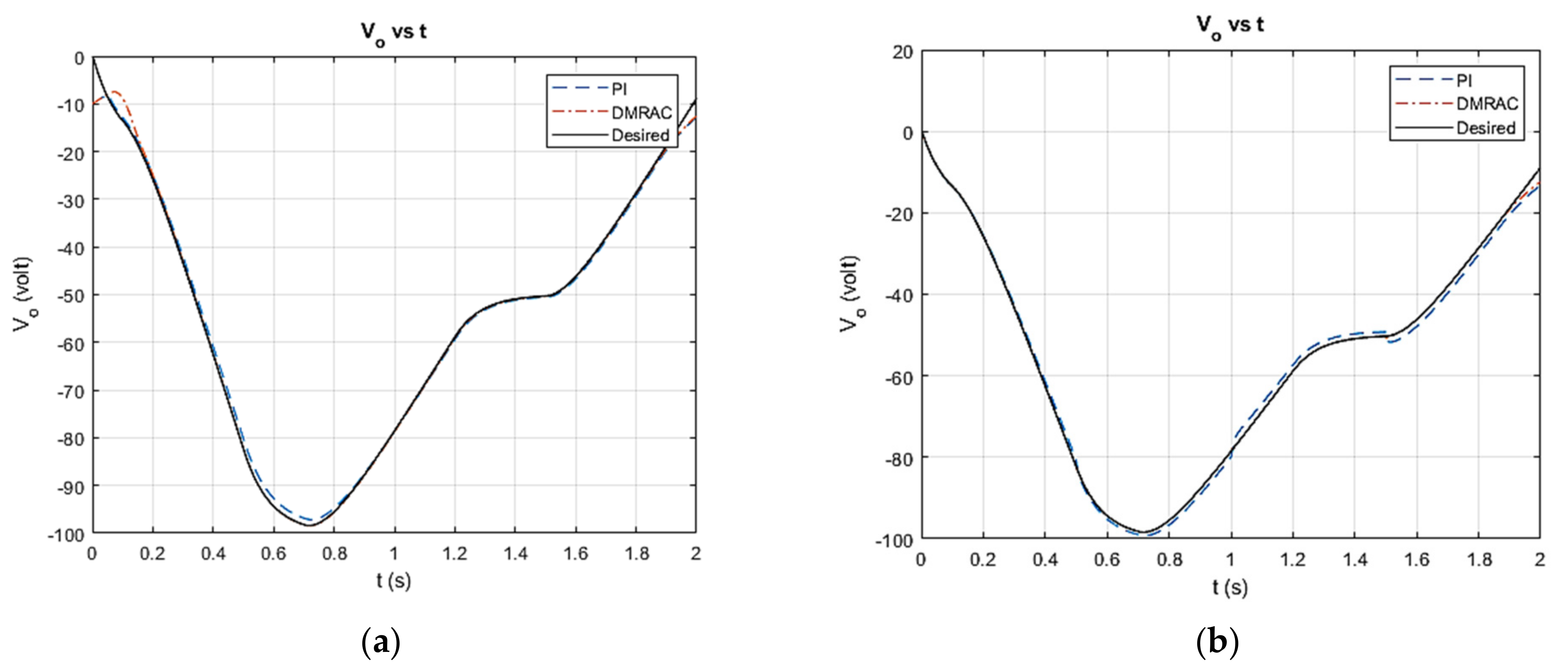
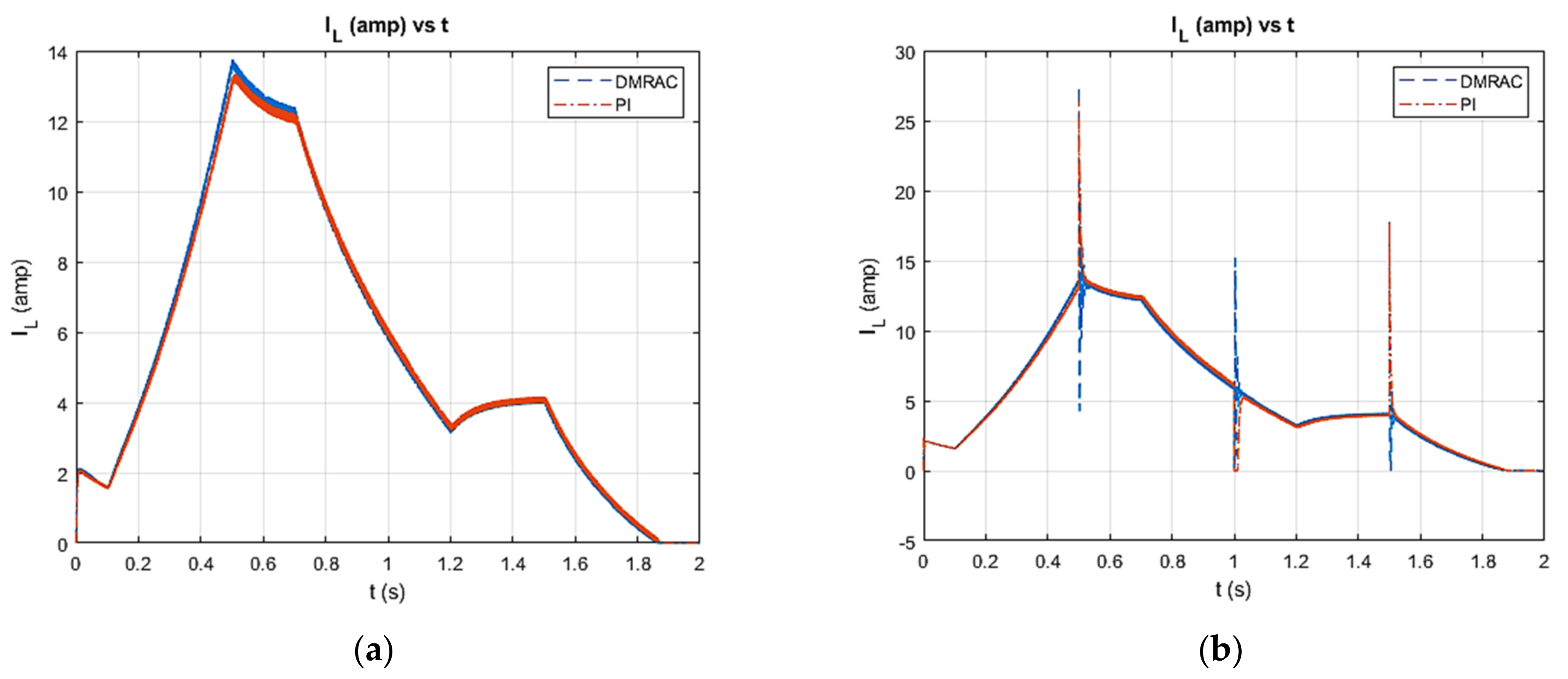
4. Simulated Results

This section provides a comparative discussion on the performance of the two controllers, PI and DMRAC. In this work, tracking performance was considered as the performance index. To analyze the tracking performance, two simulation cases were considered: (a) voltage tracking in the presence of disturbance; and (b) voltage tracking without the presence of disturbances. Here, Figure 3 portrays the block diagram of the system, specifically when the system is under disturbances, where u is the control input, and d is the disturbance to the system. In this block diagram, the controller block can be replaced by any of the controllers. Hence, it describes the primary functions of the controllers with the system in both cases, either with disturbance or without disturbance.
Figure 4a demonstrates the constant voltage tracking with the help of the PI and the DMRAC controllers. Here, it was noticed that both the PI and DMRAC were able to track the voltage, but DMRAC tracked more accurately than PI. As shown in Figure 4b, in the presence of disturbance to the system, PI showed some small fluctuations during tracking, while DMRAC maintained almost similar accuracy in the presence of disturbances. We noted that a Gaussian noise had been applied to the controller output, as a disturbance to the system.
Figure 5 describes the inductor’s current signal in the presence of the PI and the DMRAC controllers. In both cases, the DMRAC and PI offer an almost similar effort in inductor current in order to track the voltage. It was noticed from Figure 5b that in every 0.5 s, disturbances were added at the controller output and, as a result, the inductor current rose suddenly.
In addition, the performance of the controllers was measured, based on a simulation close to a real scenario of an EV driving mode, where the load demand varies with respect to time. In Figure 6a, the voltage demand increased from 0 V to 100 V within 0.6 s, as the electric vehicle was in an acceleration mode and immediately dropped to 55 V within 0.5 s when it was in a regenerative braking system mode. Then, for a 0.2 s period of time, the voltage demand remained constant, and then immediately dropped down again to make the car stop completely within a 0.5 s period of time. Therefore, this trajectory describes the three driving modes, such as acceleration mode, steady-state mode and regenerative breaking mode, and this simulation is suitable for the analysis of the controllers’ performance in voltage tracking.
Figure 6a describes the variable voltage tracking in ideal conditions, using both the PI and DMRAC control approach. It was prominently visible that a PI controller was able to track the trajectory with some deviations, while DMRAC tracked with higher accuracy. Similarly, in Figure 6b, the disturbance distracted the performance of both the controllers. It was noticed that the PI controller deviated more than DMRAC. Similar to Figure 5, both the controllers’ fluctuations were almost similar along inductor currents in both cases, as shown in Figure 7, and hence, both the controllers required almost the same control effort. Because of the disturbances in the system as shown in Figure 6b, they offered fluctuation every 0.5 s.
The performance of both the controllers can be better understood with the help of a Root Mean Square Error (RMSE) approach, as shown in Table 3. In this approach, the error between the desired trajectory and actual trajectory were compared with respect to the desired trajectory for every single time step. RMSE can be demonstrated as the following equation [33]:
R M S E = y a y d 2 l e n g t h   o f   y
where y a represents the actual values of y , and y d symbolizes the desired values of y .
In order to represent the tracking performance of the controllers in an efficient manner, Table 3 shows the tracking error of the controllers in all four different cases. Here, in every case, PI was found to be poor in overcoming a tracking error compared with DMRAC. Hence, it can be concluded that DMRAC is more efficient in tracking than a PI controller.
Table 4 provides the performance of the controllers in terms of the time response characteristics for the EV driving mode simulation. Here, DMRAC performed better than the PI controller in all four different cases, with its lesser errors. Apart from that, Table 4 also shows the dominance of DMRAC over PI in terms of performance, though it is minute. DMRAC offered the least settling time, rise time and peak time, except overshoot, albeit it was also near to zero.
Hence, a DMRAC can be considered as a suitable controller for a buck–boost converter, both in an ideal and disturbed situation, to track load demand accurately with a satisfactory outcome.

5. Discussion

A DMRAC is a nonlinear controller that is suitable when a system is generally affected by noise, disturbance and uncertain parameters. In this work, the disturbance was unknown to the controller and at the same time, it managed to track voltage very efficiently, with minimal RMSE errors of 0.0003% and 0.0321% when it tracked constant voltages and variable voltages in the presence of disturbances, respectively. In the meantime, a fixed gain controller, PI, also offered satisfactory behavior with some small fluctuations and RMSE errors of 0.8477% for constant voltage and 0.1661% variable voltage, when the system is affected by disturbances. Here, the DMRAC updated its adaptation gain continuously with respect to time, giving an advantage to this controller, while PI did not have the feature to adapt itself in the presence of uncertainty, causing it to show some unsmooth behavior. Apart from that, the DMRAC demonstrated a comparatively more satisfactory step response than the PI controller, which indicated that DMRAC was faster in response than the PI controller. A recent work can be cited to compare the performance of this controller [31]
In the simulation, the inductor current, which was considered as a control input, showed a spike in the presence of disturbances that happened because of the sudden rise in disturbance. As it is beyond the control of DMRAC, future works should consider adding a low pass filter to remove the spike of current from the system.
From the design perspective, the DMRAC was more complicated than the PI controller to implement, as it required a suitable reference model, and at the same time, Lyapunov stability had to be ensured, which is one of the most difficult parts for any system. As the control law was not changed in this work, the stability checking was avoided. In contrast, the PI controller was simpler than DMRAC, and choosing its gains was not tricky. However, choosing a suitable controller required a trade-off between the advantages and drawbacks of a controller, and its application as well. Since voltage demand needed to be met, even in a fraction of a second, in the presence of uncertainty to the system, DMRAC could be considered as a suitable controller for this application. Even though the simulation results demonstrate the potentiality of our proposed controller, tailoring the proposed method with an electric vehicle will be challenging, as there will be many factors that need to be considered. It is difficult to guarantee that factors such as overvoltage and internal resistance will not impair performance. We present the following elements as study limitations, which will be addressed in future works that take into account our tool and approach choices:
(i)
At the time of writing, the proposed method was not integrated with the electrical vehicle, representing a challenge to confidently assess the performance of our methods.
(ii)
The experimental results are presented in terms of Simulink simulations, which may produce different results, while considering various factors, such as voltage, resistance and so on.
(iii)
During this study, we did not compare our proposed model with the currently used DC–DC converters for electrical vehicles, as our proposed methods were in the development stage, while many of the existing algorithms are implemented in real-world scenarios. Thus, a reliable performance comparison would be expected once our proposed method is implemented with an electrical vehicle.
Our study did not explore the compatibility of our proposed method with a real- world scenario, and from a translational perspective, future works should explore the opportunity to bridge that gap with higher priority. Hence, in order to apply it in any hardware, dSPACE integrated with MATLAB will be initially considered to run the simulation. Note that dSPACE is an industrial software that is widely used in the automotive industry for any simulation work of electrical equipment, since it can directly deal with hardware through the MATLAB/Simulink environment. As a result, it offers researchers the opportunity to work directly with the hardware.

6. Conclusions

This work focuses on the boost mode of a buck–boost converter that incorporates battery discharge when an electric vehicle requires load to run the motor. The notability of this work was to introduce DMRAC with a buck–boost converter in order to maintain the load demand, according to the motor’s demand. Therefore, this study fills the gap in the literature on a controller with a buck–boost converter, through introducing a DMRAC algorithm. We noticed that the performance of DMRAC is significantly better in terms of voltage tracking and characteristics, i.e., smaller overshoot, faster settling time, smaller rise time and lower peak time than a PI controller. Hence, a DMRAC can be considered as a suitable controller for voltage tracking with a buck–boost converter in the presence of unknown parameters and uncertainty to the system. In the future, this work will be extended by considering a hybrid energy storage system of a lithium-ion battery and a supercapacitor with a buck–boost converter.

Author Contributions

Conceptualization, M.I. and A.F.A.G.; methodology, M.I. and A.F.A.G.; software, M.I.; validation, M.I. and A.F.A.G.; formal analysis, M.M.A., M.I., A.F.A.G., A.Z.K. and P.M; writing—original draft preparation, M.I.; writing—review and editing, A.F.A.G., E.S., M.M.A., A.Z.K. and M.A.P.M.; supervision, A.F.A.G.; project administration, A.F.A.G.; funding acquisition, A.F.A.G. All authors have read and agreed to the published version of the manuscript.

Funding

This research was funded by the International Islamic University Malaysia Research Acculturation Grant Scheme 2018, grant number IRAGS18-013-0014, and the Ministry of Higher Education Malaysia.

Data Availability Statement

The data presented in this study are available on request from the corresponding author.

Conflicts of Interest

The authors declare no conflict of interest.

Nomenclature

CCapacitor
D R Duty cycle
I L Inductor current
RResistance
VCCapacitor voltage
VbBattery voltage
γ Adaptation gain rate

References

  1. Emadi, A.; Lee, Y.J.; Rajashekara, K. Power electronics and motor drives in electric, hybrid electric, and plug-in hybrid electric vehicles. IEEE Trans. Ind. Electron. 2008, 55, 2237–2245. [Google Scholar] [CrossRef]
  2. Ghorbani, R.; Bibeau, E.; Filizadeh, S. On conversion of hybrid electric vehicles to plug-in. IEEE Trans. Veh. Technol. 2010, 59, 2016–2020. [Google Scholar] [CrossRef]
  3. Khan, F.; Tolbert, L. Bi-directional power management and fault tolerant feature in a 5-kW multilevel dc–dc converter with modular architecture. IET Power Electron. 2009, 2, 595–604. [Google Scholar] [CrossRef] [Green Version]
  4. Amjadi, Z.; Williamson, S.S. Power-electronics-based solutions for plug-in hybrid electric vehicle energy storage and management systems. IEEE Trans. Ind. Electron. 2009, 57, 608–616. [Google Scholar] [CrossRef]
  5. Wai, R.-J.; Shih, L.-C. Design of voltage tracking control for DC–DC boost converter via total sliding-mode technique. IEEE Trans. Ind. Electron. 2011, 58, 2502–2511. [Google Scholar] [CrossRef]
  6. Yazici, I.; Yaylaci, E.K. Fast and robust voltage control of DC–DC boost converter by using fast terminal sliding mode controller. IET Power Electron. 2016, 9, 120–125. [Google Scholar] [CrossRef]
  7. Nizami, T.K.; Mahanta, C. An intelligent adaptive control of DC–DC buck converters. J. Frankl. Inst. 2016, 353, 2588–2613. [Google Scholar] [CrossRef]
  8. Sahin, E.; Ayas, M.S.; Altas, I.H. A PSO optimized fractional-order PID controller for a PV system with DC-DC boost converter. In Proceedings of the 2014 16th International Power Electronics and Motion Control Conference and Exposition, Antalya, Turkey, 21–24 September 2014; pp. 477–481. [Google Scholar]
  9. Adnan, M.F.; Oninda, M.A.M.; Nishat, M.M.; Islam, N. Design and Simulation of a DC-DC Boost Converter with PID Controller for enhanced Performance. Int. J. Eng. Res. Technol. 2017, 6, 27–32. [Google Scholar]
  10. Po, L.; Ruiyu, L.; Tianying, S.; Jingrui, Z.; Zheng, F. Composite adaptive model predictive control for DC–DC boost converters. IET Power Electron. 2018, 11, 1706–1717. [Google Scholar] [CrossRef]
  11. David, B.M.; Sreeja, K. A Review of sliding mode control of DC-DC converters. Int. Res. J. Eng. Technol. 2015, 2, 1382–1386. [Google Scholar]
  12. Utkin, V. Sliding mode control of DC/DC converters. J. Frankl. Inst. 2013, 350, 2146–2165. [Google Scholar] [CrossRef] [Green Version]
  13. Ciccarelli, F.; Lauria, D. Sliding-mode control of bidirectional dc-dc converter for supercapacitor energy storage applications. In Proceedings of the SPEEDAM 2010, Pisa, Italy, 14–16 June 2010; pp. 1119–1122. [Google Scholar]
  14. Agarwal, A.; Deekshitha, K.; Singh, S.; Fulwani, D. Sliding mode control of a bidirectional DC/DC converter with constant power load. In Proceedings of the 2015 IEEE First International Conference on DC Microgrids (ICDCM), Atlanta, Georgia, 7–10 June 2015; pp. 287–292. [Google Scholar]
  15. Albiol-Tendillo, L.; Vidal-Idiarte, E.; Maixé-Altés, J.; Bosque-Moncusí, J.; Valderrama-Blavi, H. Design and control of a bidirectional DC/DC converter for an Electric Vehicle. In Proceedings of the 2012 15th International Power Electronics and Motion Control Conference (EPE/PEMC), Novi Sad, Serbia, 4–6 September 2012; pp. LS4d. 2-1–LS4d. 2-5. [Google Scholar]
  16. Massaoudi, Y.; Elleuch, D.; Gaubert, J.P.; Mehdi, D.; Damak, T. A new backstepping sliding mode controller applied to a dc-dc boost converter. Int. J. Power Electron. Drive Syst. 2016, 7, 759. [Google Scholar] [CrossRef]
  17. Benbaha, N.; Zidani, F.; Nait-Said, M.-S.; Zouzou, S.E.; Boukebbous, S.; Ammar, H. dSPACE Validation of Improved Backstepping Optimal Energy Control for Photovoltaic Systems. In Proceedings of the 2018 6th International Renewable and Sustainable Energy Conference (IRSEC), Rabat, Morocco, 5–8 December 2018; pp. 1–6. [Google Scholar]
  18. Saadatmand, S.; Shamsi, P.; Ferdowsi, M. The Heuristic Dynamic Programming Approach in Boost Converters. In Proceedings of the 2020 IEEE Texas Power and Energy Conference (TPEC), College Station, TX, USA, 6–7 February 2020; pp. 1–6. [Google Scholar]
  19. Abjadi, N.; Goudarzian, A.; Markadeh, G.R.A.; Valipour, Z. Reduced-Order Backstepping Controller for POESLL DC–DC Converter Based on Pulse Width Modulation. Iran. J. Sci. Technol. Trans. Electr. Eng. 2019, 43, 219–228. [Google Scholar] [CrossRef]
  20. Yi, L.-K.; Zhao, J.; Ma, D. Adaptive backstepping sliding mode nonlinear control for buck DC/DC switched power converter. In Proceedings of the 2007 IEEE International Conference on Control and Automation, Roma, Italy, 17–20 October 2007; pp. 1198–1201. [Google Scholar]
  21. Sureshkumar, R.; Ganeshkumar, S. Comparative study of Proportional Integral and Backstepping Controller for Buck Converter. In Proceedings of the International Conference on Emerging Trends in Electrical and Computer Technology, Nagercoil, India, 23–24 March 2011; pp. 375–379. [Google Scholar]
  22. Chakravarty, A.; Mahanta, C. Backstepping Enhanced Adaptive Second Order Sliding Mode Controller to compensate Actuator. In Proceedings of the India Conference (INDICON), Pune, India, 11–13 December 2014; pp. 1–6. [Google Scholar]
  23. Åström, K.J.; Wittenmark, B. Adaptive Control; Dover Publications: New York, NY, USA, 2013. [Google Scholar]
  24. Ardhenta, L.; Subroto, R.K. Application of direct MRAC in PI controller for DC-DC boost converter. Int. J. Power Electron. Drive Syst. 2020, 11, 851. [Google Scholar] [CrossRef]
  25. Shyu, K.-K.; Yang, M.-J.; Chen, Y.-M.; Lin, Y.-F. Model reference adaptive control design for a shunt active-power-filter system. IEEE Trans. Ind. Electron. 2008, 55, 97–106. [Google Scholar] [CrossRef]
  26. Djebbri, S.; Ladaci, S.; Metatla, A.; Balaska, H. Robust MRAC Supervision of a Multi-source Renewable Energy System Using Fractional-Order Integrals. In Proceedings of the 2018 International Conference on Electrical Sciences and Technologies in Maghreb (CISTEM), Algiers, Algeria, 29–31 October 2018; pp. 1–6. [Google Scholar]
  27. Pires, V.F.; Monteiro, J.; Silva, J.F. Dual 3-Phase Bridge Multilevel Inverters for AC Drives with Voltage Sag Ride-through Capability. Energies 2019, 12, 2324. [Google Scholar] [CrossRef] [Green Version]
  28. Vijayalakshmi, S.; T Raja, S.R. Time domain based digital controller for buck-boost converter. J. Electr. Eng. Technol. 2014, 9, 1551–1561. [Google Scholar] [CrossRef] [Green Version]
  29. Lai, C.-M.; Cheng, Y.-H.; Hsieh, M.-H.; Lin, Y.-C. Development of a bidirectional DC/DC converter with dual-battery energy storage for hybrid electric vehicle system. IEEE Trans. Veh. Technol. 2017, 67, 1036–1052. [Google Scholar] [CrossRef]
  30. Bellur, D.M.; Kazimierczuk, M.K. DC-DC converters for electric vehicle applications. In Proceedings of the 2007 Electrical Insulation Conference and Electrical Manufacturing Expo, Nashville, TN, USA, 22–24 October 2007; pp. 286–293. [Google Scholar]
  31. Devi Vidhya, S.; Balaji, M. Hybrid fuzzy PI controlled multi-input DC/DC converter for electric vehicle application. Automatika 2020, 61, 79–91. [Google Scholar] [CrossRef]
  32. Frank, S.A. Adaptive control. In Control Theory Tutorial; Springer: Berlin/Heidelberg, Germany, 2018; pp. 85–89. [Google Scholar]
  33. Islam, M.; Okasha, M.; Sulaeman, E. A model predictive control (MPC) approach on unit quaternion orientation based quadrotor for trajectory tracking. Int. J. Control Autom. Syst. 2019, 17, 2819–2832. [Google Scholar] [CrossRef]
Figure 1. A diagram of buck–boost converter.
Electronics 10 02516 g001
Figure 2. A block diagram of DMRAC (Direct Model Reference Adaptive Control) algorithm.
Electronics 10 02516 g002
Figure 3. A block diagram of a DC–DC converter (i.e., buck–boost converter) with a controller.
Electronics 10 02516 g003
Figure 4. Constant voltage tracking (a) without the presence of disturbance and (b) in presence of disturbance.
Electronics 10 02516 g004
Figure 5. Inductor current (a) without the disturbance in the system, and (b) in presence of the disturbance in constant voltage tracking.
Electronics 10 02516 g005
Figure 6. Variable voltage tracking (a) without the presence of disturbance in the system and (b) in presence of disturbance in the system.
Electronics 10 02516 g006
Figure 7. Inductor current (a) without the disturbance in the system and (b) in presence of the disturbance in variable voltage tracking.
Electronics 10 02516 g007
Table 1. Properties of the buck–boost converter and lithium-ion battery.
PropertiesValues
Inductance, L5 × 10−4 H
Capacitance, C9200 × 10−6 F
Capacitor initial voltage, VC10 V
Resistance, R25 Ω
Switching frequency50 kHz
Battery nominal voltage48 V
Battery rated capacity14 Ah
Battery initial SOC95%
Battery response time0.3 s
Table 2. Parameters of DMRAC and PI controller.
PropertiesValues
Rate of adaptation
γ x = 2
γ r = 2
Proportional gain, k p = 5
Initial gain
k x 0 = 11
k r 0 = 11
Integral gain, k i = 8
Table 3. RMSE for both DMRAC and PI controllers.
PropertiesRMSE Along Controllers
DMRAC (%)PI (%)
Constant voltage0.00050.6723
Constant voltage with disturbance0.00030.8477
Variable voltage0.03100.5149
Variable voltage with disturbance0.03210.1661
Table 4. Controllers’ characteristics for both DMRAC and PI controllers.
CharacteristicsControllers
DMRACPI
Settling time (s)0.34360.4122
Overshoot (%)0.00070.0003
Rise time (s)0.19210.2060
Peak time (s)1.98402.0000
Publisher’s Note: MDPI stays neutral with regard to jurisdictional claims in published maps and institutional affiliations.

