
Analysis and Verification of a Cogging Torque Reduction Method for Variable Flux Memory Permanent Magnet Machine


1
School of Intelligence Manufacturing, Huanghuai University, Zhumadian 463000, China
2
Department of Computer Science, University of Mysore, Manasagangotri, Mysore 570006, India
3
School of Electrical Engineering, Southeast University, Nanjing 210096, China
*
Author to whom correspondence should be addressed.
Electronics 2021, 10(16), 1913; https://doi.org/10.3390/electronics10161913
Submission received: 20 July 2021
/
Revised: 4 August 2021
/
Accepted: 6 August 2021
/
Published: 9 August 2021
(This article belongs to the Special Issue Recent Issues on Motors and Motor Drives)
Abstract
:In this paper, an analytical method based on the series transform and skewed slot structure of rotor is adopted to reduce the cogging torque of the variable flux memory permanent magnet (VFMPM) machine. Firstly, the theory analysis of the cogging torque of the VFMPM machine was completed. Secondly, a simulation model of the VFMPM machine was established, aiming at calculating the cogging torque of the VFMPM machine and verifying the correctness of the above analytical method. Thirdly, a prototype of 14 rotor slots and 12 stator slots of the VFMPM machine was manufactured, and the experimental results of the cogging torque of the VFMPM machine further verified the effectiveness of the above mentioned theory analysis. Besides, the load force of the VFMPM machine including the cogging torque was also tested and analyzed in this paper.
1. Introduction
Since the structure of rotor and stator of the flux switching machine is the salient pole type, the air-gap flux density of the flux switching machine is higher than some other kinds of machines [1,2,3]. In this condition, the magnetic saturation occurs in the teeth end of flux switching machine’s rotor and stator, which produces the cogging torque fluctuation when the flux switching machine is working [4,5]. The cogging torque fluctuation will lead to mechanical vibration and noise, which is disadvantageous for the constant-speed and constant-torque operation of the flux switching machine, especially in the low-speed condition [6]. As a kind of flux switching machine, the VFMPM machine also suffers from the effect of cogging torque fluctuation.
In order to reduce the amplitude of the cogging torque of machines, experts have proposed two kinds of methods, which are the operation control method and structure design method. References [7,8] proposed a method of harmonic current injection to compensate the cogging force of the linear synchronous motor. Reference [9] compared the cogging torque compensation of a motor by harmonic current injection and model predictive current control, which proved that the harmonic current injection method was ordinary and the model predictive current control was slightly superior. Reference [10] adopted a control method of field circuit coupling double closed-loop to improve the operational performance of the brushless machine, and the experimental results indicated that the torque ripple of brushless machine was small.
Besides, the main method of cogging torque reduction of the machine is structure design, such as extending the stator magnetic circuit [11], yokeless secondary [12], hybrid cores [13], asymmetric magnetomotive force and asymmetric permeance [14], angle of stator tooth and rotor pole [2], and so on. Comparatively, the structure design method is simpler and more economical than the operation control method, because the operation control method will involve control algorithm, current data collection, and hardware circuit, and will even conflict with the speed and torque control of the flux switching machine.
For the VFMPM machine, it has the characteristics of enhanced flux and weakened flux [15,16], which will improve the complexity of the operation control method. Therefore, professor Yang Hui, etc. has proposed the stepwise magnetization control method to investigate the operational performance of the VFMPM machine [17]. Although the structure of the VFMPM machine is similar to the classic structure of the flux switching permanent magnet (FSPM) machine [18,19], the cogging torque of the VFMPM machine has not been researched thoroughly, because the VFMPM machine requires the special working condition of enhanced flux and weakened flux. Therefore, the main work of this paper is to investigate the cogging torque reduction of the VFMPM machine, including the working condition of enhanced flux and weakened flux.
This paper is organized as follows. Firstly, an analytical expression based on the series transform and skewed slot structure of the rotor was adopted to investigate the principle of cogging torque of the VFMPM machine. With the analytical expression, the cogging torque reduction method of the VFMPM machine was achieved. Secondly, a simulation model was established to calculate the cogging torque of the VFMPM machine in different flux regulation conditions (enhanced flux and weakened flux), and verify the validation of the above analytical method preliminarily. Thirdly, a prototype of the VFMPM machine and test rig was constructed, and the experimental results were identical with those of the simulation model. Besides, the load force of the VFMPM machine, including the cogging torque, were also tested and analyzed in this paper.
2. Theory Analysis of Cogging Torque
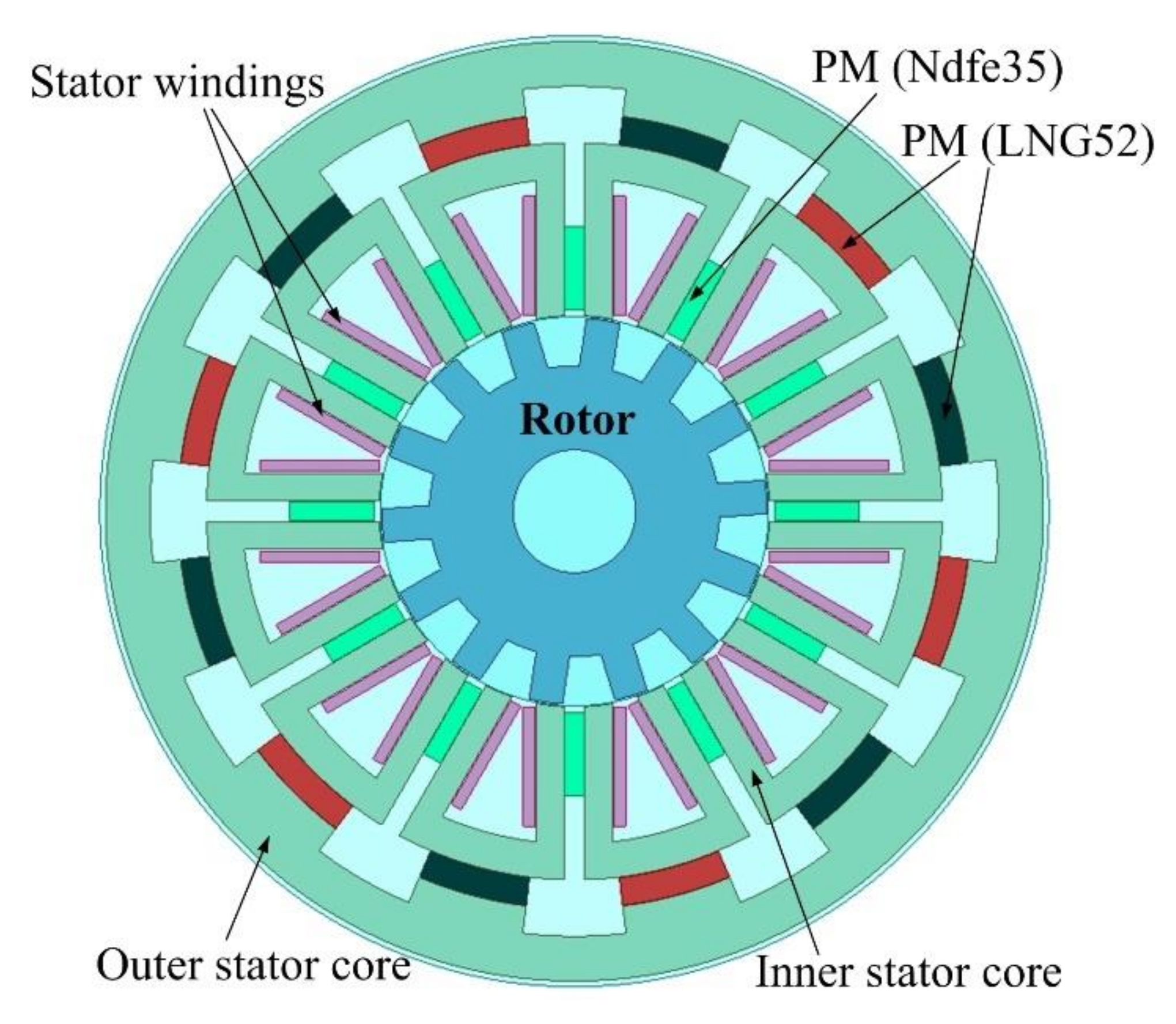
The VFMPM machine involved in this paper is shown in Figure 1. In Figure 1, the structure of rotor and inner stator core is the salient pole type. The operation principle of the VFMPM machine can be seen in [16]. When the relative motion between rotor and stator occurs, the cogging torque will be produced by the theory of magnetic energy variation [20]. For the cogging torque, the amplitude of magnetic energy variation is only decided by the permanent magnet (Ndfe35 and LNG52 in the VFMPM machine). Reference [21] had proposed the theory analysis of cogging torque based on the rotor tooth of the flux switching machine. This paper adopted the analytical method on the basis of the stator tooth of the VFMPM machine, and made a further simple derivation.
2.1. Analysis of Cogging Torque with Stator Straight Slot
It is assumed that only one tooth (straight slot) exists in the inner stator core of the VFMPM machine, which is named as the stator tooth; then the corresponding cogging torque of the VFMPM machine can be expressed as
where is the amplitude of the cogging torque with harmonics component, is the number of rotor tooth, and is the relative position angle between rotor tooth and stator tooth (mechanical angle). Based on the Equation (1), the cogging torque of stator tooth can be described as
where is the number of stator teeth. Make a comparison between Equation (2) and Equation (1); it can be found that there is only the phase difference occurring among the cogging torque of a different stator tooth.
Thus, the total cogging torque of the VFMPM machine can be described as
In Equation (3), if and , then Equation (3) can be rewritten as
by the analytical expression of Fourier series of trigonometric function, Equation (4) can be transformed into
In Equation (5), the analytical expression ( and are integral numbers). Therefore, only the analytical expression , then Equation (5) can exist.
For the actual structure of the VFMPM machine, should be as small as possible to prevent the high harmonic proportion of cogging torque.
2.2. Analysis of Cogging Torque with Stator Skewed Slot
Equation (3) shows the cogging torque expression of the VFMPM machine with a stator straight slot. Now we analyze the cogging torque expression of the VFMPM machine with a stator skewed slot.
If the stator core is divided into segments (in the radial direction), and the adjacent parts of the stator core are rotated by mechanical angle, Equation (3) can be rewritten as
It is assumed and , then Equation (7) can be transformed into
In Equation (8), only when the expression of numerator , then the cogging torque is reduced. For an example of a VFMPM machine with 12 stator slots and 14 rotor slots, the adjacent mechanical angle of the stator core with 2 segments is
where (see Equation (6)), and the total shifted mechanical angle is . Besides, when the adjacent mechanical angle is , the expression of denominator , which indicates Equation (9) is reasonable.
2.3. The Influence of Pole-Arc Coefficient on the Cogging Torque
Actually, before reducing the cogging torque of the VFMPM machine by the suitable skewed slot degree of rotor, the pole-arc coefficient (tooth width and slot width of rotor and stator) should be optimized first. If the pole-arc coefficient is larger, then the magnetic saturation will occur in the teeth of the rotor and stator of the VFMPM machine, which is not a benefit for the operational performance of the VFMPM machine.
Therefore, we have investigated and optimized the pole-arc coefficient of the VFMPM machine in Reference [16] comprehensively, and the pole-arc coefficient is determined as 1.2.
3. Simulation and Calculation
Because of the complex structure, it is impossible to achieve the skewed slot in the stator core of the VFMPM machine. However, we can achieve a skewed slot in the rotor core of the VFMPM machine, because the cogging torque is produced by the interaction of rotor core and stator core. In this section, the software ANSYS is used to build a simulation model and calculate the cogging torque of the VFMPM machine, aiming at verifying the correctness of the theory analysis above. The ANSYS is a finite element simulation and calculation software, which can be used in structural mechanics, hydrodynamics, circuit science, electromagnetism, thermodynamics, acoustics, etc.
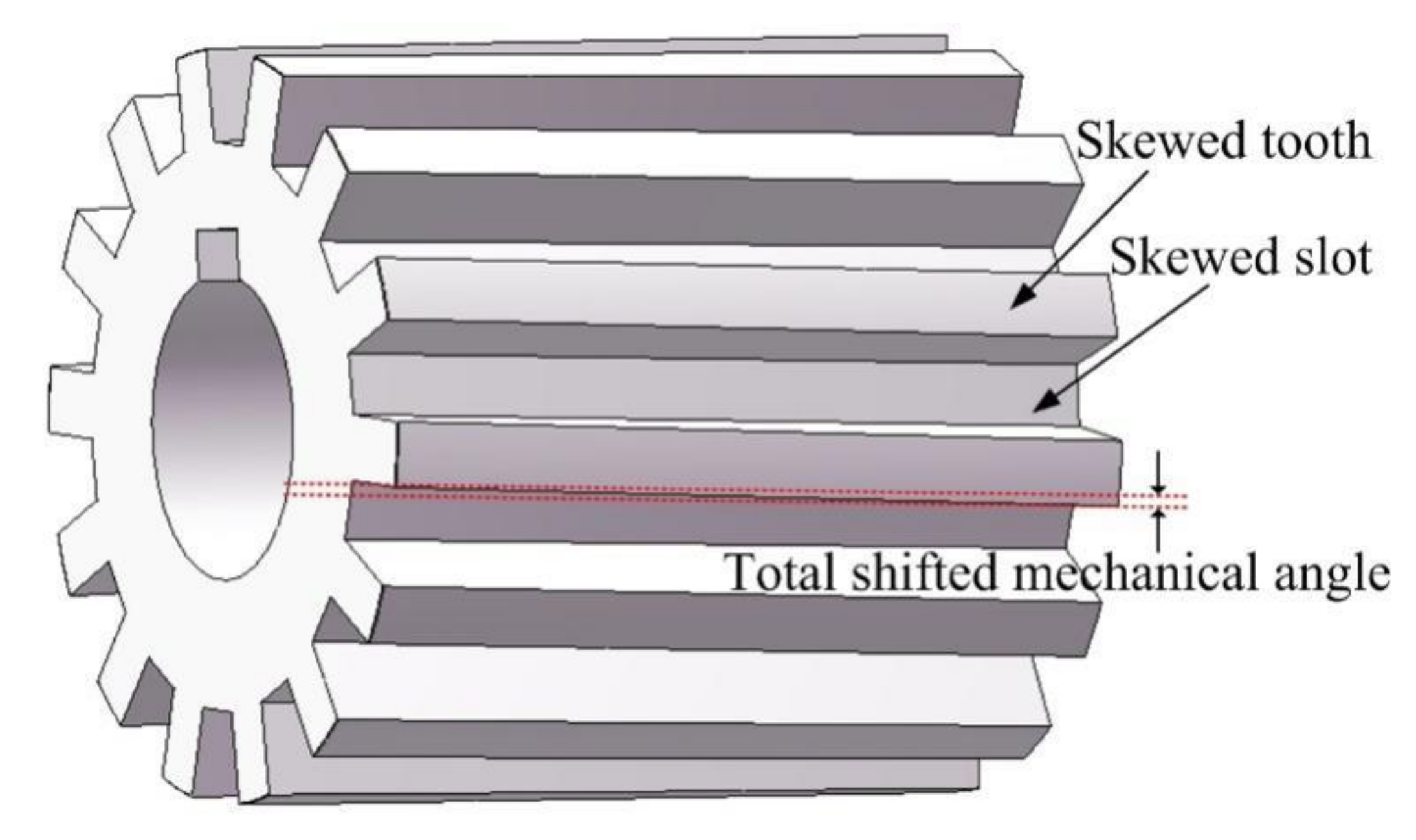
For example, if the 12 stator slots and 14 rotor slots of the VFMPM machine are divided into 10 segments, the adjacent mechanical angle is , and the total shifted mechanical angle is . For another example, if the VFMPM machine is divided into 100 segments, then the adjacent mechanical angle is , and the total shifted mechanical angle is also . This means that no matter how many segments are divided, the total shifted mechanical angle of the VFMPM machine remains . Therefore, if the rotor core is divided into many segments, then the rotor core slot of the VFMPM machine can be considered as a continuous skewed slot, as shown in Figure 2.
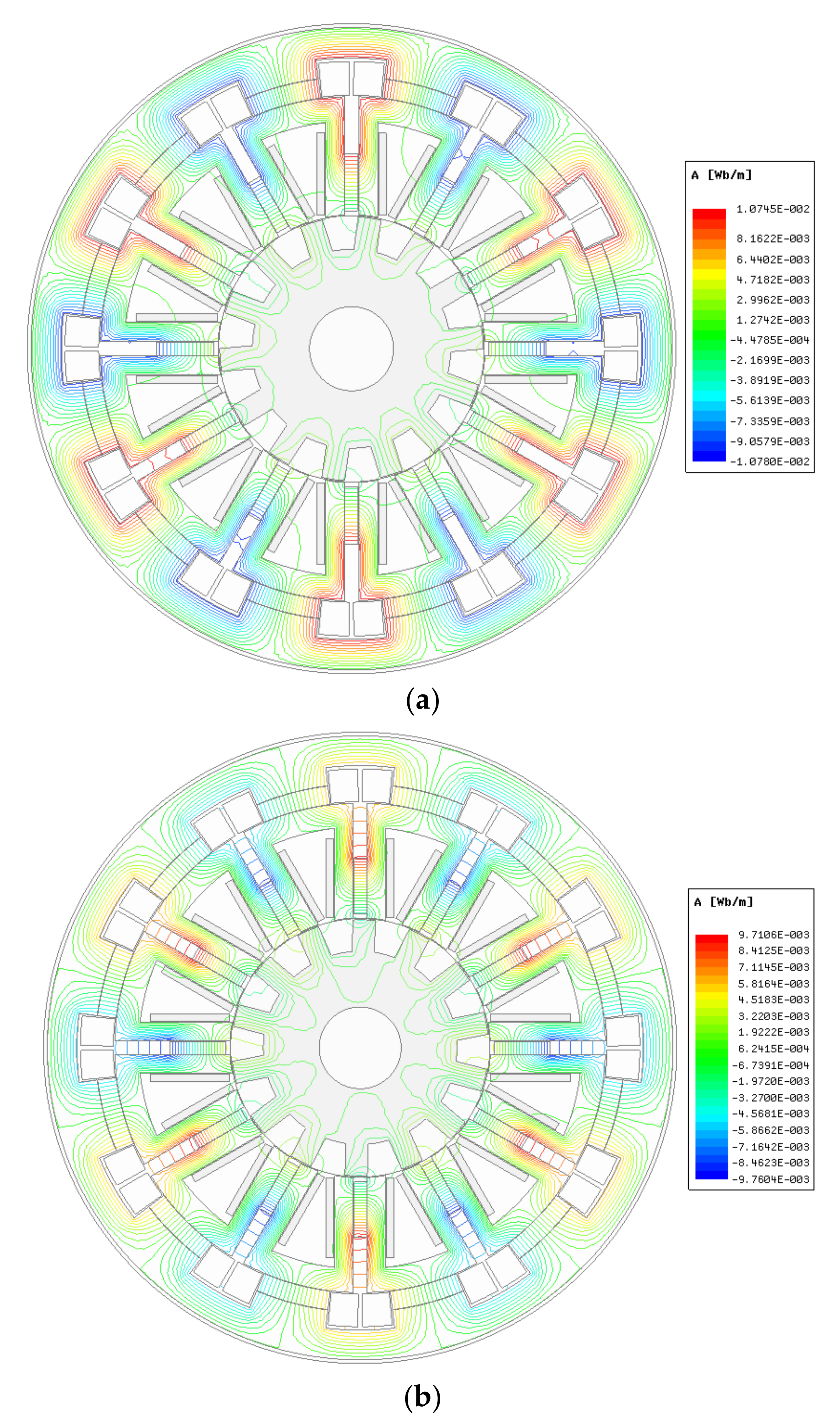
In order to calculate the cogging torque of the VFMPM machine accurately, a two-dimensional model of the VFMPM machine is achieved by the finite element analysis software, as illustrated in Figure 3. In order to calculate conveniently by the simulation software, the total skewed slot degree (total shifted mechanical angle) of the rotor of the VFMPM machine is 5° (divided into 5 segments, and the adjacent mechanical angle is ). Figure 3a shows the vector magnetic potential distribution of the VFMPM machine in the weakened flux condition, and Figure 3b describes its enhanced flux condition. The dimension parameters of the VFMPM machine are shown in Table 1. The principle of weakened flux and enhanced flux of the VFMPM machine can be seen in Reference [16]. By comparison, the air-gap magnetic potential distribution of weakened flux condition is lower than the enhanced flux condition’s, which means that the amplitude of back EMF of weakened flux condition is lower than the enhanced flux condition’s amplitude (at the same speed), and the same is the cogging torque amplitude.
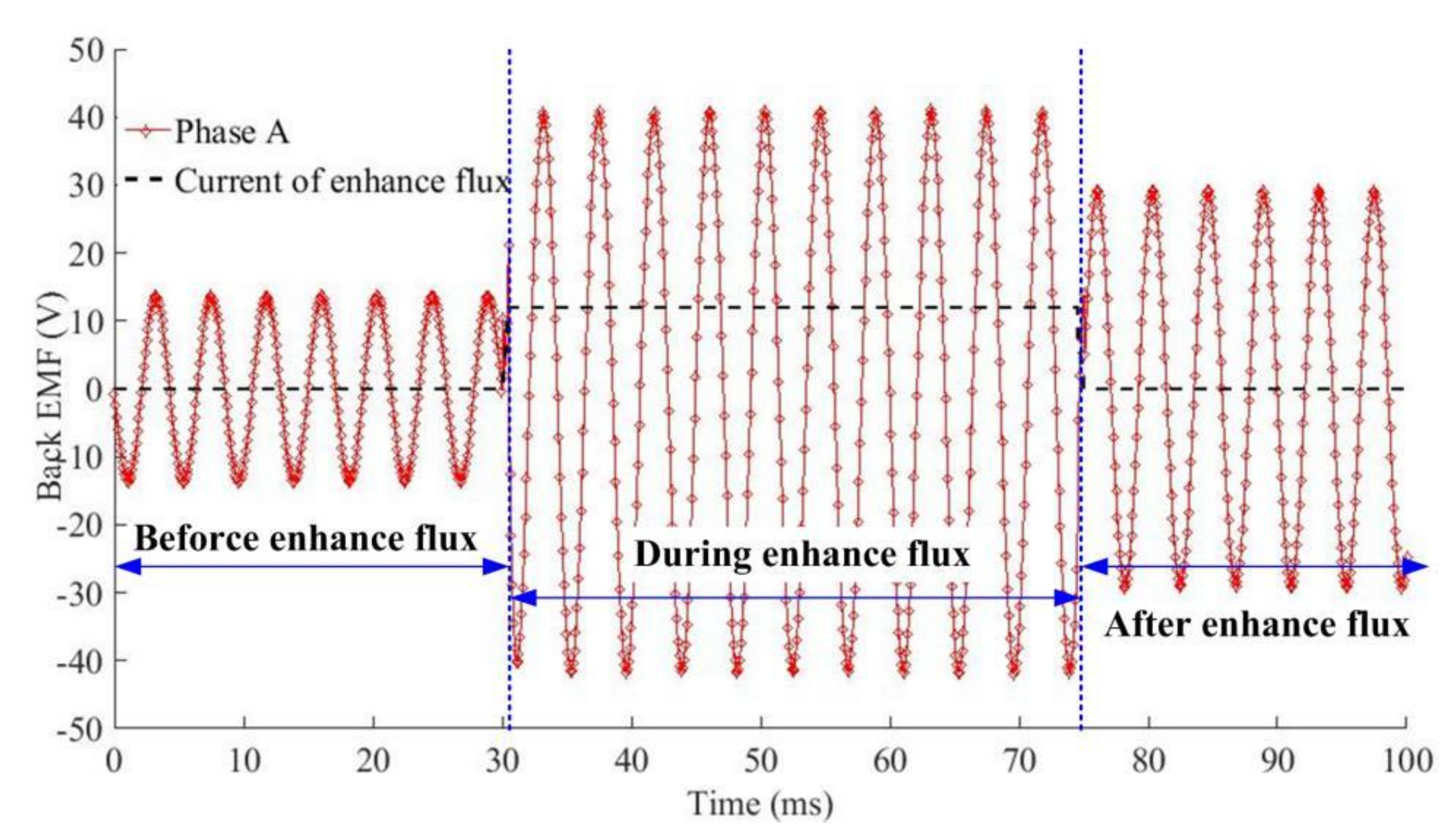
By the simulation model, Figure 4 shows the back EMF variation of the VFMPM machine in the enhanced flux process, and the enhanced flux current is 12 A. After the enhanced flux, the amplitude of back EMF of the VFMPM machine can be increased from 13.5 V to 29.2 V. When the enhanced flux current is larger than 15 A, the amplitude of back EMF of the VFMPM machine will no longer increase (about 32.5 V), which indicates that the maximum work point of permanent magnet LNG52 can be achieved by the 15 A of enhanced flux current.
Besides, before or after enhanced flux, the total harmonic distortion (THD) of back EMF is nearly constant, which is 1.91% and 1.84%, respectively [16]. This phenomenon will benefit the optimization control of the VFMPM machine.
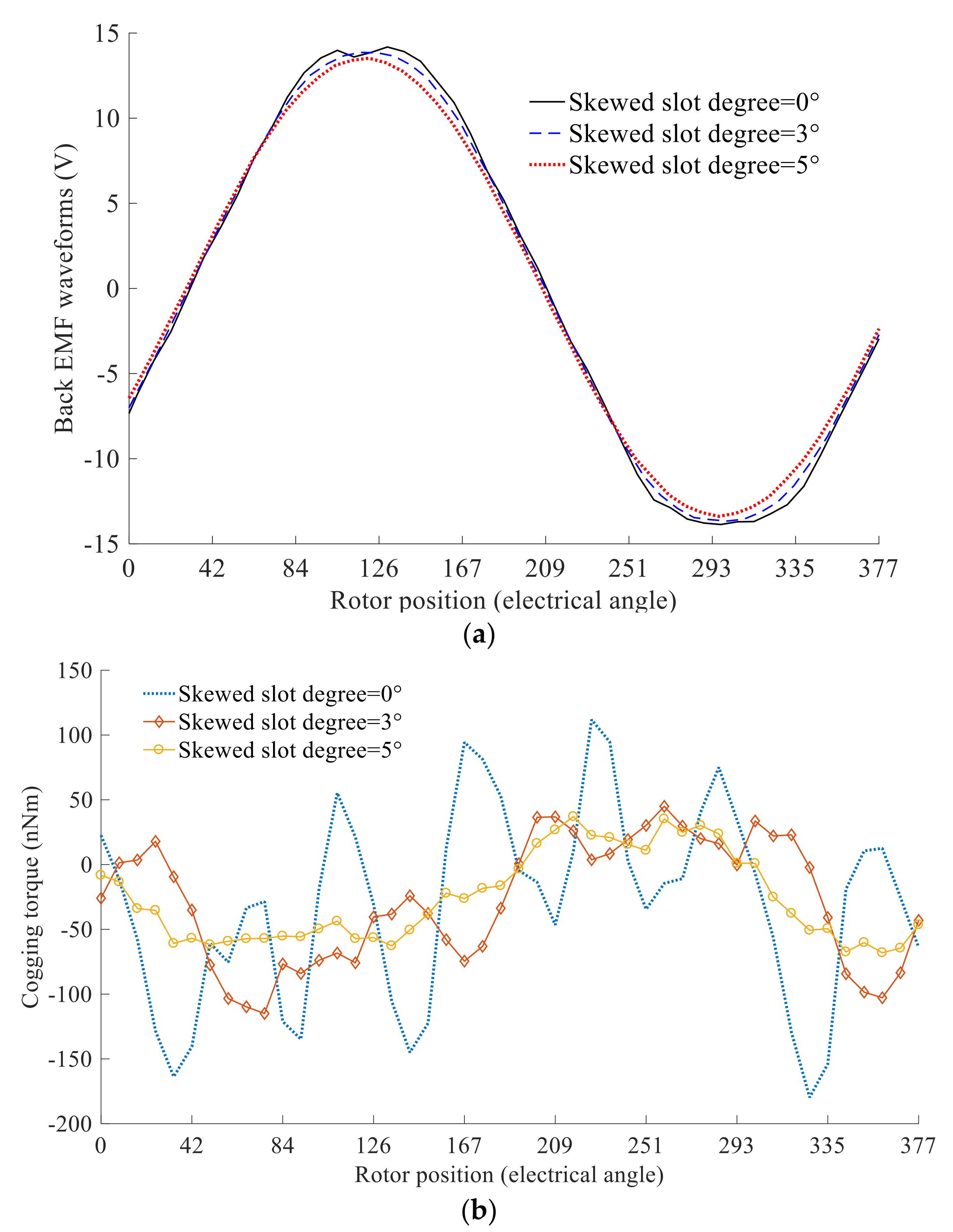
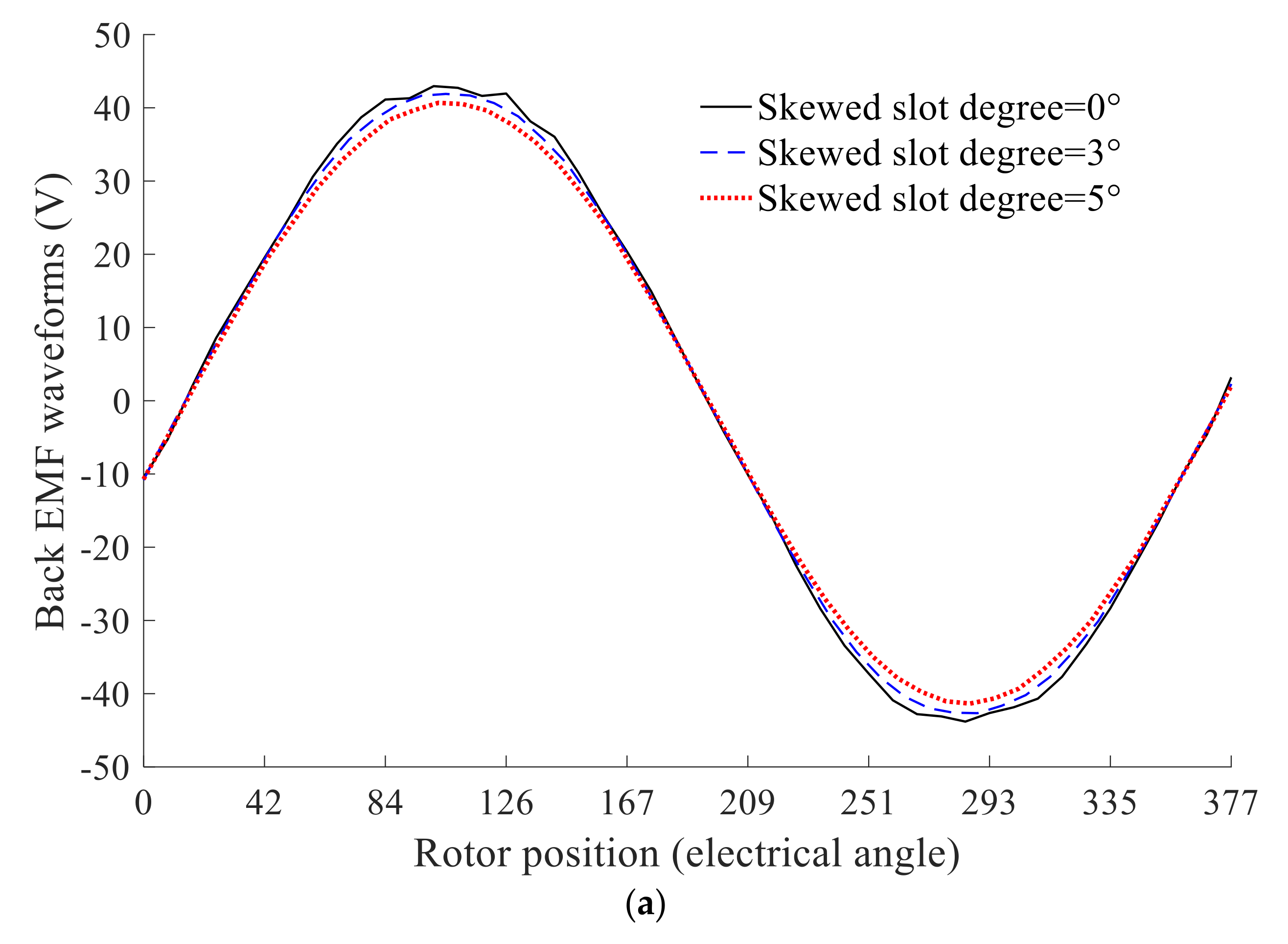
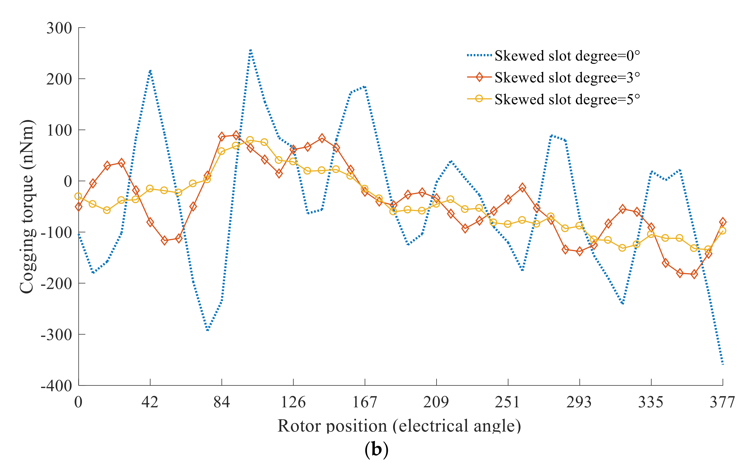
Figure 5 shows the simulation results of the VFMPM machine in weakened flux condition. The comparison results of Figure 5a indicate that the back EMF waveform of rotor skewed slot type (skewed slot degree = 5°) is more sinusoidal than the rotor straight slot type (skewed slot degree = 0°), and Figure 5b reveals that the cogging torque amplitude can be decreased dramatically by the rotor skewed slot type (5°). Figure 6 shows the simulation results of the VFMPM machine in enhanced flux condition. After the enhanced flux, the amplitudes of back EMF waveforms are increased (compared with the weakened flux condition), and the sinusoidal degree of back EMF waveform of rotor skewed slot type (5°) is still higher than the rotor straight slot type (0°), as shown in Figure 6a. Figure 6b also shows that the cogging torque can be decreased in the enhanced flux condition of rotor skewed type (5°).
Actually, the back EMF waveform of rotor skewed slot degree = 5° is equal to the average value of rotor straight slot, which is located at the 0°, 1°, 2°, 3°, 4°, 5° degree of rotor, respectively. Due to the existence of phase difference, the amplitude of back EMF waveform of rotor skewed slot type is lower than the rotor straight slot type’s. The detailed explanation is shown in Appendix A.
Consequently, the simulation and comparison results indicate that the above theory analysis for cogging torque reduction is reasonable.
4. Experiment and Comparison
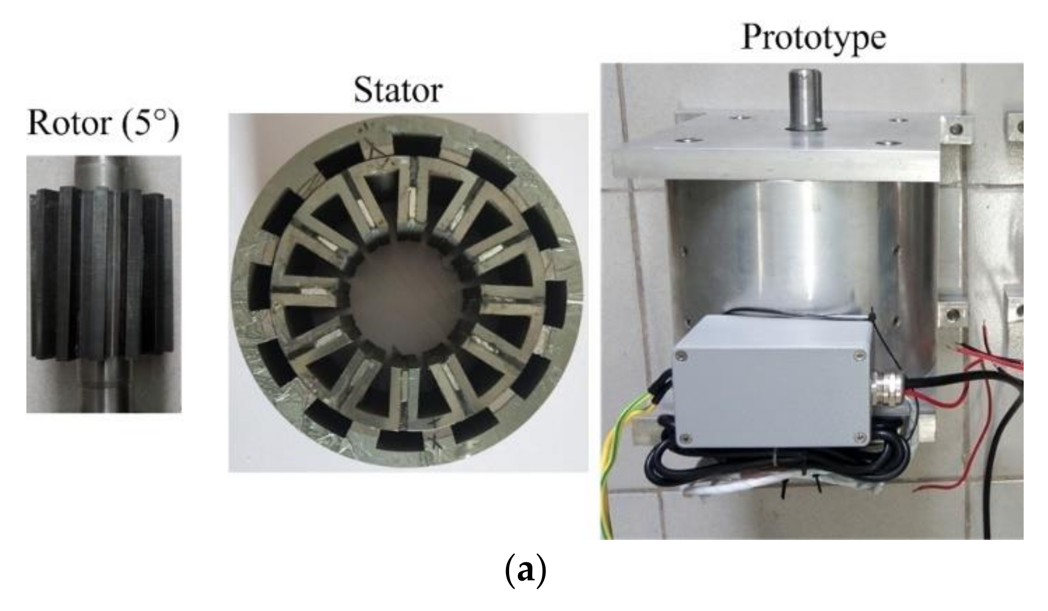
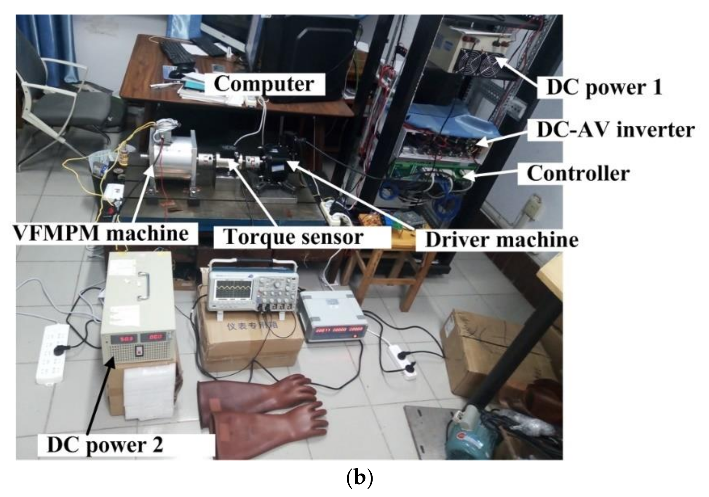
In order to further verify the validity of theory analysis, a prototype of the VFMPM machine with 12 stator slots and 14 rotor slots was manufactured and experimented on, as shown in Figure 7. The main dimension parameters of this prototype are shown in Table 1. In Figure 7b, the function of DC power 2 is to provide the electric source for the weakened flux and enhanced flux of the VFMPM machine.
4.1. Cogging Torque of the VFMPM Machine in Weakened Flux Condition
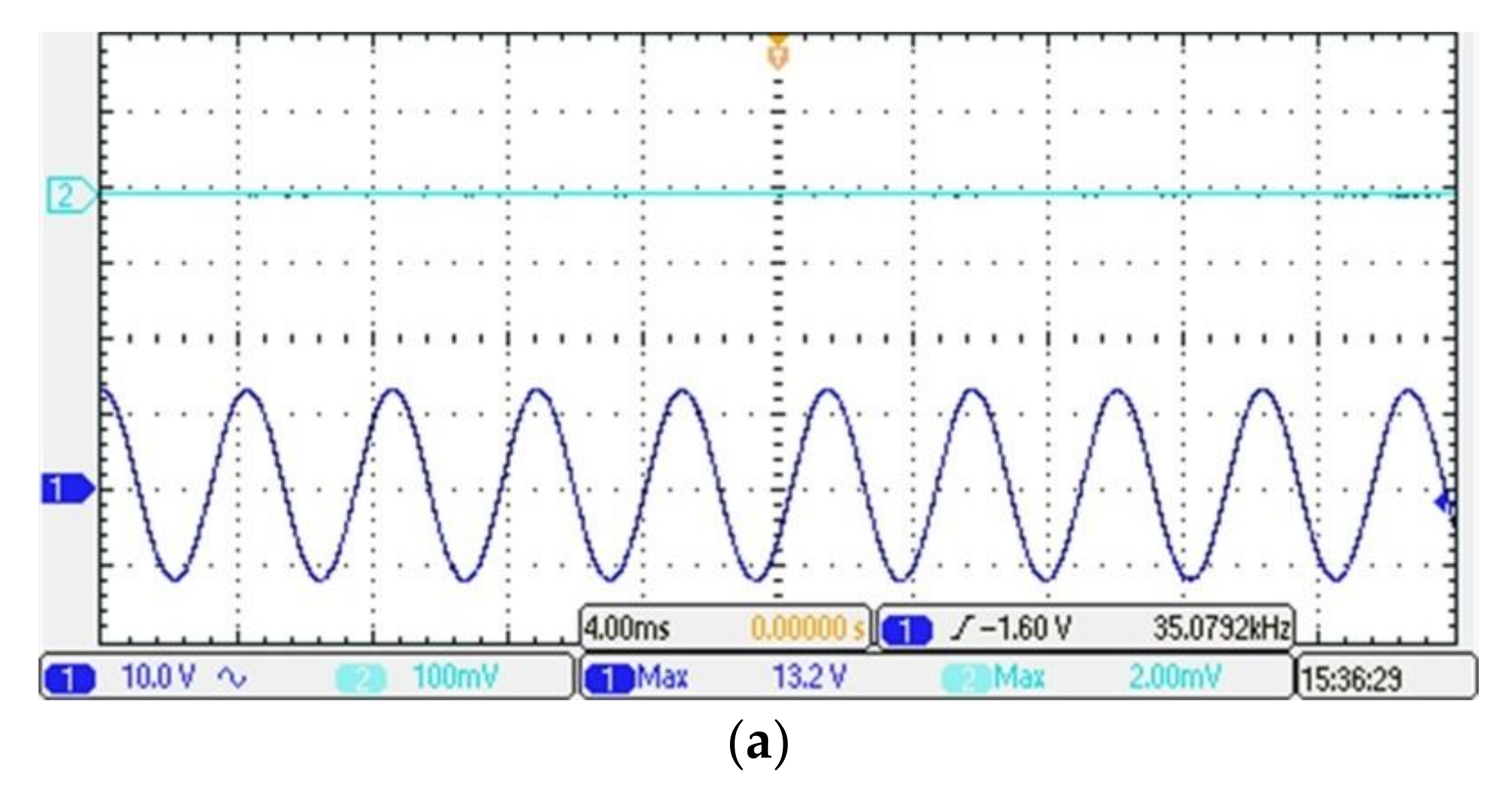
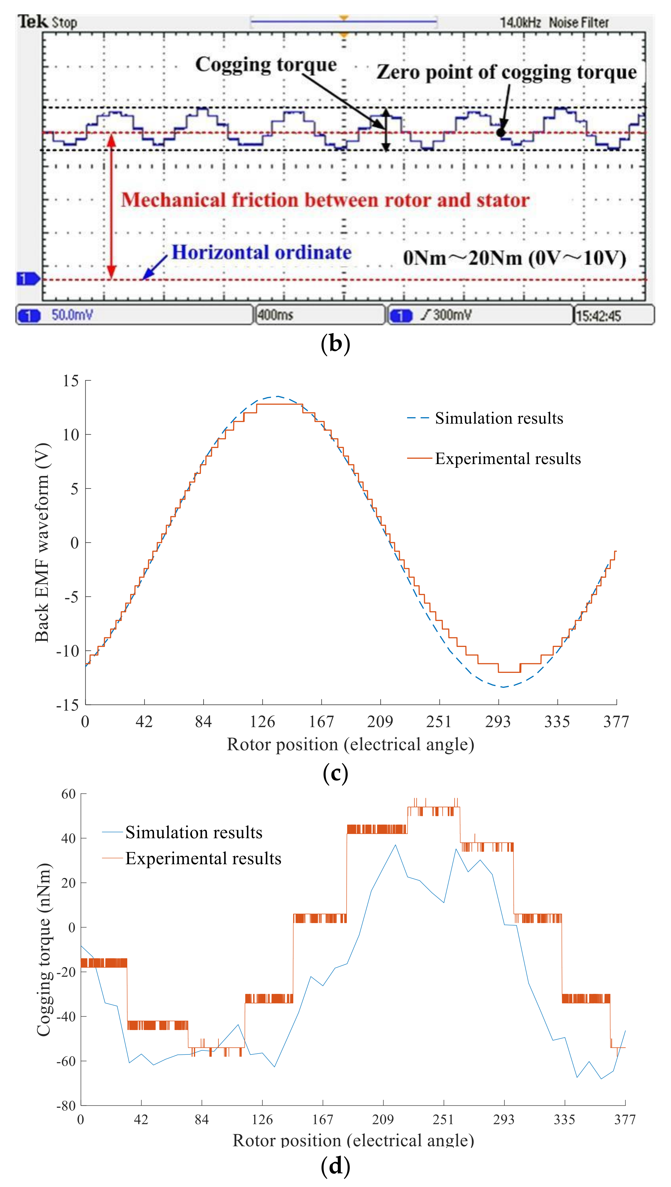
Figure 8 shows the experimental and comparison results of the VFMPM machine in weakened flux condition. Figure 8a shows the tested back EMF waveforms of the VFMPM machine, and the speed is 1000 r/min. From Figure 8a, it can be concluded that the amplitude of back EMF waveforms of the VFMPM machine is about 13.2 V, which is coincident with the simulation results (see Figure 8c). Figure 8b illustrates the tested cogging torque of the VFMPM machine by torque sensor and oscilloscope. The test scope of torque sensor is 0 Nm~20 Nm, with corresponding voltage output 0 V~10 V. Due to the need for accurate measurement of cogging torque, the speed is lower than 1000 r/min. Due to the fact that the mechanical friction occurs in the VFMPM machine, driver machine, and transmission system, the horizontal ordinate is lower than the zero point of the cogging torque. Figure 8d shows the agreement of cogging torques between experimental and simulation results. Besides, because the sampling accuracy of the torque sensor is low, the cogging torque waveforms of experimental results are presented as ladder-shaped (see Figure 8b,d).
4.2. Cogging Torque of the VFMPM Machine in Enhanced Flux Condition
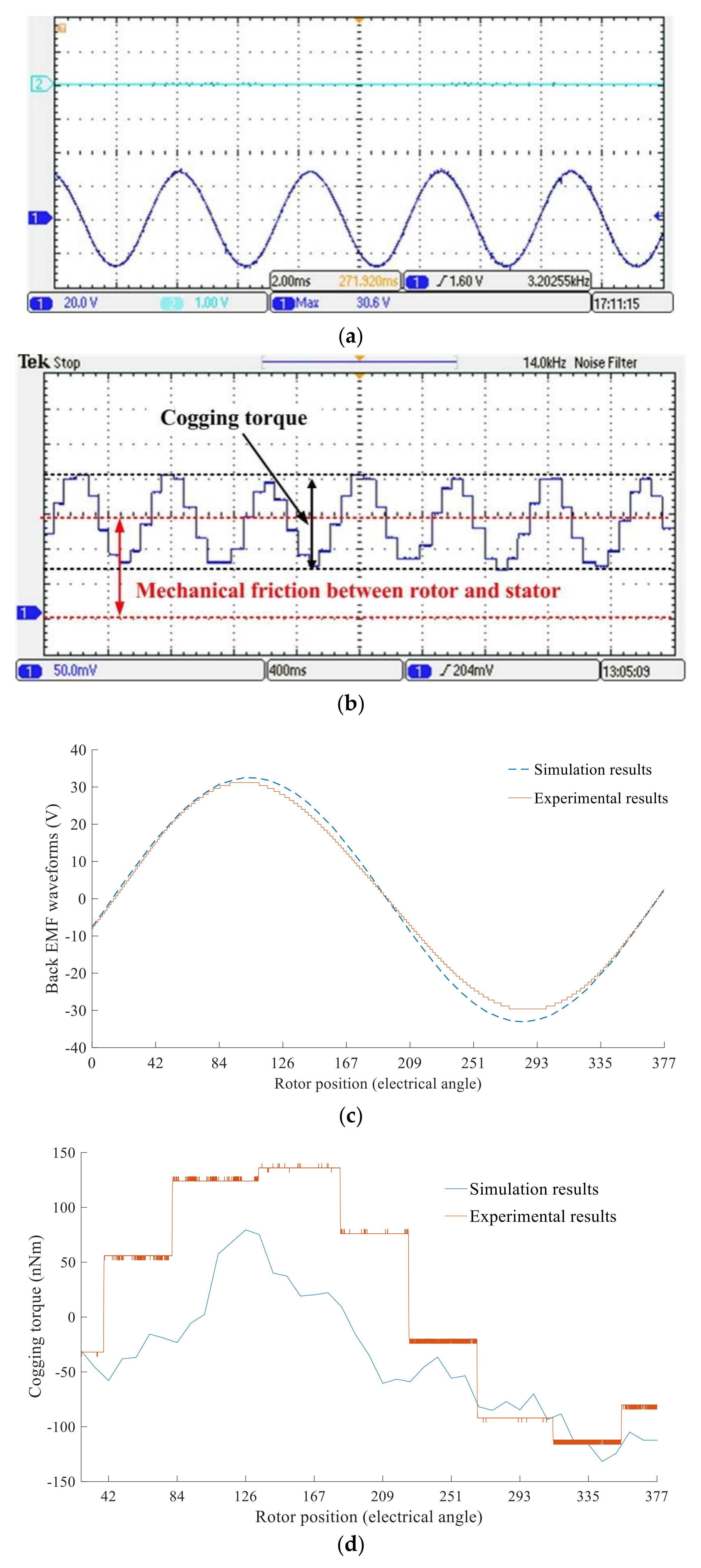
Figure 9 shows the experimental and comparison results of the VFMPM machine in enhanced flux condition. Compared with Figure 8a,b, Figure 9a,b indicate that the amplitudes of back EMF waveform and cogging torque are increased, which are mainly due to the higher air-gap flux density of the VFMPM machine (see Figure 3b). Figure 9c shows the comparison of back EMF waveforms of experimental and simulation results, and Figure 9d shows the comparison results of the cogging torque. In Figure 8c and Figure 9c, the amplitude of back EMF waveform of the experimental results is a little lower than the simulation results. The reason for this phenomenon is that some flux effects such as axial end flux effect are not considered in the simulation calculation process by software, especially in the enhanced flux situation. Figure 9d shows that the forward amplitude of the cogging torque of the experimental result is larger than the simulation one, but the peak-to-peak cogging torques of experimental and simulation results are identical.
4.3. Load Force Test of the VFMPM Machine
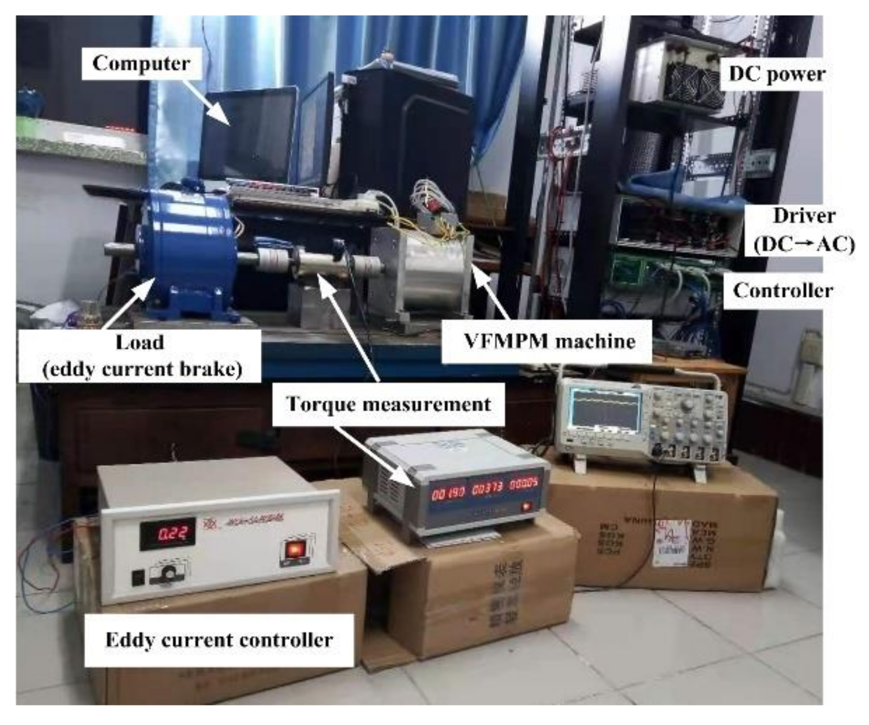
In order to further verify the cogging torque of the VFMPM machine (the no-load test results of cogging torque may be affected seriously by the mechanical friction), the cogging torque of the VFMPM machine with the load condition is tested, including the weakened flux condition and enhanced flux condition. Figure 10 shows the test rig of the cogging torque of the VFMPM machine in the load condition.
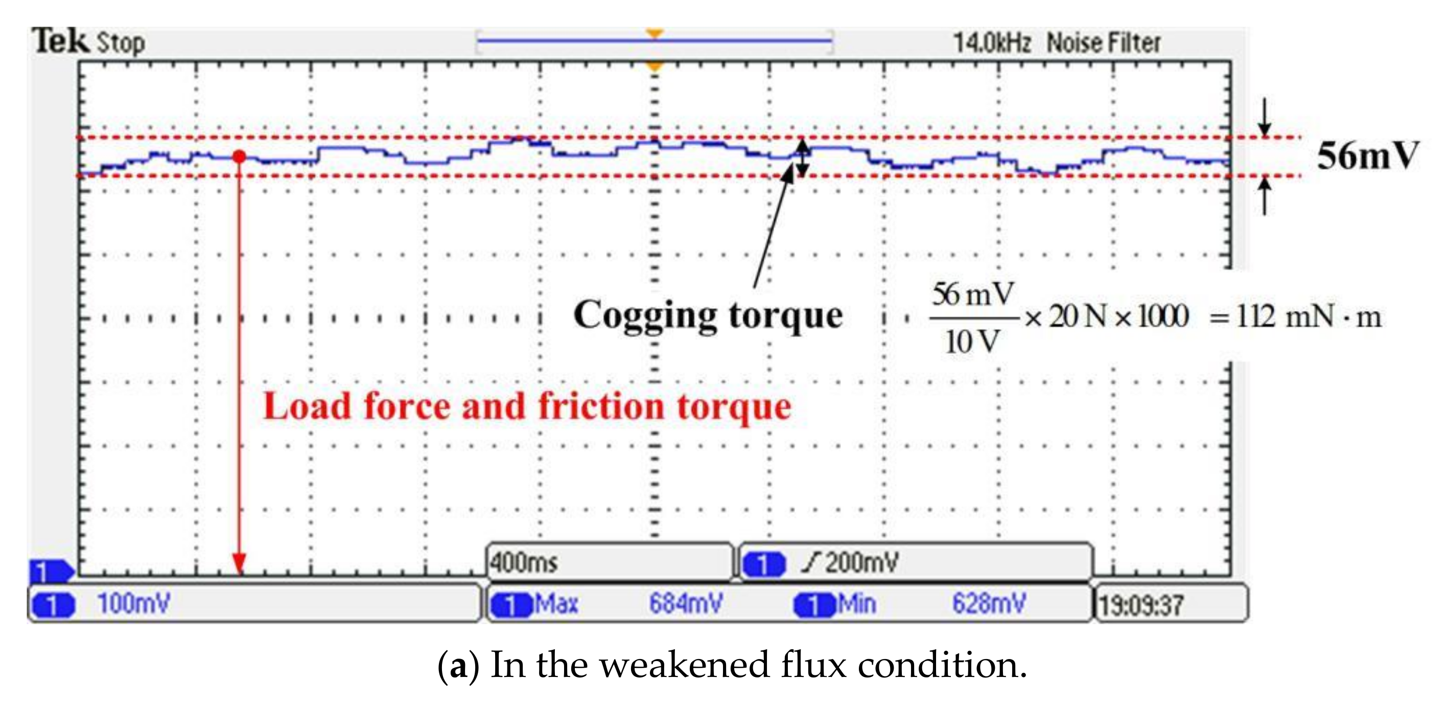
Figure 11 shows the test results of the cogging torque of the VFMPM machine in the load condition, and the load is provided by the eddy current brake (see Figure 10). For the weakened flux condition of the VFMPM machine, Figure 11a shows that the peak-to-peak cogging torque of the VFMPM machine is 112 mN·m, in accordance with the no-load test result (115 mN·m, see Figure 8d).
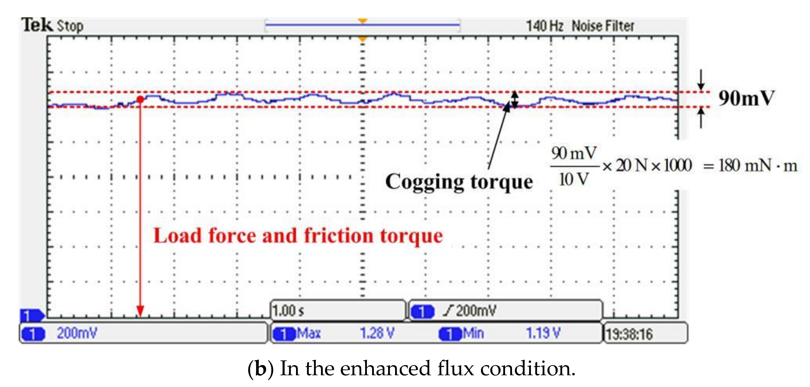
Then, the peak-to-peak cogging torque of the VFMPM machine in the enhanced flux condition is illustrated in Figure 11b, and the test result (180 mN·m) is slightly smaller than the no-load test result (240 mN·m, see Figure 9d).
Actually, the larger the load force (including the friction force), the smaller the peak-to-peak cogging torque. This phenomenon may be related to the precision of the torque measurement device, where the signal conversion from torque force (including the cogging torque and friction force in this paper) to voltage is not absolutely linear.
5. Conclusions
This paper proposed an analytical expression to uncover one method of cogging torque reduction of the VFMPM machine. Then, in order to verify the correctness of the analytical expression, a simulation model of 14 rotor slots and 12 stator slots of the VFMPM machine is established, and the back EMF waveform and cogging torque are calculated. Finally, a prototype of the VFMPM machine is manufactured and experimented on, and the experimental results further verify the effectiveness of the above theory analysis. Besides, the load force of the VFMPM machine, including the cogging torque, is also tested and analyzed in this paper, which will be a benefit for test rig improvements of the VFMPM machine in the future, such as high-precision torque sensors and so on.
Author Contributions
Conceptualization, Y.C. and Z.C.; methodology, Y.C., F.Z. and Z.C.; software, L.H.; validation, Y.C. and Z.C.; writing—original draft preparation, Y.C.; writing—review and editing, L.H. and Z.C. All authors have read and agreed to the published version of the manuscript.
Funding
This work was financially supported by the Scientific and Technological Project in Henan Province under Grant No. 212102210255 and No. 212102210516.
Data Availability Statement
Some or all data and models generated or used during the study are available in a repository or online.
Conflicts of Interest
The authors declare no conflict of interest.
Appendix A
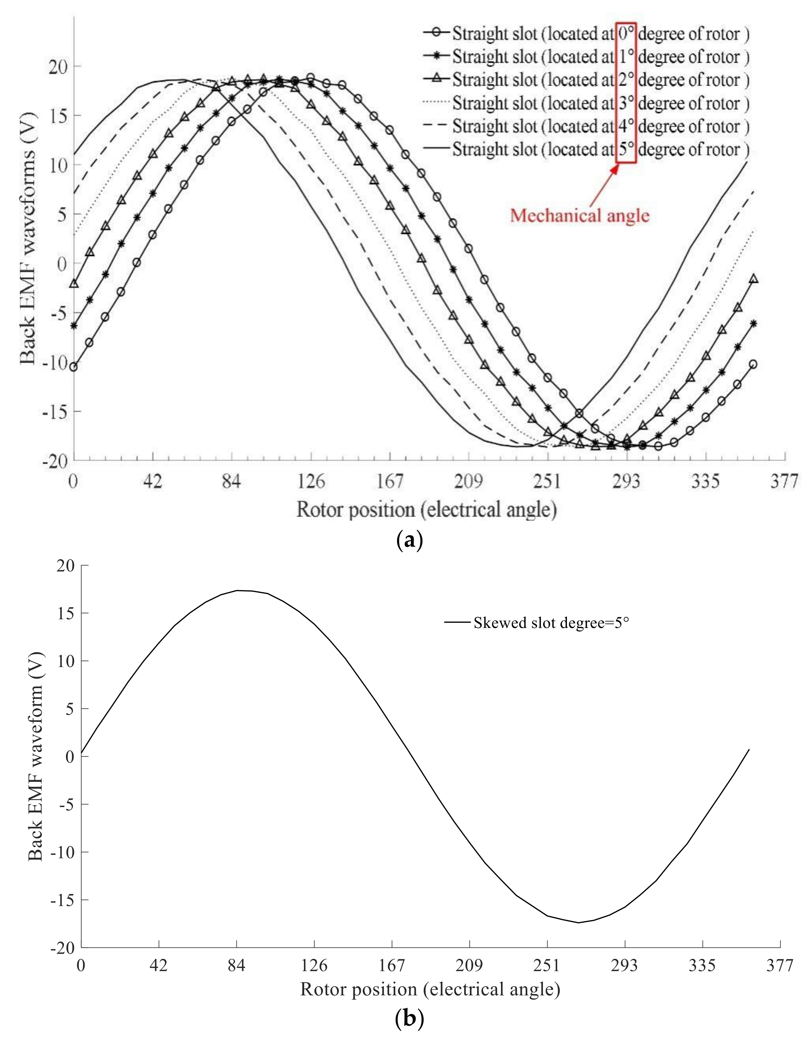
Take the case of weakened flux condition as an example, Figure A1 shows why the amplitude of back EMF waveform of rotor skewed slot type is lower than the rotor straight slot type’s. For example, if the rotor straight slots are located at the 0°, 1°, 2°, 3°, 4°, and 5° mechanical degree of rotor (see Figure A1a), the average value of back EMF waveforms of rotor straight slot (0°, 1°, 2°, 3°, 4°, and 5°) is equal to the back EMF waveform of rotor skewed slot degree = 5° (see Figure A1b). However, the amplitude of back EMF waveform in Figure A1b is 17.3 V, which is lower than the amplitude of back EMF waveform in Figure A1a (18.7 V). The reason for this phenomenon is that the phase difference exists in the rotor straight slots. Therefore, the amplitude of back EMF waveform of rotor skewed slot type is lower than the rotor straight slot type’s.
Figure A1.
The back EMF waveform of the VFMPM machine (weakened flux condition). (a) Rotor straight slot type (straight slot located at different mechanical degree of rotor); (b) Rotor skewed slot type.
Figure A1.
The back EMF waveform of the VFMPM machine (weakened flux condition). (a) Rotor straight slot type (straight slot located at different mechanical degree of rotor); (b) Rotor skewed slot type.

References
- Fang, H.; Li, D.; Qu, R.; Li, J.; Liang, D. Vibration Suppression for Flux-Switching PM Machines. IEEE Trans. Energy Convers. 2018, 33, 959–969. [Google Scholar] [CrossRef]
- Fard, J.R.; Ardebili, M. Optimal Design and Analysis of the Novel Low Cogging Torque Axial Flux-Switching Permanent-Magnet Motor. Electr. Power Compon. Syst. 2018, 46, 1330–1339. [Google Scholar] [CrossRef]
- Fei, W.; Luk, P.C.K.; Shen, J. Torque Analysis of Permanent-Magnet Flux Switching Machines with Rotor Step Skewing. IEEE Trans. Magn. 2012, 48, 2664–2673. [Google Scholar] [CrossRef] [Green Version]
- Cho, S.; Lee, D.C.; Hwang, J.; Kim, K.; Jang, G.U.; Bae, D.; Mok, H.S.; Kim, C.W. Optimal design to reduce torque ripple of IPM motor with radial based function meta-model considering design sensitivity analysis. J. Mech. Sci. Technol. 2019, 33, 3955–3961. [Google Scholar] [CrossRef]
- Angle, M.G.; Lang, J.H.; Kirtley, J.L.; Kim, S.; Otten, D. Modeling of Surface Permanent Magnet Motors with Cogging and Saturation Effects Included. IEEE Trans. Energy Convers. 2018, 33, 1604–1613. [Google Scholar] [CrossRef]
- Bu, F.; Yang, Z.; Gao, Y.; Pan, Z.; Pu, T.; Degano, M.; Gerada, C. Speed Ripple Reduction of Direct-Drive PMSM Servo System at Low-Speed Operation Using Virtual Cogging Torque Control Method. IEEE Trans. Ind. Electron. 2020, 99, 160–174. [Google Scholar] [CrossRef]
- Siyuan, M.; Jinsong, K.; Shuo, W.; Yusong, L.; Cuiwei, H. A method of thrust ripple suppression for long stator linear synchronous motor. Transp. Syst. Technol. 2018, 4, 30–44. [Google Scholar]
- Xu, D.; Jiang, X.; Tu, Y.; Li, N.; Li, Q. Investigation of cogging torque reduction for a 6/10 hybrid axial field flux-switching permanent magnet machine by harmonic field current injection. IET Electr. Power Appl. 2020, 14, 2499–2506. [Google Scholar] [CrossRef]
- Huang, W.; Hua, W.; Zhu, X.; Fan, Y.; Cheng, M. Comparison of Cogging Torque Compensation Methods for a Flux-Switching Permanent Magnet Motor by Harmonic Current Injection and Iterative Learning Control. In Proceedings of the 2020 International Conference on Electrical Machines (ICEM), Gothenburg, Sweden, 23–26 August 2020. [Google Scholar]
- Jing, L.; Pan, Y.; Wang, T.; Qu, R.; Cheng, P.T. Transient Analysis and Verification of a Magnetic Gear Integrated Permanent Magnet Brushless Machine with Halbach Arrays. IEEE J. Emerg. Sel. Top. Power Electron. 2021, 1. [Google Scholar] [CrossRef]
- Souissi, A.; Abdennadher, I.; Masmoudi, A. An Approach to Reduce the Cogging Force in Tubular Linear PM Synchronous Machines. In Proceedings of the Tenth International Conference on Ecological Vehicles & Renewable Energies, Monte Carlo, Monaco, 31 March–2 April 2015. [Google Scholar]
- Cao, R.W.; Zhang, Z.; Jin, Y.; Zhang, L. Double-sided Linear Flux-switching Permanent Magnet Motor with Yokeless Secondary and Control System. Proc. CSEE 2017, 37, 6585–6593. [Google Scholar]
- Wang, S.; Liu, C.; Wang, Y.; Lei, G.; Guo, Y.; Zhu, J. Electromagnetic Performance Analysis of Flux-Switching Permanent Magnet Tubular Machine with Hybrid Cores. China Electrotech. Soc. Trans. Electr. Mach. Syst. 2020, 4, 43–52. [Google Scholar] [CrossRef]
- Zhu, X.; Hua, W.; Wu, Z.; Huang, W.; Zhang, H.; Cheng, M. Analytical Approach for Cogging Torque Reduction in Flux-Switching Permanent Magnet Machines Based on Magnetomotive Force-Permeance Model. IEEE Trans. Ind. Electron. 2017, 65, 1965–1979. [Google Scholar] [CrossRef]
- Yang, H.; Zhu, Z.Q.; Lin, H.; Wu, D.; Hua, H.; Fang, S.; Huang, Y.K. Novel High-Performance Switched Flux Hybrid Magnet Memory Machines with Reduced Rare-Earth Magnets. IEEE Trans. Ind. Appl. 2016, 52, 3901–3915. [Google Scholar] [CrossRef]
- Chen, Z.; Cui, Y. Numerical Simulation and Experimental Validation of a Flux Switching Permanent Magnet Memory Machine. IEEE Access 2020, 8, 194904–194911. [Google Scholar] [CrossRef]
- Yang, H.; Lyu, S.; Lin, H.; Zhu, Z.Q.; Peng, F.; Zhuang, E.; Fang, S.; Huang, Y. Stepwise Magnetization Control Strategy for DC-Magnetized Memory Machine. IEEE Trans. Ind. Electron. 2019, 66, 4273–4285. [Google Scholar] [CrossRef] [Green Version]
- Su, P.; Hua, W.; Zhang, G.; Chen, Z.; Cheng, M. Analysis and evaluation of novel rotor permanent magnet flux-switching machine for EV and HEV applications. IET Electr. Power Appl. 2017, 11, 1610–1618. [Google Scholar] [CrossRef]
- Thomas, A.S.; Zhu, Z.Q.; Jewell, G.W. Proximity Loss Study in High Speed Flux-Switching Permanent Magnet Machine. IEEE Trans. Magn. 2009, 45, 4748–4751. [Google Scholar] [CrossRef]
- García-Gracia, M.; Jiménez Romero, Á.; Martín Arroyo, S. Cogging Torque Reduction Based on a New Pre-Slot Technique for a Small Wind Generator. Energies 2018, 11, 3219. [Google Scholar] [CrossRef] [Green Version]
- Zhu, X.; Hua, W.; Zhang, G. Analysis and Reduction of Cogging Torque for Flux-Switching Permanent Magnet Machines. IEEE Trans. Ind. Appl. 2019, 55, 5854–5864. [Google Scholar] [CrossRef]
Figure 1.
The structure of the VFMPM machine.

Figure 2.
The continuous skewed slot structure of rotor core of the VFMPM machine.

Figure 3.
Magnetic potential distribution of the VFMPM machine. (a) Weakened flux condition; (b) Enhanced flux condition.
Figure 3.
Magnetic potential distribution of the VFMPM machine. (a) Weakened flux condition; (b) Enhanced flux condition.

Figure 4.
Enhanced flux process of VFMPM machine.

Figure 5.
The comparison of back EMF waveform and cogging torque of the VFMPM machine in weakened flux condition. (a) Back EMF waveform; (b) Cogging torque.
Figure 5.
The comparison of back EMF waveform and cogging torque of the VFMPM machine in weakened flux condition. (a) Back EMF waveform; (b) Cogging torque.

Figure 6.
The comparison of back EMF waveform and cogging torque of the VFMPM machine in enhanced flux condition. (a) Back EMF waveform; (b) Cogging torque.
Figure 6.
The comparison of back EMF waveform and cogging torque of the VFMPM machine in enhanced flux condition. (a) Back EMF waveform; (b) Cogging torque.


Figure 7.
The prototype of the VFMPM machine and test rig. (a) VFMPM machine; (b) Test rig.


Figure 8.
The experimental and comparison results of the VFMPM machine in weakened flux condition. (a) Experimental results of back EMF waveforms; (b) Experimental results of cogging torque; (c) Comparison of back EMF waveforms; (d) Comparison of cogging torques.
Figure 8.
The experimental and comparison results of the VFMPM machine in weakened flux condition. (a) Experimental results of back EMF waveforms; (b) Experimental results of cogging torque; (c) Comparison of back EMF waveforms; (d) Comparison of cogging torques.


Figure 9.
The experimental and comparison results of the VFMPM machine in enhanced flux condition. (a) Experimental results of back EMF waveforms; (b) Experimental results of cogging torque; (c) Comparison of back EMF waveforms; (d) Comparison of cogging torques.
Figure 9.
The experimental and comparison results of the VFMPM machine in enhanced flux condition. (a) Experimental results of back EMF waveforms; (b) Experimental results of cogging torque; (c) Comparison of back EMF waveforms; (d) Comparison of cogging torques.

Figure 10.
Test rig of cogging torque of the VFMPM machine in the load condition.

Figure 11.
Test results of cogging torque of the VFMPM machine in the load condition. (a) In the weakened flux condition; (b) In the enhanced flux condition.
Figure 11.
Test results of cogging torque of the VFMPM machine in the load condition. (a) In the weakened flux condition; (b) In the enhanced flux condition.


Table 1.
The dimension parameters of the VFMPM machine.
| Descriptions | VFMPM | |
|---|---|---|
| Stator | Outer radius | 79.2 mm |
| Inner radius | 35 mm | |
| Tooth width | 8.22 deg | |
| Slots | 12 | |
| Rotor | Outer radius | 34.5 mm |
| Tooth width | 10 deg | |
| Poles | 14 | |
| NdFeB35 | Thick | 3.5 mm |
| Length | 15 mm | |
| LNG52 | Length | 12 mm |
| Thick | 5 mm | |
| Others | Air gap wide | 0.5 mm |
| Turns of armature winding per phase | 140 | |
| Turns of field regulating winding per LNG52 | 60 | |
| Axial length | 75 mm |
Publisher’s Note: MDPI stays neutral with regard to jurisdictional claims in published maps and institutional affiliations. |
© 2021 by the authors. Licensee MDPI, Basel, Switzerland. This article is an open access article distributed under the terms and conditions of the Creative Commons Attribution (CC BY) license (https://creativecommons.org/licenses/by/4.0/).
Share and Cite
MDPI and ACS Style
Cui, Y.; Zhang, F.; Huang, L.; Chen, Z. Analysis and Verification of a Cogging Torque Reduction Method for Variable Flux Memory Permanent Magnet Machine. Electronics 2021, 10, 1913. https://doi.org/10.3390/electronics10161913
AMA Style
Cui Y, Zhang F, Huang L, Chen Z. Analysis and Verification of a Cogging Torque Reduction Method for Variable Flux Memory Permanent Magnet Machine. Electronics. 2021; 10(16):1913. https://doi.org/10.3390/electronics10161913
Chicago/Turabian StyleCui, Yingjie, Fei Zhang, Lei Huang, and Zhongxian Chen. 2021. "Analysis and Verification of a Cogging Torque Reduction Method for Variable Flux Memory Permanent Magnet Machine" Electronics 10, no. 16: 1913. https://doi.org/10.3390/electronics10161913
Note that from the first issue of 2016, this journal uses article numbers instead of page numbers. See further details here.