
Improving the Efficiency of Partially Shaded Photovoltaic Modules without Bypass Diodes


1
Electrical, Computer and Biomedical Engineering Department, Abu Dhabi University, Abu Dhabi 59911, United Arab Emirates
2
Electrical Engineering Department, Faculty of Engineering, The Hashemite University, Zarqa 13115, Jordan
3
Power, Electrical and Control Group, Department of Engineering and Mathematics, Sheffield Hallam University, Sheffield S1 1WB, UK
*
Authors to whom correspondence should be addressed.
Electronics 2021, 10(9), 1046; https://doi.org/10.3390/electronics10091046
Submission received: 8 April 2021
/
Revised: 22 April 2021
/
Accepted: 24 April 2021
/
Published: 29 April 2021
(This article belongs to the Section Semiconductor Devices)
Abstract
:Photovoltaic (PV) modules comprise bypass diodes to limit hotspot formation. However, they suffer from performance reduction in the presence of partial shading. This paper proposes external circuitry to control the connection type (series/parallel) of the PV cells through a pair of on/off switches resulting in three different operation modes. Mode 1 represents the typical 36 series-connected cells, while mode 2 represents two parallel-connected strings, and mode 3 maximizes the output current where the four strings are connected in parallel. The added values of the approach are that (1) the output current of the PV module can be increased without the need for a buck-boost converter and (2) the partial shading has less impact on the output power than the adoption of bypass diodes. This work shows that simulating three monocrystalline PV modules (120 W, 200 W, and 241 W), consisting of 36, 60, and 72 series-connected cells, lose about 74% when one cell has 80% shading in the absence of bypass diodes. The application of a bypass diode for each pair of strings in the PV module improves this decrease to 61.89%, 40.66%, and 39.47%, respectively. According to our proposed approach, this power loss can be significantly decreased to 19.59%, 50%, and 50.01% for the three PV modules, respectively, representing more than a 42% improvement compared to bypass diodes.
1. Introduction
Recently, renewable energy resources have gained extreme attention because of environmental concerns. Of the renewable sources, photovoltaics (PVs) have received considerable focus because of the development of their fabrication technologies. PV modules consist of electrically interconnected PV cells. The modules are encapsulated to protect the cells from environmental conditions (e.g., water vapor, water, and mechanical damage). The PV modules can then be connected in series and/or parallel to supply the load demand. It is a major advantage of PV modules that they can be considered highly modular, and by proper scaling, and they can be expected to provide adequate power for a wide range of loads [1]. The PV modules can be utilized for stand-alone and grid-tied systems to produce an output power ranging from micro-watts to megawatts depending on their applications, such as in communications, electric vehicles, solar homes, and satellites [2]. The technological development of photovoltaic (PV) cells is identified in [3] by analyzing all the patents issued in the field of photovoltaics. PV modules have become safe and reliable power supplies for a lifetime of 20 to 30 years. Their performance is typically rated in the standard test conditions (STC) (i.e., T = 300 K, solar irradiance = 1 kW/m, and Air Mass 1.5). The deviation between the real operating conditions and the STC ratings results in a deviation in the expected PV performance. Some researchers have proposed the combined detection and diagnosis of degradation, open circuit, and partial shading where the PV module’s current-voltage curve is an important index to characterize the performance of PV modules [4,5,6,7,8,9,10,11,12,13].
The open-circuit voltage of the PV modules decreases linearly (and depends on the temperature coefficient of ) as the ambient temperature increases, while the short-circuit current increases linearly as the incident solar irradiance increases [14,15]. One of the major challenges for PV modules is the partial shading, where the photo-generated current of the shaded cell decreases compared to unshaded series-connected cells. Without the bypass diode present, the shaded PV cells will be reverse-biased, resulting in potentially damaging reverse breakdown voltage and hotspot failure. The impact of partial shading is clear in the distortion of the current–voltage curve. PV modules are partially shaded when the cells share non-uniform irradiance due to the passing of a cloud or surrounding buildings and trees [16]. The partial shading can lead to the reduction of the PV module’s maximum power point (MPP) and cause the formation of hotspots [17,18,19,20,21]. The effect of shading is different, as the effect for monocrystalline modules is more noticeable than for thin-film PV modules [20]. The monocrystalline modules show better performance compared to the thin films and polycrystalline technologies. Therefore, this work focuses on the monocrystalline PV modules. Adopting a bypass diode limits hotspot effects in parallel with typical 18–24 series-connected PV cells to reduce the maximum reverse voltage across the shaded PV cells and therefore increase the overall short-circuit current and the open-circuit voltage [22,23,24,25]. Therefore, the bypass diodes have been widely utilized in PV modules to maximize their output under partially shaded conditions [26,27].
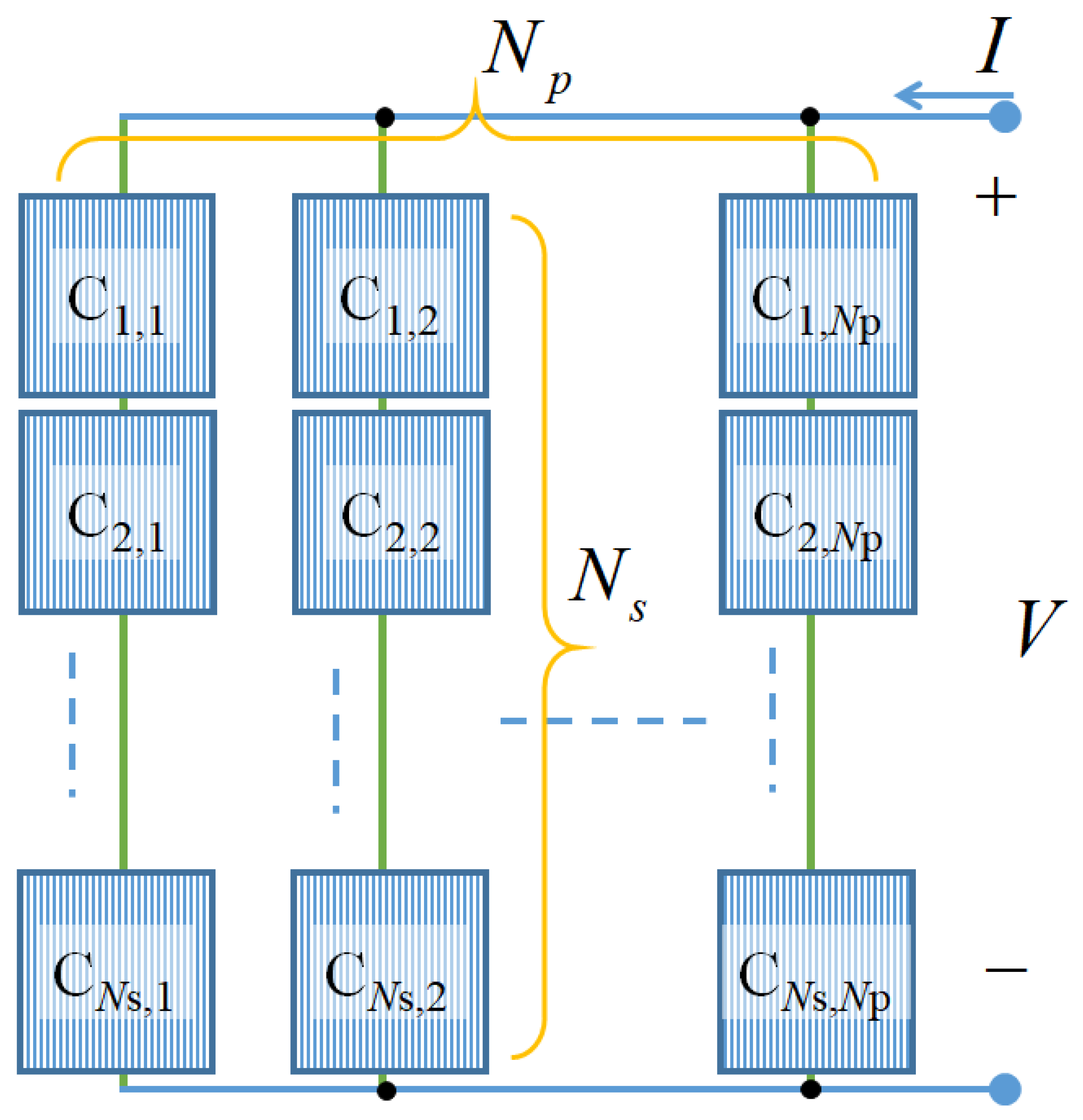
The existing photovoltaic (PV) modules comprise series-connected cells where every module is rated based on its DC output power under the standard test conditions (STC), typically with a value of 100–320 W [28]. Figure 1 shows series and parallel combinations of PV cells; typically, = 36 and = 1 for the 120 W, = 60 and = 1 for the 200 W, and = 72 and = 1 for the 240 W PV modules.
The PV module’s performance is extracted from its current–voltage characteristics, which can be expressed as a function of the PV cells’ parameters and their interconnections, as in [29,30,31].
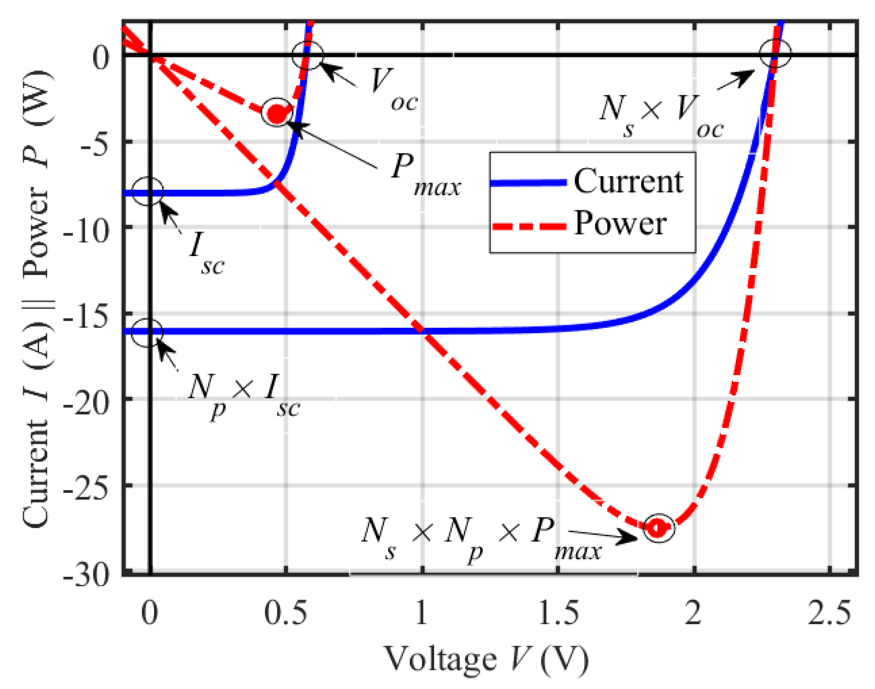
where is the number of series-connected cells and is the number of parallel-connected strings. is the reverse-saturation current, is the ideality factor, and is the short-circuit current. The term is the thermal voltage and equals 25.9 mV at T = 300 K. The parasitic resistances and reduce the cell performance. The series resistance prescribes the electrical losses in the bulk of the semiconductor material and all its metallic contacts in addition to the contact resistance between the semiconductor and the contacts. The parallel resistance prescribes the leakage at the edge of the cell or any extended defects through the pn-junction. Figure 2 shows the current and power–voltage characteristics of a single PV cell and the corresponding PV module comprising identical (same values of , , and ) PV cells. The PV module’s open-circuit voltage, short-circuit current and maximum power are , , , , and , , respectively. An important point to mention is that this study used one PV module. The same concept of choosing parallel and series connections of PV modules can be applied on a larger scale, which will be future work.
2. Methodology
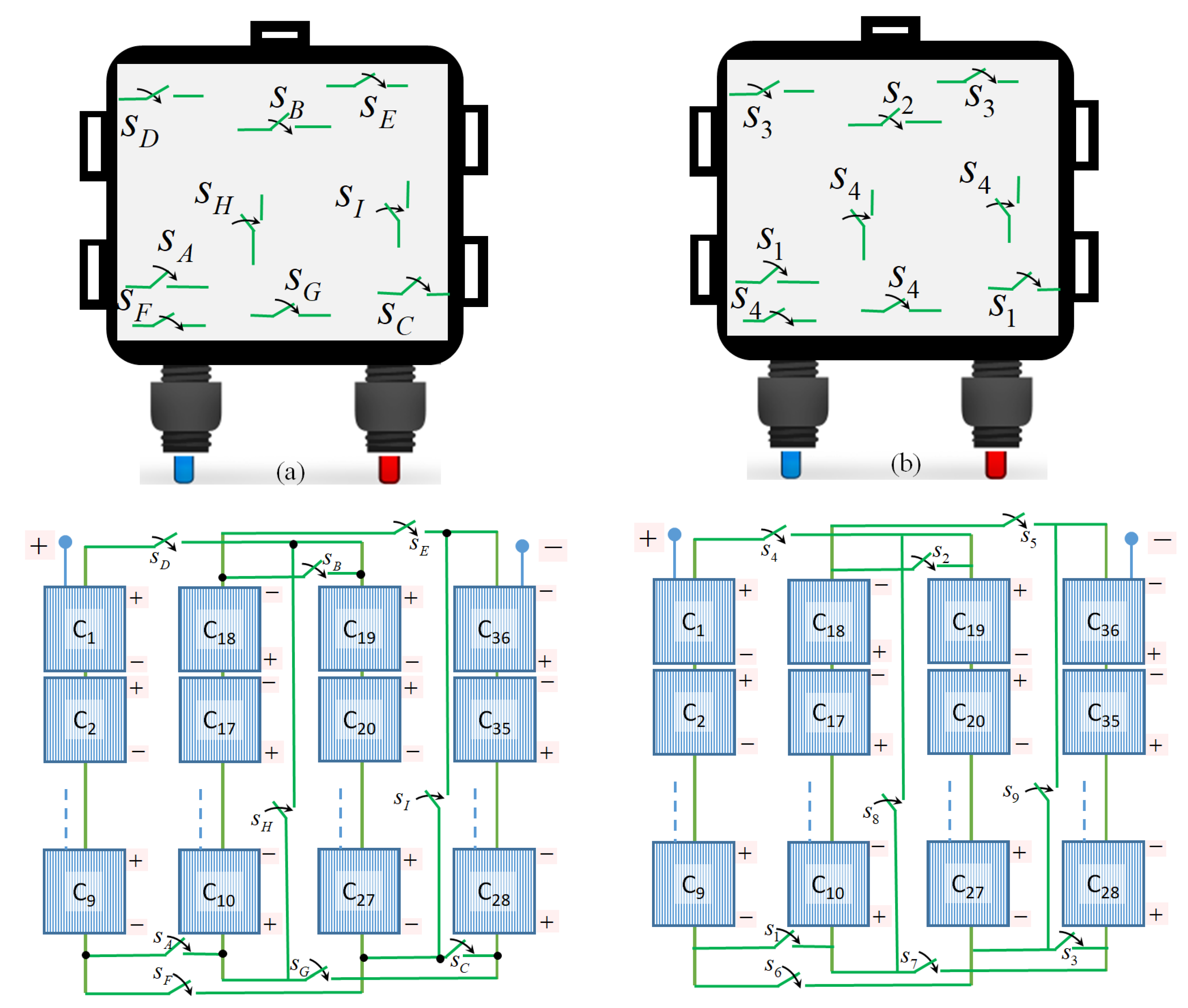
The current–voltage characteristics at standard test conditions allow the parameters of the PV module to be determined. In this work, we simulated typical PV modules consisting of 36, 60, and 72 series-connected PV cells. Therefore, the cells’ voltages were additive, while the current depended on any possible shaded PV cells’ performance. The current through the series-connected PV cells was the current capability of the lowest current-delivering PV cell, as the weakest solar cell cannot support a higher current at a common illumination level. Power available from higher performance cells was lost while trying to push current through the lower performing cells [32,33]. To vary/regulate the output electrical parameters, switching buck-boost converters can be employed and can transfer the harvested energy to storage [34]. In this work, no converters were used; these were replaced by controllable switches as explained below. To simplify the concept, we began with the 36-cell PV module and compared the performance of this typical module in the presence of two bypass diodes with the same module’s performance following our proposed method. In this work, we modified the existing junction box of a PV module by implementing nine switches (labeled … ) to control the PV cells’ interconnections, as shown in Figure 3a. It was found in this work that some switches needed to be operated simultaneously. Figure 3b replaces the notations of the switches to clarify the proposed concept as → and , S2 →, →, and , → and . Therefore, we can claim that the nine switches were replaced with four different switches to maintain the same operation at lower system complexity. The actual connections of the switches are depicted in the same figure.
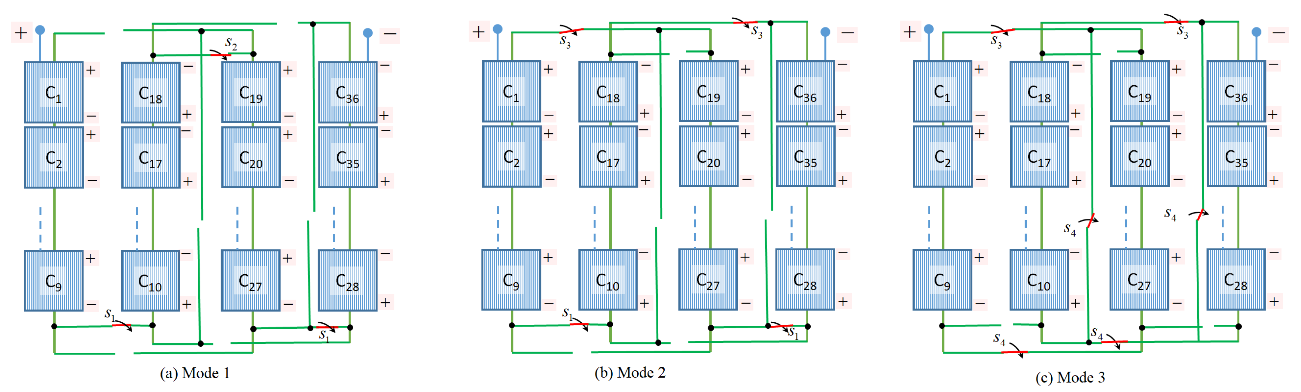
When the switches and were closed, this mode was called “Mode 1”, where the 36 PV cells were connected in series. Mode 2 occurred when the switches and were closed and where the PV module was divided into two parallel strings, each comprising 18 series-connected PV cells. To maximize the current more, Mode 3 was selected where the switches and were closed, resulting in four parallel strings, each comprising nine series-connected PV cells. Figure 4 shows the three different modes of operations, where the voltage and the current could be scaled based on the load’s electrical needs. A single PV module with variable output current is an alternative solution to connecting several modules in parallel when a higher current is needed. The modes and their corresponding switches’ connections are summarized in Table 1. The typical PV modules have their PV cells connected according to Mode 1. Since the typical modules have all the PV cells connected in series, the overall module current is dominated by the shaded cells. To overcome this scenario, Mode 2 and Mode 3 were chosen to create two and four parallel strings, respectively, to protect the module from any possible hotspot formation.
Our proposed PV modules had the advantage of controlling the PV cells’ internal connections to vary the performance of the PV module. Eighty percent shading was applied to one of the cells () to validate our proposed PV module’s potential. The cases were carefully selected to start from normal system operation (without any shading) and apply the given modes above to assess the PV modules’ operation when one cell was 80% shaded.
Figure 5 depicts the cases used in this research. The analysis begins with the case where the connections of the PV cells are according to Mode 1 (default), and no PV cell is shaded. Figure 5b,c shows different cases for shading with and without the adoption of bypass diodes to simulate the effect of shading. In Figure 5d,e, the two PV modes of operation (mode 2 and mode 3) were applied to simulate the same shading effect to compare the power losses.
3. Results and Discussion
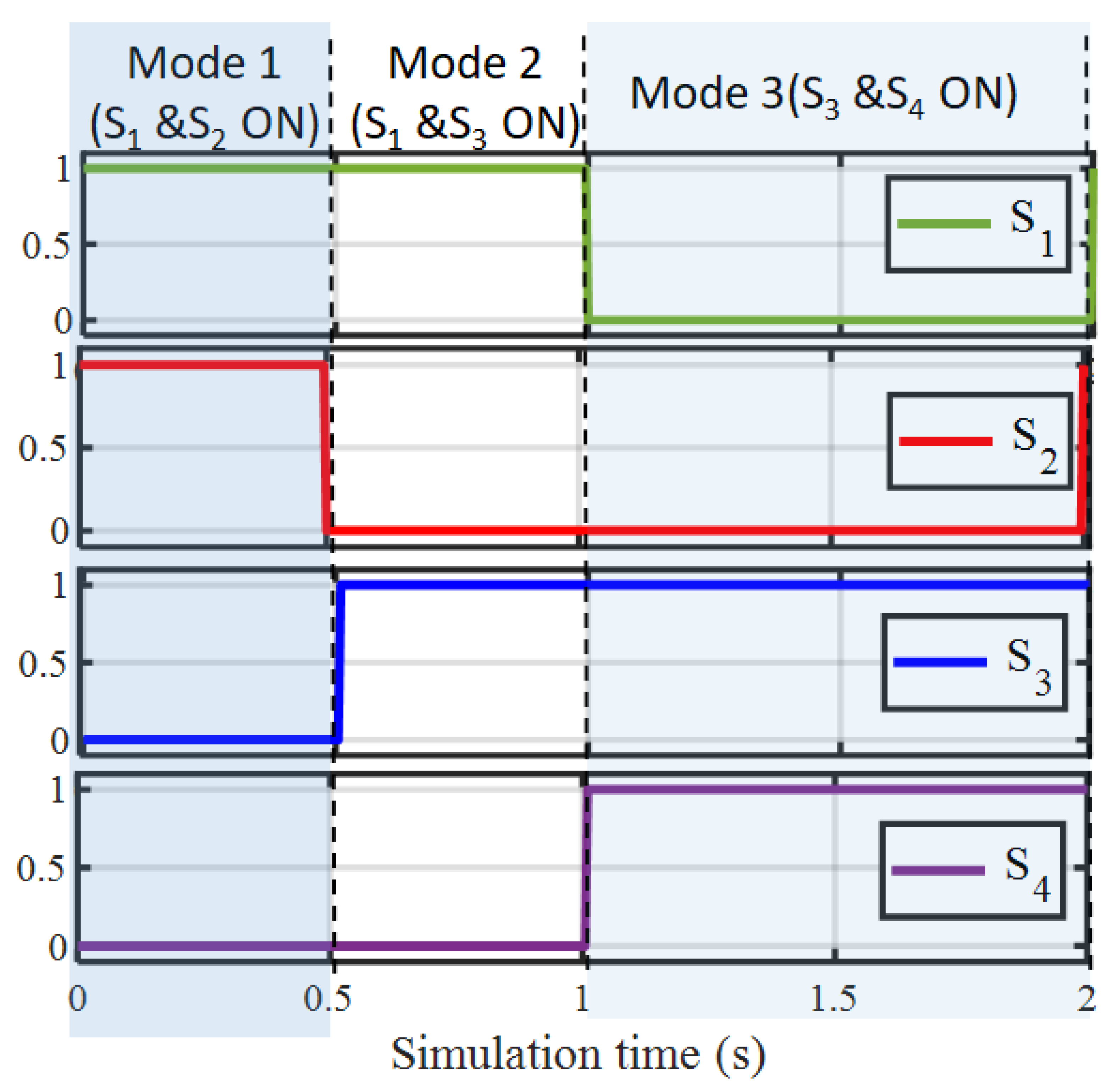
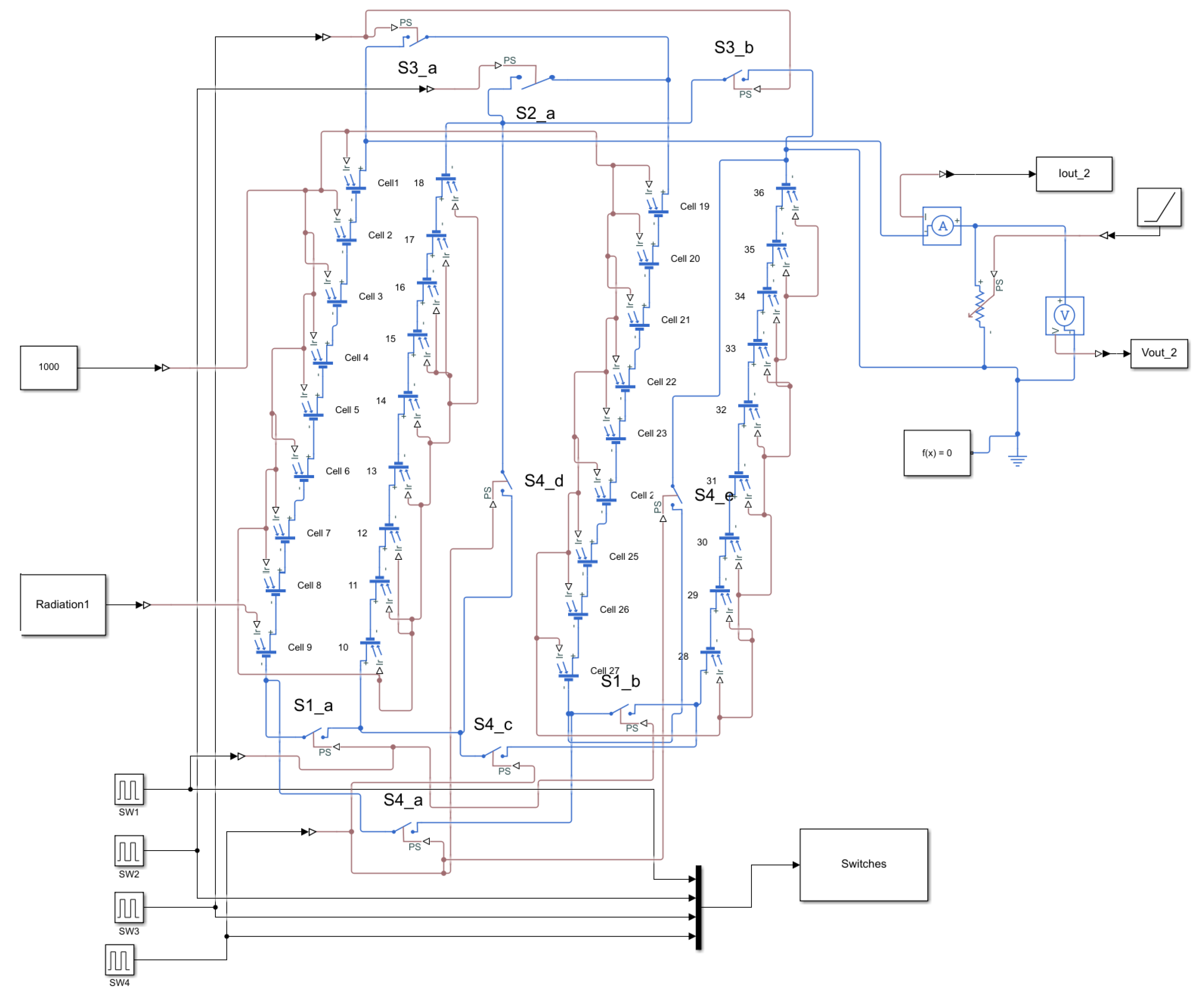
The proposed PV modules in this article were modeled based on the switches’ states that connected/disconnected the PV strings. Therefore, parallel and/or series strings could be formed, resulting in a wide range of voltage and current values. When the strings were connected in series, a higher voltage was achieved, while when they were connected in parallel, a higher current was achieved. Using this technique, the current and the voltage could be controlled to meet the load requirement. For each scenario of the string connections, we tracked the current–voltage characteristics of the proposed PV modules and compared their performance with the conventional modules with and without shading effects. MATLAB Simulink® was used in this article to prove the concept of the proposed model of the PV modules. From the current–voltage characteristics, the open-circuit voltage, the short-circuit current, and the maximum-power point values were extracted. The switches were controlled as explained in Table 1, and their instantaneous states are depicted in Figure 6. Passive switches were used in this work to mitigate the risk of any circuit failure. In fact, the four switches could be simplified into two single-pole double-throw (SPDT) switches. The switches and complemented the corresponding states of the switches S4 and S3, respectively. Therefore, and could be combined as one SPDT switch, while the switches and could be combined as a second SPDT switch. At each time slot, the states of the switches determined which cells were to be connected. Figure 7 shows the complete model, consisting of 36 identical cells except cell 9, which was 80% shaded. The simulation of the PV module for the five cases is depicted in Figure 8, which was done to extract the corresponding electrical parameters from the current–voltage characteristics in every case. As a figure of merit to compare the power losses due to shading, we assumed the power in case (a) as a reference for the calculation power losses as follows:
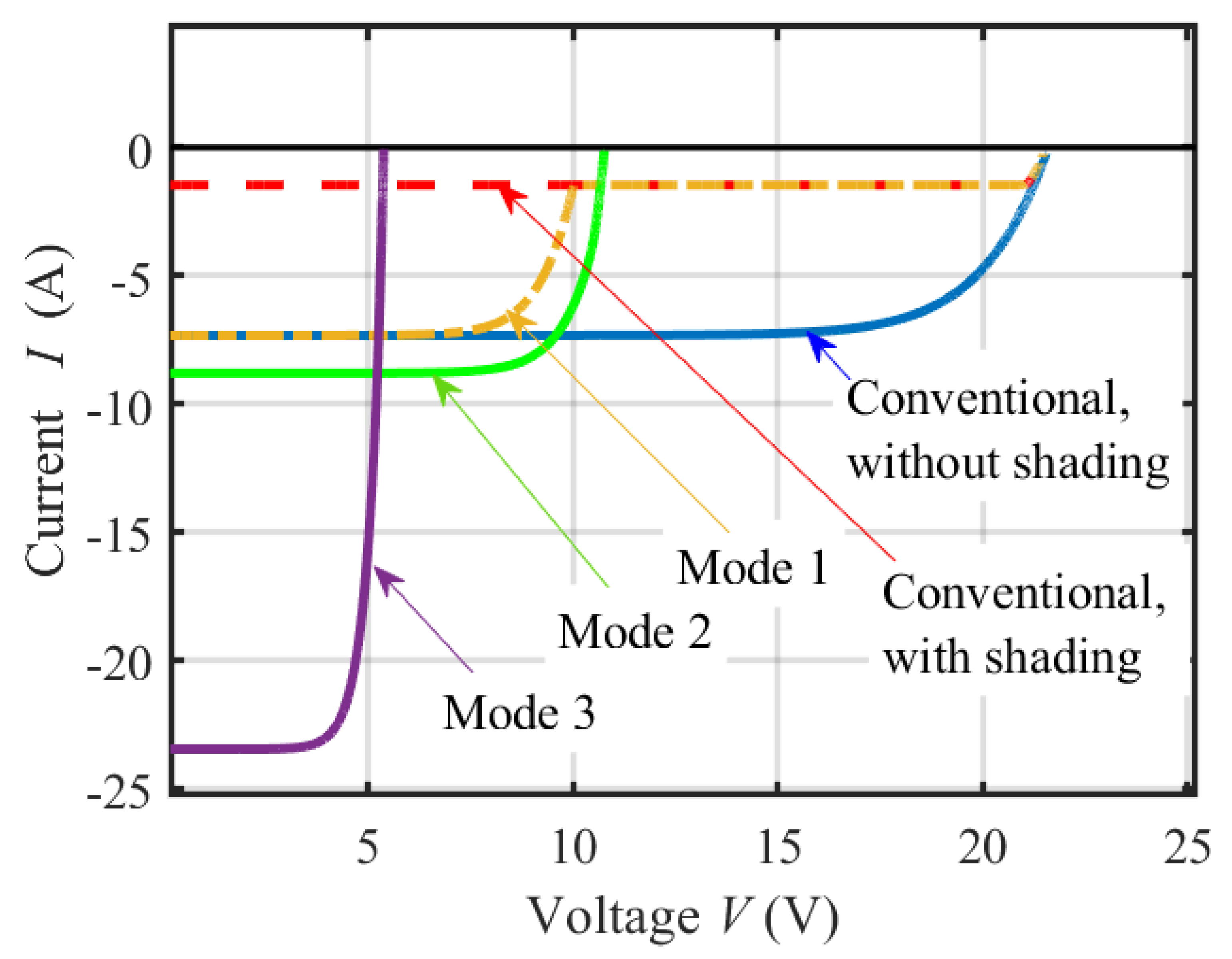
Table 2 depicts the calculations of , , and for each of the five cases. It shows that the PV modules generated a maximum power of 120.6 W/200.98 W/241.19 W for the 36/60/72-cell modules, respectively. Shading one cell reduced the power to 30.69 W/51.44 W/61.82 W for the aforementioned modules, which could be increased to 45.96 W/119.27 W/45.99 W, respectively with the help of bypass diodes. The output power could be further improved by selecting mode 2, where the power was able to reach 73.41 W/139.21 W/167.03 W, which could further be increased by adopting mode 3. When one of the cells was shaded, it was better to minimize the number of series-connected cells to this shaded cell. This was accomplished in mode 2, where the given PV module was divided into parallel strings, each with 18 (for the 36-cell modules), 20 (for the 60-cell modules), or 24 (for the 72-cell modules) series-connected cells, while mode 3 connected all the strings in parallel, each with 9, 10, or 12 series-connected cells, resulting in higher current values.
4. Conclusions
This work introduced a smart assembly for PV cells whose interconnections are controlled by several switches inside a junction box located at the proposed PV modules’ back-side. The first advantage of the proposed PV modules over the existing modules is that the output current and voltage can be varied without building a buck-boost converter circuit or introducing other modules in parallel to increase the current. The new consideration in this paper is that the partial shading effect of a PV cell has less impact on the PV module’s electrical output power than the use of bypass diodes. This work showed that simulating three monocrystalline PV modules (120 W, 200 W, and 241 W), consisting of 36, 60, and 72 series-connected cells resulted in a loss of about 74% when one cell has 80% shading in the absence of bypass diodes. According to this research, this power loss can be significantly decreased to 19.59%, 50%, and 50.01% for the three PV modules, respectively, representing more than a 42% improvement compared to bypass diodes. This work proved the concept of applying two SPDT switches to improve the efficiency of standard photovoltaic modules.
Author Contributions
A.A.T. conceived the main idea of the work and performed the calculations of the output characteristics of the PV modules. M.A. and M.G. revised the manuscript and recommended the inclusion of an example of a shading scenario for one of the PV cells. They also validated all the calculations presented in the manuscript. All authors have read and agreed to the published version of the manuscript.
Funding
This research was funded by the Office of Research and Sponsored Programs in Abu Dhabi University with grant number 19300473.
Conflicts of Interest
The authors declare no conflict of interest.
References
- Costica, N.; Gabriel, C.; Cuciureanu, D.; Guoqiang, Z.; Dong, H.T. Numerical Analysis of a Real Photovoltaic Module with Various Parameters. Model. Simul. Eng. 2018, 2018, 1–12. [Google Scholar]
- Parida, B.; Iniyan, S. A review of solar photovoltaic technologies. Renew. Sustain. Energy Rev. 2011, 15, 1625–1636. [Google Scholar] [CrossRef]
- Gonçalves, P.; Sampaioa, V.; Orestes, M.; Gonzáleza, A.; Monteirode, R.; Marllen, V.; Teixeirados, A.; José, S.; Toledob, C.; Paulo, J.; et al. Photovoltaic technologies: Mapping from patent analysis. Renew. Sustain. Energy Rev. 2018, 93, 215–224. [Google Scholar]
- Ram, J.P.; Manghani, H.; Pillai, D.S.; Babu, T.S.; Miyatake, M.; Rajasekar, N. Analysis on solar PV emulators: A review. Renew. Sustain. Energy Rev. 2018, 81, 149–160. [Google Scholar] [CrossRef]
- Chou, K.Y.; Yang, S.; Chen, Y. Maximum Power Point Tracking of Photovoltaic System Based on Reinforcement Learning. Sensors 2019, 19, 5054. [Google Scholar] [CrossRef] [PubMed] [Green Version]
- Pozo, B.; Garate, J.; Araujo, J.; Ferreiro, S. Photovoltaic Energy Harvesting System Adapted for Different Environmental Operation Conditions: Analysis, Modeling, Simulation and Selection of Device. Sensors 2019, 19, 1578. [Google Scholar] [CrossRef] [PubMed] [Green Version]
- Antolín, D.; Medrano, N.; Calvo, B.; Martínez, P.A. A Compact Energy Harvesting System for Outdoor Wireless Sensor Nodes Based on a Low-Cost In Situ Photovoltaic Panel Characterization-Modelling Unit. Sensors 2017, 17, 1794. [Google Scholar] [CrossRef] [PubMed] [Green Version]
- Dhimish, M.; Holmes, V.; Mehrdadi, B.; Dales, M.; Mather, P. Photovoltaic fault detection algorithm based on theoretical curves modeling and fuzzy classification system. Energy 2017, 140, 279–290. [Google Scholar] [CrossRef]
- Chen, Z.; Wu, L.; Cheng, S.; Lin, P.; Wu, Y.; Lin, W. Intelligent fault diagnosis of photovoltaic arrays based on optimized kernel extreme learning machine and I-V characteristics. Appl. Energy 2017, 204, 912–931. [Google Scholar] [CrossRef]
- Chen, Z.; Han, F.; Wu, L.; Yu, J.; Cheng, S.; Lin, P.; Chen, H. Random forest based intelligent fault diagnosis for PV arrays using array voltage and string currents. Energy Convers. Manag. 2018, 178, 250–264. [Google Scholar] [CrossRef]
- Wu, L.; Chen, Z.; Long, C.; Cheng, S.; Lin, P.; Chen, Y.; Chen, H. Parameter extraction of photovoltaic models from measured I–V characteristics curves using a hybrid trust-region reflective algorithms. Appl. Energy 2018, 232, 36–53. [Google Scholar] [CrossRef]
- Dolara, A.; Lazaroiu, G.C.; Leva, S.; Manzolini, G. Experimental investigation of partial shading scenarios on PV (photovoltaic) modules. Energy 2013, 55, 466–475. [Google Scholar] [CrossRef]
- Dolara, A.; Lazaroiu, G.C.; Ogliari, E. Efficiency analysis of PV power plants shaded by MV overhead lines. Int. J. Energy Environ. Eng. 2016, 7, 115–123. [Google Scholar] [CrossRef] [Green Version]
- Eke, R.; Betts, T.R.; Gottschalg, R. Spectral irradiance effects on the outdoor performance of photovoltaic modules. Renew. Sustain. Energy Rev. 2017, 69, 429–434. [Google Scholar] [CrossRef] [Green Version]
- Torres, J.P.N.; Nashih, S.K.; Fernandes, C.A.F.; Leite, J.C. The effect of shading on photovoltaic solar panels. Energy Syst. 2018, 9, 195–208. [Google Scholar] [CrossRef]
- Jie, L.; Runran, L.; Yuanjie, J.; Zhixin, Z. Prediction of I–V Characteristic Curve for Photovoltaic Modules Based on Convolutional Neural Network. Sensors 2020, 20, 2119. [Google Scholar]
- Ma, J.; Pan, X.; Man, K.L.; Li, X.; Wen, H.; Ting, T.O. Detection and assessment of partial shading scenarios on photovoltaic strings. IEEE Trans. Ind. Appl. 2018, 54, 6279–6289. [Google Scholar] [CrossRef]
- Xenophontos, A.; Bazzi, A.M. Model-based maximum power curves of solar photovoltaic panels under partial shading conditions. IEEE J. Photovoltaics 2018, 8, 233–238. [Google Scholar] [CrossRef]
- Bharadwaj, P.; John, V. Subcell modelling of partially shaded solar photovoltaic panels. IEEE Trans. Ind. Appl. 2019, 1, 3046–3054. [Google Scholar] [CrossRef]
- Lin, G.; Bimenyimana, S.; Tseng, M.L.; Wang, C.H.; Liu, Y.; Li, L. Photovoltaic Modules Selection from Shading Effects on Different Materials. Symmetry 2020, 12, 2082. [Google Scholar] [CrossRef]
- Galeano, A.; Michael, B.; Vargas, F.; Corinne, A. Shading Ratio Impact on Photovoltaic Modules and Correlation with Shading Patterns. Energies 2018, 11, 852. [Google Scholar] [CrossRef] [Green Version]
- Jeisson, V.; David, B.; Ramos-Paja, C.; Montoya, D.; Adriana, T. A Non-Invasive Procedure for Estimating the Exponential Model Parameters of Bypass Diodes in Photovoltaic Modules. Energies 2019, 12, 303. [Google Scholar]
- Dhimish, M.; Mather, P.; Holmes, V. Evaluating Power Loss and Performance Ratio of Hot-Spotted Photovoltaic Modules. IEEE Trans. Electron Devices 2018, 65, 5419–5427. [Google Scholar] [CrossRef] [Green Version]
- Dhimish, M.; Holmes, V.; Mehrdadi, B.; Dales, M.; Mather, P. PV output power enhancement using two mitigation techniques for hot spots and partially shaded solar cells. Electr. Power Syst. Res. 2018, 158, 15–25. [Google Scholar] [CrossRef]
- Corte, F.G.D.; De Martino, G.; Pezzimenti, F.; Adinolfi, G.; Graditi, G. Numerical simulation study of a low breakdown voltage 4H-SiC MOSFET for photovoltaic module-level applications. IEEE Trans. Electron Devices 2018, 56, 3352–3360. [Google Scholar] [CrossRef]
- Gyun, S.; Whan, S.; Jun, H.; Ju, Y.C.; Mi, H. Origin of Bypass Diode Fault in c-Si Photovoltaic Modules: Leakage Current under High Surrounding Temperature. Energies 2018, 11, 2416. [Google Scholar]
- Ko, S.W.; Ju, Y.C.; Hwang, H.M.; So, J.H.; Jung, Y.S.; Song, H.J.; Song, H.E. Electrical and thermal characteristics of photovoltaic modules under partial shading and with a damaged bypass diode. Energies 2017, 128, 232–243. [Google Scholar] [CrossRef]
- Hassabou, A.; Abotaleb, A.; Abdallah, A. Passive Thermal Management of Photovoltaic Modules—Mathematical Modeling and Simulation of Photovoltaic Modules. J. Sol. Energy Eng. 2017, 139, 1–31. [Google Scholar] [CrossRef]
- Tan, Y.; Kirschen, D.; Jenkins, N. A model of PV generation suitable for stability analysis. IEEE Trans. Energy Convers. 2004, 19, 748–755. [Google Scholar] [CrossRef]
- Villalva, M.; Gazoli, J.; Filho, E. Modeling and circuit-based simulation of photovoltaic arrays. Braz. J. Power Electron. 2009, 14, 35–45. [Google Scholar]
- Haque, A.M.; Sharma, S.; Nagal, D. Simulation of photovoltaic array using MATLAB/Simulink: Analysis, comparison and results. Int. J. Adv. Comput. Technol. 2016, 13, 12–21. [Google Scholar]
- Hieslmair, H. Dynamic Design of Solar Cell Structures, Photovoltaic Modules and Corresponding Processes. U.S. Patent Application 12/070,381, 28 August 2008. [Google Scholar]
- Al Tarabsheh, A.; MHareb, M.; Kahla, M. Photovoltaic-Wind Hybrid Turbine System. U.S. Patent 10,612,522, 7 April 2020. [Google Scholar]
- Reverter, F.; Gasulla, M. Optimal Inductor Current in Boost DC/DC Converters Regulating the Input Voltage Applied to Low-Power Photovoltaic Modules. IEEE Trans. Power Electron. 2017, 32, 36188–36196. [Google Scholar] [CrossRef] [Green Version]
Figure 1.
PV module comprising series-connected cells and parallel-connected strings.

Figure 2.
Current and power characteristics of a PV cell and the corresponding module comprising series-connected cells and parallel-connected strings.
Figure 2.
Current and power characteristics of a PV cell and the corresponding module comprising series-connected cells and parallel-connected strings.

Figure 3.
Junction box and the corresponding actual connections of the proposed switches (a) by implementing nine switches (labeled , , ... ) and (b) by replacing them by only four switches to maintain the same function.
Figure 3.
Junction box and the corresponding actual connections of the proposed switches (a) by implementing nine switches (labeled , , ... ) and (b) by replacing them by only four switches to maintain the same function.

Figure 4.
Different modes of operations for the proposed PV module, where the voltage and the current could be scaled based on the load’s electrical needs.
Figure 4.
Different modes of operations for the proposed PV module, where the voltage and the current could be scaled based on the load’s electrical needs.

Figure 5.
Five cases for the PV module (a) Conventional module without shading; (b) conventional module with shading; (c) mode 1: the same cell is shaded in the presence of two bypass diodes; (d) mode 2: the same cell is shaded without bypass diodes; (e) mode 3: the same cell is shaded without bypass diodes.

Figure 6.
States of the switches as explained in Table 1.
Figure 6.
States of the switches as explained in Table 1.

Figure 7.
Proposed model for the 36-cell PV module designed in MATLAB/Simulink.

Figure 8.
Current–voltage characteristics for the PV module for the five cases in Figure 5.
Figure 8.
Current–voltage characteristics for the PV module for the five cases in Figure 5.


Table 1.
Module characteristics at different modes.
| Mode | States of Switches | Module Voltage | Module Current | ||
|---|---|---|---|---|---|
| Mode 1 | 36 | 1 | and are closed | Highest | Lowest |
| Mode 2 | 18 | 2 | and are closed | Moderate | Moderate |
| Mode 3 | 9 | 4 | and are closed | Lowest | Highest |
Table 2.
Electrical parameters of PV modules for five cases.
| Mode | ||||
|---|---|---|---|---|
| (%) | ||||
| 36/60/72 Cells | 36/60/72 Cells | 36/60/72 Cells | 36/60/72 Cells | |
| Conventional, | 21.6/36/43.2 | 7.34/7.34/7.34 | 120.6/200.98/241.19 | - |
| without shading | ||||
| Conventional, | 21.54/35.94/43.14 | 1.47/1.47/1.47 | 30.69/51.44/61.82 | 74.55/74.41/74.37 |
| with shading | ||||
| Mode 1 | 21.54/35.94/43.14 | 7.34/7.34/7.34 | 45.96/119.27/145.99 | 61.89/40.66/39.47 |
| Mode 2 | 10.77/11.98/14.38 | 8.81/14.68/14.68 | 73.41/139.21/167.03 | 39.13/30.73/30.75 |
| Mode 3 | 5.39/6/7.2 | 23.49/22.02/22.02 | 96.96/100.49/120.57 | 19.59/50/50.01 |
Publisher’s Note: MDPI stays neutral with regard to jurisdictional claims in published maps and institutional affiliations. |
© 2021 by the authors. Licensee MDPI, Basel, Switzerland. This article is an open access article distributed under the terms and conditions of the Creative Commons Attribution (CC BY) license (https://creativecommons.org/licenses/by/4.0/).
Share and Cite
MDPI and ACS Style
Tarabsheh, A.A.; Akmal, M.; Ghazal, M. Improving the Efficiency of Partially Shaded Photovoltaic Modules without Bypass Diodes. Electronics 2021, 10, 1046. https://doi.org/10.3390/electronics10091046
AMA Style
Tarabsheh AA, Akmal M, Ghazal M. Improving the Efficiency of Partially Shaded Photovoltaic Modules without Bypass Diodes. Electronics. 2021; 10(9):1046. https://doi.org/10.3390/electronics10091046
Chicago/Turabian StyleTarabsheh, Anas Al, Muhammad Akmal, and Mohammed Ghazal. 2021. "Improving the Efficiency of Partially Shaded Photovoltaic Modules without Bypass Diodes" Electronics 10, no. 9: 1046. https://doi.org/10.3390/electronics10091046
Note that from the first issue of 2016, this journal uses article numbers instead of page numbers. See further details here.