
Discrete Phase Shifts of Intelligent Reflecting Surface Systems Considering Network Overhead


1
School of Electrical and Electronics Engineering, Chung-Ang University, Seoul 06974, Republic of Korea
2
Department of Electronics and Information Engineering, Korea University, Sejong 30019, Republic of Korea
3
Center for Intelligent Networking and Communications (CINC), University of Electronic Science and Technology of China (UESTC), Chengdu 611731, China
*
Author to whom correspondence should be addressed.
Entropy 2022, 24(12), 1753; https://doi.org/10.3390/e24121753
Submission received: 15 October 2022
/
Revised: 11 November 2022
/
Accepted: 25 November 2022
/
Published: 30 November 2022
(This article belongs to the Special Issue Information Theory in Multimedia Systems and Signal Processing)
Abstract
:In this study, the performance of intelligent reflecting surfaces (IRSs) with a discrete phase shift strategy is examined in multiple-antenna systems. Considering the IRS network overhead, the achievable rate model is newly designed to evaluate the practical IRS system performance. Finding the optimal resolution of the IRS discrete phase shifts and a corresponding phase shift vector is an NP-hard combinatorial problem with an extremely large search complexity. Recognizing the performance trade-off between the IRS passive beamforming gain and IRS signaling overheads, the incremental search method is proposed to present the optimal resolution of the IRS discrete phase shift. Moreover, two low-complexity sub-algorithms are suggested to obtain the IRS discrete phase shift vector during the incremental search algorithms. The proposed incremental search-based discrete phase shift method can efficiently obtain the optimal resolution of the IRS discrete phase shift that maximizes the overhead-aware achievable rate. Simulation results show that the discrete phase shift with the incremental search method outperforms the conventional analog phase shift by choosing the optimal resolution of the IRS discrete phase shift. Furthermore, the cumulative distribution function comparison shows the superiority of the proposed method over the entire coverage area. Specifically, it is shown that more than of coverage extension can be accomplished by deploying IRS with the proposed method.
1. Introduction
An intelligent reflecting surface (IRS) that can efficiently control the wireless environment with low cost and energy is one of the most promising technologies for future wireless communication systems [1,2,3,4,5,6,7,8,9,10,11,12,13,14,15,16]. The IRS, also known as reconfigurable intelligent surface [17,18,19], large intelligent surface [20,21,22,23], large intelligent metasurface [24], smart reflect-arrays [25,26], software-defined metasurfaces [27,28], passive intelligent surface [29,30], and passive intelligent mirrors [31], is an artificial surface that consists of a large number of passive and low-cost reflecting elements made of meta-materials [18,21,32,33]. By controlling the active elements, such as positive–intrinsic–negative (PIN) diodes and varactors, the resistance and capacitance of each IRS element can be adjusted [33], which enables each element to independently control the phase of the reflected signals. The phase shifts of the incoming signals can steer the direction of the propagation and generate additional wireless links. Thus, by intelligently controlling the phase shifts of IRS elements such that the intended signals are concentrated and/or interferences are mitigated, the wireless link quality can be significantly enhanced. Furthermore, the passive operation of IRS without amplifiers enables the communication systems to efficiently operate energy [17,18,21,32,33]. Therefore, the IRS technique has been vigorously applied to various wireless communication systems, such as the multi-user multiple-input single-output (MISO) systems [5,34,35], secure-communication systems [6,7,8], multi-cell MISO systems [9], broadcasting systems [10,36], multi-group multicast MISO systems [14], non-orthogonal multiple access (NOMA) systems [11,12,13,22], millimeter-wave systems [15,16,37], and cognitive radio or symbiotic radio systems [38,39]. The majority of IRS techniques have mainly been applied to beamforming systems by exploiting the channel state information (CSI) at the transmitter [9,10,11,39]. Using the CSI, the transmitter can design the IRS phase shift vector and beamforming vector of the transmitter, which are called passive and active beamforming design, respectively, [5].
Although the passive beamforming gain of IRS can be maximized by elaborately controlling the phase shift value of each reflecting element in the analog domain, the IRS analog phase shift methods remain two main practical issues: (i) network overhead, i.e., signal overhead, [23,40,41] and (ii) IRS implementation cost [4,42]. Unless a dedicated (wired or wireless) link is available for the phase shift information sharing between a base station (BS) and the IRS, the wireless communication channels should be shared for the IRS control, which would be a burden on the network. The amount of IRS phase shift information is significantly large, especially for the analog phase shift IRS, because the high-resolution phase control is required to represent the analog phase shift values. Moreover, because the amount of IRS phase shift information is proportional to the number of IRS elements, the network overhead of massive IRS systems may be unaffordable. Furthermore, the analog phase shift IRS is practically difficult to implement due to the hardware complexity and its resulting cost. Specifically, to implement a single IRS reflecting element with L-level phase resolution, at least PIN diodes are required [32], which increases the fabrication cost, the instability of phase states [42], and the power consumption of the total IRS planar [4]. Although a single varactor diode can be employed to represent the analog phase shift value, its requirement of wide-range bias voltage makes it more costly to implement [4]. In [17,43], it was shown that the element-wise IRS power consumption is non-negligible if the number of analog phase-shift elements is enormous. Thus, it is challenging to implement an IRS system with a large number of analog phase shift IRS elements.
Taking the network overhead and IRS implementation cost issues into account, the IRS phase shift methods were considered with a limited phase shift resolution, which is called a discrete phase shift. For example, the IRS discrete phase shift methods were utilized in MISO systems [44,45,46,47,48], device-to-device [43,49], Internet of Things [50,51], coordinated multipoint transmission [52], millimeter-wave system [53], NOMA systems [54,55], and orthogonal frequency-division multiplexing (OFDM) systems [56]. Particularly, Ref. [44] evaluated the effect of received power loss with respect to the resolution of IRS discrete phase shift and compared the performance of discrete phase shift to the ideal analog phase shift method. In [46], the performance of channel estimation with the low-resolution discrete phase shift was evaluated. Furthermore, [45] discussed the effect of discrete phase resolution on the data rate in the uplink single antenna systems. However, there have been no attempts to design the optimal IRS discrete phase shift resolution considering the network overhead of IRS-aided multiple-antenna systems.
In this study, focusing on the network overhead in the IRS-aided systems, two signaling overheads, namely the pilot signaling overhead and control signaling overhead, are considered. Then, the practical achievable rate model considering two signaling overheads is newly defined as a performance metric of the discrete phase shift IRS systems. To maximize the achievable rate, the optimal resolution of discrete phase shift should be properly designed by finding the balance between the IRS passive beamforming gain and the amount of signaling overhead. Utilizing the concavity of the achievable rate model with respect to the discrete phase resolution, we propose the incremental search method to find the optimal resolution of the discrete phase shift. Once the IRS discrete phase shift resolution is chosen, the optimal discrete phase shift vector can be designed by a well-known branch-and-bound approach, whose computational complexity is exponential over the number of IRS phase shift elements and the discrete phase resolution. Therefore, two low-complexity alternative suboptimal methods are introduced, namely the greedy-based discrete phase shift and the quantized block coordinate descent (BCD) algorithms. From the simulation results, it is numerically shown that the optimal discrete phase shift resolution exists for a given transmit power and the system configurations, such as the number of IRS elements and the number of transmit antennas. Furthermore, it is verified that the proposed incremental search with discrete phase shift algorithms can improve the practical achievable rate considering the signaling overhead compared to the analog phase shift method by choosing the proper discrete phase shift resolution. Moreover, the performance comparisons between the greedy and the quantized BCD algorithms are provided under various system parameters. From this study, the merit and potential power of the discrete phase shift IRS technique are verified. Furthermore, the guidelines for choosing the optimal IRS phase shift resolution under various system parameters are provided. Specifically, the main contributions of this paper are summarized as follows:
- The practical achievable rate considering the pilot signal overhead and control signal overhead is modeled to evaluate the performance of the IRS systems adopting discrete phase shift methods.
- The concavity of the achievable rate over the IRS phase shift resolution is numerically shown. Following the results, the incremental search algorithm is proposed to obtain the optimal discrete phase shift resolution that can maximize the achievable rate.
- In the fixed discrete phase shift resolution, two suboptimal algorithms to find the optimal discrete phase shift values, namely the greedy and BCD algorithms, are introduced. From the simulation results, some meaningful observations on these two sub-algorithms are verified as follows:Observation 1: When N is relatively small, the BCD algorithm achieves a higher achievable rate than the greedy algorithm in a low signal-to-noise ratio (SNR) regime.Observation 2: When N is sufficiently large and is small, the greedy algorithm outperforms the BCD algorithms in a high SNR regime.
- This study verifies the merit of the IRS discrete phase shift method for spatial diversity systems. Providing the optimal resolution of IRS discrete phase shift under various system configurations, our work provides a guideline to design the phase shift resolution of IRS-aided multiple-antenna systems.
The remaining parts of this paper are organized as follows. The system and signal models of an IRS-aided system are introduced in Section 2. In Section 3, an overhead-aware achievable rate model is defined by using two signaling overhead parameters. In Section 4, a discrete phase shift resolution optimization problem is formulated, and an incremental-search-based algorithm is proposed to find the optimal discrete phase shift resolution. Here, two suboptimal methods are introduced to solve the subproblems with low complexity. Then, Section 5 is devoted to verifying the proposed algorithms by showing the numerically obtained optimal discrete phase shift resolution under various communication parameters and its practical achievable rate performances. Section 6 concludes this paper.
Notations: Superscripts T, H, ∗, and denote the transposition, Hermitian transposition, complex conjugate, and inversion, respectively, for any scalar, vector, or matrix. The notations and denote the absolute value of x and the Euclidean norm of vector , respectively; represents an identity matrix; and denote the zero and all-ones matrices, respectively; is the trace operation of matrix ; returns a diagonal matrix whose main diagonal elements are equal to ; represents the th element of ; is the mth element of a vector ; denotes the cardinality of set ; for a complex value x, and take the real and imaginary parts of x, respectively; ⊗ denotes the Kronecker product; and means that a complex random variable x conforms to a complex normal distribution with a mean of zero and variance . stands for the expectation value of random variable x.
2. System Model
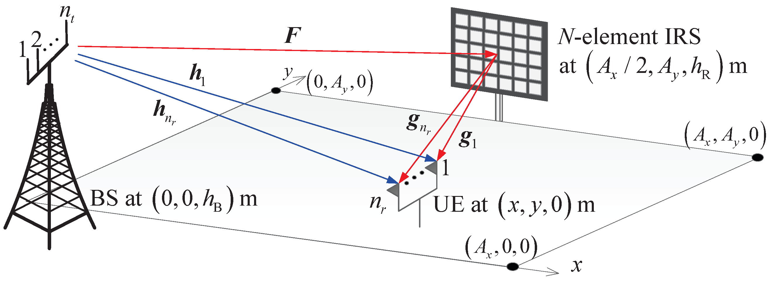
An IRS-aided multiple-antenna system, in which a BS (or access point) transfers information to the user equipment (UE) with the aid of IRS with N elements, is considered as shown in Figure 1. The UE receives signals with antennas from one BS through an IRS, i.e., downlink transmission is considered. The rectangular coverage area is defined by . The BS and IRS are located at and , respectively, where and are the heights of the BS and IRS, respectively. The location of UE is denoted by . The transmitted signals are reflected by N reflection elements on an IRS and received by antennas at the UE. The IRS is linked to the BS via wireless channels, and the phase shift of each IRS element is controlled by the BS. To prevent clutter, we denote the BS, IRS, and UE by B, R, and U, respectively, in equations throughout the paper.
2.1. Channel Model
The direct channel from the mth antenna of BS to the ith receive antenna of the UE is modeled as a Rayleigh fading channel as
where for and . Here, denotes a path loss between a and b as a function of the distance between them, in which . On the other hand, the IRS channels are modeled as a Rician channel, because the IRS is located at a distance of above the ground to ensure the line-of-sight (LoS), and usually the distance between the IRS and the UE is closer than that between the BS and the UE. The channel from the mth antenna of BS to the nth element of IRS is denoted by and its matrix representation is and ; the channel from the nth IRS element to the ith antenna at the UE is denoted by and its vector form is in which . All the channels related to the IRS elements are modeled as the Rician channels as follows [57,58]:
where and are the Rician factors of and , respectively; and denote the LoS components; while and denote the non-LoS (NLoS) components. The NLoS components are independent of one another and follow the standard complex Gaussian distribution with zero mean and unit variance, i.e., and .
The IRS is assumed to be an -by- rectangular uniform array in which and are the numbers of elements in each row and column of the array, respectively. The LoS channel between the mth antenna of BS and the IRS is modeled as follows [58]:
Here, and denote the center azimuth and elevation angle of arrival (AoA) at the IRS, and and are the phase steering vectors whose nth elements are defined as
respectively, with the separation d between neighboring elements in the vertical and horizontal directions and the carrier wavelength .
Similarly, the LoS channel between the IRS and the ith antenna of the UE is modeled as follows [58]:
where is the center azimuth AoA at the UE, and and denote the center azimuth and elevation angle of departure (AoD) from the IRS, respectively.
2.2. Signal Model
According to [44], an ideal IRS reflection coefficient can be modeled as a unit amplitude phase shifter, which can be expressed as , . Assuming that the analog phase shift values are available, i.e., , , the analog IRS phase shift vector is modeled as
Practically, however, the IRS with analog phase shifters is difficult to apply due to the high IRS network overhead of delivering the IRS phase shift information from the BS to the IRS and the hardware implementation cost. In this study, the IRS with a discrete phase shift method, whose phase shift values can be represented in finite number of bits, is considered. Let the number of available phase shift values be denoted by , then the b-bit resolution discrete IRS phase shift vector is modeled as
where is chosen in the finite candidate phase set which is defined by
Here, every adjacent pair of discrete phase shifts has an equally spaced phase interval of . As the resolution of the IRS discrete phase shift b increases, the phase interval reaches zero, which can be interpreted as the analog phase shifts.
The effective overall composite channel vector, denoted by at the ith antenna of the UE, is written as follows:
where .
After the CSI acquisition, which will be presented in the next section, the full CSI, such as , , and , can be obtained at the BS. The IRS phase shift vector is then calculated by the BS. Hence, the composite channel vector can be easily obtained from (9). Therefore, the spatial diversity schemes utilizing full CSI only at the transmitter, namely maximum ratio transmission (MRT) and space–time line code (STLC), can be applied to the IRS-aided multiple-antenna systems (To avoid additional CSI acquisition procedures, the spatial diversity schemes utilizing the full CSI at the UE, e.g., the maximum ratio combining [59] and space–time block code (STBC) [60], are not considered in this paper). Here, STLC is a dual scheme to the STBC that encodes the information symbols with full CSI at the transmitter and decodes them by simply combining the received signals with an extremely limited CSI at the receiver [61,62] (Owing to the beneficial and unique features of the STLC schemes, such as low computational complexity, full-diversity gain, and high scalability for the number of transmit antennas, the STLC technique has been vigorously applied to various multi-antenna communication systems. For example, multiuser/multicast/multi-stream multiplexing systems [62,63], cooperative communication systems [64], OFDM systems [65], mobile communication systems [66,67], secure wireless communication systems [68], and over-the-air computation systems [69]. Moreover, the statistical properties of SNR and signal-to-interference-plus-noise ratio and the performance of STLC, namely bit-error-rate and achievable rate, were analyzed in [70,71]). According to [61], the received SNR of the MRT and STLC can be generalized as follows:
where P and are the power of the transmit signal and additive white Gaussian noise, respectively; C is a code rate depending on the transmission scheme and antenna configurations [61]. The real-valued effective channel gain is written as follows:
From (10), it can be seen that the received SNR maximization of the IRS-aided multiple-antenna system is equivalent to maximizing the effective channel gain when the transmission scheme is chosen at the BS. Therefore, we concentrate on maximizing the effective channel gain in IRS phase shift design in the latter part of the paper.
3. Achievable Rate Model for IRS-Aided Multiple-Antenna Systems
To benefit from the IRS-aided multiple-antenna system, the CSI should be known at the BS to design the precoder and the IRS phase shift vector. Then, the IRS phase shift values designed from BS are transmitted to the IRS to control the phase value of each element. Here, the network overhead occurring from the channel estimation and IRS phase value transmission can deteriorate the communication performance. In this section, the achievable rate model is newly defined by introducing the CSI acquisition scenario and the two signaling overheads of the IRS system.
3.1. CSI Acquisition Scenario
As reported in [72,73,74], however, accurate and low-overhead channel estimation in IRS-based systems is one of the most critical challenges. Specifically, in (9) is required at the BS for the proposed IRS-aided system. Here, the effective channel can be obtained from the knowledge of (i) direct-link channels between BS and the ith antenna at UE; (ii) indirect-link channels and ; and (iii) the phase shift values (or ), . Since the phase shift values are designed from and , which will be shown in Section 4, we introduce an example framework to estimate and .
As the first step, the direct-link channel is estimated by sending an orthogonal sounding pilot from the ith antenna of UE to the BS while all IRS elements are turned off. In the second step, the BS estimates the indirect-link channels from the cascaded channels by using orthogonal pilots [29,75,76]. Specifically, since the cascaded channel is linked with the nth IRS element, all IRS elements except the nth IRS element are turned off, and the phase shift value of the nth IRS element is set to zero. For a given , repeating the cascaded channel estimation for all n, can be obtained. Therefore, a UE sends at least sounding pilot symbols in training duration because the BS estimates parameters, namely and for all and .
In static channels, the cascaded channel estimation approach is preferred to an individual channel estimation approach that separately estimates the channels and [77,78], because the number of parameters to be estimated is smaller in the cascaded channel than that in two individual channels. Under time-varying channels, however, the number of pilots (i.e., the length of training duration) can be reduced by employing the individual channel estimation approach. In this case, a UE is a mobile terminal whereas a BS and IRS are typically fixed, and the coherence time of a BS-IRS link for is much longer than that of an IRS-UE link for . Thus, the BS estimates less frequently than , and accordingly, the pilot overhead can be reduced. In this study, the channels are assumed to be static, and therefore, the cascaded channel estimation approach is employed. The whole training (i.e., estimation and signaling) procedure to obtain and is summarized as follows:
- Step 1:
- The user sends pilot symbols (training sequence) using the ith antenna while all IRS elements are turned off.
- Step 2:
- The BS estimates the direct channel .
- Step 3:
- The user sends pilot symbols (training sequence) using the ith antenna while the nth IRS element is turned on with and other IRS elements are turned off.
- Step 4:
- The BS estimates the indirect cascaded channel .
- Step 5:
- Repeat Steps 3 and 4 from to .
- Step 6:
- Repeat Steps 1–5 from to .
More sophisticated channel estimation algorithms can be developed. However, the main focus of this paper is not on channel estimation but on IRS phase shift design. In this study, therefore, a simple channel sounding and estimation algorithm is considered.
3.2. Network Overheads and Achievable Rate Models for Discrete Phase Shift IRS Systems
Assume that there is no dedicated control channel for sharing the phase shift values in the BS-IRS link. We then model the achievable rate considering the network signaling overhead for IRS phase shifts. Denoting the downlink communication duration and the operation bandwidth as T and W, respectively, the downlink achievable rate can be evaluated as follows:
where is the training duration for the pilot signaling; and is the controlling time of IRS, i.e., the time overhead for transferring the phase shift values from the BS to the IRS which depends on the IRS phase shift design schemes. Since the channel estimation for a communication link with IRS requires at least pilot transmissions from the user, as discussed in Section 3.1, with IRS is greater than without IRS which requires only pilot transmissions to estimate where . Considering the pilot transmission time, we model the training duration for channel estimation as below:
where is a sampling duration that can be modeled as reciprocal of the bandwidth, i.e., ; is the scaling factor depending on the pilot overhead (). To improve the CSI estimation accuracy, we can increase greater than one. On the other hand, as IRS phase shift value can be expressed as b bits, and the total controlling bits should be transferred for the IRS phase shifts. Assuming that (i) bits are modulated by a symbol, i.e., the modulation size of ; and (ii) there is no error for the IRS phase shift information transfer (i.e., the BS-IRS link is error-free for the IRS control signals), and can be defined as
By substituting (13) and (14) into (12), the practical downlink achievable rate of the IRS systems can be written as
Then, the overhead-aware achievable rate maximization problem can be formulated as
Here, denotes the maximum value of the discrete phase shift whose phase shift resolution is sufficiently high so that the phase interval . In this study, the -bit discrete phase shift is assumed to achieve identical performance to the analog phase shift in (6) with negligible power loss.
4. IRS Discrete Phase Shift Vector Design with Optimal Phase Shift Resolution
Unfortunately, the problem (16) is a high-dimensional combinatorial problem whose search complexity is given as . Specifically, when the discrete phase resolution b is given, the set of discrete phase value is determined so that the b-bit optimal phase shift vector can be obtained among a total of combinations. To find the optimal phase shift resolution, the concavity of (16a) over b is first numerically presented in this section. Then, utilizing the concavity of the achievable rate model, the incremental search method is proposed by fixing the resolution of the discrete phase shift from to the higher resolution.
When b is fixed to constant, the objective function (16a) is only a function of the IRS phase shift vector . As the logarithmic function is a monotonically increasing function, (16) is reduced to a problem of maximizing the real-valued effective channel gain with a b-bit discrete phase shift, which is formulated as follows:
Here, the effective channel gain can be expressed as a product of an IRS reflecting vector and an effective channel matrix as follows:
Here, is the complex-valued effective channel matrix of the IRS-aided system defined as
However, (17) is still a non-linear integer program, whose optimal solution can be obtained by applying the branch-and-bound algorithm [44]. Due to its NP-hardness, however, the worst-case complexity of the branch-and-bound method exponentially increases over N and b. Therefore, to reduce the computational complexity, the two general IRS discrete phase shift design approaches are introduced as follows.
One simplest approach to obtain the suboptimal solution of (17) is directly quantizing the optimal analog phase to the nearest discrete phase value among the finite discrete phase set . Once the analog phase shift vector is obtained from various existing methods, the b-bit uniform quantization is applied by mapping the nearest phase value among as follows:
From (20), the b-bit discrete phase shift vector is obtained. Here, various existing algorithms can be adopted to obtain the IRS analog phase shift, such as semidefinite relaxation [5], an alternating direction method of multiplier [79], manifold optimization [47], unit-modulus constraint relaxation (UCR) [80], and BCD [81]. In this study, the analog phase shift values obtained from the BCD algorithm are uniformly quantized by (20), the so-called quantized BCD algorithm in this study. The overall quantized BCD method is summarized in Algorithm 1. Here, is a maximum iteration number to guarantee the convergence of the BCD algorithm, which in this study, is set to . The more detailed information about the convergence of the BCD algorithm can be verified in [81].
Introducing another approach called greedy-based method, the phase shift values from the first to the Nth IRS elements are sequentially determined through N greedy steps. While the best phase shift values determined in the previous greedy steps are fixed, the best phase shift value in the current greedy step is selected from in (8) such that the objective function is maximized. The greedy-based algorithm is summarized in Algorithm 2.
| Algorithm 1 Quantized BCD-Based IRS Discrete Phase Shift Algorithm. |
|
| Algorithm 2 Greedy-Based IRS Discrete Phase Shift Algorithm. |
|
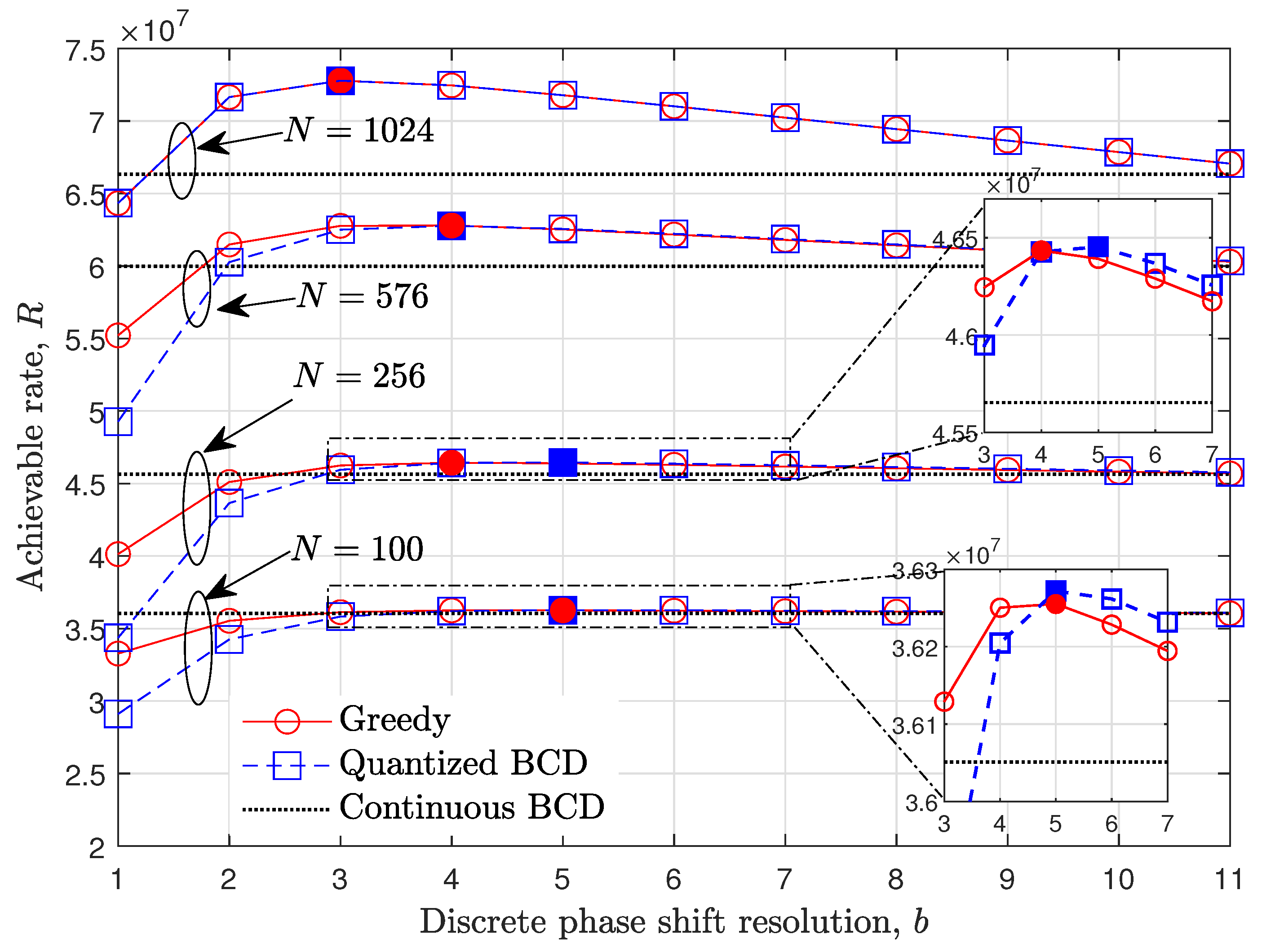
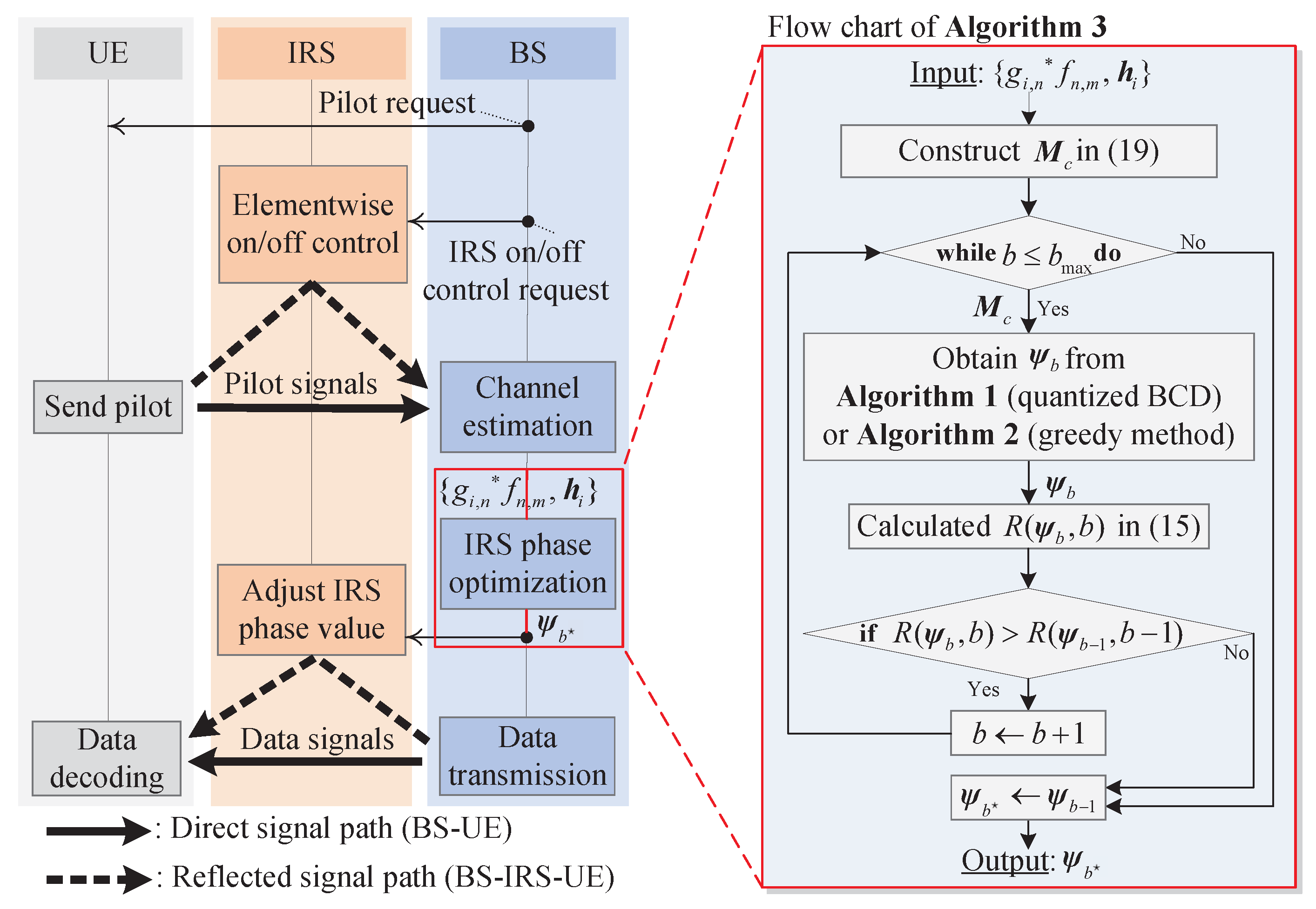
Since the achievable rate for the fixed discrete phase shift resolution can be calculated using obtained from Algorithms 1 or 2, the optimal b can be found from the various line search algorithms. From (15), it can be easily seen that the trade-off between the IRS passive beamforming gain and signaling overhead exists. Specifically, as b increases, the effective channel gain increases by precisely expressing the optimal phase shift value of each IRS element. As opposed to the , the data transmission time, i.e., in (15), linearly decreases as b increases due to the increase in IRS control signal overhead . In other words, the (15) is expected to be a concave function with respect to b. Figure 2 is provided to show the concavity of an achievable rate R over b for when the STLC transmission with , , and is considered (Here, the concavity of the discrete phase shift resolution b on achievable rate R can be analytically derived when IRS is deployed in the single-input single-output systems without the direct path between the BS and UE as [44,45]. However, when the direct path is considered, the derivations are not directly extended to multiple-antenna systems. Instead, the impact of discrete phase shift resolution is provided numerically for the various parameters). Here, the achievable rate of the analog phase shift method is calculated in fixed . The marker filled inside shows the optimal discrete phase shift resolution for each method. For example, when , the optimal resolution is 5, and monotonically decreases as N increases. From the results, it is expected that the can be obtained by searching in the incremental search direction. Specifically, by increasing the integer-valued b from one, the achievable rate is calculated unless the terminate condition is satisfied. When the condition is satisfied, the is chosen as the previous resolution value, i.e., , which is the optimal point if the concavity of (15) holds. The incremental search method to obtain an optimal IRS discrete phase shift resolution is summarized in Algorithm 3. The overall system procedures of the IRS systems and flow chart of the proposed incremental search-based method are given in Figure 3.
5. Performance Evaluation and Discussion
In this section, the optimal discrete phase shift resolution obtained by the proposed incremental search method is presented under various communication parameters. Furthermore, the achievable rate performance of the optimal discrete phase shift IRS is evaluated and compared to the analog phase shift method. During the simulations, the STLC encoding is applied as a transmit diversity scheme at the BS. The number of receiving antennas is set to two unless stated otherwise, so that the full rate transmission is available, i.e., [61]. Furthermore, is set to 12, and the analog phase shift values are assumed to be quantized in 12-bit resolution to be transferred to IRS. The simulations are conducted under the parameters used in [81], which are described in Table 1 (The azimuth and elevation angles in Table 1 can be obtained using the location of BS, IRS, and UE, which are and , respectively. The detailed procedures are omitted in this paper, [82] is left for interested readers). For the variety of performance comparisons, the quantized UCR-based discrete phase shift algorithm [80] is additionally provided during the simulations.
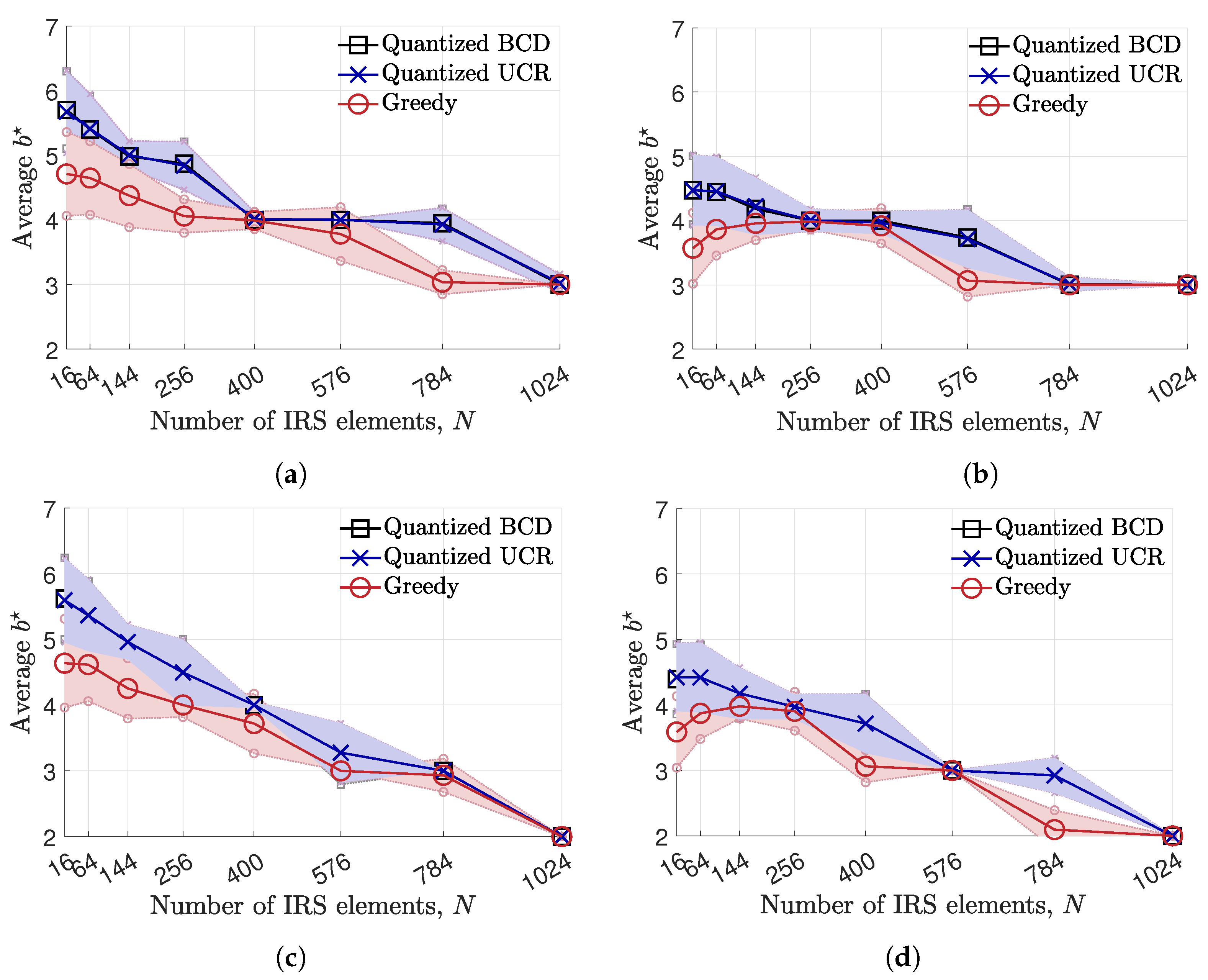
Following Algorithm 3, the average optimal discrete phase shift resolution for each number of IRS element N is demonstrated in Figure 4, when and . The error bar shows the average value of (solid line) and the interval of unit-standard deviation (the region between upper and lower dotted lines) for each phase shift method. From the results, the average obtained from the quantized BCD and UCR is generally higher than that obtained from the greedy algorithm. When N is large, e.g., , the values obtained from every suggested method converge to three when . However, when the pilot overhead is severe, i.e., , the is reduced to two, so as to alleviate the effect of pilot overhead. When , the average decreases as the number of IRS element N increases, as shown in Figure 2. This is because the smaller b is chosen to mitigate the IRS control signal overhead in (14). However, when , the average of the greedy algorithm adopts a lower when . On the other hand, it is observed that the quantized BCD and UCR algorithms obtain almost the same average value of , while the BCD shows a slightly lower variance in choosing compared to the UCR algorithm.
| Algorithm 3 Incremental Search-Based Discrete Phase Shift Resolution Finding Algorithm. |
|
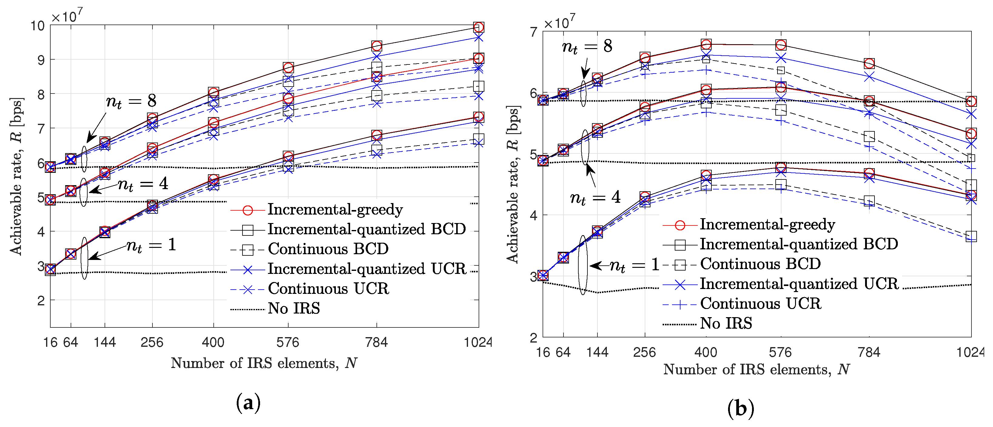
In Figure 5, the achievable rate R over the number of IRS element N is evaluated when , , and . The huge performance gap between no IRS and other methods verifies the advantages of deploying IRS. Furthermore, regardless of , it is verified that the performance of the greedy and quantized BCD-based discrete phase shift algorithm achieve the highest achievable rate compared to the quantized UCR algorithm and the existing analog phase shift method. Here, note that the discrete phase shifts always show better performance than the analog phase shift method due to the amount of network overhead (13) and (14). In other words, discrete phase shift methods can significantly reduce the amount of overhead with affordable degradation on the IRS passive beamforming gain compared to the analog phase shift method. For example, when and , about of the performance gap between the incremental-quantized BCD and the existing analog BCD methods. When the pilot overhead is relatively small, i.e., , the achievable rate from every method increases as N increases. Although the optimal discrete phase shift is considered, the achievable rate is degraded as N increases when . For example, when , the optimal number of IRS elements is 576 for the discrete phase shift methods, while it is 400 for the analog phase shift methods. On the other hand, the performance of the UCR method is severely degraded as N and increase due to its suboptimality which stems from fulfilling the relaxed constraint, as stated in [80].
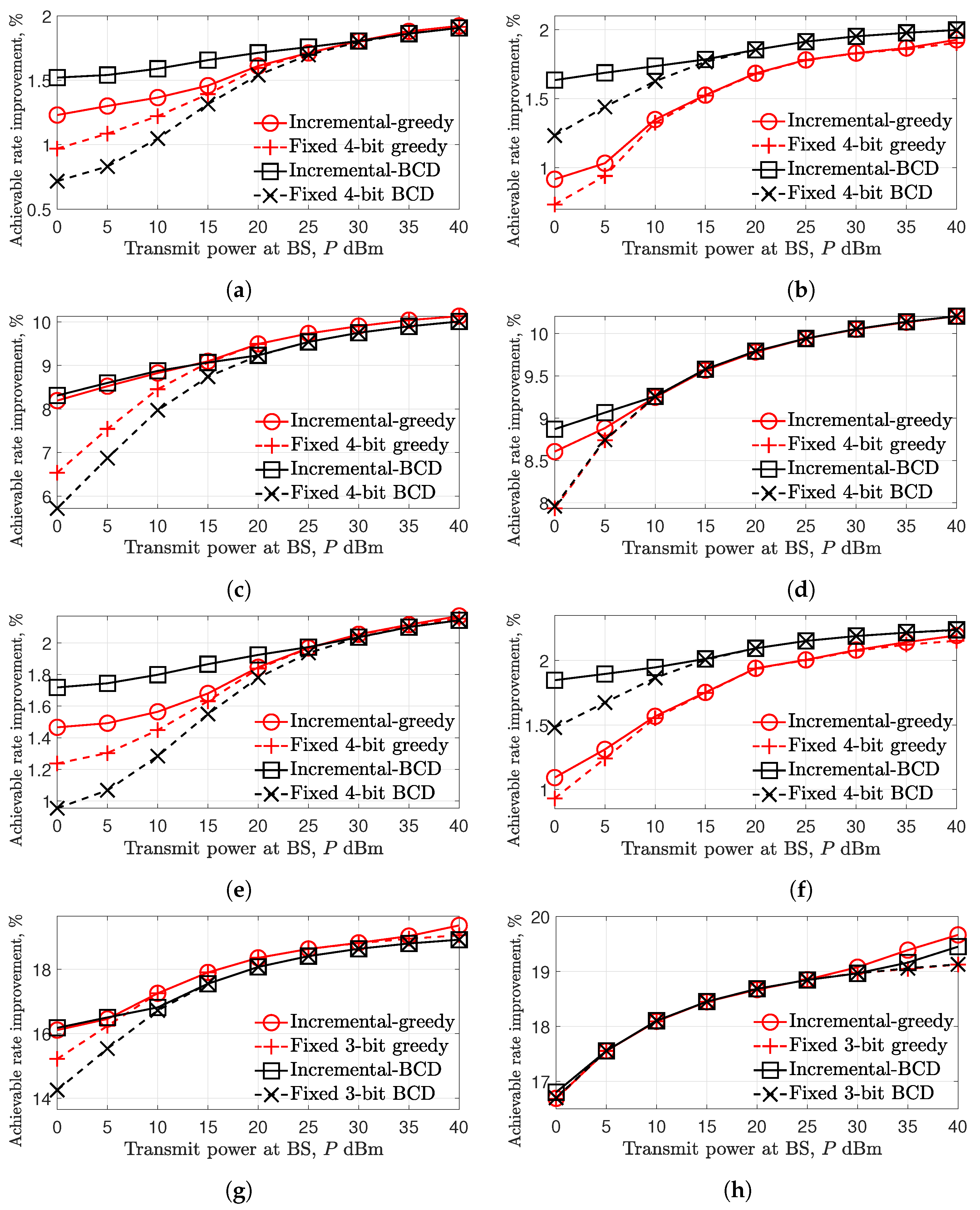
In Figure 6, the achievable rate improvement with a baseline of BCD-based analog phase shift method is evaluated over P when , , , and . Here, the performance of the UCR algorithm is omitted due to its degraded performance compared to the BCD algorithm verified in Figure 5. Instead, the discrete phase shift with fixed 3 and 4-bit methods are compared with the proposed incremental-based method. From the results, it is verified that the discrete phase shift methods are expected to obtain large achievable rate improvement as N and increases. For example, in Figure 6h, more than of the achievable rate is improved compared to the analog phase shift method. Interestingly, the superiority between two-sub algorithms, i.e., greedy and BCD algorithms, can be pointed out as follows:
Remark 1.
When N is relatively small, e.g., , the BCD algorithm outperforms the greedy algorithm, especially in a low-SNR regime (from Figure 6a,b,e,f).
This is especially the case in Figure 6b, when , and the quantized BCD algorithm outperforms the greedy algorithm in the entire SNR range.
Remark 2.
When N is relatively large and is small, e.g., and , the greedy algorithm shows better performance compared to the quantized BCD algorithms in high SNR regime (from Figure 6c,g).
For the case when and , which corresponded to Figure 6d,h, two sub-algorithms present comparable performance in the SNR range between 10 and while showing their superiority in the low- and high-SNR regimes in Figure 6d,h, respectively. From the remarks, the sub-algorithms can be effectively chosen according to the received signal power level and the numbers of IRS elements, N, and transmit antennas, .
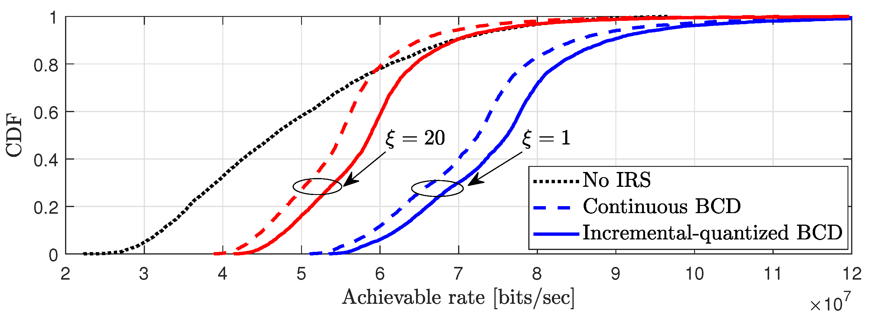
To demonstrate the performance improvement of the IRS discrete phase shift method for the entire coverage area, the 4000 UEs are randomly generated to uniformly cover the two-dimensional coverage area in Figure 7. Specifically, the UEs are generated in the area in the x axis range of and y axis range of to effectively show the performance of IRS. It is seen that the achievable rate is small when , compared to when . Specifically, at , approximately improvements are accomplished in quantized BCD compared to the analog BCD method for both and . Interestingly, when the pilot overhead is severe, i.e., , it is shown that the performance of the IRS with analog BCD does not always outperform the systems without the IRS. This is because the effect of the IRS network overhead is larger than the IRS beamforming gain when the analog phase shift method is used. However, by properly choosing the discrete phase resolution, the quantized BCD method can provide considerable performance enhancement in the multiple antenna systems.
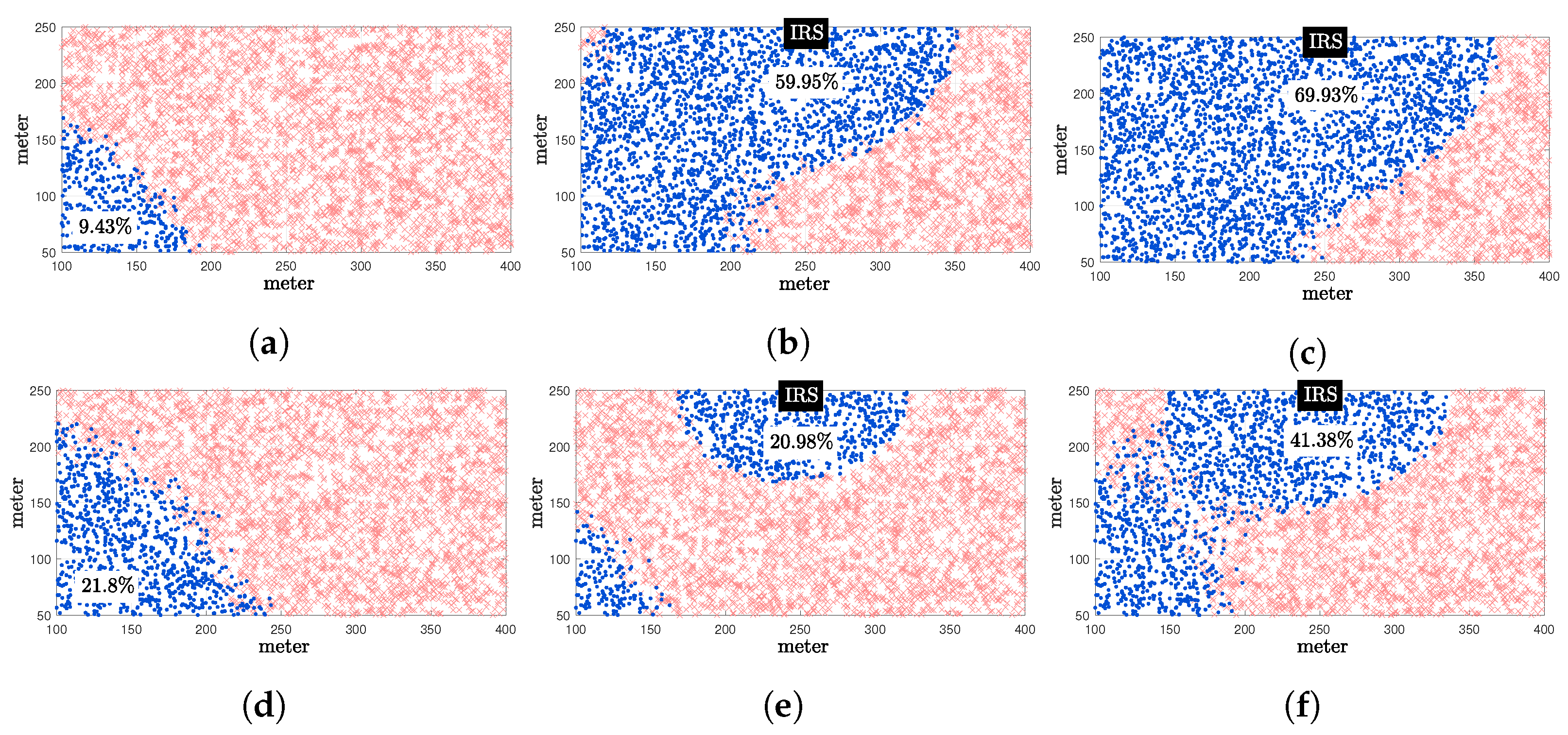
In Figure 8, the spatial distributions of UEs that satisfy the target rate are illustrated. The target rates are set to 7 and for (Figure 8a–c) and (Figure 8d–f), respectively. Note that, by observing uniformly distributed 4000 UEs within the considered area, the increased number of UEs who satisfy the target rate can be interpreted as the growth of the coverage area. When , only of the UEs were satisfied the target rate of , while and of the UEs were satisfied, for IRS with BCD and quantized BCD methods, respectively. Compared to the IRS with the BCD method, about of coverage is extended by adopting the quantized BCD method. Similarly, in Figure 8e, of coverage is obtained by utilizing the analog BCD method, which is even lower than the system without IRS. However, with the quantized BCD method in Figure 8f, approximately larger coverage is obtained compared to the system without IRS, which can also be verified in Figure 7.
6. Conclusions
In this study, the IRS discrete phase shift method is investigated to reduce the network overhead of IRS-aided multiple-antenna systems. Finding the optimal resolution of the discrete phase shift that maximizes the overhead-aware achievable rate is a combinatorial problem demanding substantial computational complexity. Considering the concavity of the achievable rate model, the proposed incremental search-based method with two low-complexity sub-algorithms can efficiently find the optimal resolution. Furthermore, it is numerically shown that the superiorities between two sub-algorithms exist under the various communication parameters. Consequently, the proposed method can improve by more than of the achievable rate compared to the existing analog phase shift method when the 1024-element IRS is adopted. Moreover, about of the coverage can be extended by using the proposed method with 576-element IRS.
Author Contributions
Conceptualization, J.K. and J.J.; methodology, J.K.; software, J.K.; validation, J.J., H.Y. and X.K.; formal analysis, J.K.; Writing—Original draft preparation, J.K. and J.J.; Writing—Review and editing, H.Y. and X.K.; visualization, J.K.; supervision, J.J.; project administration, J.J.; funding acquisition, J.J. All authors have read and agreed to the published version of the manuscript.
Funding
This research was supported in part by the National Research Foundation of Korea(NRF) grant funded by the Korea government (MSIT) (2022R1A2C1003750), Institute of Information & communications Technology Planning & Evaluation (IITP) grant funded by the Korea government(MSIT) (No.2021-0-00874, Development of Next Generation Wireless Access Technology Based on Space Time Line Code, 50%), and in part by the Chung-Ang University Graduate Research Scholarship in 2021.
Conflicts of Interest
The authors declare no conflict of interest.
Abbreviations
The following abbreviations are used in this manuscript:
| AoA | Angle of arrival |
| AoD | Angle of departure |
| BCD | Block coordinate descent |
| BS | Base station |
| CSI | Channel state information |
| IRS | Intelligent reflecting surface |
| LoS | Line of sight |
| MISO | Multiple-input multiple-output |
| MRT | Maximum ratio transmission |
| NLoS | Non-line-of-sight |
| NOMA | Non-orthogonal multiple access |
| PIN | Positive–intrinsic–negative |
| SNR | Signal-to-noise ratio |
| STBC | Space–time block code |
| STLC | Space–time line code |
| UCR | Unit-modulus constraint |
| UE | User equipment |
References
- Gong, S.; Lu, X.; Hoang, D.T.; Niyato, D.; Shu, L.; Kim, D.I.; Liang, Y.C. Toward smart wireless communications via intelligent reflecting surfaces: A contemporary survey. IEEE Commun. Surv. Tut. 2020, 22, 2283–2314. [Google Scholar] [CrossRef]
- Pan, C.; Ren, H.; Wang, K.; Kolb, J.F.; Elkashlan, M.; Chen, M.; Di Renzo, M.; Hao, Y.; Wang, J.; Swindlehurst, A.L.; et al. Reconfigurable intelligent surfaces for 6G systems: Principles, applications, and research directions. IEEE Commun. Mag. 2021, 59, 14–20. [Google Scholar] [CrossRef]
- Liu, Y.; Liu, X.; Mu, X.; Hou, T.; Xu, J.; Di Renzo, M.; Al-Dhahir, N. Reconfigurable intelligent surfaces: Principles and opportunities. IEEE Commun. Surv. Tuts. 2021, 23, 1546–1577. [Google Scholar] [CrossRef]
- Wu, Q.; Zhang, S.; Zheng, B.; You, C.; Zhang, R. Intelligent reflecting surface-aided wireless communications: A tutorial. IEEE Trans. Commun. 2021, 69, 3313–3351. [Google Scholar] [CrossRef]
- Wu, Q.; Zhang, R. Intelligent reflecting surface enhanced wireless network via joint active and passive beamforming. IEEE Trans. Wirel. Commun. 2019, 18, 5394–5409. [Google Scholar] [CrossRef] [Green Version]
- Chen, J.; Liang, Y.C.; Pei, Y.; Guo, H. Intelligent reflecting surface: A programmable wireless environment for physical layer security. IEEE Access 2019, 7, 82599–82612. [Google Scholar] [CrossRef]
- Wijewardena, M.; Samarasinghe, T.; Hemachandra, K.T.; Atapattu, S.; Evans, J.S. Physical layer security for intelligent reflecting surface assisted two-way communications. IEEE Commun. Lett. 2021, 25, 2156–2160. [Google Scholar] [CrossRef]
- Guan, X.; Wu, Q.; Zhang, R. Intelligent reflecting surface assisted secrecy communication: Is artificial noise helpful or not? IEEE Wirel. Commun. Lett. 2020, 9, 778–782. [Google Scholar] [CrossRef] [Green Version]
- Xie, H.; Xu, J.; Liu, Y.F. Max-min fairness in IRS-aided multi-cell MISO systems with joint transmit and reflective beamforming. IEEE Trans. Wirel. Commun. 2021, 20, 1379–1393. [Google Scholar] [CrossRef]
- Han, H.; Zhao, J.; Zhai, W.; Xiong, Z.; Niyato, D.; Di Renzo, M.; Pham, Q.V.; Lu, W.; Lam, K.Y. Reconfigurable intelligent surface aided power control for physical-layer broadcasting. IEEE Trans. Commun. 2021, 69, 7821–7836. [Google Scholar] [CrossRef]
- Yang, G.; Xu, X.; Liang, Y.C.; Renzo, M.D. Reconfigurable intelligent surface-assisted non-orthogonal multiple access. IEEE Trans. Wirel. Commun. 2021, 20, 3137–3151. [Google Scholar] [CrossRef]
- Zheng, B.; Wu, Q.; Zhang, R. Intelligent reflecting surface-assisted multiple access With user pairing: NOMA or OMA? IEEE Commun. Lett. 2020, 24, 753–757. [Google Scholar] [CrossRef] [Green Version]
- Ding, Z.; Vincent Poor, H. A simple design of IRS-NOMA transmission. IEEE Commun. Lett. 2020, 24, 1119–1123. [Google Scholar] [CrossRef] [Green Version]
- Zhou, G.; Pan, C.; Ren, H.; Wang, K.; Nallanathan, A. Intelligent reflecting surface aided multigroup multicast MISO communication systems. IEEE Trans. Signal Process. 2020, 68, 3236–3251. [Google Scholar] [CrossRef] [Green Version]
- Gopi, S.; Kalyani, S.; Hanzo, L. Intelligent reflecting surface assisted beam index-modulation for millimeter wave communication. IEEE Trans. Wirel. Commun. 2021, 20, 983–996. [Google Scholar] [CrossRef]
- Wang, P.; Fang, J.; Yuan, X.; Chen, Z.; Li, H. Intelligent reflecting surface-assisted millimeter wave communications: Joint active and passive precoding design. IEEE Trans. Veh. Technol. 2020, 69, 14960–14973. [Google Scholar] [CrossRef]
- Huang, C.; Zappone, A.; Alexandropoulos, G.C.; Debbah, M.; Yuen, C. Reconfigurable intelligent surfaces for energy efficiency in wireless communication. IEEE Trans. Wirel. Commun. 2019, 18, 4157–4170. [Google Scholar] [CrossRef] [Green Version]
- Basar, E.; Di Renzo, M.; De Rosny, J.; Debbah, M.; Alouini, M.S.; Zhang, R. Wireless communications through reconfigurable intelligent surfaces. IEEE Access 2019, 7, 116753–116773. [Google Scholar] [CrossRef]
- Jeong, H.; Park, E.; Phon, R.; Lim, S. Mechatronic reconfigurable intelligent-surface-driven indoor fifth-generation wireless communication. Adv. Intell. Syst. 2002. early access articles. [Google Scholar] [CrossRef]
- Han, Y.; Tang, W.; Jin, S.; Wen, C.K.; Ma, X. Large intelligent surface-assisted wireless communication exploiting statistical CSI. IEEE Trans. Veh. Technol. 2019, 68, 8238–8242. [Google Scholar] [CrossRef]
- Liang, Y.C.; Long, R.; Zhang, Q.; Chen, J.; Cheng, H.V.; Guo, H. Large intelligent surface/antennas (LISA): Making reflective radios smart. J. Commun. Net. 2019, 4, 40–50. [Google Scholar] [CrossRef]
- Bariah, L.; Muhaidat, S.; Sofotasios, P.C.; Bouanani, F.E.; Dobre, O.A.; Hamouda, W. Large intelligent surface-assisted nonorthogonal multiple access for 6G networks: Performance analysis. IEEE Internet Things J. 2021, 8, 5129–5140. [Google Scholar] [CrossRef]
- Kundu, N.K.; Mckay, M.R. Large intelligent surfaces with channel estimation overhead: Achievable rate and optimal configuration. IEEE Wirel. Commun. Lett. 2021, 10, 986–990. [Google Scholar] [CrossRef]
- He, Z.Q.; Yuan, X. Cascaded channel estimation for large intelligent metasurface assisted massive MIMO. IEEE Wirel. Commun. Lett. 2020, 9, 210–214. [Google Scholar] [CrossRef] [Green Version]
- Tan, X.; Sun, Z.; Jornet, J.M.; Pados, D. Increasing indoor spectrum sharing capacity using smart reflect-array. In Proceedings of the IEEE International Conference on Communications (ICC), Kuala Lumpur, Malaysia, 22–27 May 2016; pp. 1–6. [Google Scholar] [CrossRef] [Green Version]
- Tan, X.; Sun, Z.; Koutsonikolas, D.; Jornet, J.M. Enabling indoor mobile millimeter-wave networks based on smart reflect-arrays. In Proceedings of the IEEE INFOCOM 2018—IEEE Conference on Computer Communications, Honolulu, HI, USA, 16–19 April 2018; pp. 270–278. [Google Scholar] [CrossRef]
- Liaskos, C.; Tsioliaridou, A.; Pitsillides, A.; Akyildiz, I.F.; Kantartzis, N.V.; Lalas, A.X.; Dimitropoulos, X.; Ioannidis, S.; Kafesaki, M.; Soukoulis, C. Design and development of software defined metamaterials for nanonetworks. IEEE Circuits Syst. Mag. 2015, 15, 12–25. [Google Scholar] [CrossRef]
- Liaskos, C.; Tsioliaridou, A.; Nie, S.; Pitsillides, A.; Ioannidis, S.; Akyildiz, I. An interpretable neural network for configuring programmable wireless environments. In Proceedings of the IEEE 20th Internet Workshop on Signal Processing Advances in Wireless Communications (SPAWC), Cannes, France, 2–5 July 2019; pp. 1–5. [Google Scholar] [CrossRef] [Green Version]
- Mishra, D.; Johansson, H. Channel estimation and low-complexity beamforming design for passive intelligent surface assisted MISO wireless energy transfer. In Proceedings of the ICASSP 2019–2019 IEEE International Conference on Acoustics, Speech and Signal Processing (ICASSP), Brighton, UK, 12–17 May 2019; pp. 4659–4663. [Google Scholar] [CrossRef]
- Mishra, D.; Larsson, E.G. Passive intelligent surface assisted MIMO powered sustainable IoT. In Proceedings of the 2020 IEEE International Conference on Acoustics, Speech and Signal Processing (ICASSP), Barcelona, Spain, 4–8 May 2020; pp. 8961–8965. [Google Scholar] [CrossRef]
- Huang, C.; Zappone, A.; Debbah, M.; Yuen, C. Achievable rate maximization by passive intelligent mirrors. In Proceedings of the 2018 IEEE International Conference on Acoustics, Speech and Signal Processing (ICASSP), Calgary, AB, Canada, 15–20 April 2018; pp. 3714–3718. [Google Scholar] [CrossRef] [Green Version]
- Cui, T.J.; Qi, M.Q.; Wan, X.; Zhao, J.; Cheng, Q. Coding metamaterials, digital metamaterials and programmable metamaterials digital metamaterials and programmable metamaterials. Light Sci. Appl. 2014, 3, 1–9. [Google Scholar] [CrossRef] [Green Version]
- Zhang, L.; Chen, X.Q.; Liu, S.; Zhang, Q.; Zhao, J.; Dai, J.Y.; Bai, G.D.; Wan, X.; Cheng, Q.; Castaldi, G.; et al. Coding metamaterials, digital metamaterials and programmable metamaterials. Nat. Commun. 2018, 8, 1–7. [Google Scholar] [CrossRef] [Green Version]
- Guo, H.; Liang, Y.C.; Chen, J.; Larsson, E.G. Weighted sum-rate maximization for reconfigurable intelligent surface aided wireless networks. IEEE Trans. Wirel. Commun. 2020, 19, 3064–3076. [Google Scholar] [CrossRef] [Green Version]
- Huang, W.; Ding, W.; Kai, C.; Yi, Y.; Huang, Y. Joint placement and beamforming design for IRS-enhanced multiuser MISO systems. IEEE Trans. Commun. 2022, 70, 6678–6692. [Google Scholar] [CrossRef]
- Ma, H.; Zhang, H.; Zhu, Y.; Qian, Y. Wireless powered intelligent reflecting surface for improving broadcasting channels. IEEE Trans. Wirel. Commun. 2022. early access articles. [Google Scholar] [CrossRef]
- Perović, N.S.; Renzo, M.D.; Flanagan, M.F. Channel capacity optimization using reconfigurable intelligent surfaces in indoor mmWave environments. In Proceedings of the ICC 2020 –2020 IEEE International Conference on Communications (ICC), Dublin, Ireland, 7–11 June 2020; pp. 1–7. [Google Scholar]
- Zhang, Q.; Liang, Y.C.; Poor, H.V. Reconfigurable intelligent surface assisted MIMO symbiotic radio networks. arXiv 2020, arXiv:2002.00340. [Google Scholar] [CrossRef]
- Yuan, J.; Liang, Y.C.; Joung, J.; Feng, G.; Larsson, E.G. Intelligent reflecting surface-assisted cognitive radio system. IEEE Trans. Commun. 2021, 69, 675–687. [Google Scholar] [CrossRef]
- Björnson, E.; Özdogan, Ö.; Larsson, E.G. Reconfigurable intelligent surfaces: Three myths and two critical questions. IEEE Commun. Mag. 2020, 58, 90–96. [Google Scholar] [CrossRef]
- Zappone, A.; Di Renzo, M.; Shams, F.; Qian, X.; Debbah, M. Overhead-aware design of reconfigurable intelligent surfaces in smart radio environments. IEEE Trans. Wirel. Commun. 2021, 20, 126–141. [Google Scholar] [CrossRef]
- Yang, H.; Yang, F.; Xu, S.; Mao, Y.; Li, M.; Cao, X.; Gao, J. A 1-Bit 10×10 Reconfigurable reflectarray antenna: Design, optimization, and experiment. IEEE Trans. Antennas Propag. 2016, 64, 2246–2254. [Google Scholar] [CrossRef]
- Jia, S.; Yuan, X.; Liang, Y.C. Reconfigurable intelligent surfaces for energy efficiency in D2D communication network. IEEE Wirel. Commun. Lett. 2021, 10, 683–687. [Google Scholar] [CrossRef]
- Wu, Q.; Zhang, R. Beamforming optimization for wireless network aided by intelligent reflecting surface with discrete phase shifts. IEEE Trans. Commun. 2020, 68, 1838–1851. [Google Scholar] [CrossRef] [Green Version]
- Zhang, H.; Di, B.; Song, L.; Han, Z. Reconfigurable intelligent surfaces assisted communications with limited phase shifts: How many phase shifts are enough? IEEE Trans. Veh. Technol. 2020, 69, 4498–4502. [Google Scholar] [CrossRef] [Green Version]
- You, C.; Zheng, B.; Zhang, R. Channel estimation and passive beamforming for intelligent reflecting surface: Discrete phase shift and progressive refinement. IEEE J. Sel. Areas Commun. 2020, 38, 2604–2620. [Google Scholar] [CrossRef]
- Chen, J.C. Beamforming optimization for intelligent reflecting surface-aided MISO communication systems. IEEE Trans. Veh. Technol. 2021, 70, 504–513. [Google Scholar] [CrossRef]
- An, J.; Gan, L. The low-complexity design and optimal training overhead for IRS-assisted MISO systems. IEEE Wirel. Commun. Lett. 2021, 10, 1820–1824. [Google Scholar] [CrossRef]
- Peng, Z.; Li, T.; Pan, C.; Ren, H.; Wang, J. RIS-aided D2D communications relying on statistical CSI with imperfect hardware. IEEE Commun. Lett. 2022, 26, 473–477. [Google Scholar] [CrossRef]
- Xie, X.; He, C.; Luan, H.; Dong, Y.; Yang, K.; Gao, F.; Wang, Z.J. A joint optimization framework for IRS-assisted energy self-sustainable IoT networks. IEEE Internet Things J. 2022, 9, 13767–13779. [Google Scholar] [CrossRef]
- Niu, H.; Lin, Z.; Chu, Z.; Zhu, Z.; Xiao, P.; Nguyen, H.X.; Lee, I.; Al-Dhahir, N. Joint beamforming design for secure RIS-assisted IoT networks. IEEE Internet Things J. 2022. early access articles. [Google Scholar] [CrossRef]
- Chen, J.; Xie, Y.; Mu, X.; Jia, J.; Liu, Y.; Wang, X. Energy efficient resource allocation for IRS assisted CoMP systems. IEEE Trans. Wirel. Commun. 2022, 21, 5688–5702. [Google Scholar] [CrossRef]
- Yan, W.; Sun, G.; Hao, W.; Zhu, Z.; Chu, Z.; Xiao, P. Machine learning-based beamforming design for millimeter wave IRS communications with discrete phase shifters. IEEE Wirel. Commun. Lett. 2022. early access articles. [Google Scholar] [CrossRef]
- Chen, J.; Guo, L.; Jia, J.; Shang, J.; Wang, X. Resource allocation for IRS assisted SGF NOMA transmission: A MADRL approach. IEEE J. Sel. Areas Commun. 2022, 40, 1302–1316. [Google Scholar] [CrossRef]
- Sun, Z.; Jing, Y. On the performance of multi-antenna IRS-assisted NOMA networks with continuous and discrete IRS phase shifting. IEEE Trans. Wirel. Commun. 2022, 21, 3012–3023. [Google Scholar] [CrossRef]
- Li, H.; Cai, W.; Liu, Y.; Li, M.; Liu, Q.; Wu, Q. Intelligent reflecting surface enhanced wideband MIMO-OFDM communications: From practical model to reflection optimization. IEEE Trans. Commun. 2021, 69, 4807–4820. [Google Scholar] [CrossRef]
- Wu, Q.; Zhang, R. Towards smart and reconfigurable environment: Intelligent reflecting surface aided wireless network. IEEE Commun. Mag. 2020, 58, 106–112. [Google Scholar] [CrossRef] [Green Version]
- Wang, J.; Liang, Y.C.; Joung, J.; Yuan, X.; Wang, X. Joint beamforming and reconfigurable intelligent surface design for two-way relay networks. IEEE Trans. Commun. 2021, 69, 5620–5633. [Google Scholar] [CrossRef]
- Li, S.; Smith, P.J.; Dmochowski, P.A.; Yin, J. Analysis of analog and digital MRC in massive MU-MIMO systems over correlated channels. J. Commun. Netw. 2021, 6, 454–462. [Google Scholar] [CrossRef]
- Kermani, V.M.; Kermani, H.M.; Morsali, A. Coding advantage optimization of space-time-frequency block codes. J. Commun. Netw. 2020, 2, 85–92. [Google Scholar] [CrossRef]
- Joung, J. Space–time line code. IEEE Access 2018, 6, 1023–1041. [Google Scholar] [CrossRef]
- Joung, J. Space–time line code for massive MIMO and multiuser systems with antenna allocation. IEEE Access 2018, 6, 962–979. [Google Scholar] [CrossRef]
- Joung, J.; Fan, J. Linear precoding for space–time line code-based multicast systems. IEEE Trans. Veh. Technol. 2022, 71, 12386–12391. [Google Scholar] [CrossRef]
- Joung, J.; Choi, J. Space–time line codes with power allocation for regenerative two-way relay systems. IEEE Trans. Veh. Technol. 2019, 68, 4884–4893. [Google Scholar] [CrossRef]
- Wu, C.; Xiao, Y.; Guan, Y.L.; Wang, J.; Li, X.; Yang, P. Space–time/frequency line coded OFDM: System design and practical implementation. IEEE Access 2019, 7, 151915–151928. [Google Scholar] [CrossRef]
- Yu, H.; Joung, J. Frame structure design for vehicular-to-roadside unit communications using space–time line code under time-varying channels. IEEE Syst. J. 2021, 15, 3150–3153. [Google Scholar] [CrossRef]
- Joung, J.; Yu, H.; Zhao, J. Bandwidth design for energy-efficient unmanned aerial vehicle using space–time line code. IEEE Syst. J. 2021, 15, 3154–3157. [Google Scholar] [CrossRef]
- Joung, J.; Choi, J.; Jung, B.C.; Yu, S. Artificial noise injection and its power loading methods for secure space–time line coded systems. Entropy 2019, 21, 1–12. [Google Scholar] [CrossRef] [Green Version]
- Joung, J.; Fan, J. Over-the-air computation strategy using space–time line code for data collection by multiple unmanned aerial vehicles. IEEE Access 2021, 9, 105230–105241. [Google Scholar] [CrossRef]
- Pang, Y.; Xiao, X.; Lei, X.; Li, Y. Performance analysis and antenna selection for space time line code. IEEE Access 2020, 8, 193503–193511. [Google Scholar] [CrossRef]
- Lim, S.C.; Joung, J. Transmit antenna selection for space–time line code systems. IEEE Trans. Commun. 2021, 69, 786–798. [Google Scholar] [CrossRef]
- Wei, L.; Huang, C.; Alexandropoulos, G.C.; Yuen, C.; Zhang, Z.; Debbah, M. Channel estimation for RIS-empowered multi-user MISO wireless communications. IEEE Trans. Commun. 2021, 69, 4144–4157. [Google Scholar] [CrossRef]
- Zheng, B.; You, C.; Mei, W.; Zhang, R. A survey on channel estimation and practical passive beamforming design for intelligent reflecting surface aided wireless communications. IEEE Commun. Surv. Tut. 2022, 24, 1035–1071. [Google Scholar] [CrossRef]
- Noh, S.; Lee, J.; Lee, G.; Seo, K.; Sung, Y.; Yu, H. Channel estimation techniques for RIS-assisted communication: Millimeter-wave and sub-THz systems. IEEE Veh. Technol. Mag. 2022, 17, 64–73. [Google Scholar] [CrossRef]
- Wang, Z.; Liu, L.; Cui, S. Channel estimation for intelligent reflecting surface assisted multiuser communications: Framework, algorithms, and analysis. IEEE Trans. Wirel. Commun. 2020, 19, 6607–6620. [Google Scholar] [CrossRef]
- Jensen, T.L.; De Carvalho, E. An optimal channel estimation scheme for intelligent reflecting surfaces based on a minimum variance unbiased estimator. In Proceedings of the 2020 IEEE International Conference on Acoustics, Speech and Signal Processing (ICASSP), Barcelona, Spain, 4–8 May 2020; pp. 5000–5004. [Google Scholar] [CrossRef] [Green Version]
- Zhang, J.; Qi, C.; Li, P.; Lu, P. Channel estimation for reconfigurable intelligent surface aided massive MIMO system. In Proceedings of the IEEE Signal Processing Advances in Wireless Communications (SPAWC), Atlanta, GA, USA, 26–29 May 2020; pp. 1–5. [Google Scholar] [CrossRef]
- Hu, C.; Dai, L.; Han, S.; Wang, X. Two-timescale channel estimation for reconfigurable intelligent surface aided wireless communications. IEEE Trans. Commun. 2021, 69, 7736–7747. [Google Scholar] [CrossRef]
- Boyd, S.; Parikh, N.; Chu, E.; Peleato, B.; Eckstein, J. Distributed optimization and statistical learning via the alternating direction method of multipliers. Found. Trends Mach. Learn. 2011, 3, 1–122. [Google Scholar] [CrossRef]
- Kim, J.; Joung, J.; Lim, K. Intelligent reflecting surface-aided space–time line coded systems. IEEE Wirel. Commun. Lett. 2022, 11, 245–249. [Google Scholar] [CrossRef]
- Kim, J.; Choi, J.; Joung, J.; Liang, Y.C. Modified block coordinate descent method for intelligent reflecting surface-aided space–time line coded systems. IEEE Wirel. Commun. Lett. 2022, 11, 1820–1824. [Google Scholar] [CrossRef]
- Hu, X.; Zhong, C.; Zhang, Y.; Chen, X.; Zhang, Z. Location information aided multiple intelligent reflecting surface systems. IEEE Trans. Commun. 2020, 68, 7948–7962. [Google Scholar] [CrossRef]
- Further Advancements for E-UTRA Physical Layer Aspects (Release 9), Technical Report TS 36.814; 3GPP, 2010.
Figure 1.
IRS-aided -by- system model in -by- area. A BS has antennas, an IRS has N elements (-by-), and a UE has antennas. The BS, IRS, and UE are denoted by B, R, and U, respectively.
Figure 1.
IRS-aided -by- system model in -by- area. A BS has antennas, an IRS has N elements (-by-), and a UE has antennas. The BS, IRS, and UE are denoted by B, R, and U, respectively.

Figure 2.
Achievable rate evaluation over the discrete phase shift resolution, b, for when UE is at , and STLC transmission with , is adopted.
Figure 2.
Achievable rate evaluation over the discrete phase shift resolution, b, for when UE is at , and STLC transmission with , is adopted.

Figure 3.
Overall system procedures and the flow chart of the IRS-aided systems.

Figure 4.
Average across the number of IRS elements, N, when UE is at , and . (a) and . (b) and . (c) and . (d) and .
Figure 4.
Average across the number of IRS elements, N, when UE is at , and . (a) and . (b) and . (c) and . (d) and .

Figure 5.
Achievable rate evaluation over the number of IRS elements, N, when UE is at , , , . (a) . (b) .
Figure 5.
Achievable rate evaluation over the number of IRS elements, N, when UE is at , , , . (a) . (b) .

Figure 6.
Achievable rate improvement over the transmit power at BS, P, when UE is at . (a) With 256-element IRS, , and . (b) With 256-element IRS, , and . (c) With 1024-element IRS, , and . (d) With 1024-element IRS, , and . (e) With 256-element IRS, , and . (f) With 256-element IRS, , and . (g) With 1024-element IRS, , and . (h) With 1024-element IRS, , and .

Figure 7.
CDF of achievable rate performance for randomly generated 4000 UEs in area. , and .

Figure 8.
Spatial distributions of randomly generated 4000 UEs when , , and . Dot marks ‘·’ for UEs satisfying the target rate; Cross marks ‘×’ for UEs achieving achievable rate less than the target rate. (a) Without IRS, target rate of and . (b) -element IRS with BCD method, target rate of and . (c) -element IRS with quantized BCD method, target rate of and . (d) Without IRS, target rate of and . (e) -element IRS with BCD method, target rate of and . (f) -element IRS with quantized BCD method, target rate of and .


Table 1.
Simulation Environment Parameters [81].
Table 1.
Simulation Environment Parameters [81].
| Parameters | Values |
|---|---|
| Coverage area | |
| BS/IRS locations | |
| UE location | , where and |
| Azimuth angles for BS and UE | , |
| Azimuth angles for IRS | , |
| Elevation angles for IRS | , |
| Number of IRS elements | |
| Bandwidth/carrier frequency [83] | / |
| Antenna (IRS element) spacing [82] | Half wavelength, i.e., |
| Downlink duration/pilot overhead parameter | / |
| Rician factor [58] | |
| Noise Figure [58] | |
| Antenna gain for BS/UE [58] | / |
| Pathloss for Rician [83] | |
| Pathloss for Rayleigh [83] | |
| Computer/simulator | -GHz CPU and 32-GB RAM / MATLAB-2021a |
Publisher’s Note: MDPI stays neutral with regard to jurisdictional claims in published maps and institutional affiliations. |
© 2022 by the authors. Licensee MDPI, Basel, Switzerland. This article is an open access article distributed under the terms and conditions of the Creative Commons Attribution (CC BY) license (https://creativecommons.org/licenses/by/4.0/).
Share and Cite
MDPI and ACS Style
Kim, J.; Yu, H.; Kang , X.; Joung , J. Discrete Phase Shifts of Intelligent Reflecting Surface Systems Considering Network Overhead. Entropy 2022, 24, 1753. https://doi.org/10.3390/e24121753
AMA Style
Kim J, Yu H, Kang X, Joung J. Discrete Phase Shifts of Intelligent Reflecting Surface Systems Considering Network Overhead. Entropy. 2022; 24(12):1753. https://doi.org/10.3390/e24121753
Chicago/Turabian StyleKim, Jaehong, Heejung Yu, Xin Kang , and Jingon Joung . 2022. "Discrete Phase Shifts of Intelligent Reflecting Surface Systems Considering Network Overhead" Entropy 24, no. 12: 1753. https://doi.org/10.3390/e24121753
Note that from the first issue of 2016, this journal uses article numbers instead of page numbers. See further details here.