Thermodynamic and Economic Analyses of Reformative Design for High Back-Pressure Heating in Coal-Fueled Cogeneration Units

 ,
,
Abstract
:1. Introduction
2. System Description
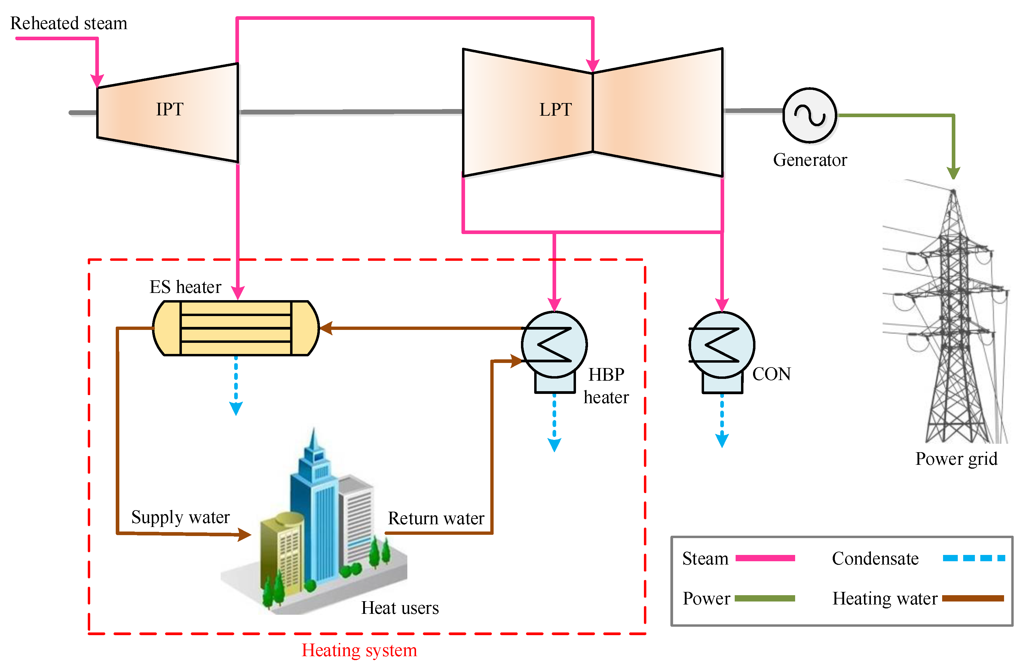
2.1. Regular HBP Heating System
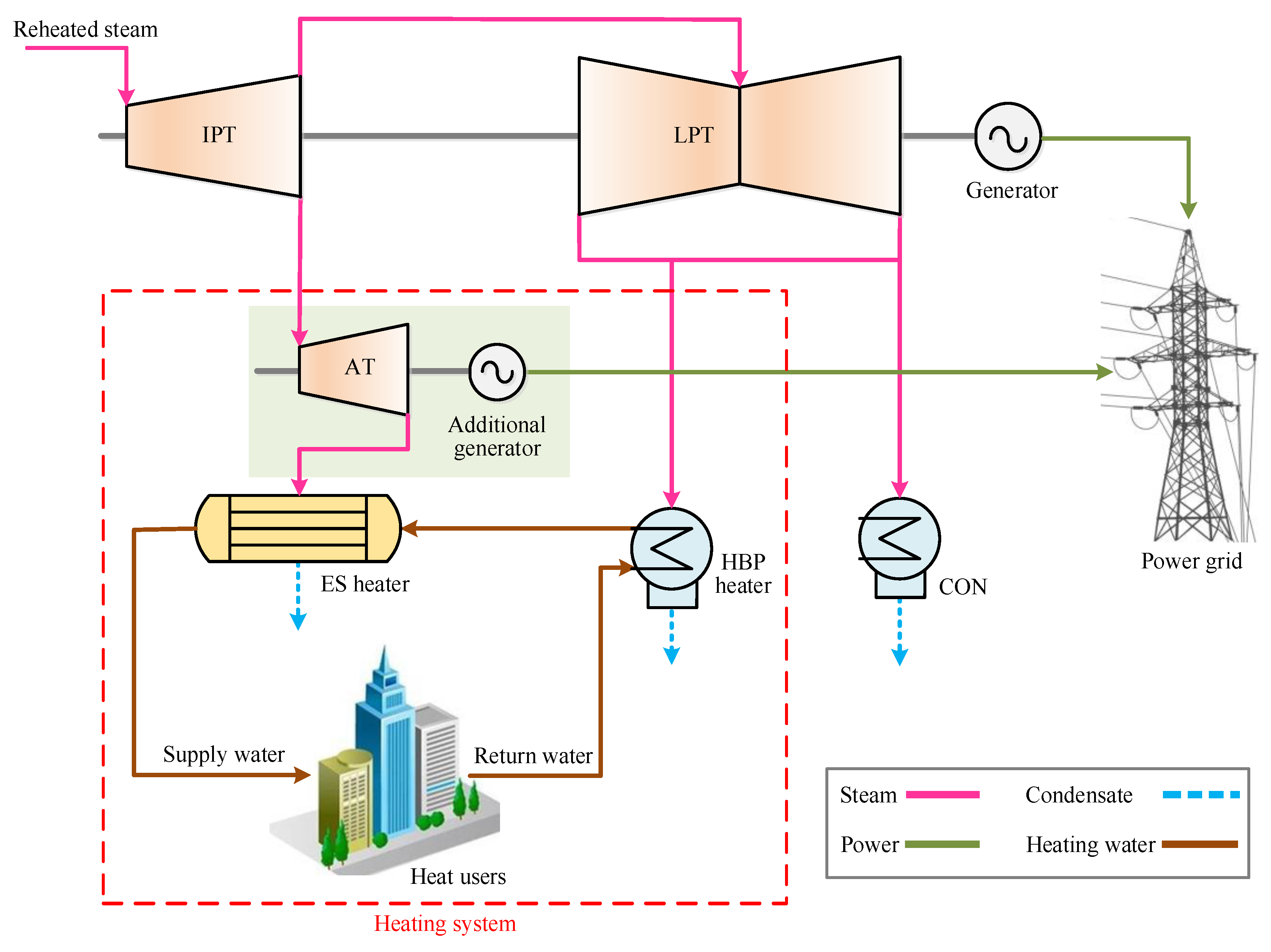
2.2. Proposed HBP Heating System
3. System Simulation and Evaluation Criteria
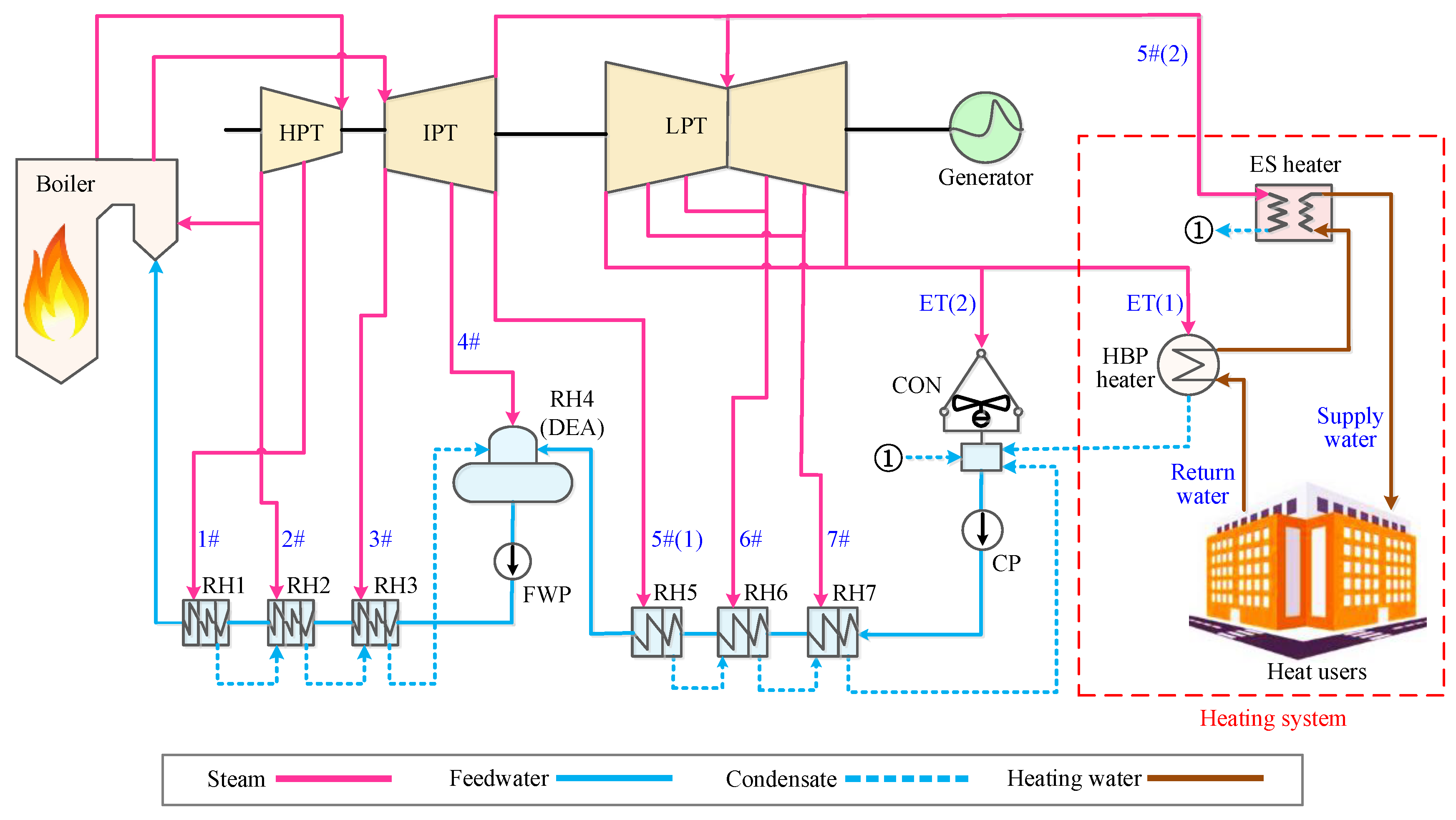
3.1. Reference HBP–CHP Unit
3.2. Model Development and Verification
3.3. Thermal Evaluation Criteria
3.3.1. Energy Efficiency
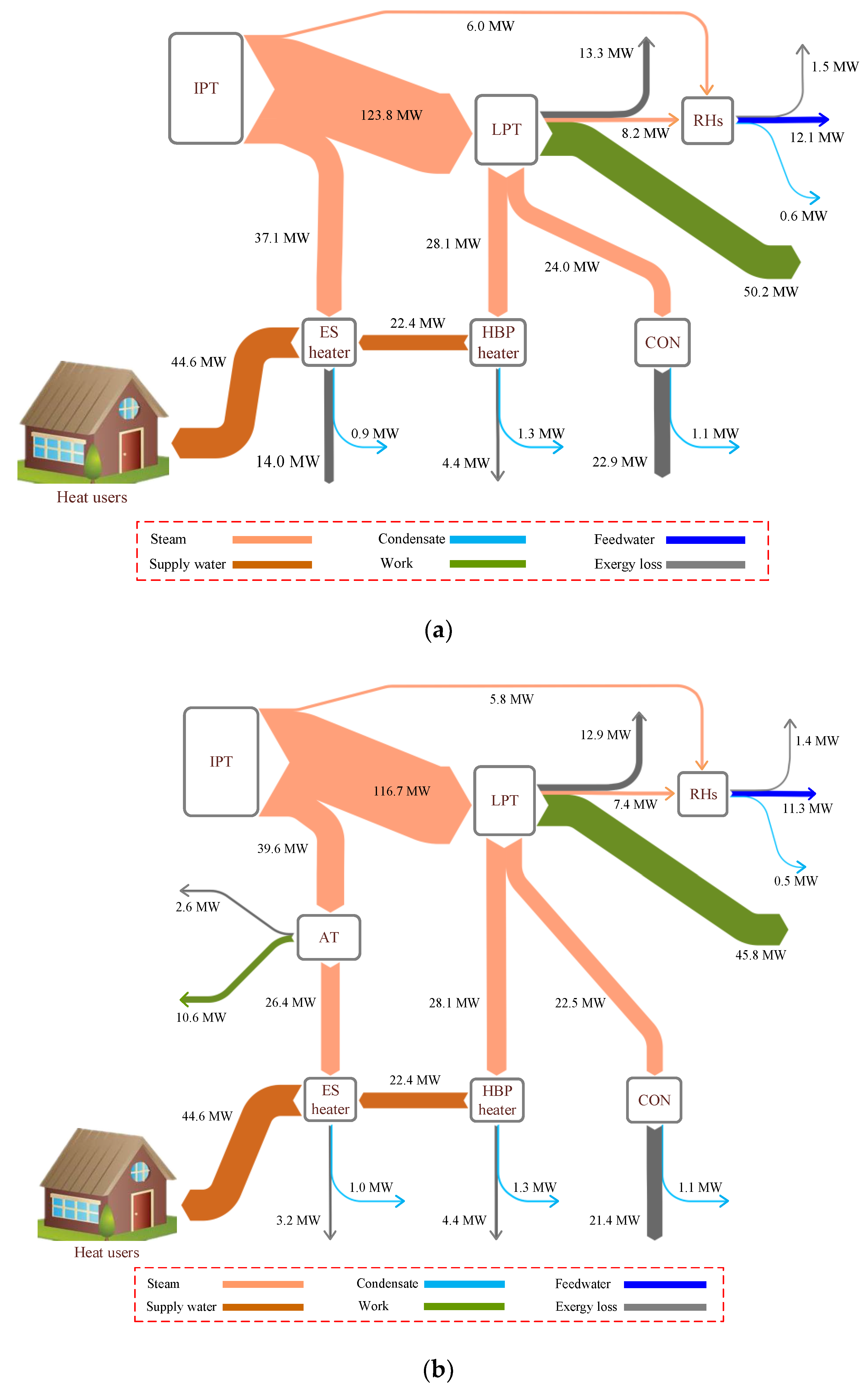
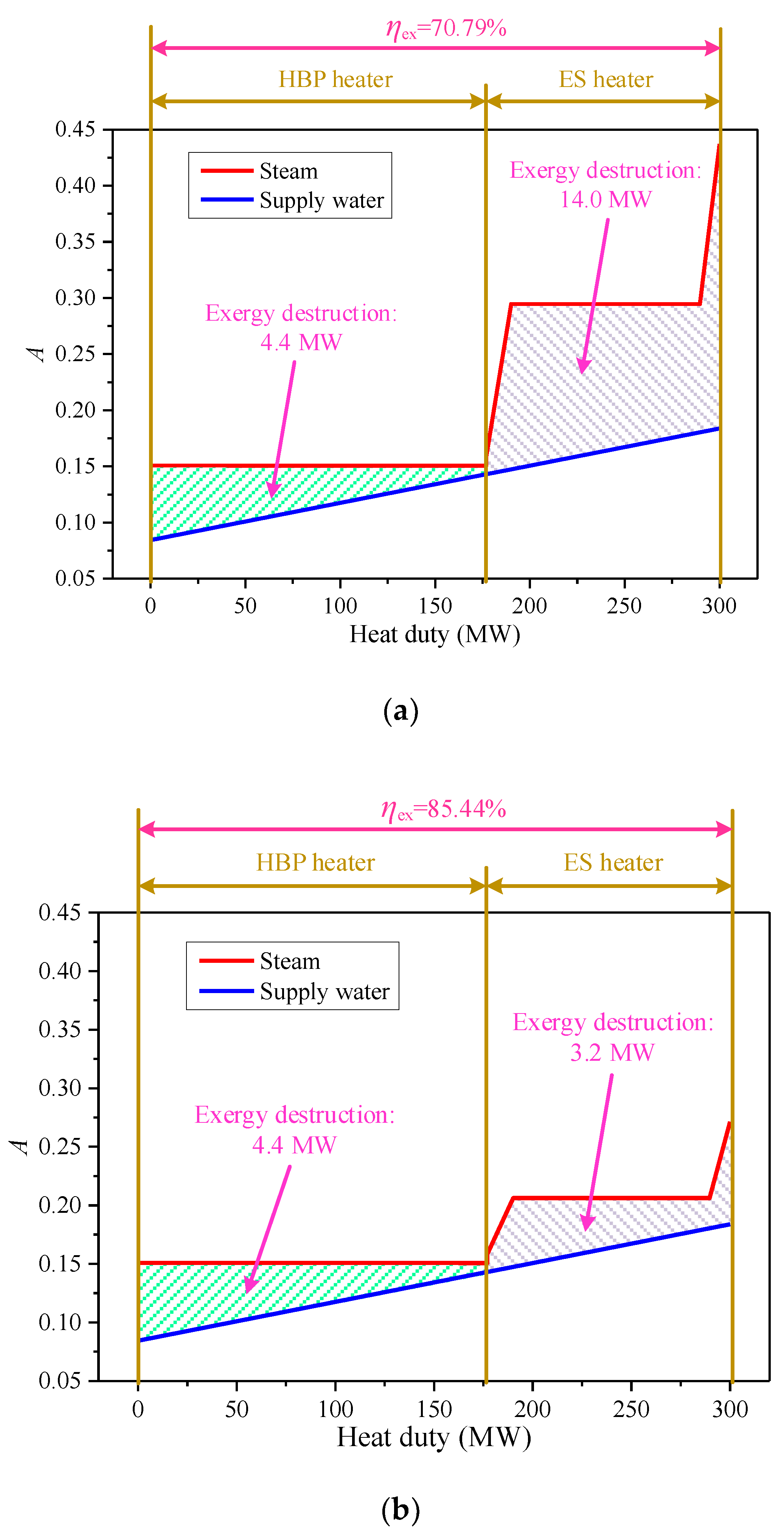
3.3.2. Exergy Efficiency
4. Results and Discussion
4.1. Overall Performance
- the coal consumption rate of the cogeneration unit is maintained constant;
- the pressures and temperatures of the main steam and reheated steam are kept identical;
- the boiler efficiency is fixed
- the heat output of the cogeneration unit and the supply water and return water temperatures remain unchanged;
- the influence of surrounding on the cogeneration unit is ignored.
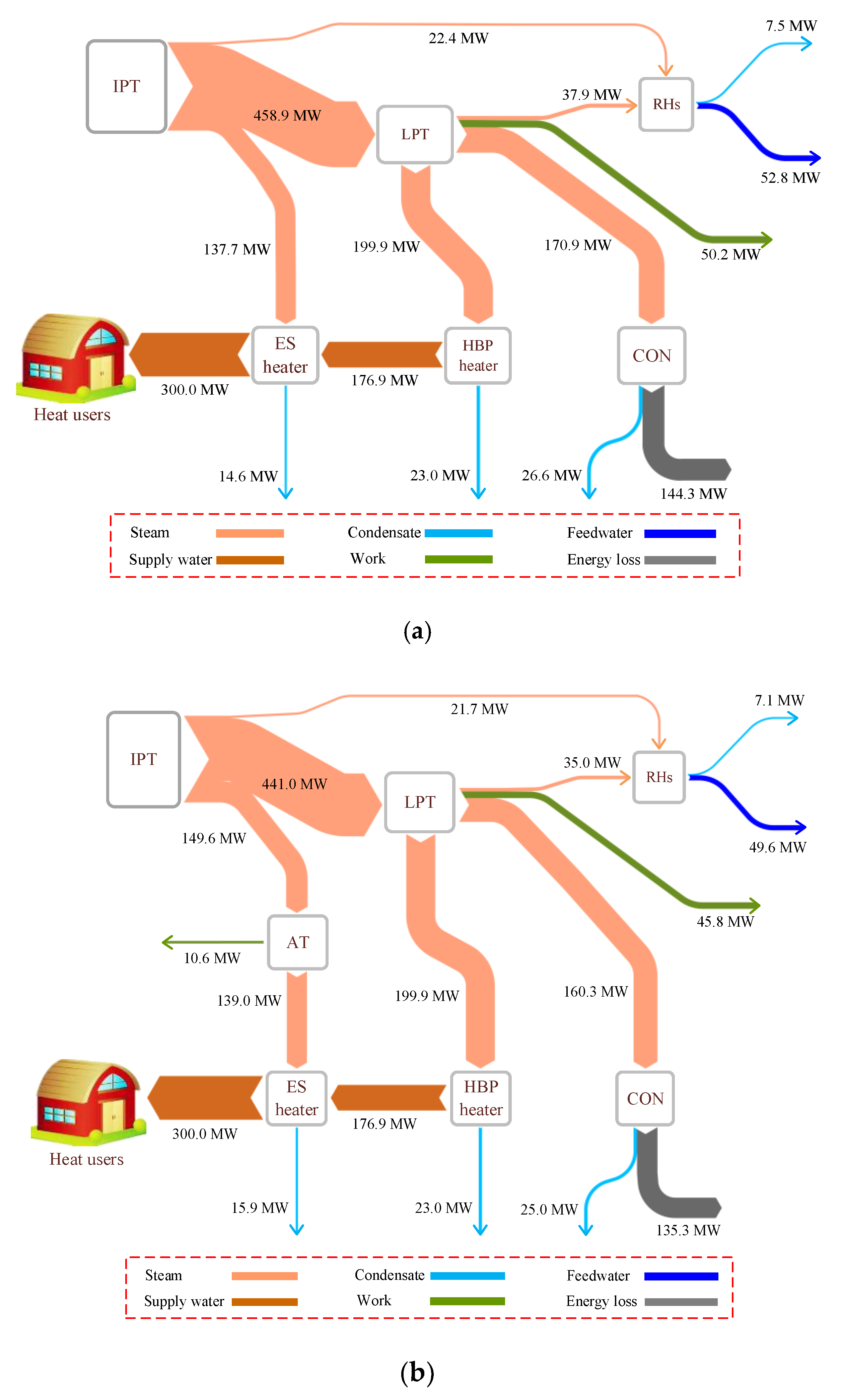
4.2. Energy and Exergy Analyses
4.3. Parametric Analysis
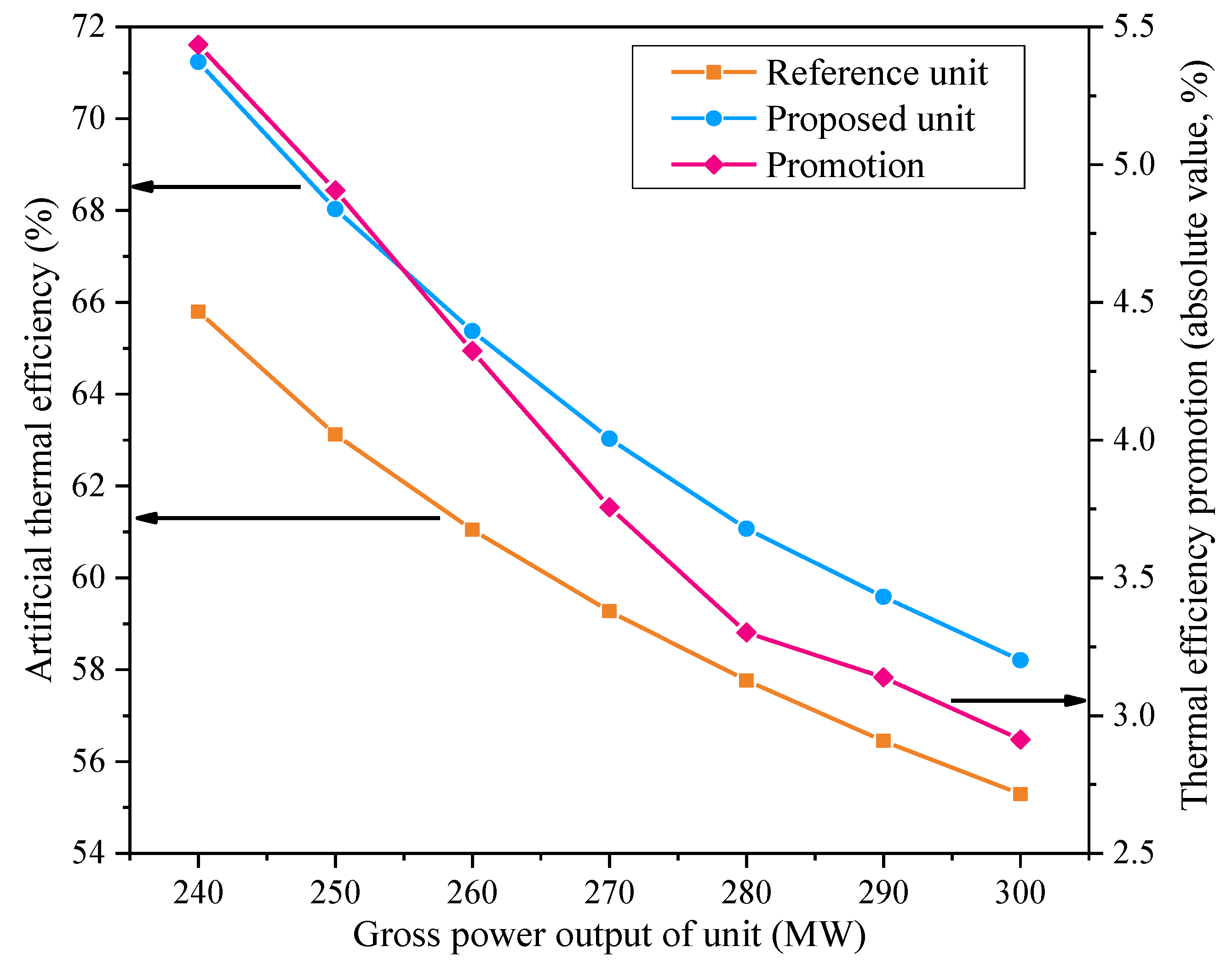
4.3.1. Effect of Unit Power Output
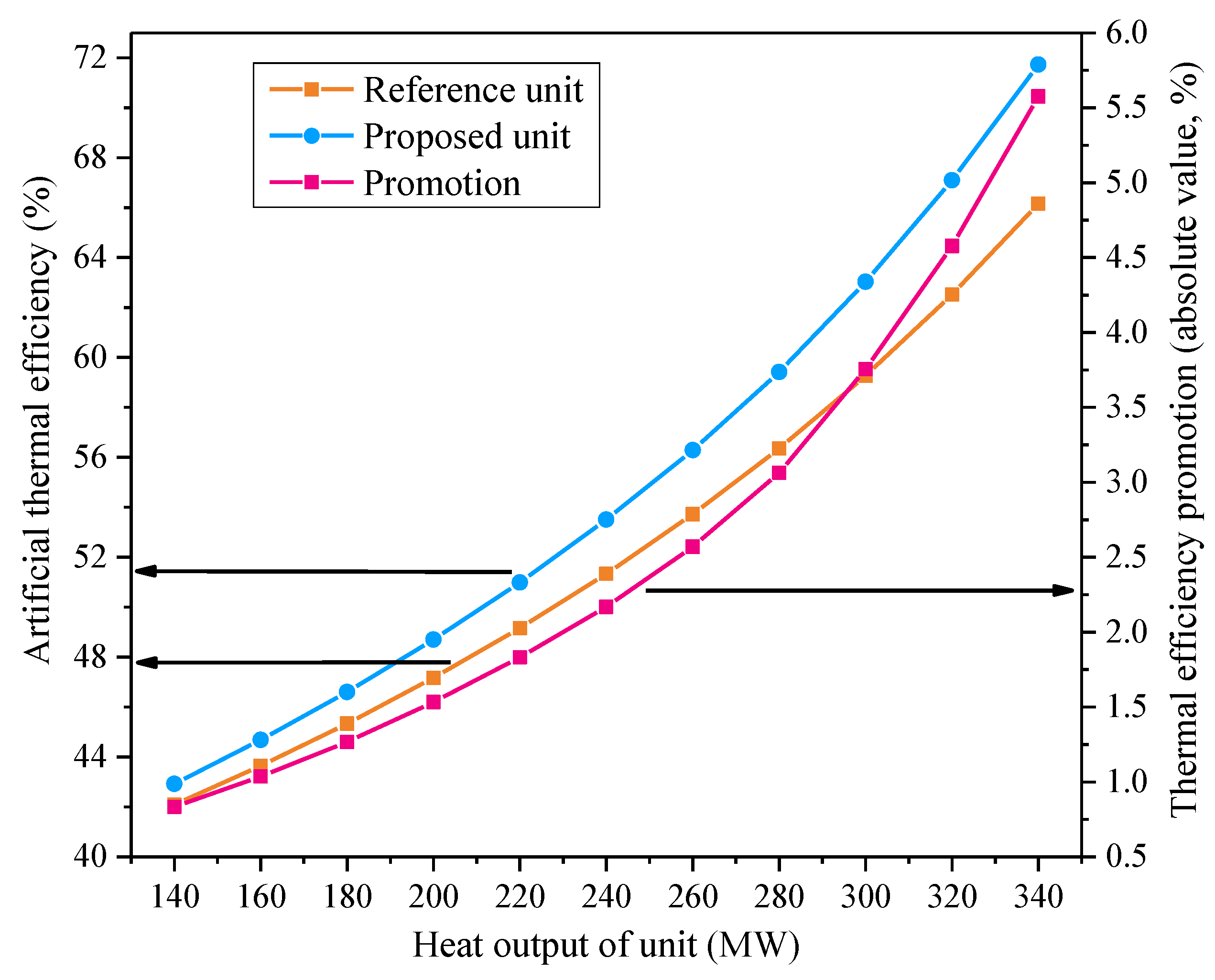
4.3.2. Effect of Unit Heat Output
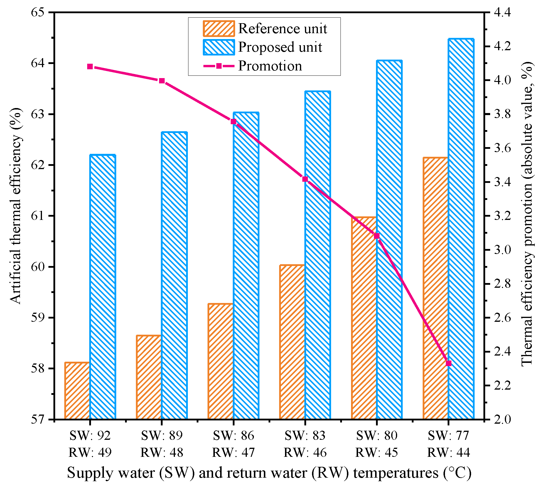
4.3.3. Effect of Supply Water and Return Water Temperatures
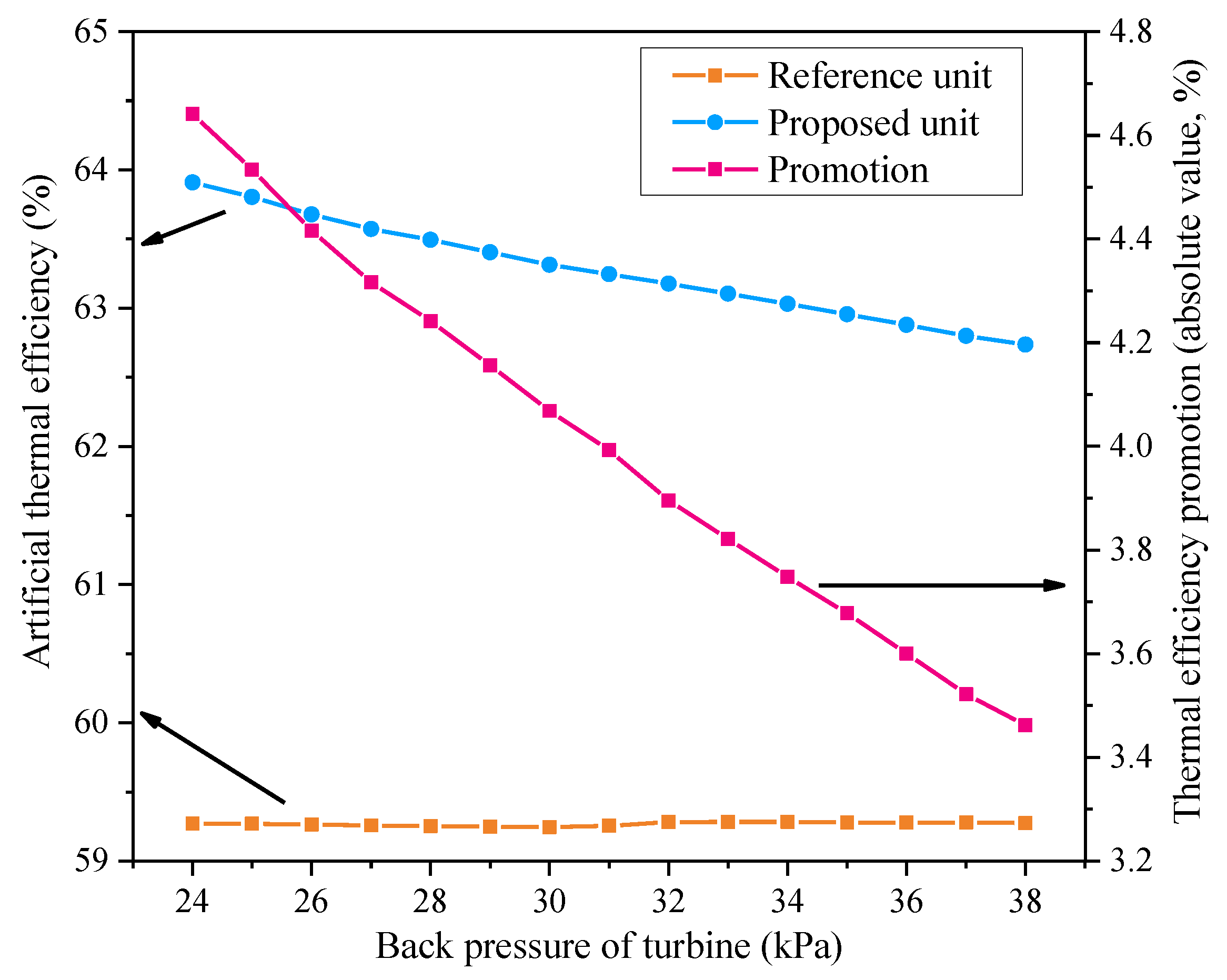
4.3.4. Effect of Turbine Back Pressure
5. Techno-Economic Analysis
6. Conclusions
Author Contributions
Funding
Acknowledgments
Conflicts of Interest
Nomenclature
| Abbreviations | |||
| AHE | absorption heat exchange | FWP | feed water pump |
| AHP | absorption heat pump | HBP | high back pressure |
| AT | additional turbine | HPT | high-pressure turbine |
| CHP | combined heat and power | IPT | intermediate-pressure turbine |
| CON | condenser | LPT | low-pressure turbine |
| CP | condensate pump | RH | regenerative heater |
| DEA | deaerator | RW | return water |
| EUD | energy utilization diagram | SW | supply water |
| ES | extraction steam | THA | turbine heat acceptance |
| ET | exhaust steam | ||
| Symbols | |||
| Δ | difference | P | power, MW |
| η | efficiency | Q | heat, MW or kJ |
| A | energy level | S | entropy, kJ/K |
| ATE | artificial thermal efficiency | T | temperature, K |
| C | cash flow, million USD | c | electricity price, USD/MWh |
| DDP | dynamic payback period, year | ex | specific exergy, kJ/kg |
| EUF | energy utilization factor | h | specific enthalpy, kJ/kg |
| EX | exergy, MW | i | discount rate |
| N | plant operation hours | m | mass flow rate, kg/s |
| NPV | net present value, million USD | s | specific entropy, kJ/kgK |
| Subscripts | |||
| 0 | environmental state | g | generator |
| CI | capital investment | h | heating |
| NAE | net annual earning | hot | hot fluid |
| O&M | operation and maintenance | in | inlet |
| b | boiler | net | net value |
| cold | cold fluid | m | matter |
| e | electricity | nom | nominal |
| es | extraction steam | out | outlet |
| et | exhaust steam | rec | recovery |
| ex | exergy | ref | reference |
| f | fuel | ||
References
- Mago, P.J.; Smith, A.D. Methodology to estimate the economic, emissions, and energy benefits from combined heat and power systems based on system component efficiencies. Int. J. Energy Res. 2014, 38, 1457–1466. [Google Scholar] [CrossRef]
- Ganjehkaviri, A.; Jaafar, M. Energy analysis and multi-objective optimization of an internal combustion engine-based CHP system for heat recovery. Entropy 2014, 16, 5633–5653. [Google Scholar] [CrossRef]
- Mohammadi-Ivatloo, B.; Moradi-Dalvand, M.; Rabiee, A. Combined heat and power economic dispatch problem solution using particle swarm optimization with time varying acceleration coefficients. Electr. Power Syst. Res. 2013, 95, 9–18. [Google Scholar] [CrossRef]
- Vögelin, P.; Koch, B.; Georges, G.; Boulouchos, K. Heuristic approach for the economic optimisation of combined heat and power (CHP) plants: Operating strategy, heat storage and power. Energy 2017, 121, 66–77. [Google Scholar] [CrossRef]
- Lund, H.; Šiupšinskas, G.; Martinaitis, V. Implementation strategy for small CHP-plants in a competitive market: The case of Lithuania. Appl. Energy 2005, 82, 214–227. [Google Scholar] [CrossRef]
- Streckienė, G.; Martinaitis, V.; Andersen, A.N.; Katz, J. Feasibility of CHP-plants with thermal stores in the German spot market. Appl. Energy 2009, 86, 2308–2316. [Google Scholar] [CrossRef]
- Beigvand, S.D.; Abdi, H.; La Scala, M. Combined heat and power economic dispatch problem using gravitational search algorithm. Electr. Power Syst. Res. 2016, 133, 160–172. [Google Scholar] [CrossRef]
- Wang, J.; Jing, Y.; Zhang, C. Weighting methodologies in multi-criteria evaluations of combined heat and power systems. Int. J. Energy Res. 2009, 33, 1023–1039. [Google Scholar] [CrossRef]
- Mago, P.J.; Luck, R.; Knizley, A. Combined heat and power systems with dual power generation units and thermal storage. Int. J. Energy Res. 2014, 38, 896–907. [Google Scholar] [CrossRef]
- Larsen, H.V.; Pálsson, H.; Ravn, H.F. Probabilistic production simulation including combined heat and power plants. Electr. Power Syst. Res. 1998, 48, 45–56. [Google Scholar] [CrossRef]
- Zhang, J.; Cho, H.; Knizley, A. Evaluation of financial incentives for combined heat and power (CHP) systems in U.S. regions. Renew. Sustain. Energy Rev. 2016, 59, 738–762. [Google Scholar] [CrossRef]
- Gvozdenac, D.; Urošević, B.G.; Menke, C.; Urošević, D.; Bangviwat, A. High efficiency cogeneration: CHP and non-CHP energy. Energy 2017, 135, 269–278. [Google Scholar] [CrossRef]
- Ge, Z.; Zhang, F.; Sun, S.; He, J.; Du, X. Energy analysis of cascade heating with high back-pressure large-scale steam turbine. Energies 2018, 11, 119. [Google Scholar] [CrossRef]
- Li, P.; Ge, Z.; Yang, Z.; Chen, Y.; Yang, Y. District heating mode analysis based on an air-cooled combined heat and power station. Entropy 2014, 16, 1883–1901. [Google Scholar] [CrossRef]
- Lund, H.; Werner, S.; Wiltshire, R.; Svendsen, S.; Thorsen, J.E.; Hvelplund, F.; Mathiesen, B.V. 4th Generation District Heating (4GDH) Integrating smart thermal grids into future sustainable energy systems. Energy 2014, 68, 1–11. [Google Scholar] [CrossRef]
- Byun, S.; Park, H.; Yi, S.; Song, C.; Choi, Y.; Lee, S.; Shin, J. Study on the optimal heat supply control algorithm for district heating distribution network in response to outdoor air temperature. Energy 2015, 86, 247–256. [Google Scholar] [CrossRef]
- Li, Y.; Wang, W.; Ma, Y.; Li, W. Study of new cascade heating system with multi-heat sources based on exhausted steam waste heat utilization in power plant. Appl. Therm. Eng. 2018, 136, 475–483. [Google Scholar] [CrossRef]
- Sun, J.; Fu, L.; Zhang, S. A review of working fluids of absorption cycles. Renew. Sustain. Energy Rev. 2012, 16, 1899–1906. [Google Scholar] [CrossRef]
- Wu, W.; Wang, B.; Shi, W.; Li, X. Absorption heating technologies: A review and perspective. Appl. Energy 2014, 130, 51–71. [Google Scholar] [CrossRef]
- Few, P.C.; Smith, M.A.; Twidell, J.W. Modelling of a combined heat and power (CHP) plant incorporating a heat pump for domestic use. Energy 1997, 22, 651–659. [Google Scholar] [CrossRef]
- Sun, F.; Fu, L.; Sun, J.; Zhang, S. A new waste heat district heating system with combined heat and power (CHP) based on ejector heat exchangers and absorption heat pumps. Energy 2014, 69, 516–524. [Google Scholar] [CrossRef]
- Wu, W.; Shi, W.; Wang, B.; Li, X. Annual performance investigation and economic analysis of heating systems with a compression-assisted air source absorption heat pump. Energy Convers. Manag. 2015, 98, 290–302. [Google Scholar] [CrossRef]
- Zhu, C.; Xie, X.; Jiang, Y. A multi-section vertical absorption heat exchanger for district heating systems. Int. J. Refrig. 2016, 71, 69–84. [Google Scholar] [CrossRef]
- Sun, J.; Ge, Z.; Fu, L. Investigation on operation strategy of absorption heat exchanger for district heating system. Energy Build. 2017, 156, 51–57. [Google Scholar] [CrossRef]
- Chen, H.; Qi, Z.; Chen, Q.; Wu, Y.; Xu, G.; Yang, Y. Modified high back-pressure heating system integrated with raw coal pre-drying in combined heat and power unit. Energies 2018, 11, 2487. [Google Scholar] [CrossRef]
- Zhao, S.; Ge, Z.; He, J.; Wang, C.; Yang, Y.; Li, P. A novel mechanism for exhaust steam waste heat recovery in combined heat and power unit. Appl. Energy 2017, 204, 596–606. [Google Scholar] [CrossRef]
- Liu, L.; Du, X.; Xi, X.; Yang, L.; Yang, Y. Experimental analysis of parameter influences on the performances of direct air cooled power generating unit. Energy 2013, 56, 117–123. [Google Scholar] [CrossRef]
- Chen, H.; Xiao, Y.; Xu, G.; Xu, J.; Yao, X.; Yang, Y. Energy-saving mechanism and parametric analysis of the high back-pressure heating process in a 300 MW coal-fired combined heat and power unit. Appl. Therm. Eng. 2019, 149, 829–840. [Google Scholar] [CrossRef]
- Li, P.; Nord, N.; Ertesvåg, I.S.; Ge, Z.; Yang, Z.; Yang, Y. Integrated multiscale simulation of combined heat and power based district heating system. Energy Convers. Manag. 2015, 106, 337–354. [Google Scholar] [CrossRef]
- Han, Y.; Xu, G.; Zheng, Q.; Xu, C.; Hu, Y.; Yang, Y.; Lei, J. New heat integration system with bypass flue based on the rational utilization of low-grade extraction steam in a coal-fired power plant. Appl. Therm. Eng. 2017, 113, 460–471. [Google Scholar] [CrossRef]
- Cardona, E.; Piacentino, A. A methodology for sizing a trigeneration plant in mediterranean areas. Appl. Therm. Eng. 2003, 23, 1665–1680. [Google Scholar] [CrossRef]
- Feng, X.; Cai, Y.; Qian, L. A new performance criterion for cogeneration system. Energy Convers. Manag. 1998, 39, 1607–1609. [Google Scholar] [CrossRef]
- Maraver, D.; Sin, A.; Royo, J.; Sebastián, F. Assessment of CCHP systems based on biomass combustion for small-scale applications through a review of the technology and analysis of energy efficiency parameters. Appl. Energy 2013, 102, 1303–1313. [Google Scholar] [CrossRef]
- U S Environmental Protection, Methods for Calculating CHP Efficiency. 2018. Available online: https://www.epa.gov/chp/methods-calculating-chp-efficiency (accessed on 18 January 2019).
- Magnanelli, E.; Berglihn, O.T.; Kjelstrup, S. Exergy-based performance indicators for industrial practice. Int. J. Energy Res. 2018, 42, 3989–4007. [Google Scholar] [CrossRef]
- Yoru, Y.; Karakoc, T.H.; Hepbasli, A. Dynamic energy and exergy analyses of an industrial cogeneration system. Int. J. Energy Res. 2010, 34, 345–356. [Google Scholar] [CrossRef]
- Feidt, M. Two examples of exergy optimization regarding the “thermo-frigopump” and combined heat and power systems. Entropy 2013, 15, 544–558. [Google Scholar] [CrossRef]
- Balli, O.; Aras, H.; Hepbasli, A. Exergoeconomic analysis of a combined heat and power (CHP) system. Int. J. Energy Res. 2008, 32, 273–289. [Google Scholar] [CrossRef]
- Srinophakun, T.; Laowithayangkul, S.; Ishida, M. Simulation of power cycle with energy utilization diagram. Energy Convers. Manag. 2001, 42, 1437–1456. [Google Scholar] [CrossRef]
- Jin, H.; Zhao, H.; Liu, Z.; Cai, R. A novel EFHAT system and exergy analysis with energy utilization diagram. Energy 2004, 29, 1983–1991. [Google Scholar] [CrossRef]
- Li, P.; Wang, H.; Lv, Q.; Li, W. Combined heat and power dispatch considering heat storage of both buildings and pipelines in district heating system for wind power integration. Energies 2017, 10, 893. [Google Scholar] [CrossRef]
- Zhang, N.; Lu, X.; McElroy, M.B.; Nielsen, C.P.; Chen, X.; Deng, Y.; Kang, C. Reducing curtailment of wind electricity in China by employing electric boilers for heat and pumped hydro for energy storage. Appl. Energy 2016, 184, 987–994. [Google Scholar] [CrossRef] [Green Version]
- Silveira, J.L.; Tuna, C.E. Thermoeconomic analysis method for optimization of combined heat and power systems. Part I. Prog. Energy Combust. Sci. 2003, 29, 479–485. [Google Scholar] [CrossRef]
- Lian, Z.T.; Chua, K.J.; Chou, S.K. A thermoeconomic analysis of biomass energy for trigeneration. Appl. Energy 2010, 87, 84–95. [Google Scholar] [CrossRef]
- Liu, M.; Zhang, X.; Ma, Y.; Yan, J. Thermo-economic analyses on a new conceptual system of waste heat recovery integrated with an S-CO2 cycle for coal-fired power plants. Energy Convers. Manag. 2018, 161, 243–253. [Google Scholar] [CrossRef]
- Gibson, C.A.; Meybodi, M.A.; Behnia, M. Optimisation and selection of a steam turbine for a large scale industrial CHP (combined heat and power) system under Australia’s carbon price. Energy 2013, 61, 291–307. [Google Scholar] [CrossRef]
- Ma, Y.; Wang, Z.; Lu, J.; Yang, L. Techno-economic analysis of a novel hot air recirculation process for exhaust heat recovery from a 600 MW brown-coal-fired boiler. Energy 2018, 152, 348–357. [Google Scholar] [CrossRef]


| Item | Unit | Value | |
|---|---|---|---|
| Coal consumption rate | t/h | 165.3 | |
| Net calorific value of coal | MJ/kg | 17.00 | |
| Main steam | Flow rate | t/h | 986.0 |
| Pressure | MPa | 16.67 | |
| Temperature | °C | 537 | |
| Reheated steam | Flow rate | t/h | 836.2 |
| Pressure | MPa | 3.25 | |
| Temperature | °C | 537 | |
| Exhaust steam | Total flow rate | t/h | 509.1 |
| Flow rate into HBP heater | t/h | 274.4 | |
| Pressure | kPa | 34 | |
| Temperature | °C | 72 | |
| Extraction steam for heating | Flow rate | t/h | 167.5 |
| Pressure | MPa | 0.39 | |
| Temperature | °C | 247.6 | |
| Supply water temperature of primary loop | °C | 86 | |
| Return water temperature of primary loop | °C | 47 | |
| Net heat output | MW | 300.0 | |
| Gross power output | MW | 270.0 | |
| Auxiliary power ratio | % | 8.00 | |
| Net power output | MW | 248.4 | |
| Item | RH1 | RH2 | RH3 | DEA | RH5 | RH6 | RH7 |
|---|---|---|---|---|---|---|---|
| Extraction steam temperature (°C) | 388.1 | 320.1 | 453.8 | 374.5 | 247.2 | 184.4 | 125.2 |
| Extraction steam pressure (MPa) | 5.64 | 3.50 | 1.78 | 0.97 | 0.37 | 0.20 | 0.11 |
| Extraction steam flow rate (t/h) | 69.7 | 70.3 | 34.7 | 52.0 | 27.2 | 23.2 | 25.8 |
| Inlet feedwater temperature (°C) | 242.6 | 206.6 | 182.6 | 137.7 | 117.1 | 99.1 | 78.6 |
| Outlet feedwater temperature (°C) | 273.2 | 242.6 | 206.6 | 178.7 | 137.7 | 117.1 | 99.1 |
| Outlet feedwater pressure (MPa) | 16.67 | 16.68 | 16.69 | 0.97 | 0.97 | 0.98 | 0.99 |
| Outlet feedwater flow rate (t/h) | 986.0 | 986.0 | 986.0 | 986.0 | 759.3 | 759.3 | 759.3 |
| Drain water temperature (°C) | 271.5 | 242.6 | 206.6 | - | 140.5 | 119.9 | 101.9 |
| Major Component | Module | Details |
|---|---|---|
| Boiler | Steam generator | The boiler efficiency is 0.93. |
| Turbines | Steam turbine | The isentropic efficiencies of the HPT, IPT and LPT are determined by the heat balance diagrams of the reference unit, which range from 0.78 to 0.93. The isentropic efficiency of the AT is chosen as 0.75. Mechanical efficiencies are 0.998. |
| Electric generators | Generator | The efficiency of the main generator is 0.99. The efficiency of the additional generator is 0.92. |
| RHs | Feedwater preheater, aftercooler and deaerator | The upper-terminal temperature difference of each feedwater preheater and the lower-terminal temperature difference of each aftercooler are to be specified. The pressure loss is 3%–5% for the steam extraction at different stages. The heat loss is neglected. |
| CON | Condenser | The upper-terminal temperature difference is 5 °C. The pressure loss of the cooling medium is 50 kPa. |
| Pumps | Pump | The isentropic efficiencies are 0.80. The mechanical efficiencies are 0.998. |
| HBP heater and ES heater | Universal heat exchanger | The upper-terminal temperature difference of the HBP heater is 2 °C. The upper-terminal temperature difference of the ES heater is 10 °C. |
| Condition | Design Value (MW) | Calculated Value (MW) | Relative Error (%) |
|---|---|---|---|
| THA | 330.02 | 330.32 | +0.09 |
| 75% THA | 247.54 | 248.21 | +0.27 |
| 50% THA | 165.02 | 165.56 | +0.33 |
| 40% THA | 132.03 | 132.65 | +0.47 |
| 30% THA | 99.02 | 99.53 | +0.52 |
| Item | Reference Unit | Proposed Unit | Difference | |
|---|---|---|---|---|
| Total energy of fuel input (MW) | 780.5 | 780.5 | 0 | |
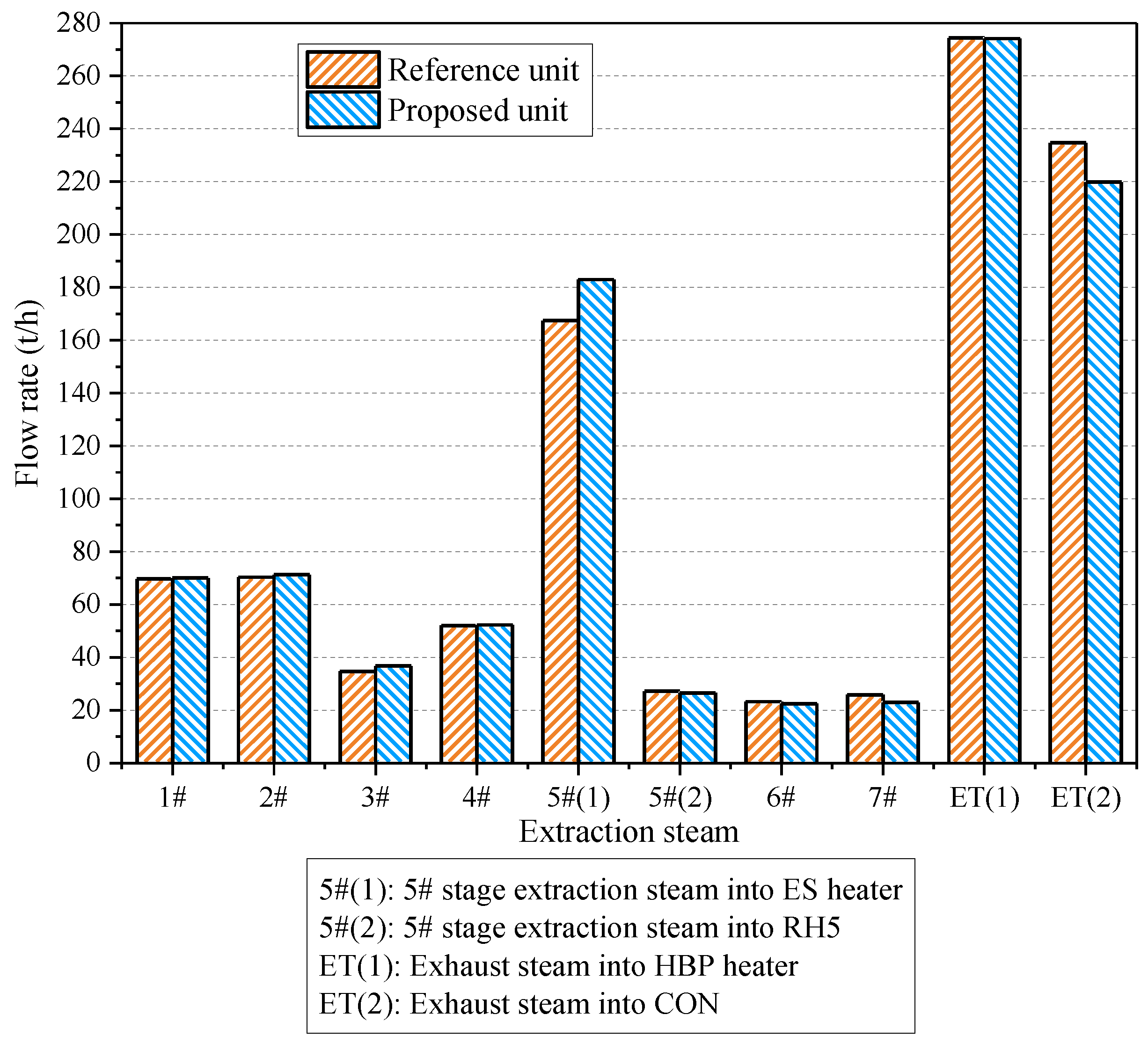
| Extraction steam at ES heater inlet | Flow rate (t/h) | 167.5 | 183.0 | +15.5 |
| Pressure (MPa) | 0.39 | 0.09 | −0.30 | |
| Temperature (°C) | 247.6 | 129.1 | −118.5 | |
| Specific enthalpy (kJ/kg) | 2959.9 | 2735.8 | −224.1 | |
| Saturation temperature (°C) | 142.7 | 96.7 | −46.0 | |
| Condensate at ES heater outlet | Pressure (MPa) | 0.39 | 0.09 | −0.30 |
| Temperature (°C) | 75.0 | 75.0 | 0 | |
| Specific enthalpy (kJ/kg) | 314.2 | 314.0 | −0.2 | |
| Exhaust steam | Total flow rate (t/h) | 509.1 | 494.0 | −15.1 |
| Flow rate into HBP heater (t/h) | 274.4 | 274.4 | 0 | |
| Flow rate into CON (t/h) | 234.7 | 219.6 | −15.1 | |
| Energy loss in CON (MW) | 144.3 | 135.3 | −9.0 | |
| Recovery efficiency (%) | 53.90 | 55.49 | +1.59 | |
| Net heat output (MW) | 300.0 | 300.0 | 0 | |
| Net power output attributed to HPT, IPT and LPT (MW) | 248.4 | 247.9 | −0.5 | |
| Net power output attributed to AT (MW) | 0 | 8.9 | +8.9 | |
| Total net power output (MW) | 248.4 | 256.8 | +8.4 | |
| Energy utilization factor (%) | 70.26 | 71.34 | +1.08 | |
| Artificial thermal efficiency (%) | 59.27 | 61.28 | +2.01 | |
| Equipment | Unit | Capital Investment |
|---|---|---|
| Additional turbine | million USD | |
| Additional generator | million USD |
| Item | Nov. | Dec. | Jan. | Feb. | Mar. | |
|---|---|---|---|---|---|---|
| Heating time (day) | 15 | 31 | 31 | 28 | 15 | |
| Net heat output (MW) | 173.5 | 271.3 | 309.7 | 304.4 | 198.7 | |
| Supply water temperature (°C) | 77 | 83 | 89 | 86 | 80 | |
| Return water temperature (°C) | 44 | 46 | 48 | 47 | 45 | |
| Reference unit | Net power output (MW) | 164.1 | 212.2 | 251.8 | 245.7 | 168.5 |
| Energy utilization factor (%) | 65.41 | 72.55 | 70.52 | 71.16 | 68.94 | |
| Artificial thermal efficiency (%) | 53.43 | 62.49 | 59.52 | 60.47 | 57.46 | |
| Proposed unit | Net power output (MW) | 167.1 | 219.1 | 261.7 | 254.3 | 172.7 |
| Net power output increment (MW) | 2.9 | 7.0 | 9.9 | 8.6 | 4.1 | |
| Energy utilization factor (%) | 65.97 | 73.62 | 71.82 | 72.31 | 69.73 | |
| Artificial thermal efficiency (%) | 54.39 | 64.61 | 61.97 | 62.67 | 58.91 | |
| Item | Unit | Value |
|---|---|---|
| Total capital investment () | million USD | 4.07 |
| Annual operation and maintenance cost () | million USD | 0.16 |
| Net annual earning () | million USD | 2.02 |
| Dynamic payback period (DPP) | year | 2.82 |
| Net present value (NPV) | million USD | 22.76 |
© 2019 by the authors. Licensee MDPI, Basel, Switzerland. This article is an open access article distributed under the terms and conditions of the Creative Commons Attribution (CC BY) license (http://creativecommons.org/licenses/by/4.0/).
Share and Cite
Chen, H.; Wu, Y.; Xu, J.; Xu, G.; Yang, Y.; Liu, W.; Shi, G. Thermodynamic and Economic Analyses of Reformative Design for High Back-Pressure Heating in Coal-Fueled Cogeneration Units. Entropy 2019, 21, 342. https://doi.org/10.3390/e21040342
Chen H, Wu Y, Xu J, Xu G, Yang Y, Liu W, Shi G. Thermodynamic and Economic Analyses of Reformative Design for High Back-Pressure Heating in Coal-Fueled Cogeneration Units. Entropy. 2019; 21(4):342. https://doi.org/10.3390/e21040342
Chicago/Turabian StyleChen, Heng, Yunyun Wu, Jidong Xu, Gang Xu, Yongping Yang, Wenyi Liu, and Gangye Shi. 2019. "Thermodynamic and Economic Analyses of Reformative Design for High Back-Pressure Heating in Coal-Fueled Cogeneration Units" Entropy 21, no. 4: 342. https://doi.org/10.3390/e21040342