Multi-Objective Optimization for Solid Amine CO2 Removal Assembly in Manned Spacecraft

1
School of Aeronautic Science and Engineering, Beijing University of Aeronautics and Astronautics, Beijing 100191, China
2
Beijing Spacecrafts, Beijing 100094, China
*
Author to whom correspondence should be addressed.
Entropy 2017, 19(7), 348; https://doi.org/10.3390/e19070348
Submission received: 5 February 2017
/
Revised: 7 June 2017
/
Accepted: 8 July 2017
/
Published: 10 July 2017
(This article belongs to the Special Issue Work Availability and Exergy Analysis)
Abstract
:Carbon Dioxide Removal Assembly (CDRA) is one of the most important systems in the Environmental Control and Life Support System (ECLSS) for a manned spacecraft. With the development of adsorbent and CDRA technology, solid amine is increasingly paid attention due to its obvious advantages. However, a manned spacecraft is launched far from the Earth, and its resources and energy are restricted seriously. These limitations increase the design difficulty of solid amine CDRA. The purpose of this paper is to seek optimal design parameters for the solid amine CDRA. Based on a preliminary structure of solid amine CDRA, its heat and mass transfer models are built to reflect some features of the special solid amine adsorbent, Polyethylenepolyamine adsorbent. A multi-objective optimization for the design of solid amine CDRA is discussed further in this paper. In this study, the cabin CO2 concentration, system power consumption and entropy production are chosen as the optimization objectives. The optimization variables consist of adsorption cycle time, solid amine loading mass, adsorption bed length, power consumption and system entropy production. The Improved Non-dominated Sorting Genetic Algorithm (NSGA-II) is used to solve this multi-objective optimization and to obtain optimal solution set. A design example of solid amine CDRA in a manned space station is used to show the optimal procedure. The optimal combinations of design parameters can be located on the Pareto Optimal Front (POF). Finally, Design 971 is selected as the best combination of design parameters. The optimal results indicate that the multi-objective optimization plays a significant role in the design of solid amine CDRA. The final optimal design parameters for the solid amine CDRA can guarantee the cabin CO2 concentration within the specified range, and also satisfy the requirements of lightweight and minimum energy consumption.
1. Introduction
Atmosphere composition control is important for astronaut life safety and health in a manned spacecraft [1]. CO2 removal technology can maintain cabin CO2 concentration level, always meeting the specified requirements. With the development of manned space activities, researchers investigated and evolved various CO2 removal techniques to adapt different missions, such as Lithium Hydroxide (LiOH) [2], molecular sieve [3,4], solid adsorbents [5,6] and membrane separation [7], etc. The LiOH canister has long been used in early missions (e.g., Mercury, Gemini and Apollo space capsules) due to its reliable, simple and effective performance to satisfy a short mission requirement [8]. However, the LiOH canister only removes CO2 without regeneration, so its whole weight of non-regeneration system may be heavier than the one of regeneration system along with the extension of mission time. For a long-term space mission, such as the International Space Station (ISS) [4], the 4-Bed Molecular Sieve (4-BMS) Carbon Dioxide Removal Assembly (CDRA) shows a very good working performance. Although the 4-BMS CDRA is considered more mature than the others, it consumed 497 W average energy and 871 W highest energy, which was a heavy energy burden for the ISS [9]. In addition, the membrane separation technology seems to be an alternative CDRA method, but the lack of selectivity between CO2 and oxygen has long perplexed researchers. The future CDRA needs to be more efficient to fulfill the requirement of lower CO2 partial pressure. Different alternative technologies need to be developed to overcome these problems.
At present, CO2 removal technology mainly adopts the zeolite and silica gel adsorbent adsorption method in manned spacecraft. In comparison, a solid amine CDRA has superior features, such as low energy consumption, small volume and lightweight. Hence, it is widely applied in submarines [10], space shuttles [11], and manned spacecraft [11,12,13,14].
In early research, the solid amine CDRA became a competitive method in the United States and Russia [15]. Germany developed its corresponding solid amine products [11]. The European Space Agency (ESA) and Japan also studied the solid amine CDRA for their Environmental Control and Life Support System (ECLSS) in the International Space Station (ISS) [13,16]. Many researchers developed experimental prototypes of solid amine adsorption and vapor desorption, such as IRA-45 in the United States, DORSA-028 in Germany, DIAION WA-21 in Japan [11,17].
In this paper, a solid amine CDRA using the Polyethylenepolyamine adsorbent is designed preliminarily. In order to obtain the optimal design parameters for the studied solid amine CDRA, a multi-objective optimization for solid amine CDRA will be developed to realize its minimization of mass, volume and power consumption.
2. Working Principle for Solid Amine CDRA
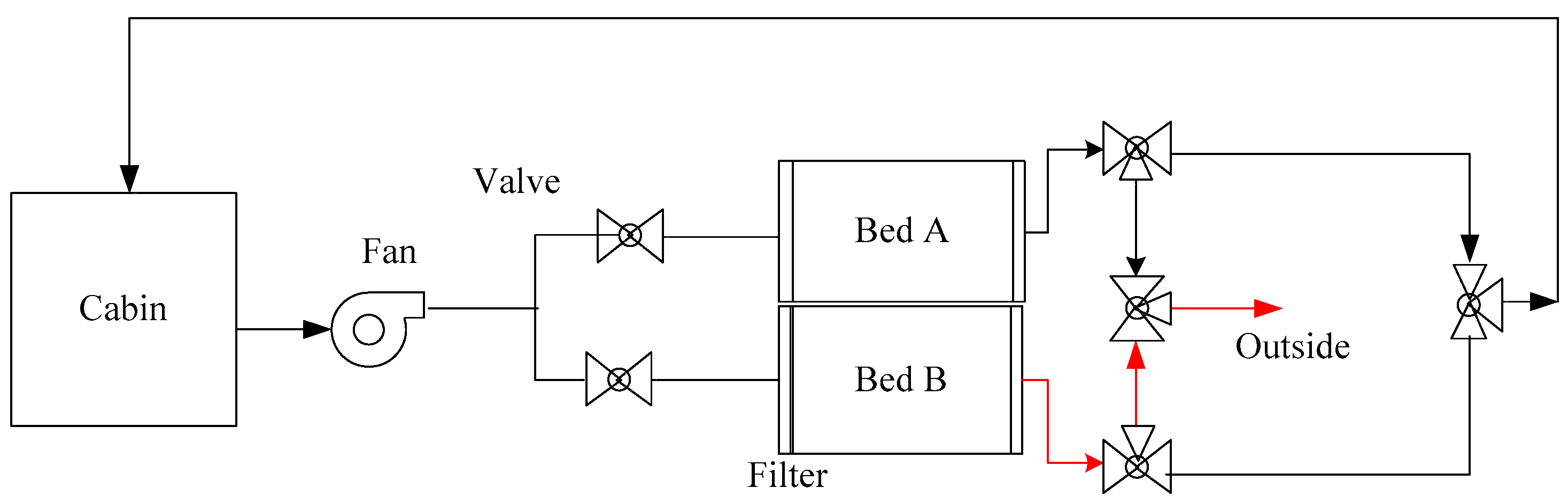
According to our study results of previous thermo-gravimetric experiments and adsorption bed experiments, a suitable adsorption temperature for Polyethylenepolyamine is 10–30 °C, and the desorption temperature is above 45 °C at vacuum condition. Based on the above results, the solid amine CDRA is designed as shown in Figure 1.
The cabin air with CO2 and water vapor is driven by a fan into the solid amine CDRA. Two beds are at the outlet of the fan. Bed A adsorbs CO2 and water vapor, and generates the adsorption heat, which is transferred to Bed B. At the same time, Bed B desorbs CO2 and water vapor to vacuum space under the effect of adsorption heat.
The designation of the solid amine CDRA system aims to keep the cabin CO2 concentration within the specified concentration requirement. Besides, the system should have both economical thermodynamic performance and good mechanical features, such as lightweight, small size, low energy consumption and easy-maintainability, low noise and vibration prevention. The thermodynamic factor is mainly concerned in our study. It is difficult to reasonably design this solid amine CDRA with so many constraints, hence a multi-objective design optimization for the solid amine CDRA in a manned spacecraft will be developed this paper.
3. Mechanism Models
3.1. Heat and Mass Transfer Models for Adsorption Process
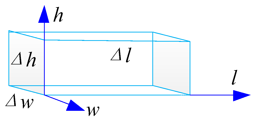
A rectangular structure for a bed is adopted in our study. The two adsorption beds are designed to be close together so that adsorption heat from one bed can be fully transferred to the other bed for the desorption. This design can rapidly cool the adsorption bed, and also fully use the heat energy. Many researchers set up dynamical models for different solid amine structures [18,19,20,21,22,23,24,25,26,27,28]. In this paper, we focus to set up heat and mass transfer models for a rectangular bed structure. A differential control volume of adsorption bed is shown in Figure 2. The heat and mass transfer process will happen along the directions of length l, width w and height h.
1. Mass transport model
Assume that the gas phase is uniform in the w and h directions, and then the mass change in the control volume can be simplified as:
where Cg is the CO2 concentration in the adsorption bed, kg/m3; is the time, s; Deff,l is the axial diffusion coefficient along the length direction, m2/s; l is the length direction, m; ρs is the density of the particle of solid amine, kg/m3; u is the air velocity inside the adsorption bed, m/s; qads is the amount of adsorbed CO2, kg/kg; is the bed void, m3/m3.
The instantaneous adsorption capacity can be calculated as:
where is the gas-phase concentration of CO2 in bulk flow, kg/m3; k is the overall mass transfer coefficient, 1/s; qequ is the amount of equilibrium adsorption loading, kg/kg; K is the Henry’s constant, m3/kg.
2. Heat transfer model
(1) Heat transfer equation for the gas phase
If the heat diffusion along the w and h directions can be neglected, the heat transfer in the gas phase can be written in Equation (3) according to the energy conservation:
where ρg is the density of gas phase, kg/m3; Cp,g is the specific heat capacity of gas phase, J/(kg·K); Tg is the temperature of gas phase, K; kf,l is the effective thermal conductivity of gas phase in the direction of l, W/(m·K); hf is the convective heat transfer coefficient between the gas phase and the solid amine particles, W/(m2·K); as is the specific external surface area of the solid amine particles in the bed per unit volume, m2/m3; Ts is the temperature of solid phase, K; W, L and H are the width, length and height of the adsorption bed, respectively, m; hw is the convective heat transfer coefficient between the gas phase and the internal surface of bed, W/(m2·K); Tw is the internal wall temperature of bed, K.
The initial and boundary conditions are as follows:
where Tg,0 is the initial temperature of gas phase, K.
(2) Heat transfer equation for the solid phase
If the heat diffusion along the l direction can be neglected, then the heat transfer equation can be simplified in Equation (4):
The initial and boundary conditions of solid phase are as follows:
where ρs is the density of solid, kg/m3; Cp,s is the heat capacity of solid, J/(kg·K); Ts and Ts,0 are the solid temperature and its initial value, respectively, K; ΔH is the adsorption heat, J/mol; ρi is the density of ith adsorbed component, kg/m3; Mi is the molecular weight of ith adsorbed component, kg/mol; i represents CO2 and water vapor; hs is the heat transfer coefficient between solid and gas, W/(m2·K); ks,l is the effective thermal conductivity of solid in the l direction, W/(m·K).
(3) Heat transfer equation for the wall of adsorption bed
As shown in Figure 1, the wall temperature of Bed A is greatly impacted by the gas and solid phase temperatures in Bed A. The heat exchange of Bed A with Bed B is determined by the heat diffusion and convective heat transfer along the w direction, so the heat transfer equation for the wall can be as follows:
The initial condition is below:
where ρw is the density of wall, kg/m3; Cp,w is the heat capacity of wall, J/(kg·K); Tw and Tw,0 are the wall temperature and its initial value, respectively, K; hw is the heat transfer coefficient between the gas and the wall, W/(m2·K); ks,w is the effective thermal conductivity of solid in w direction, W/(m·K).
(4) Heat transfer equation for the solid phase in the desorption bed
In a desorption bed, its solid amine is heated by the adsorption heat from another bed through the bed wall. The heat transfer process mainly depends on the heat conduction of solid phase in a vacuum environment. Assume that the heat conduction along the h direction is uniform, and then the temperature change can be calculated as below:
The corresponding boundary conditions are as follows:
where Ts,2 and Ts,20 are the solid temperature and its initial value in the desorption condition, respectively, K.
3.2. Cabin CO2 Concentration
The cabin CO2 concentration can be calculated when the cabin volume is fixed:
where is the cabin CO2 concentration, kg/m3; VC is the cabin volume, m3; is the CO2 generation rate by crew, kg/s; and are the CO2 generation rate at the inlet and outlet of CDRA, respectively, kg/s.
The terms, , and , can be obtained from Equations (8)–(10), respectively.
where n is the numbers of crew; δ is the mass rate of CO2 generation, kg/s; and are the CO2 concentrations at the outlet and inlet of absorption bed, kg/m3; Vm is the volume flow rate, m3/s.
3.3. Power Consumption
For the solid amine CDRA, its power consumption happens in two components, the fan and the saving pump. The power consumption of the saving pump is constant and determined by the desorption pressure. The power of the fan is calculated by the pressure drop and the volume flow rate as follows:
where is the power of the fan, J/s; η is the fan efficient, %; is the pressure difference between the inlet and outlet of the fan, Pa; Vm is the inlet volume flow rate of the fan, m3/s.
3.4. Entropy Generation
Two solid amine packed beds are the primary components for this type of CDRA. A detailed component-by-component entropy generation analysis is highly important for the design of CDRA. According to the working principle illustrated in Section 2, Bed A and Bed B alternatively adsorb CO2. Thus, the entropy generation analysis will be conducted in a half-cycle. The entropy generation rate of the adsorption bed can be calculated as follows [29,30]:
where is the entropy generation rate of adsorption bed, J/(K·s); τad is the half-cycle time of solid amine CDRA, s; mmat is the mass of packed bed materials, kg; Cp,mat is the specific heat capacity of packed bed materials, J/(kg·K); ms is the mass of solid amine particles, kg; is the mass flow rate of gas phase, kg/s; sg,out and sg,in are the outlet and inlet specific entropy values of gas phase, J/(kg·K).
The first term on the right side of Equation (12) represents the entropy change due to temperature variation of packed bed materials, solid amine particle adsorbent and the adsorbed adsorbates. The second term denotes the entropy change contribution of gas phase flashing through the adsorption bed.
The desorption process is particularly conducted in a vacuum space state. Its entropy can be considered to be a constant value. The entropy generation rate of desorption bed, , can be written as [29]:
During the adsorption and desorption processes, the temperature change is mainly caused by the reaction heat between CO2 and solid amine, and this will lead to the entropy productions. The following assumptions are made in the analysis:
- (1)
- The heat losses of two beds are disregarded, so the filter is considered as an isothermal system.
- (2)
- The effect of CO2 mass in both gas phase and adsorbent can be ignored.
- (3)
- The pressure is assumed to be constant.
- (4)
- The gas phase is assumed to obey the ideal gas behavior.
On the basis of the above assumptions, the entropy generation rates of adsorption and desorption beds can be described by the following equations:
where Tg,out is the outlet temperature of gas phase, K; Ts,des is the desorption temperature of solid amine, K; T0 is the environmental temperature, K.
3.5. Numerical Calculation Method
The heat and mass transfer models are calculated using the numerical method in Matlab program. In the calculation of mass transfer model, the time step is 0.01 h and the space step along the l direction is 0.01 m. As for the heat transfer equations, the time step is 0.003 h and the space step along the l and w directions is 0.01 m. The corresponding parameters in the optimization analysis are shown in Table 1.
4. Multi-Objective Optimization for the Solid Amine CDRA
4.1. Optimization Objectives and Variables
The design objectives of solid amine CDRA optimization include the following parameters:
- (1)
- Cabin CO2 concentration should be controlled within the allowed range and kept at minimum, min (CCO2);
- (2)
- Minimize the fan power consumption, min (WFan);
- (3)
- Minimize the entropy generation in the adsorption bed, min (Sg,ads);
- (4)
- Maximize the difference of entropy generations in the adsorption and desorption beds, max (dSg), where dSg = Sg,des − Sg,ads.
Therefore, this multi-objective optimization includes four objectives as follows:
expresses the vector of four optimization variables:
4.2. Constraints for Optimization
- Constraints of optimal objectives
- (1)
- (2)
- The heat adsorption process is irreversible, so Sg,ads > 0 and dSg > 0.
- Constraints of optimization variables
- (1)
- The parameters, L and u, should satisfy the law of momentum conservation:
- (2)
- ms should be less than the maximum loading mass in the absorption bed:
- (3)
- τad should be less than the time when the adsorption reaches its saturation state:
- (4)
- The desorption condition is kept at a vacuum state over 1.5 h:
According to the solid amine adsorption capacity and the specific shape of adsorbent bed, the ranges of four optimization variables are set as follows:
4.3. Calculation Methods of Optimization
In this paper, the optimization method is established by using Modefrontier software and Matlab software together. The heat and mass transfer models are programmed in M-file of Matlab and NSGA-II is selected in Modefrontier software to obtain optimal results.
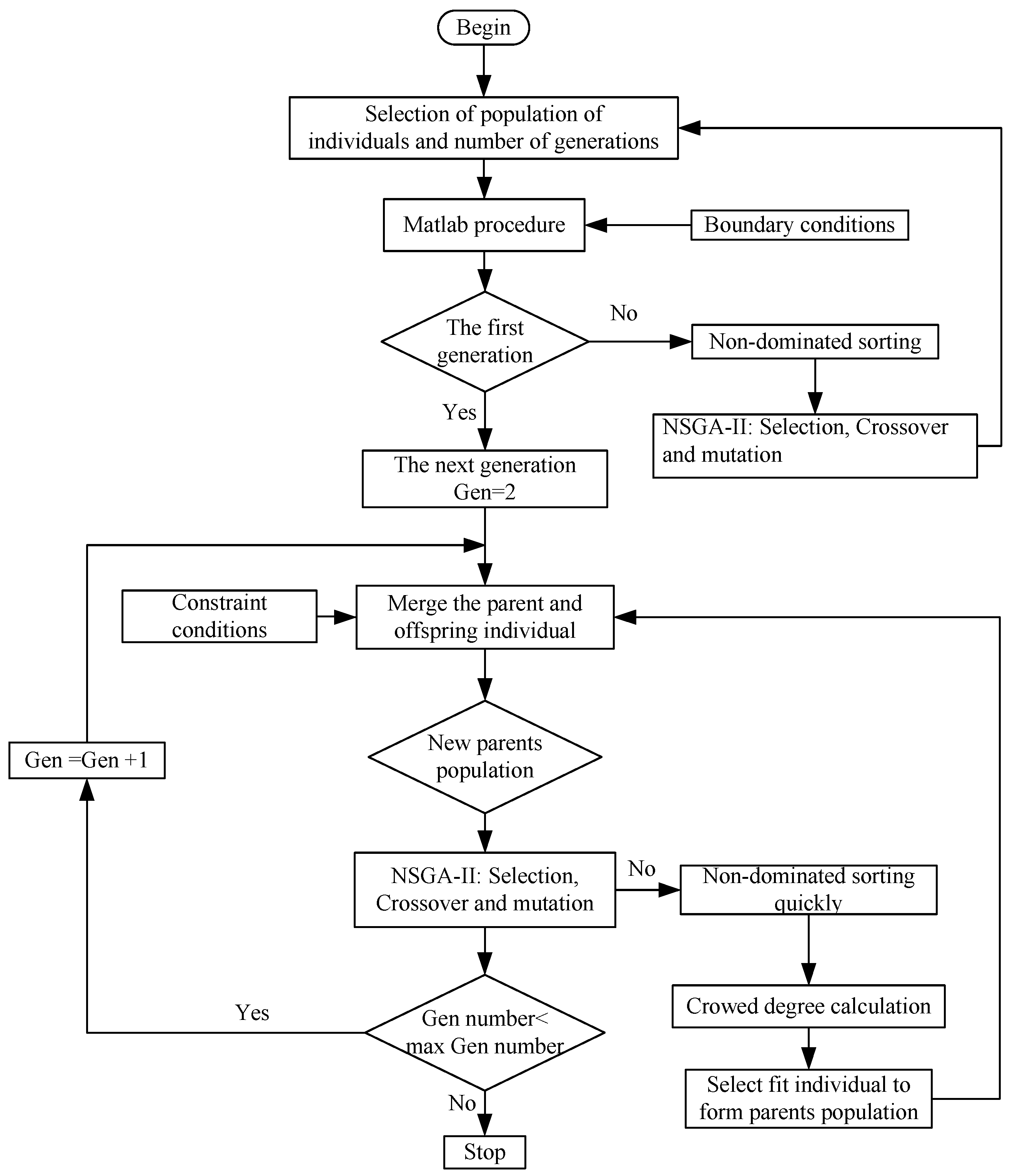
The optimization procedure is shown in Figure 3. A number of initial populations are generated in this algorithm. The population goes through non-dominated sorting, selection, simulated binary crossover and polynomial mutation, and then the first generation is obtained. Appropriate individuals are selected as parent population according to the crowding degree, and then produce a new offspring population through basic operation of genetic algorithm. Parent population and offspring population are combined from the second generation, and the crowding degree for individual in non-dominant layer is calculated [32]. Cycles will continue in turn until the optimum result appears. In this method, the excellent populations will not be discarded in the evolution, and the precision of the optimization results can be improved by storing all the hierarchical individuals in the population [33,34].
5. Multi-Objective Optimal Results
5.1. Parameters for NSGA-II
Pareto optimal solutions can be obtained by using the above optimal method. The corresponding parameters for NSGA-II are listed in Table 2. The number of initial population is 20, which will go through the selection, crossover and mutation. Finally, the proper individuals for multi-objective function can be obtained.
5.2. Pareto Optimal Solution Set
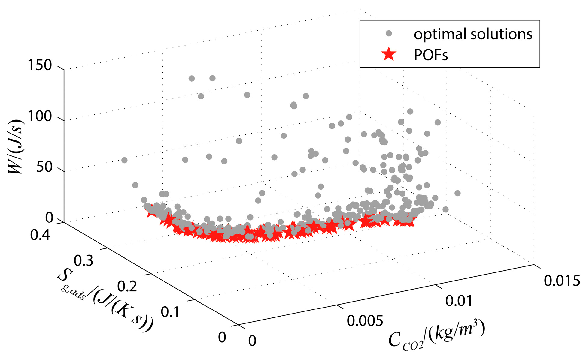
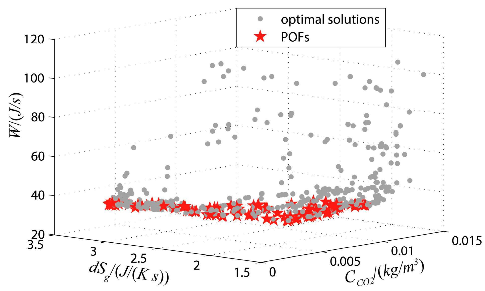
A curved surface and POFs will be formed when the solution set is mapped onto the coordinate system. Figure 4 shows the three-dimensional relationship between Sg,ads, and WFan. Figure 5 displays the relationship between Sg,ads, and dSg. Both the two figures show the distribution of optimal solutions. In Figure 4, the optimal values are located near to the minimum values of three objectives. In Figure 5, the optimal values are located near to the minimum values of and WFan, and the maximum values of dSg.
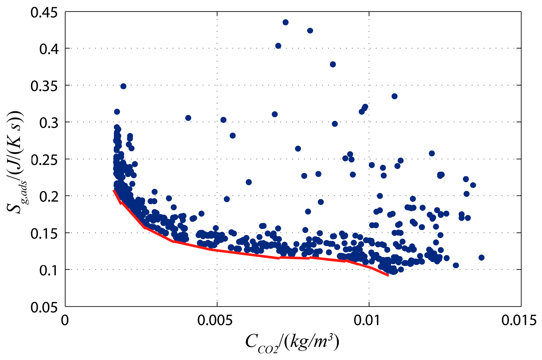
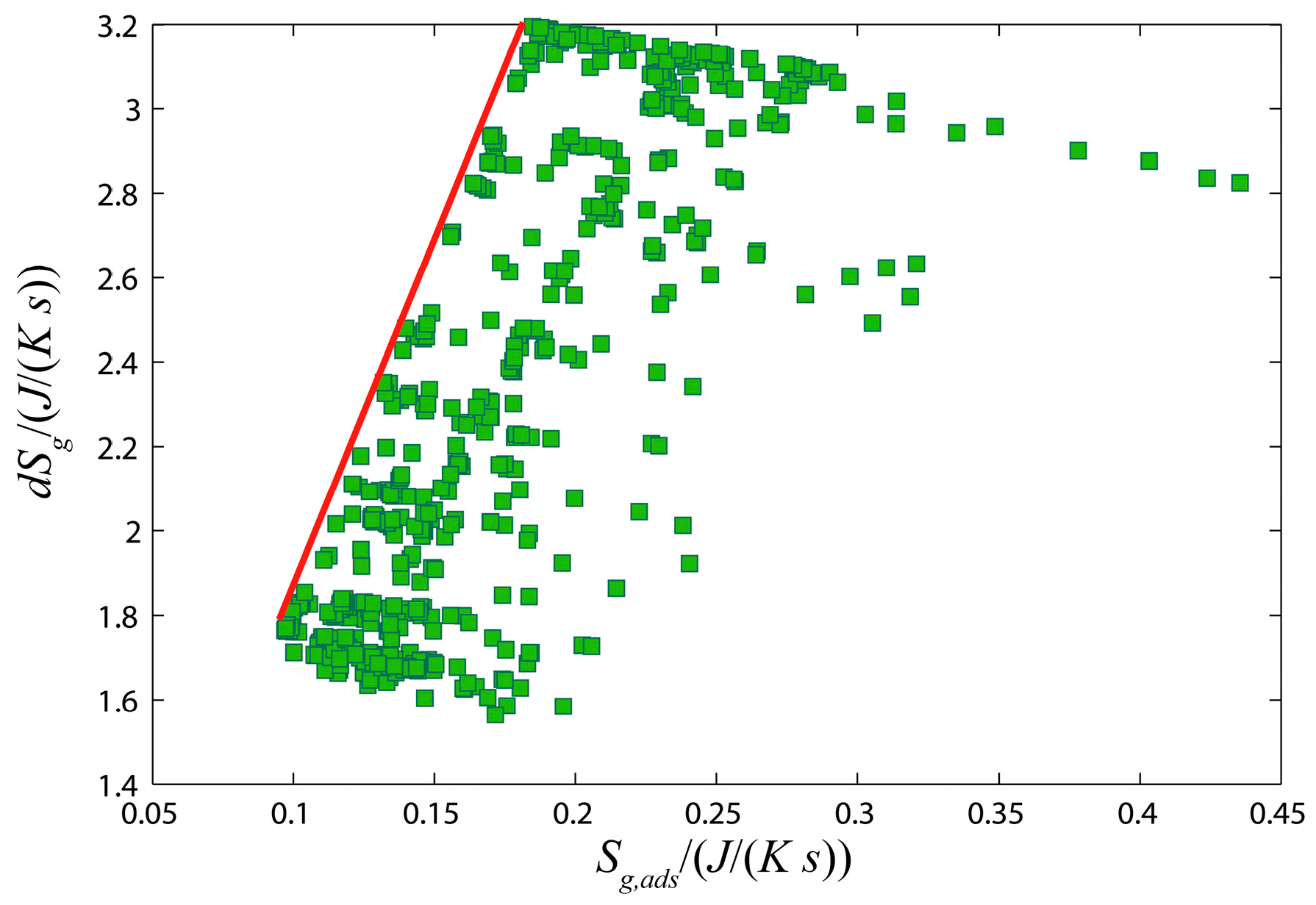
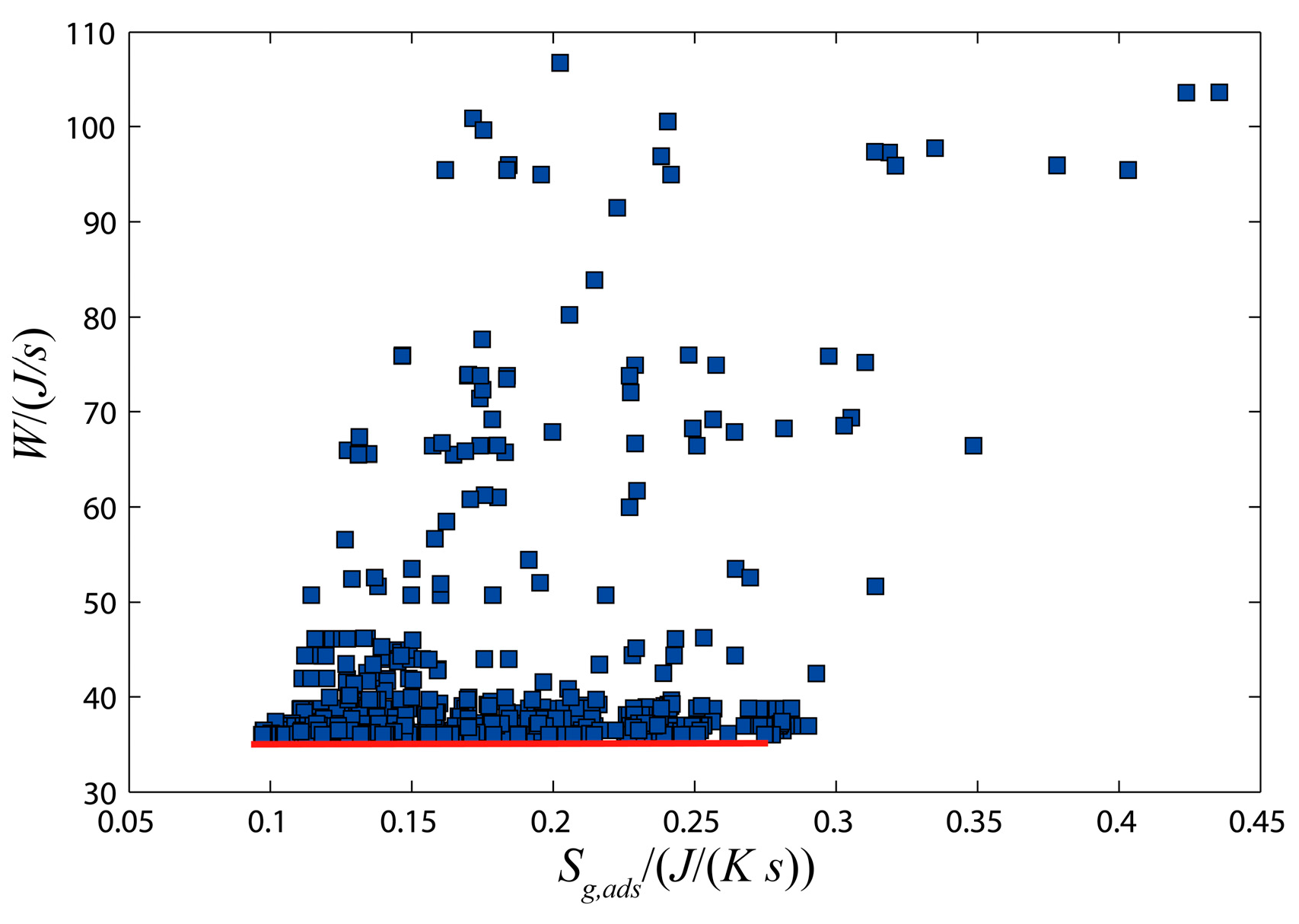
In order to describe the relationship of our optimization objectives obviously, the optimization relationships are shown in Figure 6, Figure 7 and Figure 8, respectively. The red lines in these figures show the potential POFs of the solution set.
- (1)
- In Figure 6, the maximum value of is 0.0137 kg/m3, about 0.69% volume concentration, which means that all the values of CCO2 satisfy the requirement. The optimal values can be derived from the POFs. The potential optimal combinations of design parameters include Designs 228, 461, 649, 759, 885, 930, 971, 1017, 1129, 1172, 1332, 1430, 1644, 1686, 1758, 1834, 1915, 1985 and 1993.
- (2)
- Figure 7 shows the optimal relationship between min (Sg,ads) and max (dSg). The potential optimal design points on the POFs include Designs 461, 649, 930, 971, 1008, 1017, 1332, 1430, 1481, 1635, 1644, 1686, 1829, 1834, 1915, 1974 and 1985.
- (3)
- In Figure 8, the preferred points contained Designs 228, 461, 540, 649, 885, 930, 971, 1008, 1017, 1260, 1332, 1430, 1556, 1644, 1686, 1751, 1829, 1915, 1985 and 1993.
The optimal combinations of design parameters can be selected from the intersection of the above three optimal points sets, and they are listed in Table 3.
In Table 3, air velocity values tend to its lower limit, which indicates that a low velocity is beneficial to optimal results. Besides, the relationship between u and WFan is almost a linear one. The low velocity will lead to a reduction of volume flow rate, and then reduce the fan power consumption. However, the low velocity is not conducive to the convective heat transfer between gas phase and solid phase. The increase of bed length will prolong the penetration time. It is conducive to reduce CCO2 and increase the heat transfer area. Meanwhile, the resistance will be increased, which will lead to the increase of the fan power consumption.
Particularly, τad has a significant impact on dSg and Sg,ads. dSg and Sg,ads will increase with the reducing of τad. The POFs show an approximate linear relation between dSg and τad. The CO2 concentration and the fan power seem to be scarcely affected by τad, as shown in Figure 9.
5.3. Optimal Solution for CDRA
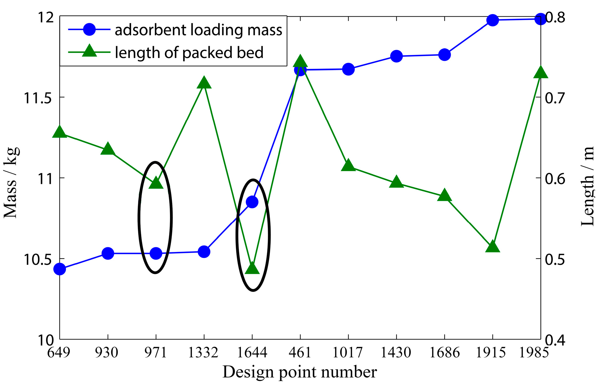
Without additional subjective preference information, all Pareto solutions listed in Table 3 are considered to be equal. When a design of a CDRA system is conducted for a manned spacecraft, a single design point should be selected form the optimal results. In addition, for the sake of reducing the cost of launch and operation, each design combination of optimal variables should be selected in view of many considerations, such as lightweight, small volume, easy-maintainability, power consumption, and so on. Figure 10 shows the comparison of adsorbent loading mass and the bed length based on the obtained optimal results in Table 3. The circled two points in Figure 10 meet the requirement of lighter weight and smaller volume. These two design points seem to be the optimization points. According to the parameters listed in Table 3, Design 1644 shows the less Sg,ads and greater dSg than Design 971. However, the CO2 concentration value of Design 1644 is 0.00976 kg/m3, that is, 0.497% vol/vol, which is really higher than the one of Design 971. Thus, Design 971 is finally determined as the preferred design group.
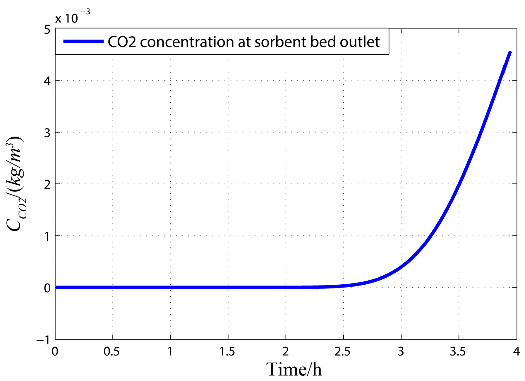
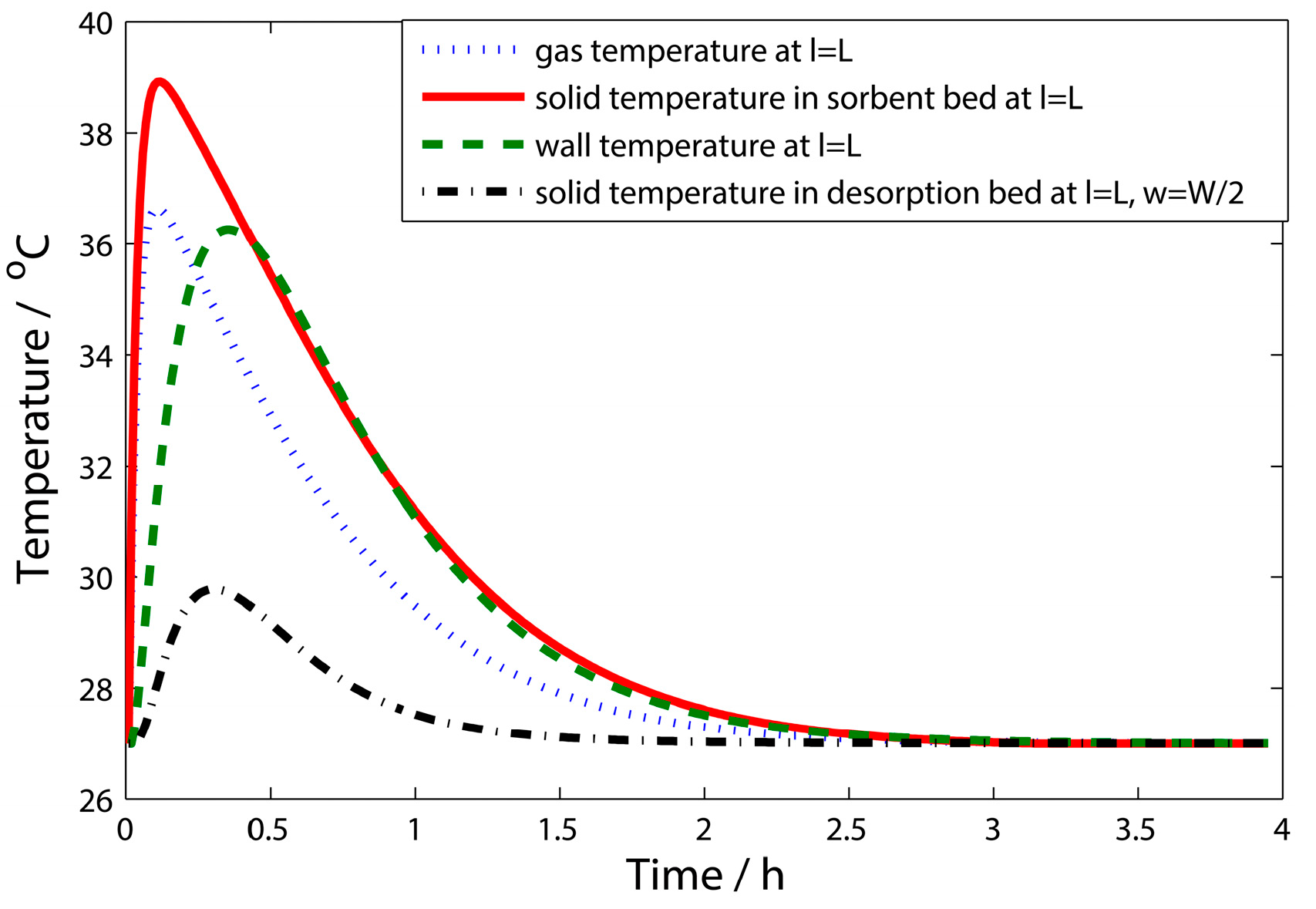
For the CDRA system design based on the parameters of Design 971, the outlet CO2 concentration of the adsorption bed is simulated as shown in Figure 11. The temperature change of gas, solid and wall at l = L with time, as well as the desorption temperatures at l = L and w = W/2, are shown in Figure 12.
From Figure 11, the half-cycle time of the absorption bed is 3.94 h, but the adsorption saturation is reached at about 4 h. Thus, the cabin CO2 concentration can always be maintained within the requirements. All temperatures in Figure 12 rise rapidly because of the adsorption heat. The highest temperature of solid phase in the adsorption bed can reach 38.9 °C, and the peak value of gas temperature is 36.6 °C. The solid amine in the desorption bed also increases to 30 °C. In order to realize a complete desorption condition, the temperature in the desorption bed needs to reach more than 45 °C. It is obvious that the adsorption heat is not enough for the desorption process, thus, some improvement methods should be considered to meet the requirement of desorption heat.
6. Conclusions
A multi-objective optimization is studied in this paper for the design of solid amine CDRA in manned spacecraft. CCO2, WFan, Sg,ads and dSg, are chosen as objective functions. u, L, τad and ms are confirmed as optimal design variables. The mass and heat transfer models are set up for the solid amine CDRA. NSGA-II is used to solve the multi-objective optimal process subject to constraints. The POF can be located and the optimal designs can be searched. With our study, the following conclusions can be drawn:
- Small loading mass of ms is beneficial to reduce the system weight and total pressure difference, but it is a disadvantage to ;
- τad has approximate linear relationship with dSg, but it is inversely proportional to Sg,ads and dSg;
- The increase of L contributes to increase the heat transfer surface and improves the adsorption capacity, but it will lead to the entropy generation in the desorption bed;
- The low velocity leads to reducing the power consumption, but it is not conducive to the convective heat transfer between the gas and solid phase.
Design 971 is finally selected as the final optimal combinations of design parameters. The CO2 concentration and temperature changes of Design 971 are calculated. They can reflect the adsorption process in the bed. One point needs to notice that some enhanced heat transfer methods should be considered in the design of solid amine CDRA because the heat conduction is not enough to reach its desorption temperature.
Acknowledgments
The authors are grateful to the anonymous reviewers for their critical and constructive review of the manuscript. Their comments helped to increase quality and readability of the manuscript. This work was supported by the Open Funding Project of National Key Laboratory of Human Factors Engineering (No. SYFD14005181K).
Author Contributions
All authors contributed equally to this article. The theoretical aspect of this work does not allow to point to any substantial authorship. All authors have read and approved the final manuscript.
Conflicts of Interest
The authors declare no conflict of interest.
References
- Mulloth, L.M.; Finn, J.E. Air quality systems for related enclosed spaces: Spacecraft air. In Air Quality in Airplane Cabins and Similar Enclosed Spaces; Hocking, M., Ed.; Springer: Berlin/Heidelberg, Germany, 2005; pp. 383–404. [Google Scholar]
- Williams, D.E.; Pate, L.R.; Hoffman, C. The lithium hydroxide management plan for removing carbon dioxide from the space shuttle while docked to the international space station. SAE Int. 2003. [Google Scholar] [CrossRef]
- Gomes, V.G.; Yee, K.W.K. Pressure swing adsorption for carbon dioxide sequestration from exhaust gases. Sep. Purif. Technol. 2002, 28, 161–171. [Google Scholar] [CrossRef]
- Matty, C. Overview of carbon dioxide control issues during international space station/space shuttle joint docked operations. In Proceedings of the 40th International Conference on Environmental Systems, American Institute of Aeronautics and Astronautics, Barcelona, Spain, 11–15 July 2010. [Google Scholar]
- Knox, J.; Gostowski, R.; Watson, D.; Hogan, J.; King, E.; Thomas, J. Development of carbon dioxide removal systems for advanced exploration systems. In Proceedings of the 42nd International Conference on Environmental Systems, American Institute of Aeronautics and Astronautics, San Diego, CA, USA, 15–19 July 2012. [Google Scholar]
- Papale, W.; Nalette, T.; Sweterlitsch, J. Development status of the carbon dioxide and moisture removal amine swing-bed system (camras). SAE Tech. Pap. 2009. [Google Scholar] [CrossRef]
- Ebner, A.D.; Ritter, J.A. State-of-the-art adsorption and membrane separation processes for carbon dioxide production from carbon dioxide emitting industries. Sep. Sci. Technol. 2009, 44, 1273–1421. [Google Scholar] [CrossRef]
- Isobe, J.; Henson, P.; MacKnight, A.; Yates, S.; Schuck, D.; Winton, D. Carbon Dioxide Removal Technologies for U.S. Space Vehicles: Past, Present, and Future. In Proceedings of the 46th International Conference on Environmental Systems, American Institute of Aeronautics and Astronautics, Vienna, Germany, 10–14 July 2016. [Google Scholar]
- Wieland, P.O. Living Together in Space: The Design and Operation of the Life Support Systems on the International Space Station; National Aeronautics and Space Administration, Marshall Space Flight Center: Huntsville, AL, USA, 1998.
- Boynton, C.K.; Colling, A.K. Solid amine CO2 removal system for submarine application. SAE Tech. Pap. 1983. [Google Scholar] [CrossRef]
- Preiss, H.; Breitling, W.; Funke, H. Regenerative CO2-control: A technology development for european manned space programs. SAE Tech. Pap. 1988. [Google Scholar] [CrossRef]
- Satyapal, S.; Filburn, T.; Trela, J.; Strange, J. Performance and properties of a solid amine sorbent for carbon dioxide removal in space life support applications. Energy Fuels 2001, 15, 250–255. [Google Scholar] [CrossRef]
- Nitta, K. An overview of japanese celss research activities. Adv. Space Res. 1987, 7, 95–103. [Google Scholar] [CrossRef]
- Boehm, A.M.; Ouellette, F.A. Chamber testing of CO2 removal systems using solid amines. SAE Tech. Pap. 1995. [Google Scholar] [CrossRef]
- Sherif, D.E.; Knox, J.C. International space station carbon dioxide removal assembly (iss cdra) concepts and advancements. SAE Tech. Pap. 2005. [Google Scholar] [CrossRef]
- Nalette, T.A.; Blaser, R.W.; Coleman, W.D.; Cusick, R.J. Development of an advanced solid amine humidity and CO2 control system for potential space station extravehicular activity application. SAE Tech. Pap. 1988. [Google Scholar] [CrossRef]
- Wood, P.C.; Wydeven, T. Stability of ira-45 solid amine resin as a function of carbon dioxide absorption and steam desorption cycling. SAE Tech. Pap. 1987. [Google Scholar] [CrossRef]
- Bollini, P.; Brunelli, N.A.; Didas, S.A.; Jones, C.W. Dynamics of CO2 adsorption on amine adsorbents. 2. Insights into adsorbent design. Ind. Eng. Chem. Res. 2012, 51, 15153–15162. [Google Scholar] [CrossRef]
- Andreoli, E.; Cullum, L.; Barron, A.R. Carbon dioxide absorption by polyethylenimine-functionalized nanocarbons: A kinetic study. Ind. Eng. Chem. Res. 2015, 54, 878–889. [Google Scholar] [CrossRef]
- Monazam, E.R.; Shadle, L.J.; Siriwardane, R. Performance and kinetics of a solid amine sorbent for carbon dioxide removal. Ind. Eng. Chem. Res. 2011, 50, 10989–10995. [Google Scholar] [CrossRef]
- Rezaei, F.; Webley, P. Optimum structured adsorbents for gas separation processes. Chem. Eng. Sci. 2009, 64, 5182–5191. [Google Scholar] [CrossRef]
- Monazam, E.R.; Shadle, L.J.; Miller, D.C.; Pennline, H.W.; Fauth, D.J.; Hoffman, J.S.; Gray, M.L. Equilibrium and kinetics analysis of carbon dioxide capture using immobilized amine on a mesoporous silica. AIChE J. 2013, 59, 923–935. [Google Scholar] [CrossRef]
- Wurzbacher, J.A.; Gebald, C.; Piatkowski, N.; Steinfeld, A. Concurrent separation of CO2 and H2O from air by a temperature-vacuum swing adsorption/desorption cycle. Environ. Sci. Technol. 2012, 46, 9191–9198. [Google Scholar] [CrossRef] [PubMed]
- Pirngruber, G.D.; Leinekugel-le-Cocq, D. Design of a pressure swing adsorption process for postcombustion CO2 capture. Ind. Eng. Chem. Res. 2013, 52, 5985–5996. [Google Scholar] [CrossRef]
- Puxty, G.; Rowland, R. Modeling CO2 mass transfer in amine mixtures: Pz-amp and pz-mdea. Environ. Sci. Technol. 2011, 45, 2398–2405. [Google Scholar] [CrossRef] [PubMed]
- Zhang, J.F.; Nwani, O.; Tan, Y.; Agar, D.W. Carbon dioxide absorption into biphasic amine solvent with solvent loss reduction. Chem. Eng. Res. Des. 2011, 89, 1190–1196. [Google Scholar] [CrossRef]
- Kim, M.; Song, H.J.; Lee, M.G.; Jo, H.Y.; Park, J.W. Kinetics and steric hindrance effects of carbon dioxide absorption into aqueous potassium alaninate solutions. Ind. Eng. Chem. Res. 2012, 51, 2570–2577. [Google Scholar] [CrossRef]
- Lee, S.; Filburn, T.P.; Gray, M.; Park, J.W.; Song, H.J. Screening test of solid amine sorbents for CO2 capture. Ind. Eng. Chem. Res. 2008, 47, 7419–7423. [Google Scholar] [CrossRef]
- Chua, H.T.; Ng, K.C.; Malek, A.; Kashiwagi, T.; Akisawa, A.; Saha, B.B. Entropy generation analysis of two-bed, silica gel-water, non-regenerative adsorption chillers. J. Phys. D 1998, 31, 1471. [Google Scholar] [CrossRef]
- Li, A.; Ismail, A.B.; Thu, K.; Ng, K.C.; Loh, W.S. Performance evaluation of a zeolite–water adsorption chiller with entropy analysis of thermodynamic insight. Appl. Energy 2014, 130, 702–711. [Google Scholar] [CrossRef]
- James, J.T. Carbon Dioxide. In Spacecraft Maximum Allowable Concentrations for Selected Airborne Contaminants; The National Academies Press: Washington, DC, USA, 2008; Volume 5, pp. 112–124. [Google Scholar]
- Lian, Y.S.; Oyama, A.; Liou, M.S. Progress in design optimization using evolutionary algorithms for aerodynamic problems. Prog. Aerosp. Sci. 2010, 46, 199–223. [Google Scholar] [CrossRef]
- Jeyadevi, S.; Baskar, S.; Babulal, C.K.; Iruthayarajan, M.W. Solving multiobjective optimal reactive power dispatch using modified nsga-ii. Int. J. Elecr. Power 2011, 33, 219–228. [Google Scholar] [CrossRef]
- Kannan, S.; Baskar, S.; McCalley, J.D.; Murugan, P. Application of nsga-ii algorithm to generation expansion planning. IEEE Trans. Power Syst. 2009, 24, 454–461. [Google Scholar] [CrossRef]
Figure 1.
Principle diagram of the solid amine Carbon Dioxide Removal Assembly (CDRA).

Figure 2.
Control volume of the solid amine adsorption bed.

Figure 3.
Optimization procedure. NSGA-II: Improved Non-dominated Sorting Genetic Algorithm.

Figure 4.
Optimal results for , Sg,ads and WFan.

Figure 5.
Optimal results for , dSg and WFan.

Figure 6.
Optimal results for and Sg,ads.

Figure 7.
Optimal results for dSg and Sg,ads.

Figure 8.
Optimal results for WFan and Sg,ads.

Figure 9.
Relationship between τad and objectives.

Figure 10.
Relationship between the adsorbent loading mass and the bed length.

Figure 11.
CO2 concentration at the adsorption bed outlet.

Figure 12.
Temperature changes of gas, solid and wall at l = L and w = W/2.


Table 1.
Related parameters in mass and heat transfer models.
| Parameter | Unit | Value | Parameter | Unit | Value |
|---|---|---|---|---|---|
| as | m2·m−3 | 520 | W·m−1·K−1 | 0.42 | |
| kg·m−3 | 5.45 × 10⁻⁴ | W·m−1·K−1 | 0.40 | ||
| J·kg−1·K−1 | 1.00 × 10³ | n | person | 3 | |
| J·kg−1·K−1 | 1000 | Pa | 800 | ||
| J·kg−1·K−1 | 900 | m3 | 118 | ||
| m2·s−1 | 1 × 10⁹ | ε | ---- | 0.35 | |
| H | m | 0.2 | T0 | K | 300 |
| hf | W·m−2·K−1 | 4.9 | Tg0 | K | 300 |
| hw | W·m−2·K−1 | 0.91 | Ts0 | K | 300 |
| ΔH | J·mol−1 | 5.75 × 10⁴ | W | m | 0.4 |
| K | m3·kg−1 | 5.65 | kg·m−3 | 1.2 | |
| k | h−1 | 3.9 × 10⁻² | kg·m−3 | 550 | |
| W·m−1·K−1 | 0.055 | kg·m−3 | 6500 | ||
| W·m−1·K−1 | 0.32 | Pa·s | 17.9 × 10⁻⁶ | ||
| W·m−1·K−1 | 1.39 | kg·h−1 | 4.15 × 10⁻² |
Table 2.
Parameters of the NSGA-II.
| Parameters | Value |
|---|---|
| Number of Designs | 20 |
| Number of Generations | 100 |
| Cross-Over Probability | 0.5 |
| Mutation Probability for Real-Coded Vectors | 1.0 |
| Mutation Probability for Binary Vectors | 1.0 |
| Distribution Index for Real-Coded Crossover | 20 |
| Distribution Index for Real-Coded Mutation | 20 |
| Random Generator Seed | 1 |
Table 3.
Optimal results of the solid amine CDRA.
| Design Point | u m/s | L m | τad h | ms kg | CCO2 kg/m3 | Sg,ads J/(s·K) | WFan J/s | dSg J/(s·K) |
|---|---|---|---|---|---|---|---|---|
| 461 | 0.10 | 0.74 | 3.64 | 11.67 | 0.00293 | 0.16 | 36.0 | 1.80 |
| 649 | 0.10 | 0.66 | 3.89 | 10.44 | 0.00458 | 0.13 | 36.0 | 1.70 |
| 930 | 0.10 | 0.63 | 3.94 | 10.53 | 0.00565 | 0.13 | 36.0 | 1.69 |
| 971 | 0.10 | 0.59 | 3.94 | 10.53 | 0.00703 | 0.12 | 36.0 | 1.69 |
| 1017 | 0.10 | 0.61 | 2.82 | 11.67 | 0.00234 | 0.17 | 36.0 | 2.31 |
| 1332 | 0.10 | 0.72 | 3.85 | 10.54 | 0.00350 | 0.14 | 36.0 | 1.71 |
| 1430 | 0.10 | 0.59 | 2.71 | 11.75 | 0.00226 | 0.18 | 36.0 | 2.40 |
| 1644 | 0.10 | 0.49 | 3.84 | 10.85 | 0.00976 | 0.11 | 36.0 | 1.75 |
| 1686 | 0.10 | 0.58 | 2.41 | 11.76 | 0.00200 | 0.20 | 36.0 | 2.67 |
| 1915 | 0.10 | 0.51 | 2.18 | 11.98 | 0.00186 | 0.20 | 36.0 | 2.93 |
| 1985 | 0.10 | 0.73 | 2.00 | 11.98 | 0.00169 | 0.27 | 36.0 | 3.11 |
© 2017 by the authors. Licensee MDPI, Basel, Switzerland. This article is an open access article distributed under the terms and conditions of the Creative Commons Attribution (CC BY) license (http://creativecommons.org/licenses/by/4.0/).
Share and Cite
MDPI and ACS Style
A, R.; Pang, L.; Liu, M.; Yang, D. Multi-Objective Optimization for Solid Amine CO2 Removal Assembly in Manned Spacecraft. Entropy 2017, 19, 348. https://doi.org/10.3390/e19070348
AMA Style
A R, Pang L, Liu M, Yang D. Multi-Objective Optimization for Solid Amine CO2 Removal Assembly in Manned Spacecraft. Entropy. 2017; 19(7):348. https://doi.org/10.3390/e19070348
Chicago/Turabian StyleA, Rong, Liping Pang, Meng Liu, and Dongsheng Yang. 2017. "Multi-Objective Optimization for Solid Amine CO2 Removal Assembly in Manned Spacecraft" Entropy 19, no. 7: 348. https://doi.org/10.3390/e19070348
Note that from the first issue of 2016, this journal uses article numbers instead of page numbers. See further details here.