
Unmanned Aerial Vehicles for Magnetic Surveys: A Review on Platform Selection and Interference Suppression


1
Aerospace Information Research Institute, Chinese Academy of Sciences, Beijing 100094, China
2
Key Laboratory of Electromagnetic Radiation and Sensing Technology, Chinese Academy of Sciences, Beijing 100190, China
3
School of Electronic, Electrical and Communication Engineering, University of Chinese Academy of Sciences, Beijing 100049, China
*
Author to whom correspondence should be addressed.
Drones 2021, 5(3), 93; https://doi.org/10.3390/drones5030093
Submission received: 18 August 2021
/
Revised: 5 September 2021
/
Accepted: 6 September 2021
/
Published: 8 September 2021
Abstract
:In the past two decades, unmanned aerial vehicles (UAVs) have been used in many scientific research fields for various applications. In particular, the use of UAVs for magnetic surveys has become a hot spot and is expected to be actively applied in the future. A considerable amount of literature has been published on the use of UAVs for magnetic surveys, however, how to choose the platform and reduce the interference of UAV to the collected data have not been discussed systematically. There are two primary aims of this study: (1) To ascertain the basis of UAV platform selection and (2) to investigate the characteristics and suppression methods of UAV magnetic interference. Systematic reviews were performed to summarize the results of 70 academic studies (from 2005 to 2021) and outline the research tendencies for applying UAVs in magnetic surveys. This study found that multi-rotor UAVs have become the most widely used type of UAVs in recent years because of their advantages such as easiness to operate, low cost, and the ability of flying at a very low altitude, despite their late appearance. With the improvement of the payload capacity of UAVs, to use multiple magnetometers becomes popular since it can provide more abundant information. In addition, this study also found that the most commonly used method to reduce the effects of the UAV’s magnetic interference is to increase the distance between the sensors and the UAV, although this method will bring about other problems, e.g., the directional and positional errors of sensors caused by erratic movements, the increased risk of impact to the magnetometers. The pros and cons of different types of UAV, magnetic interference characteristics and suppression methods based on traditional aeromagnetic compensation and other methods are discussed in detail. This study contributes to the classification of current UAV applications as well as the data processing methods in magnetic surveys.
1. Introduction
With the rapid development of unmanned aerial vehicles (UAVs) technology, the past two decades have seen various applications of UAVs in many fields, e.g., infrastructure monitoring [1,2], safety inspection [3,4,5,6], delivery of healthcare [7], agricultural [8,9], archaeology [10,11,12,13], remote sensing [14,15,16,17,18,19], environmental quality monitoring [20,21,22,23], geological prospecting [24,25,26,27], and unexploded ordnance (UXO) detection [28,29,30,31,32]. The significant advance of UAV hardware design [33] and mission planning [34] makes it a platform for cross-industry applications [35]. Among them, the use of UAVs for magnetic surveys is a booming branch.
As an effective subsurface mapping method, the history of magnetic surveys can be traced back to the 1940s [36]. Traditional magnetic surveys usually include ground magnetic surveys [37] and aeromagnetic surveys [38,39], as depicted in Figure 1. The former measures the magnetic field with a handheld or vehicle-mounted magnetometer (or magnetometer array). Although high-resolution results can be obtained, it is time-consuming and limited by the terrain. The latter can provide a fast and consistent regional-scale data coverage through an airplane, or a manned helicopter equipped with a magnetometer system, but suffer from a low signal-to-noise ratio (SNR) due to the interference from the flight platform and the rapid fall-off of magnetic anomaly signals.
The use of UAVs bridges the gap between the resolution and efficiency of traditional magnetic surveys (see Figure 1). Compared with ground magnetic surveys, UAV-magnetic surveys can cover a wider range with a higher efficiency. By appropriately lowering the flight height, data quality comparable to the ground magnetic measurement can be obtained. UAV-magnetic survey is also easy to operate, and has good safety compared with traditional aeromagnetic surveys, especially for the areas of complex terrain and potential risks [40] (e.g., cliffs, volcanoes). Besides, higher resolution data can be obtained since the UAV can fly closer to the ground. For example, Schmidit et al. [41] conducted an experiment to test how close the quality of a UAV-borne magnetic survey is to the ground magnetic survey. The area was mapped at different altitudes with the magnetometer about 0.5 m, 1.3 m, and 2.2 m above the ground, with a line spacing of 1 m. A quantitative comparison of ground and UAV-borne magnetic maps was done, and it was found that all anomalies from the ground measurements can also be discerned in the UAV-borne surveys, hence proving that the UAV-borne magnetic surveys can compete with ground magnetic surveys. Walter et al. [42] carried out a three-dimensional UAV magnetic survey in Ontario, Canada, in July 2017. A series of two-dimensional grids (about 500 m × 700 m) were flown by a six-rotor UAV with altitudes of about 35 m, 45 m, and 70 m above the ground, with a line spacing of 25 m. Over 48 line-km data were collected within 7 h and were compared to a regional heliborne aeromagnetic survey flown at an altitude of approximately 85 m above the ground, with a line spacing of 100 m, as well as a follow-up terrestrial magnetic survey. It is worth noting that due to the complex terrain, varying weather conditions, and dense vegetation, it took about 2 weeks to conduct the terrestrial magnetic survey. Results of this study demonstrate that low flight altitude UAV magnetic surveys can reliably collect data at an increased resolution when compared with manned airborne magnetic surveys, it can also provide a superior logistical advantage for exploration projects under complex terrains compared with traditional ground magnetic surveys. Another advantage of UAV magnetic survey is its low cost, as pointed out in [43], the cost of using SibGIS UAV to collect 1 line-km data is about USD 35, while under the same conditions, the cost of using traditional ground magnetic survey is USD 85. The aforementioned characteristics make the use of UAV for magnetic surveys a promising replacement for traditional magnetic survey methods.
Despite the increased attention that has been given to UAV-magnetic survey systems, there remains a lack of information on obtaining high-quality magnetic survey data; one of the reasons is the interference generated by the UAV platforms [44]. Although non-magnetic materials are used as much as possible in the design, some modules and structures of the UAVs still contain ferromagnetic materials (e.g., engines, motors), magnetic fields generated by these ferromagnetic materials and the electromagnetic fields generated by the airborne electronic system during operation contribute to the main components of the interference. In fact, this problem also exists in traditional aeromagnetic surveys [45,46,47]. The suppression of the interference field generated by the platform is also called compensation. The classic compensation scheme is based on the T-L model [48], which divides the interference generated by the platform into three categories, i.e., the constant field generated by the residual magnetization of the ferromagnetic material in the flight platform, the induced field generated by the magnetization of the ferromagnetic material by the geomagnetic field, and the eddy current field generated by the motion of conductive materials in geomagnetic field. The compensation coefficients are estimated by establishing a set of equations of aircraft maneuvers and interference field [49,50,51]. Unfortunately, this method cannot be directly applied to the compensation of UAV platform interferences because: (1) the flight altitude of traditional aeromagnetic surveys is usually 100–500 m, where the background magnetic field can be considered as uniform, while the flight height of UAVs is usually a few meters to tens of meters above ground level (AGL), where the background magnetic field cannot be regarded as a uniform field, and (2) for multi-rotor UAVs, it is very difficult to implement standard compensation flight under technical and legal norms, which means that it is difficult to establish the relationship between maneuvers and interference. A simple method to mitigate the magnetic interference is to increase the distance between the platform and the magnetometers, whether by suspending the magnetometers below the UAV with a long rope, or rigidly fixing the magnetometers to the UAV frame by a rod, or a towed bird beneath the UAV that holds the magnetometers. However, as pointed out in [44], the use of the above structures brings about other problems, e.g., the increase in flight instability, directional and positional errors, vibration, and swing of magnetic sensors. Although there have been some studies on the magnetic characteristics of UAVs’ interference [52,53], compensation of the UAVs’ interference is still an important issue that needs to be further studied.
There are two primary aims of this study: (1) to ascertain the basis of UAV platform selection and (2) to investigate the characteristics and suppression methods of UAV magnetic interference. To address this objective, the relevant applications of UAV-magnetic surveys were reviewed, and the following research issues are formulated:
- What are the application cases of magnetic surveys based on UAVs in the past two decades?
- What types of UAVs and magnetometers have mainly been used in magnetic surveys?
- What are the characteristics of UAV magnetic interference and how to suppress them?
- What are the pros and cons of different types of UAVs and how to choose the one suitable for application?
The structure of this paper is shown in Figure 2, to address the research issues, relevant academic papers and MSC/PHD theses were searched for on Google Scholar, using keywords like UAV, magnetic survey, UAV-magnetometry system, interference mapping, compensation, etc. A total of 70 related studies over the past two decades were identified and categorized according to the aim of the research. The main contributions of this paper can be summarized as follows:
- The magnetic survey research based on different types of UAV are systematically introduced, the advantages and disadvantages, and applicable scenarios of different types of UAV are also listed in this paper.
- Studies on characterizing UAV magnetic signatures are reviewed, both passive and active interference suppression methods are analyzed in detail.
- The development trend of UAV magnetic survey technologies is put forward.
This rest of this paper is organized as follows. Section 2 reviews the related applications in UAV magnetic surveys, research based on different types of UAVs are introduced in detail. Section 3 analyzes the research on characterizing magnetic signature of UAVs, and the suppression methods of UAVs’ interference based on experimental results are also discussed. The discussion of the research and the outlook for the future work are provided in Section 4. The conclusion of this article is drawn in Section 5.
2. Applications of UAVs in Magnetic Surveys
Several previous studies have shown the feasibility of using UAVs for magnetic surveys, whether based on the fixed-wing UAV, unmanned helicopter, multi-rotor UAV, or unmanned airship. However, as noted in [54], for all types of UAVs, the quality of the geophysical data obtained, the ability to successfully conduct investigations, safety, and regulations all require detailed evaluation. To address the research questions, a total of 56 research papers, MSC/PHD theses, and online websites are selected with relevance to UAV-magnetic surveys, and the applications of different types of UAVs in magnetic surveys were classified and studied in detail.
2.1. Fixed-Wing UAVs for Magnetic Surveys
Anderson and Pita [55] introduced the fixed-wing UAV GeoRanger which was designed by Fugro for the petroleum and mining industries. The GeoRanger has an endurance of over 10 h and a cruising speed of 75 km/h, which can be operated from undeveloped sites near survey areas using the launch and recovery systems. The GeoRanger was the first deployment of UAVs to map the magnetic field fluctuations of the southwestern Pacific Ocean [56], the results demonstrated that it could provide a valuable complement to marine magnetic surveys with higher data coverage. At the same time, a British company, Magsurvey Ltd., launched the Prion, which was targeted for use in oil, gas, and mineral exploration, as noted in [57].
Several UAVs have been developed by Carleton University cooperated with Sander Geophysics Ltd., since 2009, such as the Corvus and GeoSurv II, both were designed to be simple, robust, easy to assemble, and low cost. Surveys were carried out by Wells [58], Forrester [59], and Caron et al. [60], and results showed that data obtained by this UAV magnetic system have a higher resolution than the conventional fixed-wing data and a similar resolution to that of the ground survey data.
Funaki et al. [61,62] developed six types of UAVs from 2008 to 2014 as part of the Ant-Plane project for scientific research in the coastal region of Antarctica; an onboard 3-axis magneto-resistant magnetometer was used to record variations in the magnetic field with an accuracy of 10 nT, a continuous flight of 500 km was achieved by Ant-Plane 4-1, with a maximum flight altitude of 5690 m. A magnetic anomaly map of Deception Island displayed higher resolution than the marine anomaly maps, which proved to be feasible and cost-effective for Antarctic research.
Glen et al. [63] tested a new system to collect magnetic data using NASA’s SIERRA UAV. This system was deployed in Surprise Valley, CA, to perform a reconnaissance survey of the entire valley as well as detailed surveys in key transition zones. A cesium vapor magnetometer was installed on the wingtip to situate it far from the fuselage which contained the most magnetic components of the aircraft. Ground magnetic surveys were performed first using both handheld and vehicle-based systems; a total of 960 km-line ground magnetic data were collected over 60 days, and the results showed a narrow magnetic high extending for several tens of kilometers that reflects the presence of a buried intra-basin structure with no surface expression. However, gaps in ground data coverage, particularly around the hot springs, make it difficult to determine the characteristics of the structure. Over 1390 km-line data were collected using NASA’s SIERRA UAV with a flight altitude of 150 m, several detailed surveys were conducted with a line spacing of 200 m. Detailed features of the intra-basin high, particularly near the hot springs, can be obtained by combining the ground and the UAV magnetic surveys. The hot springs closely correspond to major breaks or bends in the anomaly, suggesting that the feature is integral to the plumbing of the hydrothermal system.
Li et al. [64] described a middle-size fixed-wing UAV modified by the Institute of Geophysical and Geochemical Exploration (IGGE) as an integrated geophysical survey system equipped with a cesium vapor magnetometer and a gamma-ray spectrometer. A 3000 km-line survey of Treasure Mountain mine area in northwestern Heilongjiang, China, was carried out and the data quality of the field survey was comparable to the traditional manned airborne surveys. The dynamic noise level of the magnetic data was less than 0.065 nT, and the residual peak position was less than 1%. Results showed that the CH-3 UAV integrated geophysical survey system has more high-quality data than the traditional survey systems.
Wood et al. [65] conducted an experimental survey in southern Alberta, Canada, using a large fixed-wing UAV, the Venturer, which was manufactured by Stratus Aeronautics for aeromagnetic surveying. The survey lines were pre-programmed, and the flight was stable, only requiring operator intervention for takeoff and landing. The noise envelope for the magnetic data acquired during the survey was approximately ±0.05 nT, allowing a high-quality total magnetic intensity (TMI) map to be created.
Jackisch et al. [66] used a composite material fixed-wing UAV equipped with a fluxgate magnetometer to conduct magnetic surveys. With 2.5 m wingspan and flight endurance of roughly 3 h, this fixed-wing UAV magnetic system can easily cover outcrops at square kilometer scales. The northern extension of the Siilinjärvi apatite mine in Finland in a brownfield exploration setting with plenty of ground truth data available was chosen as a case study site. The subsurface geometry of the mine can be investigated through modeling based on UAV-magnetic data interpretation, meanwhile increasing efficiency, maximizing the safety of the resource extraction process, and reducing expenses and incidental wastes.
Ju et al. [67] analyzed the flight safety and data acquisition effect of the CH-4 UAV, which is a long-endurance UAV developed based on the CH-3, experimental results showed that the CH-4 can perform aeromagnetic survey tasks safely and effectively after reformation.
Several fixed-wing UAVs have been launched by Mobile Geophysical Technologies (MGT) and GEM Systems to fulfill the requirement of higher measurement accuracy as well as sufficient proximity of surveys to the ground. The “Fixed Wing Mag System” developed by MGT is based on a fixed-wing UAV equipped with a sensitive fluxgate magnetometer which is ideal for geomagnetic measurements [68]. The MONARCH fixed-wing gradiometer utilizes 2 GSMP-35U/25U high sensitivity optically pumped magnetometers (OPMs) to provide gradient survey capability, as noted in [69], this system requires a short take-off and landing area, and can fly at a speed of 70 km/h for 1 h.
Table 1 summarizes the reviewed literature on fixed-wing UAV applications to magnetic surveys. Among the 15 papers and online websites examined, 6 applied a scalar total field magnetometer, 2 applied two scalar magnetometers, 3 applied a vector magnetometer, the other applied both scalar and vector magnetometers.
2.2. Unmanned Helicopters for Magnetic Surveys
Versteeg et al. [70] proposed a feasibility study for an autonomous UAV-magnetometer system, components of a helicopter UAV-magnetometer system were investigated, and several commercially available helicopters were introduced for selection. Magnetic signature associated with UAV helicopters was analyzed and compensation of moving platform was carried out. The Yamaha RMAX and the Autocopter were selected to conduct UAV magnetic surveys. McKay et al. [71] then chose a modular approach for which only the availability of remote-control rotorcraft needs to be required, i.e., the Maxi-Jocker and the Mongoose. Several field tests were undertaken to access both the feasibility of modular component integration into a system and the performance of different aspects of autonomous unmanned helicopters. First, the feasibility of an autonomous unmanned helicopter to perform terrain following and support magnetometer integration was assessed. Second, the determination of the flight controller’s performance to a boom structure mounted on the unmanned helicopter was evaluated. Lastly, collection of high-quality magnetic data from modular “Helimag” system was completed. Field tests were conducted to evaluate the detection ability of the proposed “Helimag” system. Results showed that the “Helimag” system was able to detect all targets, and the data quality was comparable to that of the manually collected ground data.
Eck and Imbach [72] described the sensor integration, automatic mission planning, and data analysis of a high-resolution helicopter UAV magnetic system. An autonomous Scout B1-100 helicopter equipped with a fluxgate magnetometer was designed, and the mission planning was described in detail with the goal to automatically generate an appropriate mission profile. The initial flight tests were performed in Switzerland and Germany; besides, a real-world field experiment was carried out under challenging weather conditions (e.g., wind gusts, snow fall) in an open mining in Turkey where landslides occurred with various cars and vans having been buried. The results of magnetic maps indicated the possible locations of ferromagnetic objects.
Koyama et al. [40] conducted magnetic surveys using an autonomous helicopter over the Shinmoe-dake summit crater to investigate the magnetization of that area and changes in the magnetic field associated with an eruption. A commercial UAV, RMAX-G1 developed by Yamaha-Motor Co., Ltd., was adopted as the platform. A cesium OPM was connected to the helicopter with a 4.5 m-long cable to avoid magnetic interference as much as possible. The average magnetization intensity around Shinmoe-dake is 1.5 A/m, suggesting that the volcanic edifice is covered with relatively new volcanic material, the differences in the TMI observed between two experiments show positive and negative magnetic anomalies in the south and north of the Shinmoe-dake edifice, respectively. This helicopter UAV magnetic system was also used by Hashimoto et al. [73] to conduct surveys over Tarumae Volcano, northern Japan. Results suggested that an order of 10 nT temporal changes can be detected through a direct comparison between separate surveys by means of such a system rather than by upward continuation to a common surface.
Stoll [74] analyzed some of the UAV options that a magnetometer sensor system can be used in conducting rapid near-surface geophysical measurements. A UAV-based magnetic survey was carried out to detect the locations of electric engines and mass debris buried due to landslides, the effectiveness was demonstrated through case study results.
Pei et al. [75] developed a UAV magnetic survey system based on two kinds of unmanned helicopters with strong wind resistance and long endurance. An OPM and a vector magnetometer for magnetic compensation are horizontally mounted on two sides of the unmanned helicopter in axial symmetry, both magnetometers are connected to the UAV with magnetic stingers made of carbon fiber material, as shown in Figure 3. A beach–shallow sea transition zone, for which it is relatively difficult to perform land and marine geomagnetic surveys, in the west of Bohai Sea was selected, experiments were conducted in June 2013, with an airspeed of 90 km/h and a flight altitude about 300 m AGL. Data of 27 survey lines with length and line-spacing of 20 km and 600 m, respectively, were obtained. Magnetic compensation and diurnal variation correction were carried out as part of the data processing program. A two-dimensional contour plot can be obtained after gridding using the Kriging method (see Figure 3); the most pronounced magnetic anomaly feature in the area is an approximately SN-trending anomaly zone twisting and dislocating the anomaly area, which is a typical magnetic anomaly response to faulting. Results of data accuracy and resolution were shown to be comparable to that of marine geomagnetic survey data, thus proving that this system is suitable for magnetic surveying over beach–shallow sea transition areas.
Zhang et al. [76] adopted a WH-110A equipped with a cesium OPM, a fluxgate magnetometer, and an AARC51 compensator to form a helicopter-magnetic system. Several experiments were conducted to test the capacity of the probe, magnetic interference of the helicopter, and compensation flight. Results obtained by the helicopter UAV system were highly consistent with the ground magnetic surveys, which proved that the helicopter UAV magnetic system can be widely used in large-scale geophysical explorations. Several experiments were also carried out using similar systems by Xi et al. [77] and Xu et al. [78], and the results showed that this helicopter UAV magnetic system can provide a flexible and efficient means for large-scale and high-precision aeromagnetic surveys.
Jiang et al. [79] integrated a helicopter UAV magnetic survey system which consisted of a helicopter, a high-precision potassium OPM, a fluxgate magnetometer, and a data recorder to obtain large-scale data with high efficiency in regions with complex conditions. The deviation, after compensation, is ±0.052 nT, which meets the high-resolution aeromagnetic survey specifications proposed by the Geological Survey of the Ministry of Natural Resources of China [80]. Approximately 111.9 km-line magnetic data were collected in Ma ‘anshan crisis mine region, China. Three-dimensional magnetic inversion was applied, and the spatial distribution characteristics of the underground orebody was obtained, which demonstrated the potential of the developed UAV magnetic system in the exploration over the areas with complex terrain.
Table 2 summarizes the reviewed literature on helicopter UAV applications to magnetic surveys. Among the 11 papers examined, 4 applied a scalar total field magnetometer, 2 applied a vector magnetometer, 5 applied both scalar and vector magnetometers.
2.3. Multi-Rotor UAVs for Magnetic Surveys
In the past decade, a substantial body of research has accumulated on multi-rotor UAV magnetic surveys. Stoll [74] introduced a small electric-powered UAV, which has a 1-h endurance with a 1 kg load in conducting rapid near-surface geophysical measurements. A lightweight data acquisition system was developed including a three-axis fluxgate magnetometer in combination with an inertial measuring unit (IMU). The effectiveness in finding ferrous objects (e.g., UXO, landslides) was demonstrated through two case studies.
MGT has developed several industry-specific solutions for mining and near-surface applications, i.e., the Single Mag System [81] which is based on a six-rotor UAV equipped with a fluxgate magnetometer, and the Dual Mag System [82] which is equipped with 2 fluxgate magnetometers. Both are ideal for many fields of applications, e.g., UXO detection, archeology, pipeline detection, allowing for cost-effective wide area scanning and dense data collecting.
Parvar et al. [83] carried out magnetic surveys to determine the feasibility of UAV magnetometry for chromite detection; two surveys were conducted at altitudes of 20 m and 60 m with a line spacing of 30 m. The results revealed the location of the known chromite deposit and potentially another deposit in observations acquired at 20 m altitude, as shown in Figure 4, however, localizing the deposit was difficult when the survey was performed at 60 m altitude. In addition, the feasibility of using a UAV magnetometry system for mineral exploration has been verified. Thus, it can be concluded that using a multi-rotor UAV could fill the gap between ground-based surveys and manned airborne magnetic surveys.
Macharet et al. [84] proposed a novel magnetic survey pipeline that aims to increase versatility, speed, and robustness by using UAVs; a 3DR X8+ UAV was proposed equipped with a lightweight, low-power fluxgate magnetometer, and mission planning algorithm, which is based on the lawnmower coverage pattern was modified to subdivide the path into several small size segments. Through an extensive set of experiments performed to determine the mapping profile parameters and map generation methodology, several meaningful magnetic maps can be obtained.
Malehmir et al. [85] have tested the potential of rotary-wing UAV systems, given their flight flexibility and robustness for direct targeting of iron-oxide deposits in central Sweden. An eight-rotor UAV was used for the experiment, a high precision Overhauser magnetometer equipped with a GPS antenna and data recorder was reassembled so that it could be lifted by the drone. Approximately 20 km-line total field magnetic data were collected covering an area of about 2 km2 within 3 h. Historical low altitude fixed-wing aeromagnetic data from the study area are compared with the UAV data. Both data sets are consistent in delineating the mineralization, therefore demonstrating the potential of UAV-based surveys for mineral exploration in geologically and logistically challenging areas.
Cunningham et al. [86] performed co-located ground magnetic and aeromagnetic surveys outside Nash Creek, Canada, over a known deposit. SkyLance, developed by Stratus Aeronautics, was used to perform high-resolution aeromagnetic surveys for mineral exploration; the payload consists of a fluxgate magnetometer used to record aircraft attitude and a cesium vapor magnetometer used to record aeromagnetic data. Magnetic data acquired at 80 m AGL captured three anomalies which had been previously identified on the ground magnetic data.
Parshin et al. [87] have conducted several magnetic surveys in the mountainous regions of East Siberia since 2014, using the “Heavyweight” UAV which was initially designed for the replacement of traditional ground surveys in the scales of 1:10,000–1:1000 under complex natural and landscape conditions, as shown in Figure 5. The flight missions were generated based on the digital elevation models. The results of the comparison between UAV and ground magnetic surveys for site N2 are presented (see Figure 5b,c), and it can be clearly seen that the UAV magnetic survey obtained a more intensive data coverage than the ground survey. In addition, it is worth noting that the increased dispersion in ground survey data, which in this case is not indicative of greater detail of the survey but is because the ground survey operators have been forced to literally forge through dense thickets and wet bushes, which affects the accuracy of measurements.
Li et al. [88] proposed an aeromagnetic survey method based on a six-rotor UAV and a fluxgate magnetometer to deal with the problem of large-scale surveys in areas difficult to reach by personnel; field tests were conducted in Heizhugou, Sichuan, China, over various units, e.g., gullies, canyons, and lakes. Results showed that UAV magnetic surveys contain more detailed magnetic field distribution information than traditional aeromagnetic surveys.
Walter et al. [42] conducted a three-dimensional UAV magnetic survey in Ontario, Canada, using a DJI S900 and a potassium vapor magnetometer; over 48 km-line total field magnetic data were collected with a line spacing of 25 m. The collected data were compared to a regional heliborne aeromagnetic survey, as well as a follow-up terrestrial magnetic survey. Results showed that low flight elevation UAV magnetic surveys can reliably collect industry standard total magnetic field measurements at an increased resolution when compared to manned airborne magnetic surveys, as shown in Figure 6. The enhanced interpretation potential further demonstrated the utility of applying UAV magnetic surveys to high-resolution mineral explorations.
Nikulin and de Smet [89] present results of a proof-of-concept study focused on developing and testing a UAV-based magnetometer system to detect and identify abandoned and unmarked oil and gas wells in an area of historical hydrocarbon exploration and development in New York State. Aerial magnetic data were collected with the Geometrics microfabricated atomic magnetometer (MFAM) attached to a DJI Matrice 600 platform at altitudes of 10 m, 20 m, and 40 m, respectively. Results suggested that anomalies created by metallic well casings are nearly 400 nT at 40 m AGL, much greater than background geology and appeared as bull’s eye responses in interpolated magnetic maps, thus provide accurate location information to help plug orphaned and abandoned oil and gas wells.
Schmidt et al. [41] used an eight-rotor UAV equipped with a cesium vapor magnetometer to conduct archaeological surveys of a Celtic burial site. A differential GPS antenna was integrated so that the UAV could follow a predefined route with centimeter-accuracy. The magnetometer combined with a GPS antenna, a compass, and an IMU were enclosed in a carbon fiber bird. The survey area was mapped with the bird at different altitudes of about 0.5 m, 1.3 m, and 2.2 m AGL, enabling deriving of gradient maps which usually show archaeological features most clearly. The results showed that UAV magnetic surveys for near-surface exploration can compete with ground surveys.
Mu et al. [90] developed a novel UAV magnetic system for near-surface target detection which consisted of two magnetometers, radar altimeter, differential GPS, data recording, and power module. An eight-rotor UAV, DJI MG-1P, was used as the platform, two cesium OPMs were mounted on the center of the UAV by a vertical boom. The complete workflow was proposed, and field experiments were carried out in Hebei, China. Approximately 1.86 km-line total field magnetic data were collected with a line spacing of 0.5 m, five targets can be clearly identified from magnetic mapping results.
Luoma and Zhou [91] integrated a UAV magnetic gradiometer that allows for geophysical exploration of magnetic subsurface features, e.g., geologic structures, metal detection, or locating UXO. The magnetic gradiometer was composed of two fluxgate magnetometers, two GPS receivers, and a microcontroller-based controlling and data-logging system. The components of the magnetic gradiometer system are light-weight and inexpensive, ideal for use with a UAV. Design improvements were made to the magnetic gradiometer to create a better instrument for magnetic remote sensing using the initial results.
Qiao et al. [92] developed a UAV magnetic system based on a quadrotor platform, MAG-DN20G4, launched by Zhejiang Danian Technology Co., Ltd., and a fluxgate magnetometer to conduct large-scale mineral exploration. Field experiments were carried out in Liaoning, China, and the result was consistent with the ground magnetic data, which verified the effectiveness and practicability of the UAV magnetic system.
De Smit et al. [93] carried out several field experiments to locate legacy oil and gas wells in Cattaraugus County, New York, as a follow-up study of the former research noted in [89]; a gas-electric hybrid six-rotor UAV equipped with the Geometrics MFAM development kit sensors was used to overcome the limits of short endurance. The results demonstrated that hybrid UAV magnetic surveys were more operationally efficient than terrestrial or manned aeromagnetic surveys to detect and map orphaned and abandoned oil and gas wells, as well as many other fields.
Cunningham et al. [94] performed a field experiment for gold exploration using The SkyLance 6200, an updated version of the original SkyLance, both developed by Stratus Aeronautics Inc. The main payload is a Geometrics G-823A cesium vapor magnetometer, which records scalar magnetic data at a frequency of 10 Hz. A total of 319.7 km-line total field magnetic data were collected with a line spacing of 50 m and a nominal altitude of 50 m AGL, the total magnetic intensity map revealed the structural framework of the banded iron formations present in the survey area, a realistic and detailed model of the subsurface can be yielded through unconstrained inversion.
Romero et al. [95] described the accommodation of a UAV-vector magnetometry system with the function of terrain-following. Related work consists of the design, development and implementation of a solidary payload system anchored to the platform to determine the vector magnetic field. The details of the system were described, and the performance characteristics were obtained, the effectiveness of the system was demonstrated via a field campaign in the spatter deposits of Cerro Gordo volcano in Campos de Calatrava volcanic province in Spain.
Le Maire et al. [96] tested the contributions of the magnetic measurements at different altitudes to the UAV results over an area of 1 km² in the Northern Vosges Mountains, France. Three magnetic surveys of the same area were obtained at different altitudes: 100, 30, and 1 m AGL, respectively. Magnetic data at different altitudes showed very different magnetic anomaly patterns, thus improving the understanding of the geology from local to more general scales.
Gailler et al. [97] focused on UAV magnetic survey for volcanological applications, the QuSpin total field magnetometer (QTFM), which is particularly relevant for highly magnetized volcanic environments, being highly compact and sensitive, as well as easy and fast to deploy in the field was installed in a small size UAV, DJI Mavic 2, to carry out surveys. Several flight results were presented to discuss any artifacts of the UAV or environmental conditions in the magnetic surveys, as well as the comparison between simultaneous UAV and ground surveys. Results demonstrated that low altitude surveys are particularly relevant to well-imaged magnetic anomalies and their variation through time in a volcanic context.
Pisciotta et al. [98] discussed the realization and functioning of a UAV-borne magnetometer prototype, tests for the validation of the experimental setup for some applications were reported. The UAV platform employed is a DJI Phantom 4 which provides power to the device at the same time; a lightweight fluxgate magnetometer was adopted as the sensing unit. The system was tested in Sicily, Italy, and results indicated that it is a reliable system capable of performing magnetic surveys for different applications.
Jackisch et al. [99] introduced an integrated acquisition and processing strategy for drone-borne multi-sensor surveys combining optical remote sensing and magnetic data. A calibrated fluxgate magnetometer was rigidly attached below the UAV center within 50 cm to the engines, with a range of ±75,000 nT and a sampling frequency of 200 Hz. Surveys at different flight altitudes were performed to investigate the following purposes: (1) To collect a magnetic dataset close to surface but within acceptable flight safety margins, for dense spatial coverage approaching the resolution of ground magnetics; and (2) to examine the regional behavior of the anomaly and to have a dataset that can serve as a reference for upward continuations of the other datasets. A systematic ground survey was performed to obtain a reference dataset for the UAV-based surveys. The magnetic measurements with different flight altitudes, as well as the ground surveys, are presented in Figure 7. The 15 m flight captured similar locations of the anomalies as seen in the ground data, however, the actual shape of anomalies differs quite a bit from mapped ore lenses at the surface, due to the reduced resolution and the larger impact of deeper ore bodies with larger distance to the surface. With further increasing altitudes of the surveys at 40 and 65 m AGL, the more regional field with broader wavelengths and impact from deeper sources gradually becomes more dominant. In addition, the coarser line spacing of surveys made at 40 m and 60 m altitude further lowers the resolution and prohibits resolving the details observed in the ground based and 15 m altitude survey.
Yoo Lee-Sun et al. [100] proposed a UAV-magnetometer system and a data-processing method for detecting metal antipersonnel landmines in the demilitarized zone in Korea. The eight-rotor UAV used a Pixhawk flight controller enabling accurate flight along a survey line, a fluxgate magnetometer was installed in a pendulum manner, hanging about 50 cm below the landing pole, which allows a reduced distance between the land surface and the magnetometer. Magnetic exploration was conducted in an actual mine-removal area, with nine magnetic anomalies of more than 5 nT detected and a variety of metallic substances found within a 1 m radius of each detection site. The proposed UAV-based landmine detection system is expected to reduce risk to detection personnel and shorten the landmine-detection period by providing accurate scientific information about the detection area prior to military landmine-detection efforts.
Shahsavani [101] investigated the integration of the UAV with a magneto-inductive sensor which was suspended from the UAV by two ropes with a length of 3 m. A small iron ore deposit located in Kurdistan province on the west of Iran was selected as the survey area, aeromagnetic surveys were performed along with six profiles, each profile’s length was around 300 m, with a line spacing around 50 m. A terrestrial survey was also performed by a walking mode proton magnetometer along with the same profiles that the UAV flew to appraise the UAV magnetic survey results. Results showed the promising potential of using the UAV equipped with the magneto-inductive sensor to prospect the magnetic ore deposits.
Kim et al. [102] presented their aeromagnetic survey results from an investigation of the iron ore mineral distribution in Pocheon, Korea. A manned aeromagnetic system using a helicopter for regional exploration and an unmanned aeromagnetic system using a multi-rotor for high-resolution exploration were used for the survey. The DJI M210 was selected as the platform, equipped with a scalar magnetometer which was hung 3 m below the UAV to reduce the interference. The flight altitude was set to 60 m for stable flight, with a line spacing of 50 m, an area of 25 km2 data was collected within 8 h. The inversion results of the magnetic data confirmed the possibility of the existence of a new iron ore body. Based on inversion results, drilling was carried out and amphibolite including iron ore was revealed. The position and depth of the iron ore were consistent with the interpretation results of the magnetic data.
In addition to the systems mentioned in the above literature, many institutions have developed related systems based on state-of-the-art platforms. For example, ISS Aerospace developed a UAV equipped with an array of 7 magnetometers [103] which was designed for UXO detection. However, more detailed information about this system cannot be found. The aeromagnetic system Geoscan 401 [104], combining the benefits of industrial quadcopter and quantum magnetometer, allows operation at low altitude in flat terrain and complicated landscape conditions. A multi-elevation survey can be conducted by Geoscan 401, and this system is profitable and efficient if compared with manned aeromagnetic surveys.
Table 3 summarizes the reviewed literature and online websites on multi-rotor UAV applications for magnetic surveys. Among the 27 papers and online websites examined, 13 applied a scalar total field magnetometer, 10 applied a vector magnetometer, 2 applied two vector magnetometers, 1 applied two scalar magnetometers, 1 applied an array of seven magnetometers.
2.4. Unmanned Airships for Magnetic Surveys
Compared with other types of UAVs, there are relatively few studies on magnetic surveys using unmanned airships. Petzke et al. [105] developed an unmanned airship as an alternative to existing UAVs. Sensors, i.e., a fluxgate magnetometer, ultrasonic altimeter, and GPS antenna were placed on a boom in the middle of the airship. Several test flights were conducted and the feasibility of the unmanned airship system to detect magnetic anomalies was demonstrated. Results also showed that the resolution of the mapping may be limited by flight path coverage and variations in altitude of the airship and these obstacles can be overcome with increasing experience of the operator.
Wang et al. [106] integrated an unmanned airship magnetic survey system which consisted of a helium OPM, a fluxgate magnetometer, a compensation module, and data acquisition system. Magnetometers were fixed to the airship frame by means of a 3.5 m-long carbon fiber rod to minimize the interference caused by the airship, as shown in Figure 8. Field experiments were carried out in Heilongjiang, China, in 2014. A total of 1950 km-line total field magnetic data were collected with a line spacing of 100 m, covering an area of 209 km2. Compared with previous aeromagnetic surveys, survey results obtained by the airship system showed good consistency which verified the effectiveness of the system. In addition, the unmanned airship survey results contained more detailed information, thus make this system a fast and efficient means for aeromagnetic surveys in some areas with great difficulty in surface exploration.
Kim et al. [107] developed an unmanned airship for magnetic exploration and confirmed its reliability in field experiments. The proposed unmanned airship prototype includes an envelope, gondolas, tail fins, and a magnetometer (see Figure 8). A line navigation method was adopted to ensure flight accuracy. To demonstrate the utility of this system, a magnetic survey of a known site where magnetic field attributable to magnetite and an active mine was performed. Results were compared with manned helicopter surveys, due to the difference of flight altitudes, the downward continuation method was applied for the two sets of data, and the results were projected onto the surface topography, similar magnetic anomalies in the same area proved the effectiveness of the airship magnetic survey system.
Figure 8.
Unmanned airship magnetic survey systems. (a) Magnetometers were fixed to the air-ship frame by means of a 3.5 m-long carbon fiber rod (modified from [106]). (b) Magnetometer in a shockproof case attached to the airship (modified from [107]).

Table 4 summarizes the reviewed literature on unmanned airship applications for magnetic surveys. Among the three papers examined, one applied a scalar total field magnetometer, one applied a vector magnetometer, and the other applied both scalar and vector magnetometers.
3. Research on Characterizing and Suppression of UAV Magnetic Interference
UAV magnetic survey systems are expected to collect data more safely, cheaply, and provide high-resolution data through lower altitudes. However, the issue of magnetic interference generated by the UAV hinders the further application of UAV magnetic survey systems [40,90]. In fact, UAV magnetic interference is a topic that appears frequently in previous literatures, most of the UAV magnetic systems cannot meet the noise level requirements of traditional aeromagnetic measurements [44]. Studies that address the quality of UAV collected data are rare and incomplete, which suggests that the UAV magnetic interference and its suppression remain a problem to be addressed.
In this section, research on characterizing UAV magnetic interference is reviewed first, magnetic interference generated by unmanned helicopters, fixed-wing UAVs, and multi-rotor UAVs is compared to determine the source of the interference. Then studies for UAV magnetic interference suppression are described, including but not limited to, the interference caused by the UAV maneuvering, and interference caused by the swing of magnetometers.
3.1. Characterizing UAV Magnetic Interference
Versteeg et al. [70] performed a series of field measurements of the magnetic sig-nature of a gas-powered unmanned helicopter, initial results showed that mounting the sensor directly underneath the UAV results in a quadrupole-like effect with about 800 nT peak to peak variation over a 360° rotation. They found that a 0.5 m and 1.2 m long boom mounted in front of the helicopter will result in 80 and 40 nT variations, respectively. The effect of the rotor and engine noise on the UAV was also analyzed, data was collected for a range of different configurations, both with the motor on and off. A 15 nT and 4 nT variation was observed with the magnetometer mounted directly beneath the airframe and 0.8 m in front of the helicopter, respectively. A peak variation of 38 nT was measured when the helicopter was slowly pulled over the magnetometer which was 0.77 m below the airframe, with the motor running at 1500 revolutions per minute. Results of this test indicated that the rotor-induced noise can be minimized to about 0.2 nT through application of a simple filter.
Forrester [59] investigated the magnetic signature of individual components on a gas-powered fixed-wing UAV, GeoSurv II, using a hand-held fluxgate magnetometer. Three major interference sources were identified: the servo actuators were the largest contributors of magnetic noise (50–100 nT at 0.55 m), followed by the engine and engine assembly (60 nT at 0.55 m), then the avionics package (30 nT at 0.38 m). Each source was analyzed individually, and a method for reducing the magnetic signature of servos was proposed. There are also some studies on characterizing the magnetic signature of the GeoSurv II, such as [58] and [52].
Kaneko et al. [108] investigated the magnetic signature of an unmanned helicopter, RMAX-G1, which was deployed for volcano magnetic surveys [40,73]. The magnetic signature of the RMAX-G1 is presented as a quadrupole, as shown in Figure 9. To avoid magnetic interference generated by the unmanned helicopter, the magnetometer needed to be installed more than 3 m away to accomplish the noise level requirement (less than 10 nT). Two types of installation were used, i.e., the stinger type, where a rod at the tip is protruded in front, and the bird type, where a rope is suspended below the helicopter, as shown in Figure 9b,c, respectively. Finally, the latter type was adopted for experiments of Izu-Oshima in 2008, as shown in Figure 9d,e.
Sterligov and Cherkasov [53] conducted several experiments to develop a non-magnetic unmanned aerial platform (NUAP) for high-quality magnetic surveys, for this purpose, the static and dynamic magnetic fields induced by the components of Geoscan-201 were measured using a special nonmagnetic stand (120 cm × 270 cm) and scalar magnetometers. Five sources of magnetic noise were demonstrated as the electro engine, two servos, and ferromagnetic elements located at the frontal part of the UAV, producing a magnetic anomaly with amplitude up to 800, 600, and 300 nT, respectively. Results showed that the best option for the magnetometer placement was the wingtips, however, the gradient of the magnetic field at the wingtips is about 10 nT/m which was produced by the engine. The electro engine was replaced by combustion for an NUAP design, results showed that the horizontal gradient of the NUAP’s magnetic field at the wingtips is below 1 nT/m, which was sufficient for aeromagnetic surveys.
Parvar [109] focused on measuring and analyzing the static and dynamic magnetic signature of the two UAVs, DJI Phantom 2+ and DJI S900. A plastic surface was chosen to make a platform to conduct the surveys below the UAV, three-dimensional magnetic interference maps were produced using a fluxgate magnetometer. Results showed that for DJI Phantom 2+, the magnetic signature of the UAV is less than 18 nT with a distance of more than 0.35 m. Similar surveys were also performed at different heights beneath the DJI S900, results revealed that the dipole effect of the engines was still 11 nT even after being as far as 1.6 m from the UAV; in order to obtain a noise level of less than 1 nT, the distance between the magnetometer and the UAV must be greater than 3.5 m. Although the study provides static characteristics of UAV interference, the characteristics related to maneuvers, i.e., yaw, pitch, and roll, are not reflected since the UAV is not moving.
Cherkasov et al. [104] analyzed the magnetic interference of their quadrotor UAV, Geoscan 401. The maximum amplitude of magnetic noise is 5, 1, and 0.1 nT at 1, 2, and 3 m from the UAV, respectively. However, little information can be accessed on how, and under what conditions these measurements were obtained.
Jirigalatu et al. [110] conducted an experiment concerning the static magnetic interference of a vertical take-off and landing (VTOL) fixed-wing UAV to assess the severity of the interference. A wooden frame was built for the survey, a slowly revolving DC motor to pull a slider holding a high-precision potassium scalar magnetometer was adopted for semiautomatic measurement. Magnetic signatures of the starboard wing, the port wing, and the area along the longitudinal axis of the UAV were gridded on a planar surface with a 2.5 cm grid interval after diurnal corrections and background removal, as shown in Figure 10. The servomotors provide a major contribution to the overall magnetic signature of the UAV, their magnetic signatures also decreased rapidly with distance toward the main fuselage of the platform. The wingtips and the nose tip are magnetically low-amplitude zones according to Figure 10, since the wingtips are sensitive to the disturbance caused by geometric changes, i.e., mounting magnetometers may lead to wing stall and even a crash, a front-boom setup was adopted, and the two-magnetometer setup provides a solution that eases the filtering of the magnetic noise.
Tuck et al. [111] built a magnetic field scanner for mapping the interference produced by four types of electric-powered UAV, i.e., a fixed-wing, an unmanned helicopter, a quadrotor, and a six-rotor UAV. The scanner was constructed of low susceptibility materials and moved along an aluminum track above the UAV, two magnetometers were used to record magnetic data. For each UAV the scanner was used to perform two tests: (1) To inform the spatial distribution of magnetic interference at a constant motor current, and (2) to inform how the distribution changes by producing interference profiles at various motor currents. Results showed that the interference map of the fixed-wing UAV exhibited two large dipolar anomalies in the nose and the tail where the motor, motor battery, cables, servos, and steel linkages are located. The interference of the unmanned helicopter presented a negative single polar anomaly which could be generated by the four servos, or the magnetization of ferromagnetic components located in the center mast. The interference map of the two multi-rotor UAVs both appeared to be a single source located at the center of the UAV, though in different forms. In addition, the interference profiles were obtained for each UAV at different motor currents, providing more abundant information about the characteristics of magnetic interference. Results showed that for each type of UAV, the interference is a combination of both ferromagnetic and electrical current sources.
3.2. Suppression of UAV Magnetic Interference
Although thoroughly investigated for traditional aeromagnetic surveys, magnetic interference is still one of the main obstacles that impede the further acceptance of UAV in geophysical surveying [104,112,113]. The issue of magnetic interference generated by UAV has been addressed using two kinds of approaches: (1) Keeping the sensors far enough from the UAV, i.e., tow the magnetometer below the UAV by a rope, or attach the magnetometer to the UAV frame by a bar, or using a mag-bird suspended beneath the UAV, as shown in Figure 11; and (2) interference related to platform attitude can be compensated in real-time or post-processing, which was inspired by the traditional aeromagnetic surveys. These two approaches can be regarded as passive and active interference suppression methods, respectively, and their advantages and disadvantages are also obvious.
To increase the distance between the magnetometer and the UAV is a simple method to mitigate the effects of magnetic interference and has been deployed in several studies. The distance and assembly mode between sensor and UAV are also varied in different research, as summarized in Table 5. Although this method has been used in many studies, it still has some problems, e.g., the directional and positional errors of sensors caused by erratic movements, the increased risk of impact to the magnetometers. Besides, flight instability will be increased when the magnetometer is rigidly fixed to the airframe or mounted on a boom. Additionally, this method is not suitable for fixed-wing UAVs, considering their high flight speed and altitude.
The issue of minimizing interference for traditional aeromagnetic surveys has been addressed thoroughly by developing compensation strategies both in hardware and in software [115,116,117,118,119]. A calibration flight is required to establish the relationship between aircraft maneuver and the corresponding changes of magnetic field base on the T-L model [120]. Generally, these calibration flights are executed in box patterns and at high altitudes (above 100 m AGL) where the change of magnetic field gradient can be ignored, a total of 3 pitch (±5°), 3 roll (±10°), and 3 yaw (±5°) maneuvers are sequentially executed in four orthogonal directions. However, the same approach cannot be directly applied to UAVs due to technical and regulatory limitations [121], the maximum flight altitude of UAVs, especially multi-rotor UAV, is usually less than 100 m, and maneuvering will increase flight instability which also cannot meet the requirement of operation within line of sight.
For fixed-wing UAVs and unmanned helicopters, post-compensation is usually necessary in addition to keeping the magnetic sensors as far away from the drones as possible. As declared in [79], an equation with 18 terms is established by linking UAV interference with maneuver to calculate the compensation coefficients:
where is the Earth’s magnetic field, , , and are the directional cosines of the geomagnetic field vector with the transverse, longitudinal, and vertical axes of the UAV, () is the differential operator for the fiducial. is the total intensity of the interference field, and (i = 1, 2, …, 18) are the desired coefficients that can be estimated by solving a set of linear equations with the fluxgate data from sensors:
where and are column vectors consisting of and , and is defined as
where are the variables in (1). The coefficients are then applied to removing interferences during the survey.
Versteeg et al. [70] conducted a compensation flight for an unmanned helicopter, the compensation coefficients were used to compare the contributions of different types of interference. Results showed that the largest amount of interference came from permanent magnetization of the UAV (10–15 nT), then induced magnetization (5–7 nT), and finally eddy currents (1–2 nT).
Zhang et al. [122] simulated the compensation of a fixed-wing UAV using two profiles that were measured in the same line but with the opposite direction, they asserted that the eddy current effects in the compensation algorithm could be ignored in cases where the UAV is manufactured with low magnetism, insulative synthetic materials.
Wang et al. [123] proposed a ground-based method for fixed-wing UAV compensation, based on the signal characteristics obtained from aeromagnetic surveys. The data of UAV in 8 different orientations in the horizontal plane are obtained, and the compensation coefficients are calculated according to the least square method without considering the eddy current interference. The compensation accuracy of this method needs to be further studied.
Naprstek and Lee [124] developed a standardized approach to denoising and compensating of UAVs, which is accomplished through a series of static and dynamic experiments. Besides, ongoing research on compensation of interference from both maneuvers and electrical current in both fixed-wing and rotary-wing UAV is also mentioned.
Tuck et al. [125] proposed two calibration methods that are practical for unmanned helicopters to execute at low altitudes. The improvement ratio (IR) and 4th difference were used to assess the quality of compensation results, which was defined as:
where and are the standard deviation of the uncompensated and the compensated TMI, respectively. is the xth TMI measurement in time centered around the value . Lower altitudes were used to maintain proper control since the maneuvers could only be executed by manual operations. Several calibrations were flown in Embrun, Plevna, and Carp, profiles of the uncompensated TMI and fluxgate vector magnetic intensity (VMI) measurements from one site of Embrun and the high pass filtered uncompensated and compensated TMI are shown in Figure 12a,b, respectively. The effectiveness of the calibration methods was evaluated at three sites with different magnetic gradients resulting from variations in the local geology.
Yu et al. [126] proposed a neural network compensation method based on regression equations and generalized regression neural networks to improve the generalization of the compensation model, thereby weakening the effect of overfitting. The compensation flight of the unmanned helicopter is close to the traditional figure-of-merit (FOM) standard, as noted in [50]. The matrix A is used as the input layer parameter and the interference matrix is used as the output parameter of the neural network. A low-altitude flight was conducted, and the unmanned helicopter was manually controlled during flight. Although the results showed that this method is superior to traditional methods of solving equations, the fitting ability of the neural network will be reduced if certain features of the test flight data are not included in the training set.
The research on aeromagnetic compensation of multi-rotor UAV is quite rare. Although non-magnetic materials are used as much as possible in the design, multi-rotor UAV still contains some ferromagnetic components, such as motors and so on. In addition, carbon fiber materials are widely used in multi-rotor UAVs, which leads to eddy current interference that must be considered. Although the traditional FOM compensation flight for multi-rotor UAV is not easy to achieve and will reduce the flight safety, there are still some studies using this method for multi-rotor UAV compensation. Li et al. [127] analyzed the magnetic interference of a multi-rotor UAV and established the mathematical model for software compensation, the least squares method was used to estimate the compensation coefficients. The calibration flights were conducted, and the IR was 3.80 and 7.37 in the case of ignoring and considering the eddy current interference, respectively. Results showed that the eddy current interference of multi-rotor UAV should also be considered. Field tests were carried out, and the interference caused by attitude changes was reduced from ±15 to ±1 nT, with an IR of 6.86. The magnetic anomaly signal was successfully extracted after compensation, which proves the effectiveness of the method.
For most multi-rotor UAVs, one simple method to reduce the interference involves suspending the magnetometer below the UAV via long ropes or a semi-rigid mount. The swing of the magnetometer has the potential to introduce periodic variations in the collected data. Walter et al. [128] assessed contributions to the data from the swing of the semi-rigidly mounted magnetometer using spectral analysis, it was concluded that compensation and filtering were not required when the magnetometer was placed outside the zone of interference created by the UAV. A periodic signal was apparent in the measurements when the magnetometer was placed within the zone of UAV interference and was successfully removed by a lowpass filter. Results showed that filtering is an important step and can be applied when the frequencies of target signal and swinging signal do not overlap.
Mu et al. [90] proposed a complete workflow for UAV-borne magnetic surveys which was divided into three stages: data collection, processing, and interpretation. The removal of UAV interference was included in the data processing stage, which was based on the signal correlation. A two-channel linear time-invariant (LTI) model was established based on the configuration of the UAV-magnetometer system, as shown in Figure 13. This method is completely different from the traditional compensation flight, and the interference related to the UAV is regarded as a whole, rather than several parts related to maneuvers. Adaptive interference cancellation is realized by a pair of magnetometers based on the assumption that the interference signal is irrelevant to the target signal [129]. However, the gradient field information cannot be obtained by this method because the model assumes that the target signals at the two magnetometers are the same.
4. Discussion
4.1. The Basis for the Selection of UAV Platform
4.1.1. Types of UAV and Magnetometers Used in Magnetic Surveys
In Section 2, a total of 56 research papers, MSC/PHD theses and online websites that encompassed a wide range of applications on UAV magnetic surveys were reviewed. Four types of UAVs used for various applications, e.g., mineral exploration, geophysical prospecting, archeological survey, and UXO detection, were introduced in detail. Among the 56 studies analyzed, 15 (26.79%) used fixed-wing UAV, 11 (19.64%) used unmanned helicopters, 27 (48.21%) used multi-rotor UAVs, and 3 (5.36%) used unmanned airships. The changes of different types of UAV used for magnetic surveys in the reviewed research over time is shown in Figure 14. It can be observed that the fixed-wing UAVs were the first used in magnetic surveys, followed by unmanned helicopters, multi-rotor UAVs and unmanned airships began to be used in the field of magnetic surveys about a decade ago. Despite its late appearance, multi-rotor UAVs have developed rapidly in the past decade, and nearly half of the 56 studies reviewed were conducted by multi-rotor UAVs.
From the review, different types of magnetometers used for various applications were observed, among the 56 studies analyzed, 24 (42.86%) used a scalar magnetometer to record TMI data, 16 (28.57%) used a vector magnetometer to record component field data, 4 (7.14%) used two or more scalar magnetometers to record TMI and gradient field data, 2 (3.57%) used two or more vector magnetometers, and 10 (17.86%) used both scalar and vector magnetometers to record TMI and component data. Table 6 displays the number of studies that used different types of magnetometers for each type of UAV. Using a scalar or vector magnetometer is the most common setting which accounts for 71.43% of all reviewed studies, followed by using both scalar and vector magnetometers.
The correspondence between the magnetometers used and different applications, and the specifications of the various magnetometers is shown in Table 7. It can be concluded from Table 7 that in general, the specifications (e.g., resolution, sensitivity, and heading error) of the OPM are better than that of the fluxgate magnetometer, and these two kinds of magnetometers are both widely used. In addition, it is worth noting that although the resolution of some magnetometers (e.g., the magneto-resistant and magneto-inductive magnetometers) is significantly lower than that of OPMs and fluxgate magnetometers, these magnetometers are also used in some applications because of their low cost.
4.1.2. Pros and Cons of Different Types of UAVs
UAVs can be classified in many ways according to their size, range, take-off and landing mode, aerodynamic characteristics, and so on [130]. In this paper, according to the aerodynamic characteristics, the UAVs were divided into four types: fixed-wing UAV, unmanned helicopter, multi-rotor UAV, and unmanned airship, and their applications on magnetic surveys are discussed, respectively. The advantages and disadvantages of these four types of UAVs can be described as follows:
- The fixed-wing UAV, which has the advantages of high flight speed, long endurance, and large payload capability, is suitable for geophysical exploration missions in flat terrain areas. The disadvantage of the fixed-wing UAV is that runways or special devices are generally needed for take-off and landing, and there is a risk of stall, so it is not suitable for low-speed and high-resolution magnetic surveys.
- The unmanned helicopter, which can take-off and land vertically is suitable for carrying out missions in complex terrain or dangerous areas such as volcanoes, and the flight speed can be changed according to the needs of the mission, from 70 km/h to even hover. The disadvantage is that it is not easy to control, and the flight duration is short, usually 30–60 min.
- The multi-rotor UAV can perform tasks automatically is easy to operate. The function of terrain following makes it suitable for carrying out small-scale, high-resolution magnetic surveys. Another advantage of multi-rotor UAVs is that it is quite cheap, thus researchers in less developed areas can also use it to carry out geophysical explorations. The disadvantage of multi-rotor UAVs is also obvious, i.e., the poor payload capability, usually no more than 5 kg, and the short flight duration which is generally no more than 30 min.
- The unmanned airship, which can stay in the air for a long time, is suitable for carrying out medium-area magnetic surveys, its disadvantage is that it is greatly affected by the environment and the working conditions are limited. In addition, due to its own inertia, the reaction time is longer than other types of UAVs, which increases the flight risk.
In practical application, the selection of UAV should be determined based on the regional environment to be investigated, the tasks to be solved, and the characteristics of the UAV. For large area (over 100 km2) magnetic surveys with flat terrains, the fixed-wing UAV would be the best option, because of its higher flight speed and longer endurance. The maneuverability requirements of complex terrain or dangerous areas are more important hence helicopters and multi-rotors are more suitable for these tasks. Multi-rotor UAV is an excellent platform for small-range (<10 km2) and high-precision aeromagnetic surveys, the payload capacity and flight time of multi-rotor UAV are expected to be improved considering the continuous development of magnetic sensor and UAV technology.
4.2. Analysis on Characterizing UAV Magnetic Interference and Its Suppression
Research on characterizing magnetic interference generated by UAVs was first introduced in Section 3.1, magnetic maps were used to describe the magnetic characteristics of the UAV and to determine the location of interference sources. Efforts were then made to suppress the interference in two ways: (1) To increase the distance between magnetometers and the UAV and (2) to carry out a compensation process which is inspired by the traditional aeromagnetic surveys, as discussed in Section 3.2.
For fixed-wing UAVs, the magnetic signature of individual components was investigated, and results showed that the engine, servos, and ferromagnetic elements are the main sources of interference [52,110]. Efforts were made to build a nonmagnetic platform, i.e., to replace ferromagnetic components as much as possible and shorten the length of DC cables [53]. A common practice is to install the magnetometer at the wingtips or nose tip, where the magnetic interference is usually small. Compensation flight is usually necessary for fixed-wing UAVs, and the traditional compensation flight method can be applied after slight modification since the aerodynamic structure of fixed-wing UAVs is similar to that of traditional manned aircraft [111,122].
The magnetic signature of unmanned helicopters is usually presented as a quadrupole or a dipole, where the servos and the engine provide the main contribution to the interference [108,111]. A simple method to mitigate the interference is by suspending the magnetometer below the UAV by a rope (usually over 3 m) or rigidly attached to the UAV frame by means of a rod, compensation is still effective as demonstrated in [79,125]. Machine learning algorithms such as neural networks can also be used to improve the effect of compensation, as declared in [126].
Multi-rotor UAVs are usually small in size, and components containing ferromagnetic materials such as brushless motors are densely distributed, and generally regarded as a magnetic dipole, which has been proved by several studies [44,104,109]. Researchers reported the interference effect of multi-rotors on the magnetic sensors by analyzing the recorded data of different distances from UAV in time domain [86] or frequency domain [41,101,128]. Among the 14 papers reviewed on the installation of multi-rotor UAV and magnetometers in Table 5, 11 (78.57%) studies adopted a distance greater than or equal to 3 m. However, what is not yet clear is the characteristics of interference related to multi-rotor’s maneuvers since most of the studies are carried out statically. Although some studies showed that satisfactory results can be obtained using methods different from compensation flight, e.g., based on signal correlation [90]. This method requires additional sensors, which means an increase in payload and a reduction in flight time. In summary, the interference suppression of UAVs, especially multi-rotor UAVs still needs to be further studied.
4.3. Tendencies of UAV Magnetic Surveys
One development trend of UAV magnetic surveys is the rapid and widespread applications of multi-rotor platforms; among the 56 papers reviewed, the percentage proportion of literature using multi-rotor UAVs for research has increased rapidly from 14.29% in 2015 to 48.21% in 2021, as shown in Figure 14. An important reason for this phenomenon is the light weight of magnetic sensors. In addition, many commercial-spot multi-rotor UAVs are relatively cheap, e.g., the DJI Mavic Air 2 for USD 780 and the DJI Phantom 4 Pro for USD 1850. As noted in [43], the cost of 1 km-line magnetic surveys with the help of multi-rotors is approximately USD 35, compared with USD 85 for traditional manual ground surveys. The huge advantages of multi-rotor UAVs in cost and safety are obvious, and it is certain that more magnetic surveys will use multi-rotor UAVs in the future.
Another development trend of UAV magnetic survey is the use of larger numbers or types of sensors, which means that more information, including gradient tensor, can be obtained [131]. In addition, more information about the research area can be obtained by carrying spectrometers [132,133], electromagnetic sensors [26], [134], cameras [135,136,137], and gamma spectrometers [27,138] with UAVs. Although it is not introduced in this paper, it is important to have a view of these studies. Besides, the interpretation of UAV magnetic survey results will be more accurate and comprehensive in combination with other methods [99,139].
5. Conclusions
This review provides an analysis of the magnetic surveys conducted by the UAVs in the past two decades, in addition, studies on characterizing the magnetic interference of UAVs and suppression of the interference are also analyzed. A total of 70 research papers, MSC/PHD theses, and online websites were identified, and their detailed contents on the applications of magnetic surveys, the characteristics, and suppression methods of magnetic interference were introduced according to the type of UAV platforms. It can be concluded that the most common types of UAVs and magnetometers used for magnetic surveys were the multi-rotor UAV and a scalar magnetometer (usually OPM), respectively. There is relatively little research on characterizing the magnetic interference of UAVs, especially the multi-rotor UAVs, and the most commonly used method to suppress interference is to increase the distance between magnetic sensors and the UAV, except for the fixed-wing UAVs. Although some studies have shown that the traditional compensation flight still can be used in UAV’s interference suppression, considering the difficulty of implementation and practical application scenarios, most UAV magnetic systems use the method of increasing the distance between magnetic sensors and the UAV to reduce interference. Some methods, such as filtering, spectrum and wavelet analysis are used to deal with the interference caused by the swing of magnetometers. Besides, several studies based on signal correlation and machine learning algorithms were carried out to improve the quality of UAV magnetic survey data, which opens a brand-new era for data processing and interpretation of UAV magnetic surveys.
The advantages and disadvantages of each type of UAV were discussed in detail and the basis of platform selection was pointed out in this paper. The choice of UAV type should be determined based on the regional environment to be investigated, the tasks to be solved, and the characteristics of the UAV. The tendencies of UAV magnetic surveys are also discussed in this paper. It should be noted that there are still some disadvantages in UAV magnetic survey systems, e.g., the low payload capacity, short endurance, lack of effective data processing and interpretation methods. If these shortcomings can be overcome, UAV magnetic survey systems will be more widely used.
Author Contributions
Conceptualization, Y.Z. and X.Z.; methodology, Y.Z.; software, S.L.; validation, Y.Z., S.L. and K.X.; formal analysis, X.Z.; investigation, Y.Z.; resources, Y.Z.; data curation, Y.Z.; writing—original draft preparation, Y.Z.; writing—review and editing, X.Z.; visualization, S.L. and K.X.; supervision, X.Z.; project administration, X.Z.; funding acquisition, X.Z. All authors have read and agreed to the published version of the manuscript.
Funding
This research was funded by the Innovation Project of Chinese Academy of Sciences and National Natural Science Foundation of China, grant number 41604155.
Data Availability Statement
Not applicable.
Acknowledgments
The authors would like to thank Xingbo Du for his valuable suggestions on improving this manuscript.
Conflicts of Interest
The authors declare no conflict of interest.
Abbreviations
The following abbreviations are used in this manuscript:
| AGL | Above ground level |
| FOM | Figure-of-merit |
| GPS | Global positioning system |
| IGGE | Institute of Geophysical and Geochemical Exploration |
| IMU | Inertial measuring unit |
| IR | Improvement ratio |
| LTI | Linear time-invariant |
| MFAM | Microfabricated atomic magnetometer |
| MGT | Mobile Geophysical Technologies |
| NUAP | Non-magnetic unmanned aerial platform |
| OPMs | Optically pumped magnetometers |
| QTFM | QuSpin total field magnetometer |
| RMI | Residual magnetic intensity |
| SNR | Signal-to-noise ratio |
| TMI | Total magnetic intensity |
| UAVs | Unmanned aerial vehicles |
| UXO | Unexploded ordnance |
| VMI | Vector magnetic intensity |
| VTOL | Vertical take-off and landing |
References
- Metni, N.; Hamel, T. A UAV for bridge inspection: Visual servoing control law with orientation limits. Autom. Constr. 2007, 17, 3–10. [Google Scholar] [CrossRef]
- Eschmann, C.; Kuo, C.; Kuo, C.; Boller, C. Unmanned Aircraft Systems for Remote Building. In Proceedings of the European Workshop on Structural Health Monitoring, Dresden, Germany, 3–6 July 2012; pp. 1–8. [Google Scholar]
- Irizarry, J.; Gheisari, M.; Walker, B.N. Usability assessment of drone technology as safety inspection tools. J. Inf. Technol. Constr. 2012, 17, 194–212. [Google Scholar]
- Ham, Y.; Han, K.K.; Lin, J.J.; Golparvar-Fard, M. Visual monitoring of civil infrastructure systems via camera-equipped Unmanned Aerial Vehicles (UAVs): A review of related works. Vis. Eng. 2016, 4, 1. [Google Scholar] [CrossRef] [Green Version]
- De Melo, R.R.S.; Costa, D.B.; Álvares, J.S.; Irizarry, J. Applicability of unmanned aerial system (UAS) for safety inspection on construction sites. Saf. Sci. 2017, 98, 174–185. [Google Scholar] [CrossRef]
- Kim, K.; Kim, S.; Shchur, D. A UAS-based work zone safety monitoring system by integrating internal traffic control plan (ITCP) and automated object detection in game engine environment. Autom. Constr. 2021, 128, 103736. [Google Scholar] [CrossRef]
- Rosser, J.C., Jr.; Vignesh, V.; Terwilliger, B.A.; Parker, B.C. Surgical and medical applications of drones: A comprehensive review. JSLS J. Soc. Laparoendosc. Surg. 2018, 22, e2018.00018. [Google Scholar] [CrossRef] [PubMed] [Green Version]
- Pádua, L.; Vanko, J.; Hruška, J.; Adão, T.; Sousa, J.J.; Peres, E.; Morais, R. UAS, sensors, and data processing in agroforestry: A review towards practical applications. Int. J. Remote Sens. 2017, 38, 2349–2391. [Google Scholar] [CrossRef]
- Tsouros, D.C.; Bibi, S.; Sarigiannidis, P.G. A review on UAV-based applications for precision agriculture. Information 2019, 10, 349. [Google Scholar] [CrossRef] [Green Version]
- Lin, A.Y.-M.; Novo, A.; Har-Noy, S.; Ricklin, N.D.; Stamatiou, K. Combining GeoEye-1 satellite remote sensing, UAV aerial imaging, and geophysical surveys in anomaly detection applied to archaeology. IEEE J. Sel. Top. Appl. Earth Obs. Remote Sens. 2011, 4, 870–876. [Google Scholar] [CrossRef]
- Smith, N.G.; Passone, L.; Al-Said, S.; Al-Farhan, M.; Levy, T.E. Drones in archaeology: Integrated data capture, processing, and dissemination in the al-Ula Valley, Saudi Arabia. Near East. Archaeol. 2014, 77, 176–181. [Google Scholar] [CrossRef] [Green Version]
- Campana, S. Drones in archaeology. State-of-the-art and future perspectives. Archaeol. Prospect. 2017, 24, 275–296. [Google Scholar] [CrossRef]
- Álvarez Larrain, A.; Greco, C.; Tarragó, M. Participatory mapping and UAV photogrammetry as complementary techniques for landscape archaeology studies: An example from north-western Argentina. Archaeol. Prospect. 2021, 28, 47–61. [Google Scholar] [CrossRef]
- Niethammer, U.; James, M.; Rothmund, S.; Travelletti, J.; Joswig, M. UAV-based remote sensing of the Super-Sauze landslide: Evaluation and results. Eng. Geol. 2012, 128, 2–11. [Google Scholar] [CrossRef]
- Salamí, E.; Barrado, C.; Pastor, E. UAV flight experiments applied to the remote sensing of vegetated areas. Remote Sens. 2014, 6, 11051–11081. [Google Scholar] [CrossRef] [Green Version]
- Feng, Q.; Liu, J.; Gong, J. UAV remote sensing for urban vegetation mapping using random forest and texture analysis. Remote Sens. 2015, 7, 1074–1094. [Google Scholar] [CrossRef] [Green Version]
- Matese, A.; Toscano, P.; Di Gennaro, S.F.; Genesio, L.; Vaccari, F.P.; Primicerio, J.; Belli, C.; Zaldei, A.; Bianconi, R.; Gioli, B. Intercomparison of UAV, aircraft and satellite remote sensing platforms for precision viticulture. Remote Sens. 2015, 7, 2971–2990. [Google Scholar] [CrossRef] [Green Version]
- Pajares, G. Overview and current status of remote sensing applications based on unmanned aerial vehicles (UAVs). Photogramm. Eng. Remote Sens. 2015, 81, 281–330. [Google Scholar] [CrossRef] [Green Version]
- Yao, H.; Qin, R.; Chen, X. Unmanned aerial vehicle for remote sensing applications—A review. Remote Sens. 2019, 11, 1443. [Google Scholar] [CrossRef] [Green Version]
- Villa, T.F.; Gonzalez, F.; Miljievic, B.; Ristovski, Z.D.; Morawska, L. An overview of small unmanned aerial vehicles for air quality measurements: Present applications and future prospectives. Sensors 2016, 16, 1072. [Google Scholar] [CrossRef] [Green Version]
- Kislik, C.; Dronova, I.; Kelly, M. UAVs in support of algal bloom research: A review of current applications and future opportunities. Drones 2018, 2, 35. [Google Scholar] [CrossRef] [Green Version]
- Manfreda, S.; McCabe, M.F.; Miller, P.E.; Lucas, R.; Pajuelo Madrigal, V.; Mallinis, G.; Ben Dor, E.; Helman, D.; Estes, L.; Ciraolo, G. On the use of unmanned aerial systems for environmental monitoring. Remote Sens. 2018, 10, 641. [Google Scholar] [CrossRef] [Green Version]
- Cheng, L.; Tan, X.; Yao, D.; Xu, W.; Wu, H.; Chen, Y. A fishery water quality monitoring and prediction evaluation system for floating UAV based on time series. Sensors 2021, 21, 4451. [Google Scholar] [CrossRef] [PubMed]
- Junwei, Z.; Hongxiao, N.; Qiang, F.; Wuhai, Y.; Lijun, Z. Application of the UAV high resolution image and DEM data for geophysical prospecting in complex areas. Equip. Geophys. Prospect. 2014, 1, 55–60. [Google Scholar]
- Šálek, O.; Matolín, M.; Gryc, L. Mapping of radiation anomalies using UAV mini-airborne gamma-ray spectrometry. J. Environ. Radioact. 2018, 182, 101–107. [Google Scholar] [CrossRef]
- Parshin, A.; Bashkeev, A.; Davidenko, Y.; Persova, M.; Iakovlev, S.; Bukhalov, S.; Grebenkin, N.; Tokareva, M. Lightweight unmanned aerial system for time-domain electromagnetic prospecting—The next stage in applied UAV-Geophysics. Appl. Sci. 2021, 11, 2060. [Google Scholar] [CrossRef]
- Parshin, A.; Morozov, V.; Snegirev, N.; Valkova, E.; Shikalenko, F. Advantages of gamma-radiometric and spectrometric low-altitude geophysical surveys by unmanned aerial systems with small scintillation detectors. Appl. Sci. 2021, 11, 2247. [Google Scholar] [CrossRef]
- Gavazzi, B.; Le Maire, P.; Munschy, M.; Dechamp, A. Fluxgate vector magnetometers: A multisensor device for ground, UAV, and airborne magnetic surveys. Lead. Edge 2016, 35, 795–797. [Google Scholar] [CrossRef] [Green Version]
- Schreiber, E.; Heinzel, A.; Peichl, M.; Engel, M.; Wiesbeck, W. Advanced buried object detection by multichannel, UAV/drone carried synthetic aperture radar. In Proceedings of the 2019 13th European Conference on Antennas and Propagation (EuCAP), Krakow, Poland, 31 March–5 April 2019. [Google Scholar]
- Baur, J.; Steinberg, G.; Nikulin, A.; Chiu, K.; Smet, T. Applying deep learning to automate UAV-based detection of scatterable landmines. Remote Sens. 2020, 12, 859. [Google Scholar] [CrossRef] [Green Version]
- Emil, K.M.; Arne, D. Scalar magnetic difference inversion applied to UAV-based UXO detection. Geophys. J. Int. 2020, 224, 468–486. [Google Scholar]
- Baji, M. Modeling and simulation of very high spatial resolution UXOs and landmines in a hyperspectral scene for UAV survey. Remote Sens. 2021, 13, 837. [Google Scholar] [CrossRef]
- Royo, P.; Pastor, E.; Barrado, C.; Cuadrado, R.; Barrao, F.; Garcia, A. Hardware design of a small UAS helicopter for remote sensing operations. Drones 2017, 1, 3. [Google Scholar] [CrossRef] [Green Version]
- Chen, Y.; Luo, G.; Mei, Y.; Yu, J.; Su, X. UAV path planning using artificial potential field method updated by optimal control theory. Int. J. Syst. Sci. 2016, 47, 1407–1420. [Google Scholar] [CrossRef]
- Watts, A.C.; Ambrosia, V.G.; Hinkley, E.A. Unmanned aircraft systems in remote sensing and scientific research: Classification and considerations of use. Remote Sens. 2012, 4, 1671–1692. [Google Scholar] [CrossRef] [Green Version]
- Lundberg, H. Results obtained by a helicopter borne magnetometer: Transactions. Can. Inst. Min. Metall. 1947, 50, 392–400. [Google Scholar]
- Rogers, M.B.; Cassidy, J.R.; Dragila, M.I. Ground-based magnetic surveys as a new technique to locate subsurface drainage pipes: A case study. Appl. Eng. Agric. 2005, 21, 421–426. [Google Scholar] [CrossRef]
- Doll, W.E.; Sheehan, J.R.; Gamey, T.J.; Beard, L.P.; Norton, J. Results of an airborne vertical magnetic gradient demonstration, New Mexico. J. Environ. Eng. Geophys. 2008, 13, 277–290. [Google Scholar] [CrossRef]
- Billings, S.; Wright, D. Optimal total-field magnetometer configuration for near-surface applications. Lead. Edge 2009, 28, 522–527. [Google Scholar] [CrossRef]
- Koyama, T.; Kaneko, T.; Ohminato, T.; Yanagisawa, T.; Watanabe, A.; Takeo, M. An aeromagnetic survey of Shinmoe-dake volcano, Kirishima, Japan, after the 2011 eruption using an unmanned autonomous helicopter. Earth Planets Space 2013, 65, 657–666. [Google Scholar] [CrossRef] [Green Version]
- Schmidt, V.; Becken, M.; Schmalzl, J. A UAV-borne magnetic survey for archaeological prospection of a Celtic burial site. First Break 2020, 38, 61–66. [Google Scholar] [CrossRef]
- Walter, C.; Braun, A.; Fotopoulos, G. High-resolution unmanned aerial vehicle aeromagnetic surveys for mineral exploration targets. Geophys. Prospect. 2020, 68, 334–349. [Google Scholar] [CrossRef]
- Tsirel, V.; Parshin, A.; Ancev, V.; Kapshtan, D. Unmanned airborne magnetic survey technologies: Present and future. In Recent Advances in Rock Magnetism, Environmental Magnetism and Paleomagnetism; Springer: Cham, Switzerland, 2019; pp. 523–534. [Google Scholar]
- Tuck, L. Characterization and Compensation of Magnetic Interference Resulting from Unmanned Aircraft Systems. Ph.D. Thesis, Carleton University, Ottawa, ON, Canada, 2019. [Google Scholar]
- Chen, L.; Wu, P.; Zhu, W.; Feng, Y.; Fang, G. A novel strategy for improving the aeromagnetic compensation performance of helicopters. Sensors 2018, 18, 1846. [Google Scholar] [CrossRef] [Green Version]
- Du, C.; Wang, H.; Wang, H.; Xia, M.; Peng, X.; Han, Q.; Zou, P.; Guo, H. Extended aeromagnetic compensation modelling including non-manoeuvring interferences. IET Sci. Meas. Technol. 2019, 13, 1033–1039. [Google Scholar] [CrossRef]
- Zhao, G.; Han, Q.; Peng, X.; Zou, P.; Wang, H.; Du, C.; Wang, H.; Tong, X.; Li, Q.; Guo, H. An aeromagnetic compensation method based on a multimodel for mitigating multicollinearity. Sensors 2019, 19, 2931. [Google Scholar] [CrossRef] [Green Version]
- Tolles, W.; Lawson, J. Magnetic Compensation of MAD Equipped Aircraft; Airborne Instruments Lab. Inc.: Mineola, NY, USA, 1950; p. 201. [Google Scholar]
- Tolles, W.E. Compensation of Aircraft Magnetic Fields. US Patent 2692970A, 26 October 1954. [Google Scholar]
- Leliak, P. Identification and evaluation of magnetic-field sources of magnetic airborne detector equipped aircraft. IRE Trans. Aerosp. Navig. Electron. 1961, ANE-8, 95–105. [Google Scholar] [CrossRef]
- Bickel, S.H. Small signal compensation of magnetic fields resulting from aircraft maneuvers. IEEE Trans. Aerosp. Electron. Syst. 1979, AES-15, 518–525. [Google Scholar] [CrossRef]
- Forrester, R.; Huq, M.S.; Ahmadi, M.; Straznicky, P. Magnetic signature attenuation of an unmanned aircraft system for aeromagnetic survey. IEEE/ASME Trans. Mechatron. 2013, 19, 1436–1446. [Google Scholar] [CrossRef]
- Sterligov, B.; Cherkasov, S. Reducing magnetic noise of an unmanned aerial vehicle for high-quality magnetic surveys. Int. J. Geophys. 2016, 2016, 4098275. [Google Scholar] [CrossRef] [Green Version]
- Kroll, A. Evaluation of an unmanned aircraft for geophysical survey. ASEG Ext. Abstr. 2013, 2013, 1–4. [Google Scholar] [CrossRef] [Green Version]
- Anderson, D.; Pita, A. Geophysical Surveying with Georanger UAV; American Institute of Aeronautics and Astronautics Inc.: Reston, VA, USA, 2005; pp. 67–68. [Google Scholar]
- Gee, J.S.; Cande, S.C.; Kent, D.V.; Partner, R.; Heckman, K. Mapping geomagnetic field variations with unmanned airborne vehicles. Eos Trans. Am. Geophys. Union 2008, 89, 178–179. [Google Scholar] [CrossRef]
- Barnard, J. The use of unmanned aircraft in oil, gas and mineral exploration and production activities. In Proceedings of the 23rd Bristol International UAV Systems Conference 2008, Bristol, UK, 7–9 April 2008. [Google Scholar]
- Wells, M. Attenuating Magnetic Interference in a UAV System. Master’s Thesis, Carleton University, Ottawa, ON, Canada, 2008. [Google Scholar]
- Forrester, R.W. Magnetic Signature Control Strategies for an Unmanned Aircraft System. Master’s Thesis, Carleton University, Ottawa, ON, Canada, 2011. [Google Scholar]
- Caron, R.M.; Samson, C.; Straznicky, P.; Ferguson, S.; Sander, L. Aeromagnetic surveying using a simulated unmanned aircraft system. Geophys. Prospect. 2014, 62, 352–363. [Google Scholar] [CrossRef]
- Funaki, M.; Hirasawa, N. Outline of a small unmanned aerial vehicle (Ant-Plane) designed for Antarctic research. Polar Sci. 2008, 2, 129–142. [Google Scholar] [CrossRef] [Green Version]
- Funaki, M.; Higashino, S.-I.; Sakanaka, S.; Iwata, N.; Nakamura, N.; Hirasawa, N.; Obara, N.; Kuwabara, M. Small unmanned aerial vehicles for aeromagnetic surveys and their flights in the South Shetland Islands, Antarctica. Polar Sci. 2014, 8, 342–356. [Google Scholar] [CrossRef] [Green Version]
- Glen, J.M.; Egger, A.E.; Ippolito, C.; Athens, N. Correlation of geothermal springs with sub-surface fault terminations revealed by high-resolution, UAV-acquired magnetic data. In Proceedings of the 38th Workshop on Geothermal Reservoir Engineering: Stanford Geothermal Program Workshop Report SGP-TR-198, Stanford, CA, USA, 11–13 February 2013; pp. 1233–1242. [Google Scholar]
- Li, W.; Qin, X.; Gan, X. The IGGE UAV aero magnetic and radiometric survey system. In Proceedings of the Near Surface Geoscience 2014—20th European Meeting of Environmental and Engineering Geophysics, Athens, Greece, 14–18 September 2014; pp. 1–5. [Google Scholar]
- Wood, A.; Cook, I.; Doyle, B.; Cunningham, M.; Samson, C. Experimental aeromagnetic survey using an unmanned air system. Lead. Edge 2016, 35, 270–273. [Google Scholar] [CrossRef]
- Jackisch, R.; Lorenz, S.; Kirsch, M.; Zimmermann, R.; Tusa, L.; Pirttijärvi, M.; Saartenoja, A.; Ugalde, H.; Madriz, Y.; Savolainen, M. Integrated geological and geophysical mapping of a carbonatite-hosting outcrop in siilinjärvi, finland, using unmanned aerial systems. Remote Sens. 2020, 12, 2998. [Google Scholar] [CrossRef]
- Ju, X.; Niu, H.; Guo, H.; Han, S.; Wang, Y.; Lv, C.; Zheng, Q. Safety analysis and quality evaluation of the aeromagnetic measurement system of CH4 UAV. Prog. Geophys. 2020, 35, 1565–1571. (In Chinese) [Google Scholar]
- Fixed Wing Mag System. Available online: http://www.mgt-geo.com/fixed%20wing%20mag.htm (accessed on 21 July 2021).
- UAV Platforms—Gem Systems. Available online: https://www.gemsys.ca/uav-platforms/ (accessed on 21 July 2021).
- Versteeg, R.; McKay, M.; Anderson, M.; Johnson, R.; Selfridge, B.; Bennett, J. Feasibility Study for an Autonomous UAV-Magnetometer System; Idaho National Lab Idaho Falls: Idaho Falls, ID, USA, 2007. [Google Scholar]
- McKay, M.D.; Anderson, M.O. Development of Autonomous Magnetometer Rotorcraft for Wide Area Assessment; Idaho National Laboratory (INL): Idaho Falls, ID, USA, 2011. [Google Scholar]
- Eck, C.; Imbach, B. Aerial magnetic sensing with an UAV helicopter. Int. Arch. Photogramm. Remote Sens. Spat. Inf. Sci. 2011, 38, 81–85. [Google Scholar] [CrossRef] [Green Version]
- Hashimoto, T.; Koyama, T.; Kaneko, T.; Ohminato, T.; Yanagisawa, T.; Yoshimoto, M.; Suzuki, E. Aeromagnetic survey using an unmanned autonomous helicopter over Tarumae Volcano, northern Japan. Explor. Geophys. 2014, 45, 37–42. [Google Scholar] [CrossRef] [Green Version]
- Stoll, J.; Moritz, D. Unmanned aircraft systems for rapid near surface geophysical measurements. In Proceedings of the 75th EAGE Conference & Exhibition-Workshops, London, UK, 10–13 June 2013; p. cp-349-00062. [Google Scholar]
- Pei, Y.; Liu, B.; Hua, Q.; Liu, C.; Ji, Y. An aeromagnetic survey system based on an unmanned autonomous helicopter: Development, experiment, and analysis. Int. J. Remote Sens. 2017, 38, 3068–3083. [Google Scholar] [CrossRef]
- Zhang, F.; Wen, J.; Zhao, X.; Fang, W. Development and application of aeromagnetic measurement system for unmanned helicopter. Prog. Geophys. 2019, 34, 1694–1699. (In Chinese) [Google Scholar]
- Xi, Y.; Lu, N.; Zhang, L.; Li, J.; Zhang, F.; Wu, S.; Liao, G.; Ben, F.; Huang, W. Integration and application of an aeromagnetic survey system based on unmanned helicopter platform. Geophys. Geochem. Explor. 2019, 43, 125–131. (In Chinese) [Google Scholar]
- Xu, Q.; Liu, L.; Huang, S.; Wu, F. Research and test of compensation method for cesium optical pump aeromagnetic system of domestic UAV helicopter. J. Nav. Inst. Aeronaut. Eng. 2020, 35, 141–148. (In Chinese) [Google Scholar]
- Jiang, D.; Zeng, Z.; Zhou, S.; Guan, Y.; Lin, T. Integration of an aeromagnetic measurement system based on an unmanned aerial vehicle platform and its application in the exploration of the Ma’anshan magnetite deposit. IEEE Access 2020, 8, 189576–189586. [Google Scholar] [CrossRef]
- China Aero Geophysical Survey and Remote Sensing Center for Land and Resources. Industry Standard: Criterion of Aeromagnetic Survey. 2010, DZ/T 0142-2010, released on 5 August 2010. Available online: https://www.chinesestandard.net/Related.aspx/DZT0142-2010 (accessed on 22 July 2021).
- Single Mag System. Available online: http://www.mgt-geo.com/single%20mag%20system.htm (accessed on 22 July 2021).
- Dual Mag System. Available online: http://www.mgt-geo.com/dual%20mag%20system.htm (accessed on 22 July 2021).
- Parvar, K.; Braun, A.; Layton-Matthews, D.; Burns, M. UAV magnetometry for chromite exploration in the Samail ophiolite sequence, Oman. J. Unmanned Veh. Syst. 2017, 6, 57–69. [Google Scholar] [CrossRef] [Green Version]
- Macharet, D.G.; Perez-Imaz, H.I.; Rezeck, P.A.; Potje, G.A.; Benyosef, L.C.; Wiermann, A.; Freitas, G.M.; Garcia, L.G.; Campos, M.F. Autonomous aeromagnetic surveys using a fluxgate magnetometer. Sensors 2016, 16, 2169. [Google Scholar] [CrossRef] [Green Version]
- Malehmir, A.; Dynesius, L.; Paulusson, K.; Paulusson, A.; Johansson, H.; Bastani, M.; Wedmark, M.; Marsden, P. The potential of rotary-wing UAV-based magnetic surveys for mineral exploration: A case study from central Sweden. Lead. Edge 2017, 36, 552–557. [Google Scholar] [CrossRef]
- Cunningham, M.; Samson, C.; Wood, A.; Cook, I. Aeromagnetic surveying with a rotary-wing unmanned aircraft system: A case study from a zinc deposit in Nash Creek, New Brunswick, Canada. Pure Appl. Geophys. 2018, 175, 3145–3158. [Google Scholar] [CrossRef]
- Parshin, A.V.; Morozov, V.A.; Blinov, A.V.; Kosterev, A.N.; Budyak, A.E. Low-altitude geophysical magnetic prospecting based on multirotor UAV as a promising replacement for traditional ground survey. Geo-Spat. Inf. Sci. 2018, 21, 67–74. [Google Scholar] [CrossRef] [Green Version]
- Li, Z.; Gao, S.; Wang, X. New method of aeromagnetic surveys with rotorcraft UAV in particular areas. Chin. J. Geophys. 2018, 61, 3825–3834. (In Chinese) [Google Scholar]
- Nikulin, A.; de Smet, T.S. A UAV-based magnetic survey method to detect and identify orphaned oil and gas wells. Lead. Edge 2019, 38, 447–452. [Google Scholar] [CrossRef]
- Mu, Y.; Zhang, X.; Xie, W.; Zheng, Y. Automatic detection of near-surface targets for unmanned aerial vehicle (UAV) magnetic survey. Remote Sens. 2020, 12, 452. [Google Scholar] [CrossRef] [Green Version]
- Luoma, S.; Zhou, X. Construction of a fluxgate magnetic gradiometer for integration with an unmanned aircraft system. Remote Sens. 2020, 12, 2551. [Google Scholar] [CrossRef]
- Qiao, Z.; Ma, G.; Zhou, W.; Yu, P.; Zhou, S.; Wang, T.; Tang, S.; Dai, W.; Meng, Z.; Zhang, Z. Research on the comprehensive compensation of aeromagnetic system error of multi-rotor UAV. Chin. J. Geophys. 2020, 63, 4604–4612. (In Chinese) [Google Scholar]
- De Smet, T.S.; Nikulin, A.; Romanzo, N.; Graber, N.; Dietrich, C.; Puliaiev, A. Successful application of drone-based aeromagnetic surveys to locate legacy oil and gas wells in Cattaraugus county, New York. J. Appl. Geophys. 2021, 186, 104250. [Google Scholar] [CrossRef]
- Cunningham, M.; Samson, C.; Laliberté, J.; Goldie, M.; Wood, A.; Birkett, D. Inversion of magnetic data acquired with a rotary-wing unmanned aircraft system for gold exploration. Pure Appl. Geophys. 2021, 178, 501–516. [Google Scholar] [CrossRef]
- Fernandez Romero, S.; Morata Barrado, P.; Rivero Rodriguez, M.A.; Vazquez Yañez, G.A.; De Diego Custodio, E.; Michelena, M.D. Vector magnetometry using remotely piloted aircraft systems: An example of application for planetary exploration. Remote Sens. 2021, 13, 390. [Google Scholar] [CrossRef]
- Le Maire, P.; Bertrand, L.; Munschy, M.; Diraison, M.; Géraud, Y. Aerial magnetic mapping with an unmanned aerial vehicle and a fluxgate magnetometer: A new method for rapid mapping and upscaling from the field to regional scale. Geophys. Prospect. 2020, 68, 2307–2319. [Google Scholar] [CrossRef]
- Gailler, L.; Labazuy, P.; Régis, E.; Bontemps, M.; Souriot, T.; Bacques, G.; Carton, B. Validation of a new UAV magnetic prospecting tool for volcano monitoring and geohazard assessment. Remote Sens. 2021, 13, 894. [Google Scholar] [CrossRef]
- Pisciotta, A.; Vitale, G.; Scudero, S.; Martorana, R.; Capizzi, P.; D’Alessandro, A. A lightweight prototype of a magnetometric system for unmanned aerial vehicles. Sensors 2021, 21, 4691. [Google Scholar] [CrossRef]
- Jackisch, R.; Madriz, Y.; Zimmermann, R.; Pirttijärvi, M.; Saartenoja, A.; Heincke, B.H.; Salmirinne, H.; Kujasalo, J.-P.; Andreani, L.; Gloaguen, R. Drone-borne hyperspectral and magnetic data integration: Otanmäki Fe-Ti-V deposit in Finland. Remote Sens. 2019, 11, 2084. [Google Scholar] [CrossRef] [Green Version]
- Yoo, L.-S.; Lee, J.-H.; Lee, Y.-K.; Jung, S.-K.; Choi, Y. Application of a drone magnetometer system to military mine detection in the demilitarized zone. Sensors 2021, 21, 3175. [Google Scholar] [CrossRef]
- Shahsavani, H. An aeromagnetic survey carried out using a rotary-wing UAV equipped with a low-cost magneto-inductive sensor. Int. J. Remote Sens. 2021, 1–14. [Google Scholar] [CrossRef]
- Kim, B.; Jeong, S.; Bang, E.; Shin, S.; Cho, S. Investigation of iron ore mineral distribution using aero-magnetic exploration techniques: Case study at Pocheon, Korea. Minerals 2021, 11, 665. [Google Scholar] [CrossRef]
- UXO Magnetometer UAV—ISS Aerospace. Available online: https://www.issaerospace.com/portfolio/unexploded-ordinance-magnetometer-uxo-uav/ (accessed on 22 July 2021).
- Cherkasov, S.; Kapshtan, D. Unmanned aerial systems for magnetic survey. In Drones: Applications; IntechOpen: London, UK, 2018; pp. 135–148. [Google Scholar]
- Petzke, M.; Hofmeister, P.; Hördt, A.; Glaßmeier, K.; Auster, H. Aeromagnetics with an unmanned airship. In Proceedings of the Near Surface Geoscience 2013—19th EAGE European Meeting of Environmental and Engineering Geophysics, Bochum, Germany, 9–11 September 2013; p. cp-354-00005. [Google Scholar]
- Wang, B.; Jia, X.; Liu, J.; Zhao, G.; Sun, X.; Lu, D. The trial and application of the aeromagnetic system based on unmanned blimp platform. Geophys. Geochem. Explor. 2016, 40, 1138–1143. (In Chinese) [Google Scholar]
- Kim, B.; Lee, S.; Park, G.; Cho, S.-J. Development of an unmanned airship for magnetic exploration. Explor. Geophys. 2020, 52, 462–467. [Google Scholar] [CrossRef]
- Kaneko, T.; Koyama, T.; Yasuda, A.; Takeo, M.; Yanagisawa, T.; Kajiwara, K.; Honda, Y. Low-altitude remote sensing of volcanoes using an unmanned autonomous helicopter: An example of aeromagnetic observation at Izu-Oshima volcano, Japan. Int. J. Remote Sens. 2011, 32, 1491–1504. [Google Scholar] [CrossRef]
- Parvar, K. Development and Evaluation of Unmanned Aerial Vehicle (UAV) Magnetometry Systems. Master’s Thesis, Queen’s University, Kingston, ON, Canada, 2016. [Google Scholar]
- Jirigalatu, J.; Krishna, V.; da Silva, E.L.S.; Døssing, A. Experiments on magnetic interference for a portable airborne magnetometry system using a hybrid unmanned aerial vehicle (UAV). Geosci. Instrum. Methods Data Syst. Discuss. 2020, 2020, 1–21. [Google Scholar]
- Tuck, L.E.; Samson, C.; Laliberté, J.; Cunningham, M. Magnetic interference mapping of four types of unmanned aircraft systems intended for aeromagnetic surveying. Geosci. Instrum. Methods Data Syst. 2021, 10, 101–112. [Google Scholar] [CrossRef]
- Reeves, C. Aeromagnetic Surveys: Principles, Practice and Interpretation; Geosoft: Toronto, ON, Canada, 2005; pp. 38–43. [Google Scholar]
- Coyle, M.; Dumont, R.; Keating, P.; Kiss, F.; Miles, W. Geological Survey of Canada Aeromagnetic Surveys: Design, Quality Assurance, and Data Dissemination; Open File 7660; Geological Survey of Canada: Ottawa, ON, Canada, 2014. [Google Scholar] [CrossRef]
- Parshin, A.; Bydyak, A.; Blinov, A.; Kosterev, A.; Morozov, V.; Mikhalev, A. Low-altitude unmanned aeromagnetic survey in management of large-scale structural-geological mapping and prospecting for ore deposits in composite topography. Part 2. Geogr. Nat. Resour. 2016, 37, 144–149. (In Russian) [Google Scholar]
- Hardwick, C. Important design considerations for inboard airborne magnetic gradiometers. Geophysics 1984, 49, 2004–2018. [Google Scholar] [CrossRef]
- Noriega, G. Performance measures in aeromagnetic compensation. Lead. Edge 2011, 30, 1122–1127. [Google Scholar] [CrossRef]
- Dou, Z.; Han, Q.; Niu, X.; Peng, X.; Guo, H. An adaptive filter for aeromagnetic compensation based on wavelet multiresolution analysis. IEEE Geosci. Remote Sens. Lett. 2016, 13, 1069–1073. [Google Scholar] [CrossRef]
- Dou, Z.; Han, Q.; Niu, X.; Peng, X.; Guo, H. An aeromagnetic compensation coefficient-estimating method robust to geomagnetic gradient. IEEE Geosci. Remote Sens. Lett. 2016, 13, 611–615. [Google Scholar] [CrossRef]
- Noriega, G.; Marszalkowski, A. Adaptive techniques and other recent developments in aeromagnetic compensation. First Break. 2017, 35. [Google Scholar] [CrossRef]
- Zhou, J.; Lin, C.; Chen, H. A method for aircraft magnetic interference compensation based on small signal model and LMS algorithm. Chin. J. Aeronaut. 2014, 27, 1578–1585. [Google Scholar] [CrossRef] [Green Version]
- Stöcker, C.; Bennett, R.; Nex, F.; Gerke, M.; Zevenbergen, J. Review of the current state of UAV regulations. Remote Sens. 2017, 9, 459. [Google Scholar] [CrossRef] [Green Version]
- Zhang, B.; Guo, Z.; Qiao, Y. A simplified aeromagnetic compensation model for low magnetism UAV platform. In Proceedings of the 2011 IEEE International Geoscience and Remote Sensing Symposium, Vancouver, BC, Canada, 24–29 July 2011; pp. 3401–3404. [Google Scholar]
- Wang, J.; Guo, Z.; Qiao, Y. Magnetic compensation of the fixed-wing UAV aeromagneic detection system. Prog. Geophys. 2015, 30, 2931–2937. (In Chinese) [Google Scholar]
- Naprstek, T.; Lee, M.D. Aeromagnetic compensation for UAVs. In Proceedings of the AGU Fall Meeting Abstracts, New Orleans, LA, USA, 11–15 December 2017; p. NS31A-0005. [Google Scholar]
- Tuck, L.; Samson, C.; Polowick, C.; Laliberte, J. Real-time compensation of magnetic data acquired by a single-rotor unmanned aircraft system. Geophys. Prospect. 2019, 67, 1637–1651. [Google Scholar] [CrossRef]
- Yu, P.; Zhao, X.; Jia, J.; Zhou, S. An improved neural network method for aeromagnetic compensation. Meas. Sci. Technol. 2021, 32, 045106. [Google Scholar] [CrossRef]
- Li, H.; Ge, J.; Dong, H.; Qiu, X.; Luo, W.; Liu, H.; Yuan, Z.; Zhu, J.; Zhang, H. Aeromagnetic compensation of rotor UAV based on least squares. In Proceedings of the 2018 37th Chinese Control Conference (CCC), Wuhan, China, 25–27 July 2018; pp. 10248–10253. [Google Scholar]
- Walter, C.; Braun, A.; Fotopoulos, G. Spectral analysis of magnetometer swing in high-resolution UAV-borne aeromagnetic surveys. In Proceedings of the 2019 IEEE Systems and Technologies for Remote Sensing Applications through Unmanned Aerial Systems (STRATUS), Rochester, NY, USA, 25–27 February 2019; pp. 1–4. [Google Scholar]
- Sheinker, A.; Moldwin, M.B. Adaptive interference cancelation using a pair of magnetometers. IEEE Trans. Aerosp. Electron. Syst. 2016, 52, 307–318. [Google Scholar] [CrossRef]
- Singhal, G.; Bansod, B.; Mathew, L. Unmanned aerial vehicle classification, applications and challenges: A review (preprint). Preprints 2018. [Google Scholar] [CrossRef] [Green Version]
- Junfeng, L.; Yong, Y.; Weiwei, Z.; Suli, F.; Yijun, H.; Jiaqiang, W. Design of magnetic gradient tensor system for UAV. In Proceedings of the IOP Conference Series: Earth and Environmental Science, Zhangjiajie, China, 23–25 April 2021; p. 012142. [Google Scholar]
- Burkart, A.; Cogliati, S.; Schickling, A.; Rascher, U. A novel UAV-based ultra-light weight spectrometer for field spectroscopy. IEEE Sens. J. 2013, 14, 62–67. [Google Scholar] [CrossRef]
- Natesan, S.; Armenakis, C.; Benari, G.; Lee, R. Use of UAV-borne spectrometer for land cover classification. Drones 2018, 2, 16. [Google Scholar] [CrossRef] [Green Version]
- Liu, F.-B.; Li, J.-T.; Liu, L.-H.; Geng, Z.; Zhang, Q.-M.; Huang, L.; Fang, G.-Y. Development and application of a new semi-airborne transient electromagnetic system with UAV platform. Prog. Geophys. 2017, 32, 2222–2229. [Google Scholar]
- Zeng, C.; King, D.J.; Richardson, M.; Shan, B. Fusion of multispectral imagery and spectrometer data in UAV remote sensing. Remote Sens. 2017, 9, 696. [Google Scholar] [CrossRef] [Green Version]
- Wierzbicki, D. Multi-camera imaging system for UAV photogrammetry. Sensors 2018, 18, 2433. [Google Scholar] [CrossRef] [PubMed] [Green Version]
- Booysen, R.; Jackisch, R.; Lorenz, S.; Zimmermann, R.; Kirsch, M.; Nex, P.A.; Gloaguen, R. Detection of REEs with lightweight UAV-based hyperspectral imaging. Sci. Rep. 2020, 10, 17450. [Google Scholar] [CrossRef] [PubMed]
- Zabulonov, Y.L.; Burtnyak, V.; Zolkin, I. Airborne gamma spectrometric survey in the Chernobyl exclusion zone based on oktokopter UAV type. Prob. At. Sci. Technol. 2015, 5, 163–167. [Google Scholar]
- Mu, Y.; Xie, W.; Zhang, X. The joint UAV-borne magnetic detection system and cart-mounted time domain electromagnetic system for UXO detection. Remote Sens. 2021, 13, 2343. [Google Scholar] [CrossRef]
Figure 1.
The capabilities of resolution, coverage, efficiency, operation difficulty, and signal strength of manned airborne and ground magnetic surveys compared with UAV-magnetic surveys.
Figure 1.
The capabilities of resolution, coverage, efficiency, operation difficulty, and signal strength of manned airborne and ground magnetic surveys compared with UAV-magnetic surveys.

Figure 2.
Structure of this paper.

Figure 3.
Magnetic survey over beach–shallow sea transition areas using two kinds of unmanned helicopters (modified from [75]). (a) Aeromagnetic system based on Z3 UAV; (b) aeromagnetic system based on V750 UAV; (c) two-dimensional contour plot of magnetic anomalies in the survey area.
Figure 3.
Magnetic survey over beach–shallow sea transition areas using two kinds of unmanned helicopters (modified from [75]). (a) Aeromagnetic system based on Z3 UAV; (b) aeromagnetic system based on V750 UAV; (c) two-dimensional contour plot of magnetic anomalies in the survey area.

Figure 4.
UAV magnetometry for chromite exploration (modified from [83]). (a) TMI data at 60 m altitude, lines represent the approximate UAV flight profiles, (b) TMI data at 20 m altitude. Known chromite outcrop is shown by a small ellipse. The larger ellipse indicates a potential deposit that does not exhibit a visible outcrop.

Figure 5.
Multi-rotor UAV used for low-altitude geophysical prospecting (modified from [87]). (a) “Heavyweight” multi-rotor UAV with magnetometer in flight. TMI maps of site N2 obtained by (b) multi-rotor UAV and (c) ground surveys. (d) The greyscale of digital elevation model of site N2.
Figure 5.
Multi-rotor UAV used for low-altitude geophysical prospecting (modified from [87]). (a) “Heavyweight” multi-rotor UAV with magnetometer in flight. TMI maps of site N2 obtained by (b) multi-rotor UAV and (c) ground surveys. (d) The greyscale of digital elevation model of site N2.

Figure 6.
High-resolution UAV magnetic surveys for mineral exploration (modified from [41]). Results of residual magnetic intensity (RMI) maps produced from traditional heliborne survey (a) and multi-rotor UAV-borne surveys at a 70 m (b), 45 m (c), and 35 m (d) flight altitudes.
Figure 6.
High-resolution UAV magnetic surveys for mineral exploration (modified from [41]). Results of residual magnetic intensity (RMI) maps produced from traditional heliborne survey (a) and multi-rotor UAV-borne surveys at a 70 m (b), 45 m (c), and 35 m (d) flight altitudes.

Figure 7.
TMI plots from all magnetic surveys, blue line defines the outcrop border (modified from [99]). (a) Ground survey. (b) Multi-rotor survey at 15 m AGL, consisting of two stitched flights seen in inset map. (c) Multi-rotor survey at 40 m AGL. (d) Multi-rotor survey at 65 m AGL.
Figure 7.
TMI plots from all magnetic surveys, blue line defines the outcrop border (modified from [99]). (a) Ground survey. (b) Multi-rotor survey at 15 m AGL, consisting of two stitched flights seen in inset map. (c) Multi-rotor survey at 40 m AGL. (d) Multi-rotor survey at 65 m AGL.

Figure 9.
Low-altitude aeromagnetic survey of volcanoes using unmanned helicopter (modified from [108]). (a) Results of interference mapping. (b) Stinger-type installation of the magnetometer. (c) Bird-type installation of the magnetometer. (d) Survey area. (e) Unmanned helicopter-magnetic system in work.

Figure 10.
Experiments on magnetic interference for a UAV magnetometry system (modified from [110]). Magnetic signature of the starboard wing (a), the area along the longitudinal axis of UAV (b), and the port wing (c).
Figure 10.
Experiments on magnetic interference for a UAV magnetometry system (modified from [110]). Magnetic signature of the starboard wing (a), the area along the longitudinal axis of UAV (b), and the port wing (c).

Figure 11.
To mitigate the interference by increasing the distance between UAV and magnetometers (modified from [69,79,85]). (a) Magnetometer rigidly fixed to the unmanned helicopter with a boom. (b) Bird-type installation of magnetometer suspended below the unmanned helicopter. (c) Magnetometer suspended below the multi-rotor with a long rope.

Figure 12.
Compensation for unmanned helicopter at Embrun site (modified from [125]). (a) The uncompensated TMI (right axis) and fluxgate VMI (left axis) measurements. (b) The uncompensated (black) and compensated (red) TMI measurements demonstrating the reduction in maneuver noise.
Figure 12.
Compensation for unmanned helicopter at Embrun site (modified from [125]). (a) The uncompensated TMI (right axis) and fluxgate VMI (left axis) measurements. (b) The uncompensated (black) and compensated (red) TMI measurements demonstrating the reduction in maneuver noise.

Figure 13.
Removal of multi-rotor interference using a two channel LTI model based on the signal correlation (modified from [90]).
Figure 13.
Removal of multi-rotor interference using a two channel LTI model based on the signal correlation (modified from [90]).

Figure 14.
The changes of different types of UAV used in the reviewed research over time.


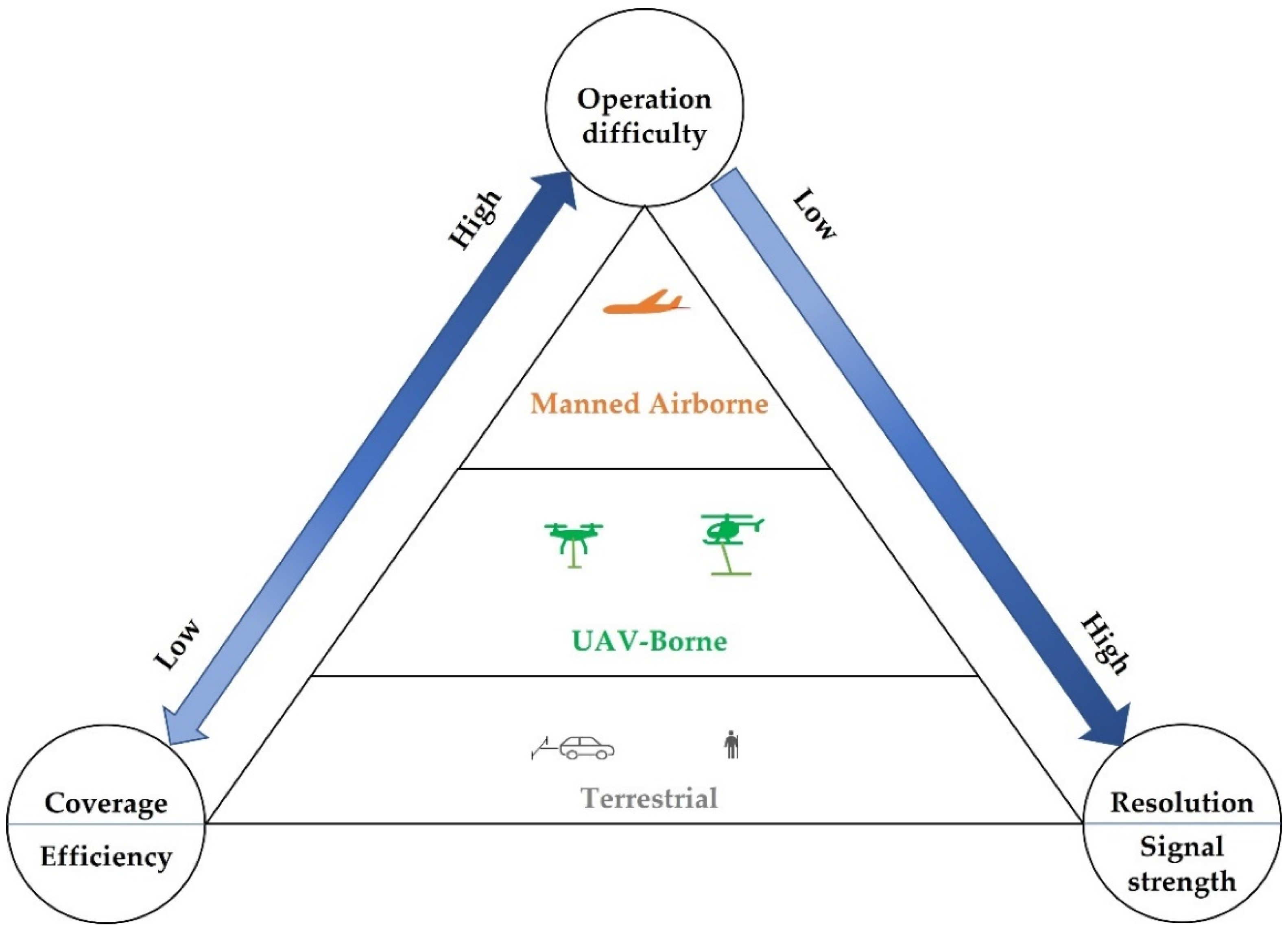
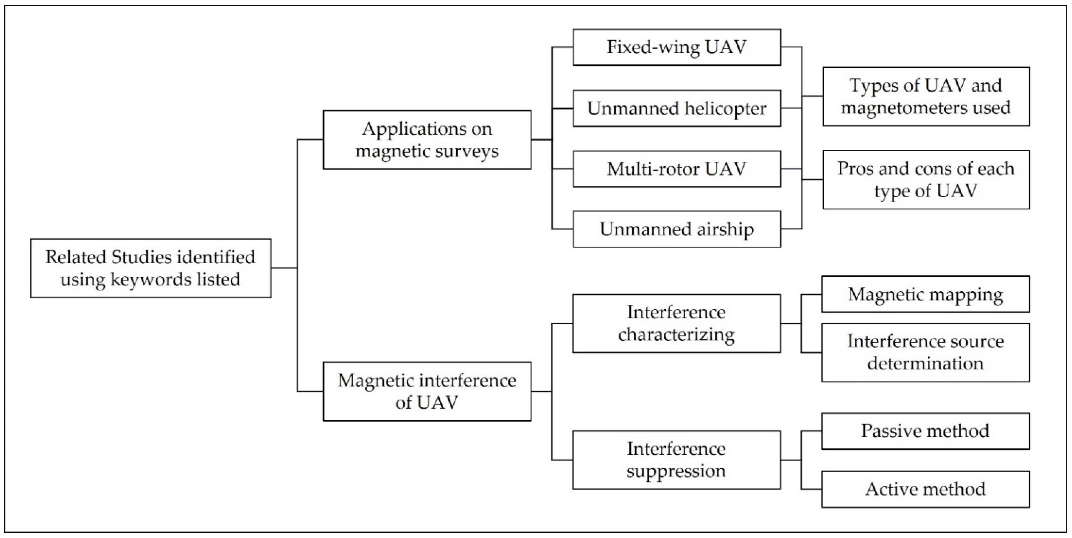
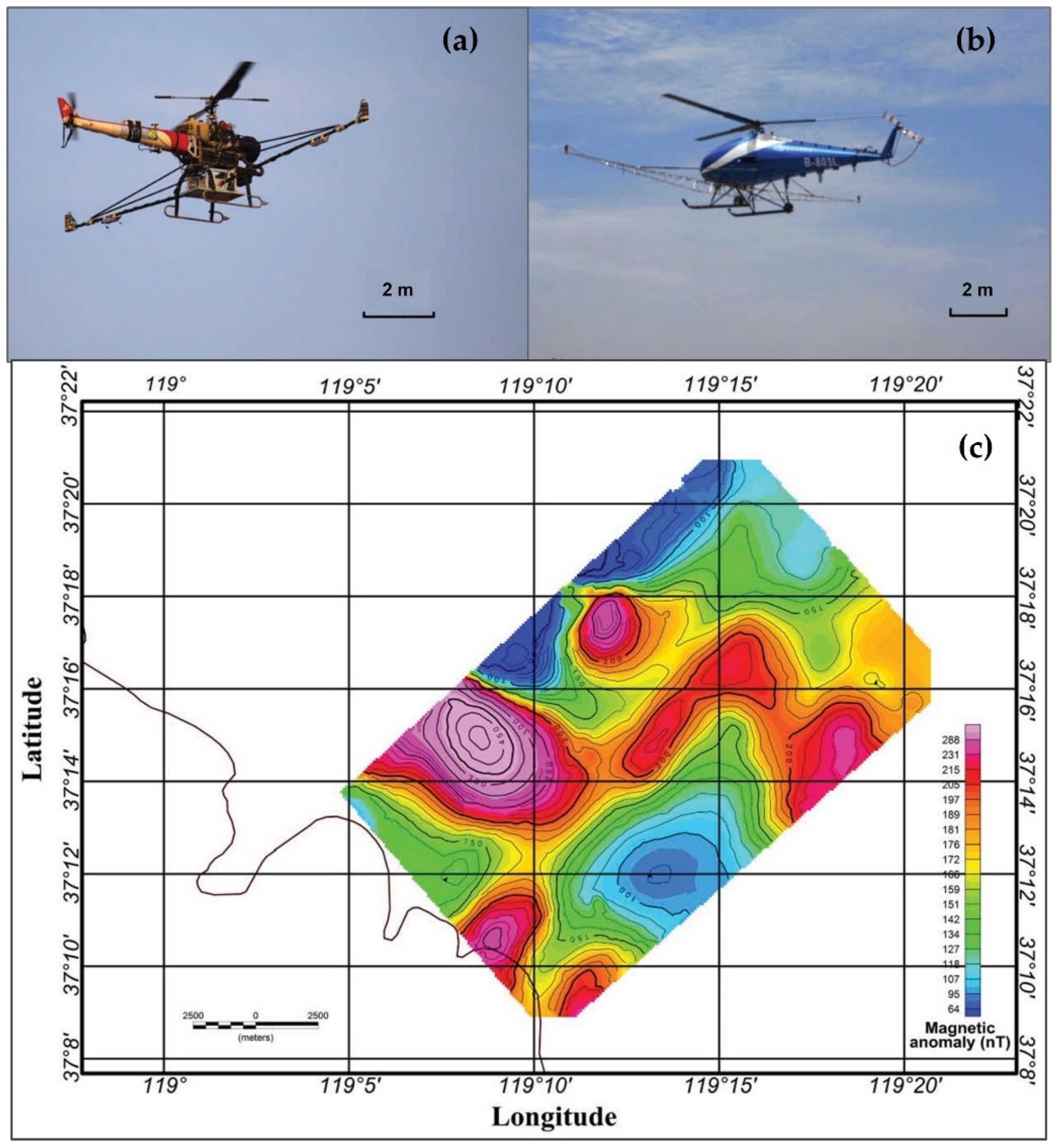
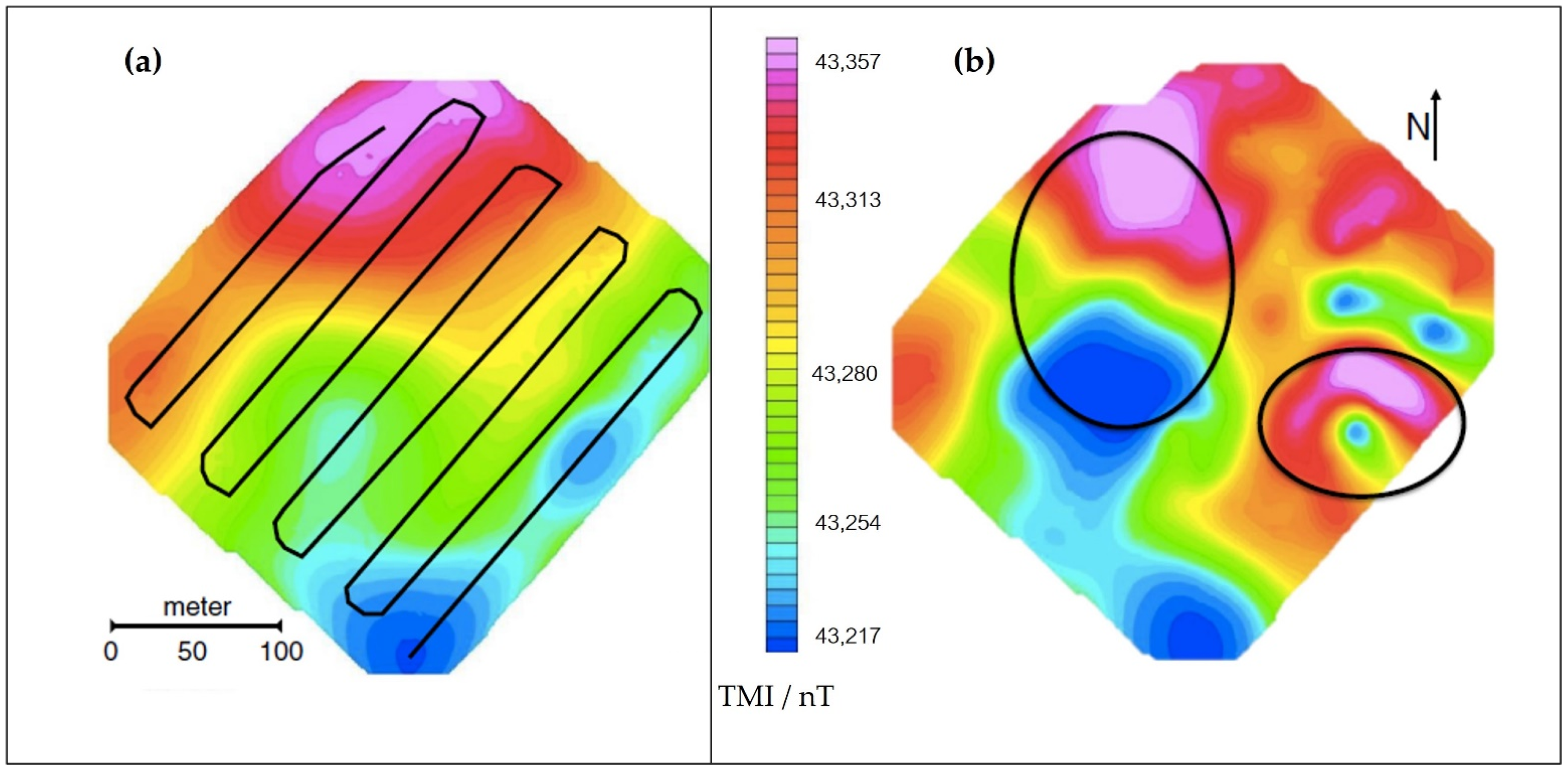
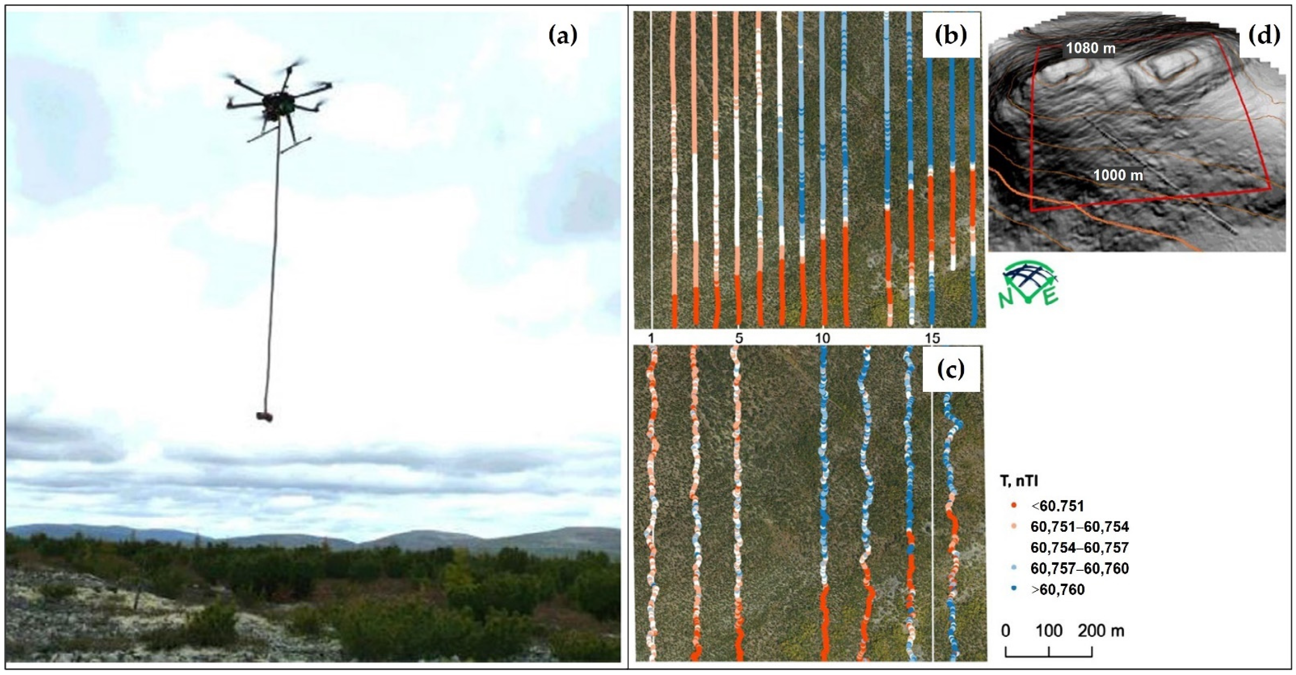
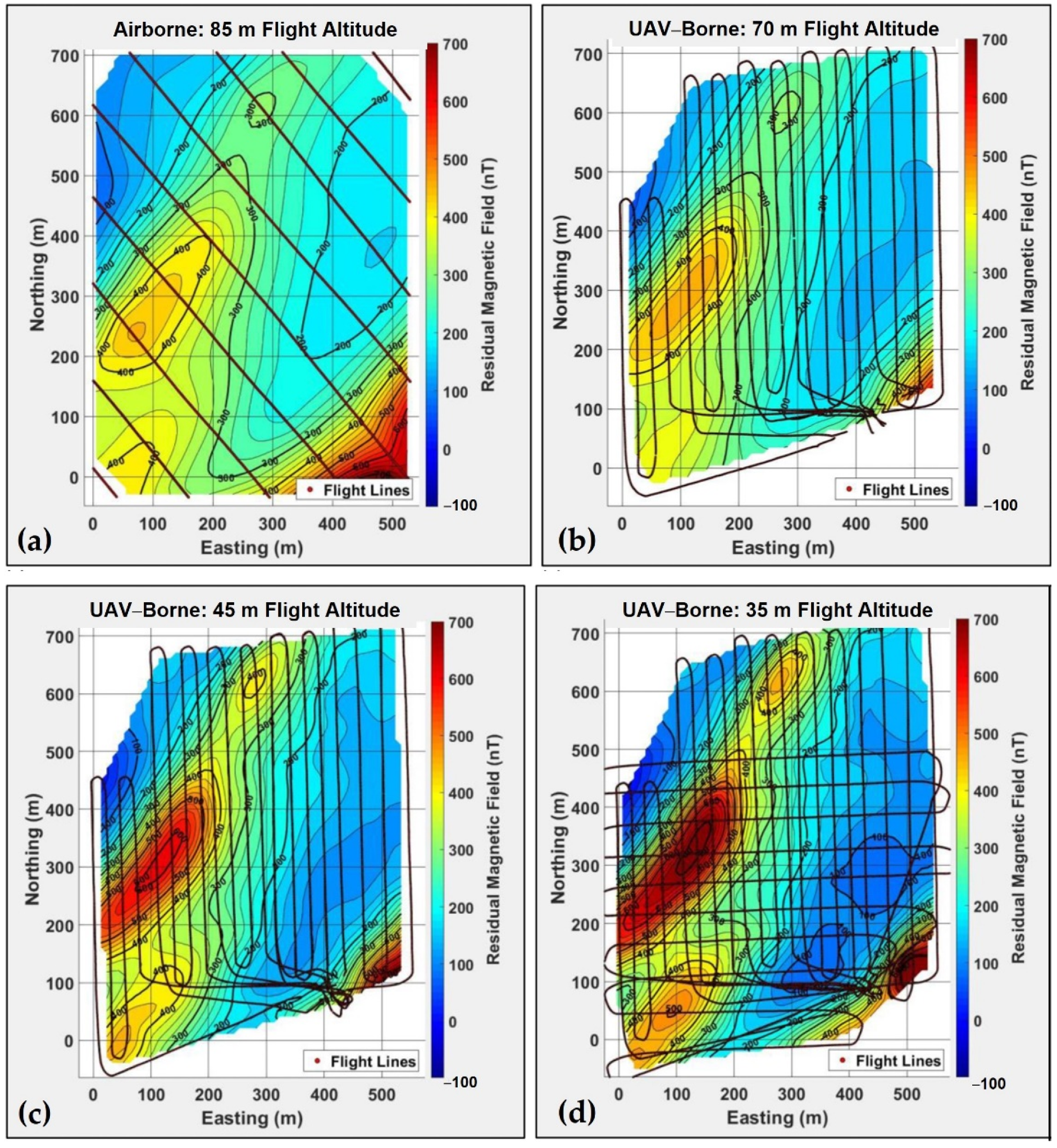
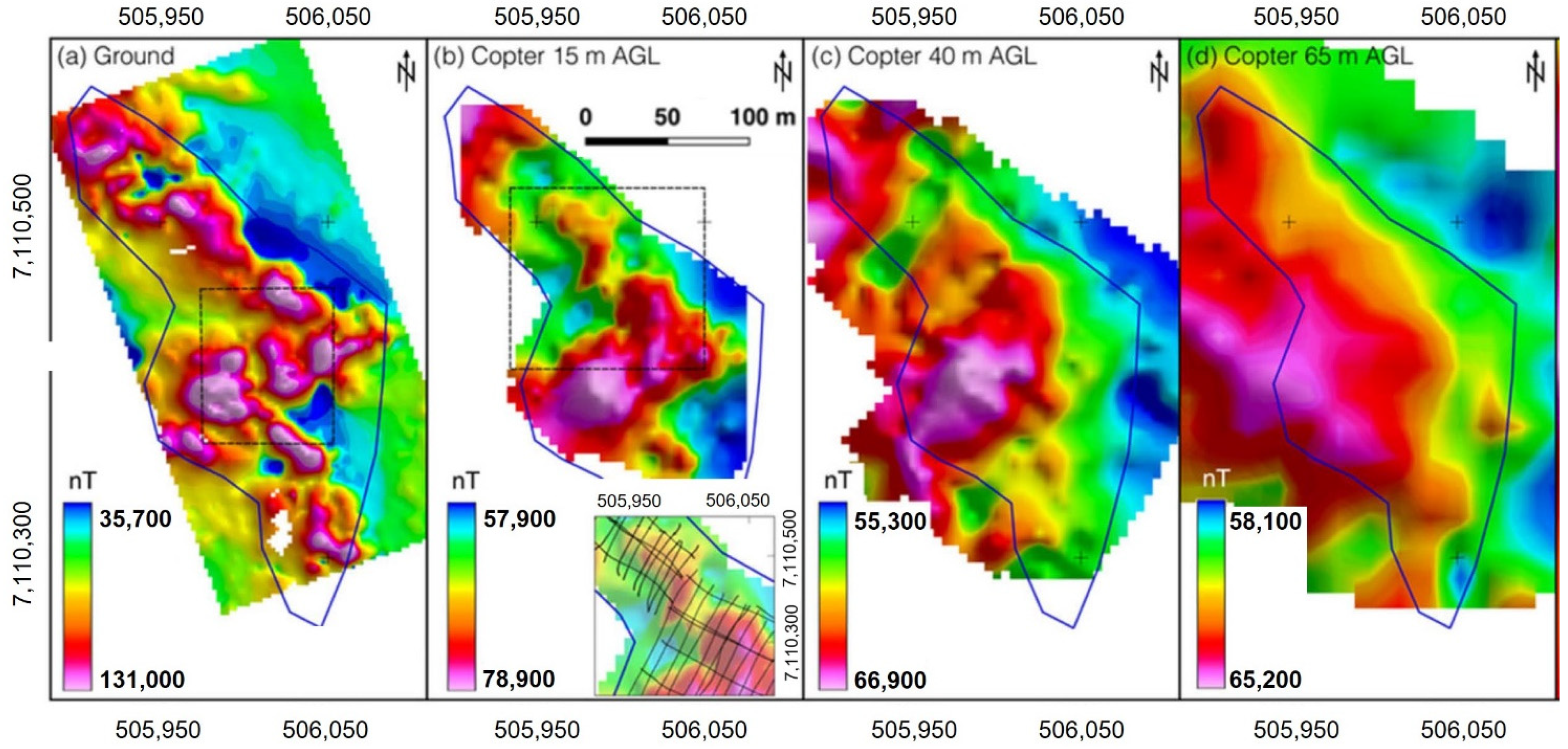
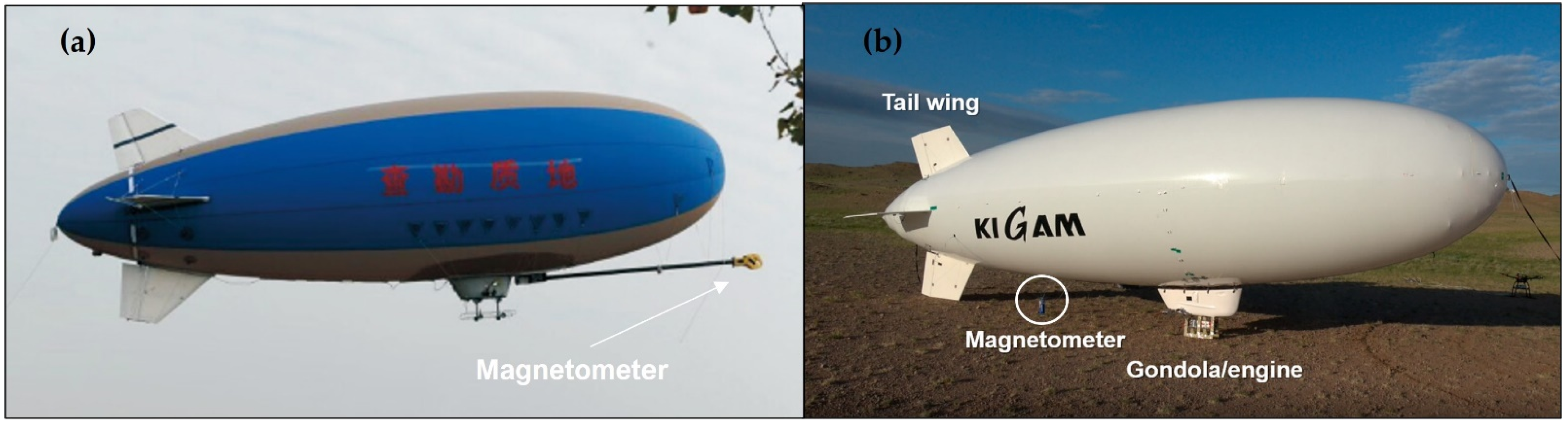
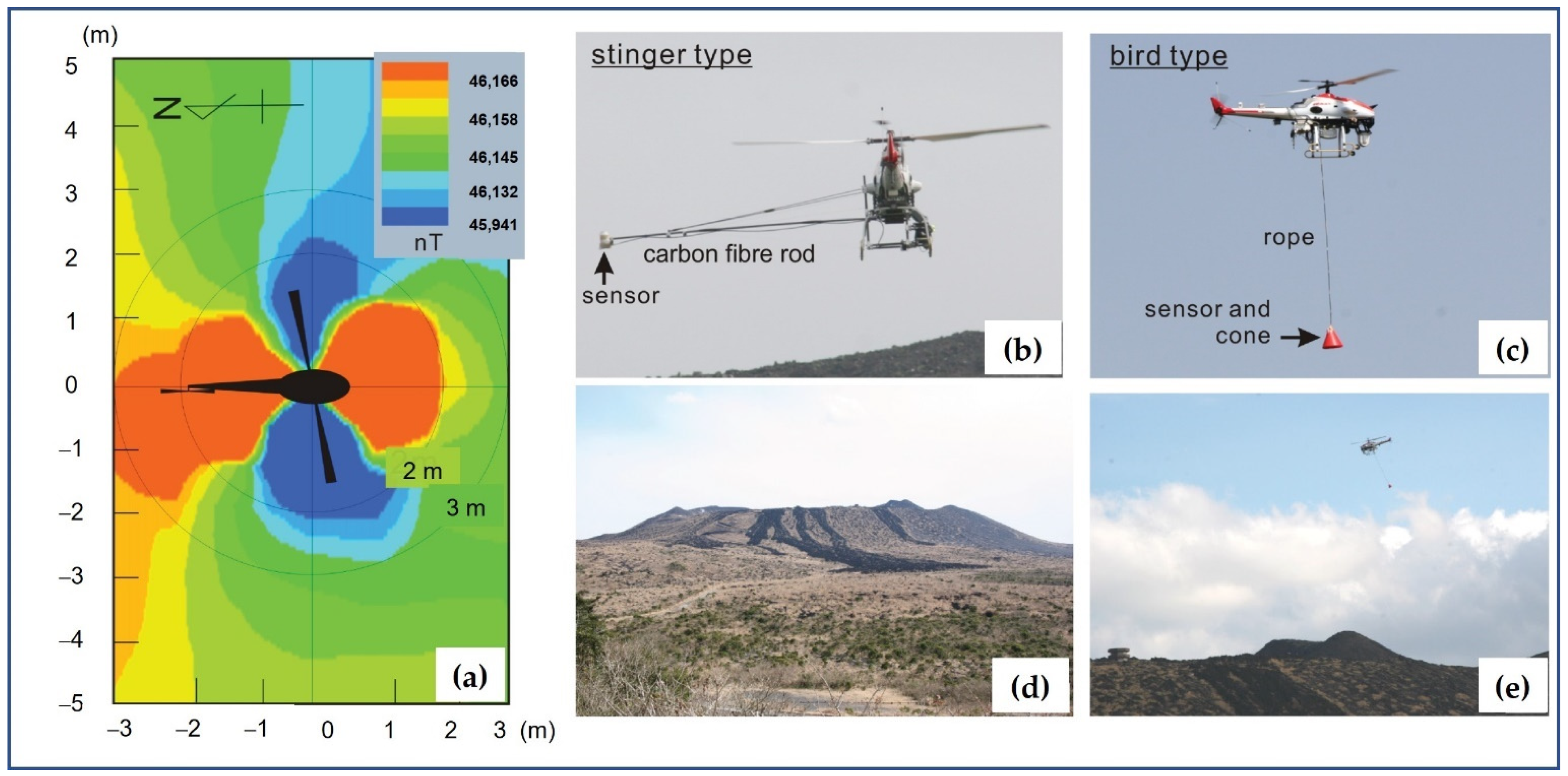
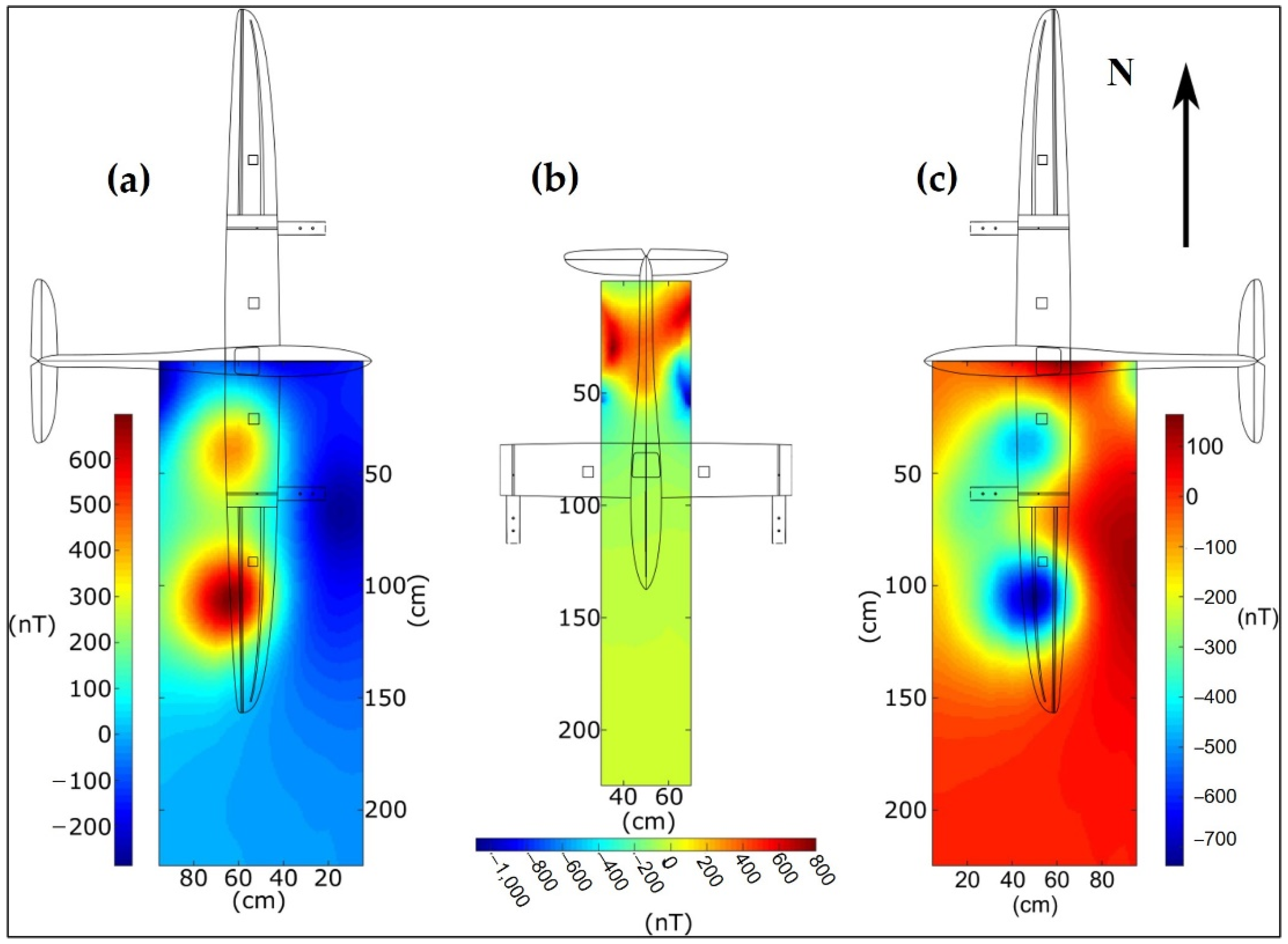
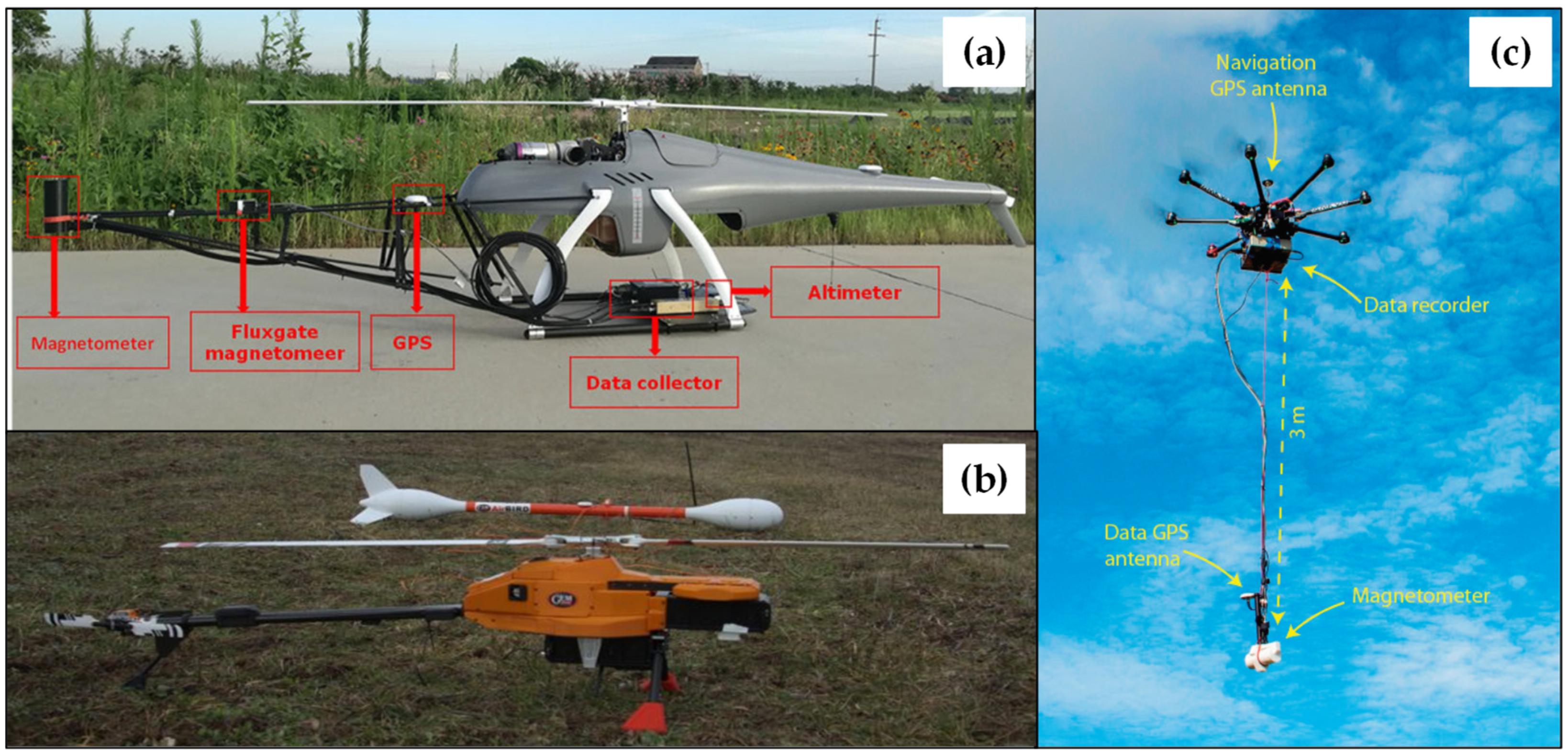
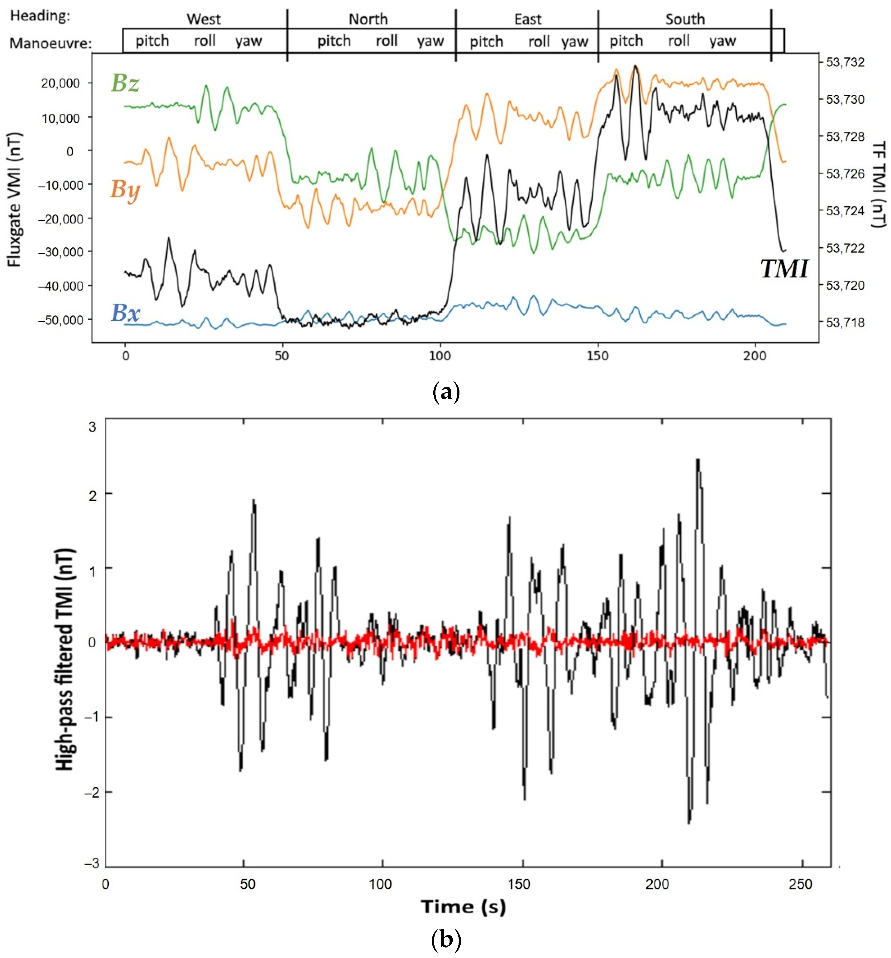
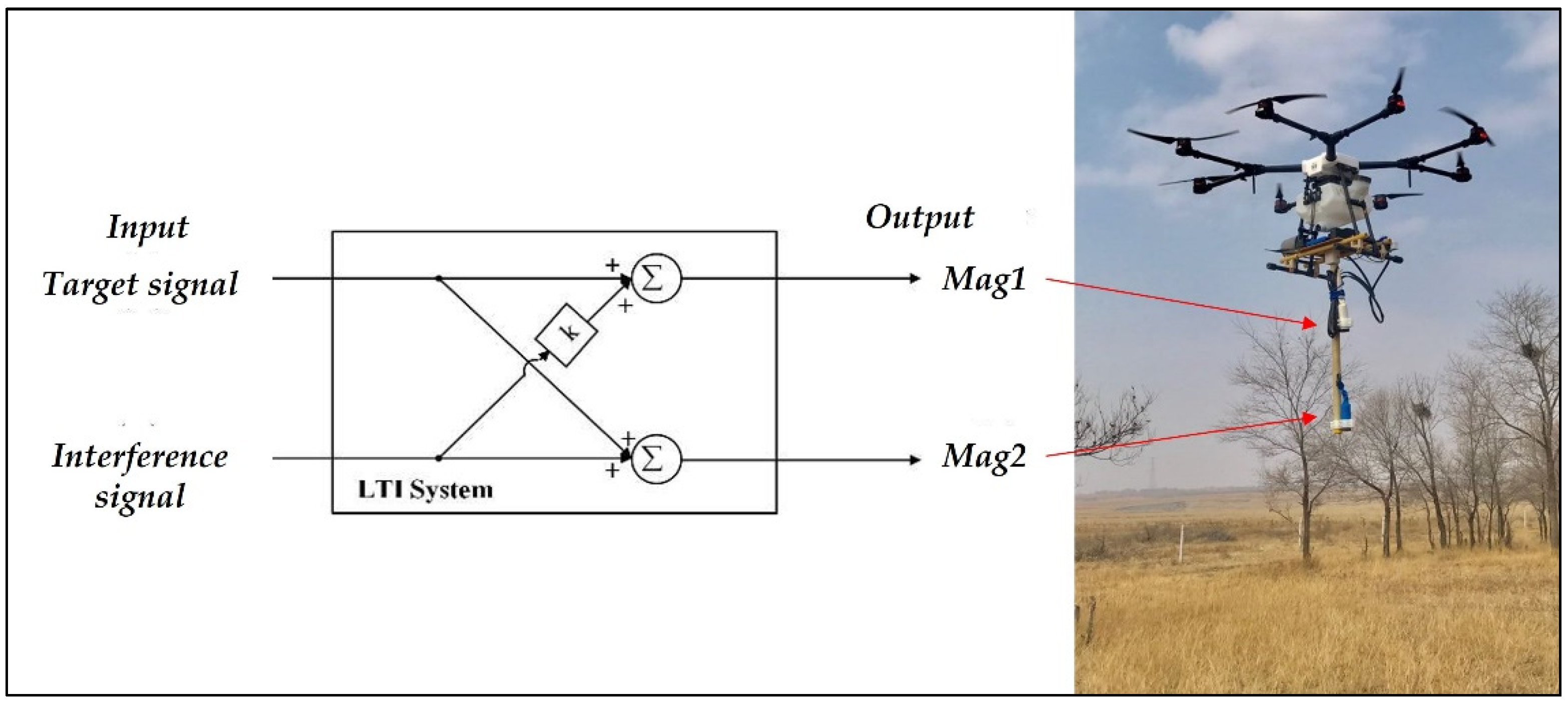
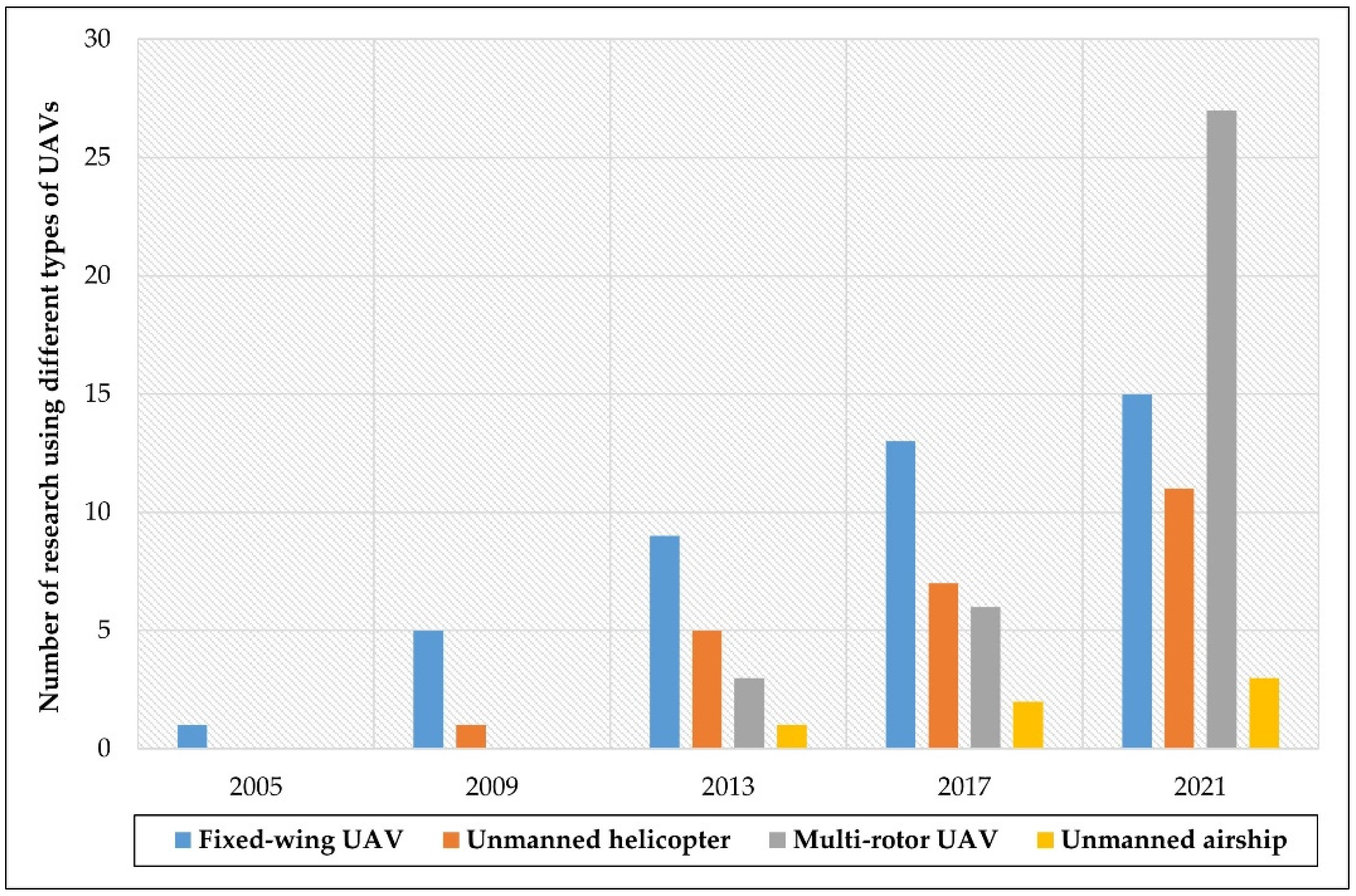
Table 1.
Summary of fixed-wing UAV applications for magnetic surveys.
| Reference | Year | UAV | Magnetic Sensors | Maximum Payload (kg) | Nominal Endurance (h) | Cruise Speed (km/h) | Aim of Study |
|---|---|---|---|---|---|---|---|
| Anderson and Pita [55] | 2005 | GeoRanger | A cesium vapor magnetometer | 5.4 | 15 | 75 | Offshore geophysical surveying |
| Gee et al. [56] | 2007 | GeoRanger | A cesium vapor magnetometer | 5.4 | 15 | 75 | Mapping geomagnetic field variations |
| Barnard [57] | 2008 | The Prion | A cesium vapor magnetometer | N 1 | N | 90 | Mineral exploration |
| Wells [58] | 2008 | GeoSurv II | Two cesium magnetometers and a fluxgate magnetometer | 9.1 | 8 | 111 | Aeromagnetic surveying |
| Forrester [59] | 2011 | ||||||
| Caron et al. [60] | 2013 | ||||||
| Funaki and Hirasawa [61] | 2008 | Ant-Plane 1,2 | A magneto-resistant magnetometer | 4 | 1.5 | 150 | Antarctic research |
| Ant-Plane 3-2,3 | 1 | 1.5 | 70 | ||||
| Ant-Plane 3-4 | 0.8 | 5 | 70 | ||||
| Ant-Plane 4-1,2 | 5 | 5 | 130 | ||||
| Ant-Plane 5 | 1 | 10 | 110 | ||||
| Funaki et al. [62] | 2014 | Ant-Plane 6-3 | A fluxgate magnetometer and a magneto-resistant magnetometer | 2 | 5 | 100 | Aeromagnetic surveys in Antarctic |
| Glen et al. [63] | 2013 | SIERRA | A cesium vapor magnetometer | 28.6 | 8 | 117 | Geophysical exploration |
| MGT [68] | 2013 | Single Mag | A fluxgate magnetometer | 5 | 0.5 | 90 | Geophysical exploration |
| Li et al. [64] | 2014 | CH-3 | A cesium vapor magnetometer | 145 | 10 | 180 | integrated geophysical survey |
| Wood et al. [65] | 2016 | Venturer | Two cesium vapor magnetometers | 8.28 | 10 | 120 | Aeromagnetic surveying |
| GEM Systems [69] | 2017 | The MONARCH | Two potassium magnetometers | N | 1.5 | 70 | Explore mineral potential, map UXOs and Archeology |
| Jackisch et al. [66] | 2020 | Albatros VT2 | A fluxgate magnetometer | N | 3 | N | Geological and geophysical mapping of outcrop |
| Ju et al. [67] | 2020 | CH-4 | A cesium magnetometer and a fluxgate magnetometer | 345 | 12 | 150 | Flight safety and data acquisition |
1 Not mentioned in the paper.
Table 2.
Summary of unmanned helicopter applications for magnetic surveys.
| Reference | Year | UAV | Magnetic Sensor | Maximum Payload (kg) | Nominal Endurance (h) | Maximum Speed (km/h) | Aim of Study |
|---|---|---|---|---|---|---|---|
| Versteeg et al. [70] | 2007 | RMAX | Geometrics G823A magnetometer | 31 | 1 | N 1 | Feasibility study |
| AutoCopter | 6.8 | 1 | |||||
| Bergen R/C | 4.5 | 0.5 | |||||
| RaptorCam | 0.9 | 0.3 | |||||
| McKay et al. [71] | 2011 | Maxi-Jocker | Geometrics G823A magnetometer | 4 | 0.25 | N | Subsurface ordnance detection |
| Mongoose | N | N | |||||
| Eck and Imbach [72] | 2012 | Scout B1-100 | A fluxgate magnetometer | 18 | 1.5 | N | Aeromagnetic surveying |
| Koyama et al. [40] | 2011 | RMAX-G1 | A cesium OPM | 10 | 1.5 | 72 | Volcano aeromagnetic survey |
| Hashimoto et al. [73] | 2014 | RMAX-G1 | A cesium OPM | 10 | 1.5 | 72 | Volcano aeromagnetic survey |
| Stoll [74] | 2013 | Scout B1-100 | A fluxgate magnetometer | 18 | 1.5 | N | Subsurface ordnance detection |
| Pei et al. [75] | 2017 | Z3 | A helium OPM and a fluxgate magnetometer | 25 | 1.5 | N | Magnetic survey of the beach–shallow sea transition area |
| V750 | 80 | 4 | N | ||||
| Zhang et al. [76] | 2019 | WH-110A | A cesium OPM and a fluxgate magnetometer | 35 | 3 | 60 | Geophysical exploration |
| Xi et al. [77] | 2019 | WH-110A | A cesium OPM and a fluxgate magnetometer | 35 | 3 | 60 | Geophysical exploration |
| Xu et al. [78] | 2020 | UFO-H | A cesium OPM and a fluxgate magnetometer | 35 | 3 | 43 | Geophysical exploration |
| Jiang et al. [79] | 2020 | SU-H2M | A potassium OPM and a fluxgate magnetometer | 45 | 2 | 60 | Mineral exploration |
1 Not mentioned in the paper.
Table 3.
Summary of multi-rotor UAV applications for magnetic surveys.
| Reference | Year | UAV | Magnetic Sensor | Endurance with Different Payload | Maximum Speed (km/h) | Aim of Study |
|---|---|---|---|---|---|---|
| Stoll [74] | 2013 | MD4-1000 | A fluxgate magnetometer | 1 h with a 1 kg load | N 1 | Near-surface ferrous objects detection |
| MGT [81,82] | 2013 | Single Mag | A fluxgate magnetometer | 20 min with a 1.3 kg load | 54 | Geophysical exploration, archeology |
| Dual Mag | 2 fluxgate magnetometers | UXO detection, pipeline detection | ||||
| Parvar et al. [83] | 2016 | Pioneer UAV-MAG | A potassium vapor magnetometer | 25 min with a 0.1 kg load | 50 | chromite detection |
| Macharet et al. [84] | 2016 | 3DR X8+ | A fluxgate magnetometer | 15 min with a 1 kg load | 90 2 | Aeromagnetic survey |
| Malehmir et al. [85] | 2017 | DJI S1000 | An Overhauser magnetometer | 20 min with a 2 kg load15 min with a 4 kg load | 64.8 | Mineral exploration |
| Cunningham et al. [86] | 2018 | The SkyLance | A cesium vapor magnetometer | 30 min with a 5 kg load | 37 | Mineral exploration |
| Parshin et al. [87] | 2018 | Heavyweight | A quantum Overhauser magnetometer | 20–30 min with a 15 kg load | 36 | Low-altitude geophysical magnetic prospecting |
| Li et al. [88] | 2018 | Six-rotor | A fluxgate magnetometer | 30 min with a 4 kg load | 43.2 | Aeromagnetic surveys |
| Cherkasov et al. [104] | 2018 | Geoscan 401 | A quantum magnetometer | 40 min with a 2.5 kg load | 50 | mineral exploration |
| Walter et al. [42] | 2019 | DJI S900 | A potassium vapor magnetometer | 5–7 min with a 2 kg load | 57.6 2 | Mineral exploration |
| Nikulin and de Smet [89] | 2019 | DJI Matrice 600 | A MFAM | 16 min with a 6 kg load 218 min with a 5.5 kg load 2 | 64.8 2 | Oil and gas wells locating |
| Schmidt et al. [41] | 2019 | DJI S1000+ | A cesium vapor magnetometer | 15 min with a 5 kg load 2 | 64.8 2 | Archeological survey |
| Jackisch et al. [99] | 2019 | Tholeg | A fluxgate magnetometer | 25 min with a 4.5 kg load | 40 | Mineral exploration |
| ISS Aerospace [103] | 2020 | UXO Magnetometer Array UAV | array of 7 magnetometers | N 1 | N 1 | UXO detection |
| Mu et al. [90] | 2020 | DJI MG-1P | 2 cesium OPMs | 20 min with a 4 kg load 29 min with a 14 kg load 2 | 43.2 2 | UXO detection |
| Luoma and Zhou [91] | 2020 | DJI Matrice 600 Pro | 2 fluxgate magnetometers | 16 min with a 6 kg load 218 min with a 5.5 kg load 2 | 65 2 | Geophysical exploration of subsurface features |
| Qiao et al. [92] | 2020 | MAG-DN20G4 | A fluxgate magnetometer | 25 min with a 7 kg load 2 | 28.8 | Mineral exploration |
| de Smet et al. [93] | 2020 | UMT Cicada | A MFAM | 1 h with a 2.5 kg load | N 1 | Oil and gas wells locating |
| Le Maire et al. [96] | 2020 | DJI M210 | A fluxgate magnetometer | 27 min without loadMaximum payload 2.3 kg | 61.2 | Aeromagnetic mapping of regional scale |
| Cunningham et al. [94] | 2021 | SkyLance 6200 | A cesium vapor magnetometer | 30 min with a 5 kg load | 37 | Gold exploration |
| Romero et al. [95] | 2021 | DJI Matrice 600 Pro | A vector magnetometer | 16 min with a 6 kg load18 min with a 5.5 kg load | 65 | Planetary Exploration |
| Gailler et al. [97] | 2021 | DJI Mavic 2 | A QTFM | 31 min with a 25 km/h speed | 72 | Volcano monitoring and geohazard assessment |
| Pisciotta et al. [98] | 2021 | DJI Phantom 4 | A fluxgate magnetometer | ~28 min | 72 | Archeological survey |
| Yoo Lee-Sun et al. [100] | 2021 | Eight-rotor | A fluxgate magnetometer | N 1 | N 1 | UXO detection |
| Shahsavani [101] | 2021 | FY680 | A magneto-inductive magnetometer | ~30 min | 46.8 | Mineral exploration |
| Kim et al. [102] | 2021 | DJI M210 | A scalar magnetometer | 27 min without load 2Maximum payload 2.3 kg 2 | 61.2 2 | Mineral exploration |
1 Not mentioned in the paper; 2 Not mentioned in the paper but can be found online or in other studies.
Table 4.
Summary of unmanned airship applications for magnetic surveys.
| Reference | Year | Magnetic Sensor | Maximum Payload (kg) | Nominal Endurance (h) | Cruising Speed (km/h) | Aim of Study |
|---|---|---|---|---|---|---|
| Petzke et al. [105] | 2013 | A fluxgate magnetometer | 3 | 1 | 18 | Anomalies detection |
| Wang et al. [106] | 2016 | A helium OPM and a fluxgate magnetometer | 13 | 2–4 | 46.8–75.6 | Mineral exploration |
| Kim et al. [107] | 2020 | A cesium OPM | 10 | 1 | N 1 | Magnetic exploration |
1 Not mentioned in the paper.
Table 5.
The distance and assembly mode between sensor and UAV in various studies.
| Reference | Year | UAV Type | Distance (m) | Magnetometer Assembly Mode |
|---|---|---|---|---|
| Kaneko et al. [108] | 2011 | Helicopter | 3 | Towed below the UAV with a long rope |
| Eck and Imbach [72] | 2012 | Helicopter | 4 | Rigidly fixed to the UAV frame by a rod |
| Hashimoto et al. [73] | 2014 | Helicopter | 4.5 | Towed below the UAV with a long rope |
| Jiang et al. [79] | 2020 | Helicopter | 2.4 | Rigidly located at the front of the UAV by a carbon fiber rod |
| Parvar et al. [83] | 2016 | Six-rotor | 3 | Suspended below the UAV with a cable |
| Macharet et al. [84] | 2016 | Eight-rotor | 1.1 | Rigidly mounted at the front of the UAV with an aluminum bar |
| Parshin et al. [114] | 2016 | Six-rotor | 3 | Suspended below the UAV with a cable |
| Malehmir et al. [85] | 2017 | Eight-rotor | 3 | Tied below the UAV with a cable |
| Cunningham et al. [86] | 2018 | Eight-rotor | 3.6 | Rigidly mounted at the front of the UAV |
| Cherkasov and Kapshtan [104] | 2018 | Quadrotor | 20 | Towed below the UAV with a long rope |
| Walter et al. [42] | 2019 | Six-rotor | 3 | Semi-rigid suspended below the UAV |
| Schmidt et al. [41] | 2019 | Eight-rotor | 3 | Attached to the UAV via long ropes |
| de Smet et al. [93] | 2020 | Six-rotor | 4 | Towed below the UAV with a long rope |
| Yoo Lee-Sun et al. [100] | 2021 | Eight-rotor | 1.2 | Towed below the landing pole with a cable |
| Shahsavani [101] | 2021 | Quadrotor | 3 | Towed below the UAV with two ropes |
| Kim et al. [102] | 2021 | Eight-rotor | 3 | Towed below the UAV with four ropes |
| Romero et al. [95] | 2021 | Six-rotor | 1.2 | Rigidly attached to the UAV with a rigid boom |
| Pisciotta et al. [98] | 2021 | Quadrotor | 4 | Suspended below the UAV with a long wire |
| Petzke et al. [105] | 2013 | Airship | ~4 | Towed below the UAV with a long boom |
| Wang et al. [106] | 2016 | Airship | 3.5 | Rigidly attached to the UAV frame with a carbon fiber rod |
Table 6.
The number of studies that used different types of magnetometers for each type of UAV.
| Magnetometers Used | Fixed-Wing UAV | Unmanned Helicopter | Multi-Rotor UAV | Unmanned Airship | Total |
|---|---|---|---|---|---|
| A scalar magnetometer | 6 | 4 | 13 | 1 | 24 |
| A vector magnetometer | 3 | 2 | 10 | 1 | 16 |
| Two or more scalar magnetometers | 2 | 0 | 2 | 0 | 4 |
| Two or more vector magnetometers | 0 | 0 | 2 | 0 | 2 |
| Both scalar and vector magnetometers | 4 | 5 | 0 | 1 | 10 |
Table 7.
The various magnetometers used in different applications and their specifications.
| Reference | Magnetometers Used | Resolution (nT) | Sensitivity (nT rms/√Hz) | Heading Error (nT) | Aim of Study |
|---|---|---|---|---|---|
| Funaki et al. [62] | A fluxgate magnetometer | 0.1 | - 1 | - | Aeromagnetic survey |
| A magneto-resistant magnetometer | 7 | - | - | ||
| Wood et al. [65] | Two cesium magnetometers | - | <0.004 | ±0.15 | |
| Koyama et al. [40] | A cesium OPM | - | <0.008 | <1.5 | |
| Macharet et al. [84] | A fluxgate magnetometer | <0.5 | - | - | |
| Parshin et al. [87] | A quantum Overhauser magnetometer | 0.001 | - | - | |
| Pei et al. [75] | A helium OPM | 0.001 | - | - | |
| A fluxgate magnetometer | 1 | - | - | ||
| Jackisch et al. [99] | A fluxgate magnetometer | 0.5 | - | - | Geophysical/Mineral exploration |
| Jiang et al. [79] | A potassium OPM | 0.0001 | - | ±0.05 | |
| A fluxgate magnetometer | - | 0.02 | - | ||
| Parvar et al. [83] | A potassium OPM | 0.0001 | 0.0025 | ±0.05 | |
| Malehmir et al. [85] | An Overhauser magnetometer | 0.01 | 0.022 | ±0.1 | |
| Cherkasov et al. [104] | A quantum magnetometer | - | 0.01 | - | |
| Shahsavani [101] | A magneto-inductive magnetometer | 2.7 | 0.004 | - | |
| Nikulin and de Smet [89] | A MFAM | - | 0.001 | - | Subsurface objects/UXO detection |
| Mu et al. [90] | Two OPMs | - | 0.003 | ±0.3 | |
| Yoo Lee-Sun et al. [100] | A fluxgate magnetometer | 0.1 | - | - | |
| Schmidt et al. [41] | A cesium vapor magnetometer | - | 0.005 | - | Archeological survey |
| Romero et al. [95] | A vector magnetometer | 1 | 0.02 | - | Planetary exploration |
| Gailler et al. [97] | A QTFM | - | 0.001 | <3 | Geohazard assessment |
1 Not mentioned in the paper.
Publisher’s Note: MDPI stays neutral with regard to jurisdictional claims in published maps and institutional affiliations. |
© 2021 by the authors. Licensee MDPI, Basel, Switzerland. This article is an open access article distributed under the terms and conditions of the Creative Commons Attribution (CC BY) license (https://creativecommons.org/licenses/by/4.0/).
Share and Cite
MDPI and ACS Style
Zheng, Y.; Li, S.; Xing, K.; Zhang, X. Unmanned Aerial Vehicles for Magnetic Surveys: A Review on Platform Selection and Interference Suppression. Drones 2021, 5, 93. https://doi.org/10.3390/drones5030093
AMA Style
Zheng Y, Li S, Xing K, Zhang X. Unmanned Aerial Vehicles for Magnetic Surveys: A Review on Platform Selection and Interference Suppression. Drones. 2021; 5(3):93. https://doi.org/10.3390/drones5030093
Chicago/Turabian StyleZheng, Yaoxin, Shiyan Li, Kang Xing, and Xiaojuan Zhang. 2021. "Unmanned Aerial Vehicles for Magnetic Surveys: A Review on Platform Selection and Interference Suppression" Drones 5, no. 3: 93. https://doi.org/10.3390/drones5030093