
The Effectiveness of the DIC as a Measurement System in SRG Shear Strengthened Reinforced Concrete Beams


1
ISISE, Department of Civil Engineering, University of Minho, 4800-058 Guimarães, Portugal
2
Department of Civil Engineering, University of Calabria, 87036 Rende, Italy
*
Author to whom correspondence should be addressed.
Crystals 2021, 11(3), 265; https://doi.org/10.3390/cryst11030265
Submission received: 10 February 2021
/
Revised: 24 February 2021
/
Accepted: 1 March 2021
/
Published: 8 March 2021
(This article belongs to the Special Issue Composite Systems for Structural Strengthening)
Abstract
:Steel Reinforced Grout (SRG) materials are generating considerable interest as strengthening system of reinforced concrete (RC) structures. They are finding increasing use in several civil engineering applications mainly due to the advantages they offer over traditional material such as high strength to weight ratio, ease of application, durability and low price. This paper describes the results of an experimental investigation carried out on SRG shear strengthened RC beams and gives evidence of the Digital Image Correlation (DIC) effectiveness as a measurement system. The tests performed had two main objectives: (i) assess the effectiveness of continuous and discontinuous U-wrapped jackets comprising a different number of layers and strips; (ii) assess the shear crack distribution during the tests by means of the DIC measurements. The results confirmed that reinforcing RC beams with SRG jackets can increase the load-bearing capacity; when the beam was reinforced with a continuous two-layered SRG strip, an increase of 84% was observed (compared to the unreinforced beam). The Linear Variable Differential Transformers (LVDT) measurements validated the results obtained by means of the DIC.
1. Introduction
Composite materials are well used in several engineering applications, ranging from marine to civil [1,2,3,4]. The fibre reinforced polymer (FRP) system is among the most widely used composite material in civil engineering applications due to its high mechanical performance, improved durability, and lightness [5,6]. Despite these advantages, legitimate concerns are related to their behaviour when exposed to elevated temperature or fire; due to their organic matrix, the material decomposes, releasing heat and toxic gases when heated at around 300–500 °C. However, the mechanical properties’ degradation occurs at an even lower temperature than the range mentioned above, especially when the matrix’s glass transition temperature is approached (between 65 and 150 °C).
Thus, Fiber Reinforced Cementitious Matrix (FRCM) system is finding increasing use as a strengthening system of RC structures. FRCM composites consist of different types of fibres (namely Aramide, Basalt [7], Carbon [8], Glass [9] and polyparaphenylenebenzobisthiszole (PBO) [10]) covered with inorganic matrices (cement-based or lime-based). In this context, steel fibres represent a low-cost alternative to the fibres mentioned above. The steel sheets are mono-directional and glued to glass fibres in order to control the distance between the single yarns; the following types of steel are usually employed in the SRG system: (i) ultra-high-strength steel wire and (ii) stainless steel [11,12]. SRG systems’ effectiveness was studied on concrete [13,14] and masonry structures [15]. In all these studies, a considerable improvement in terms of load-bearing capacity was observed. Thermou et al. [16] performed shear tests on SRG reinforced concrete beams; from the results obtained, they assessed that SRGs effectively improve the shear capacity and the ductility of RC beams. For the beams strengthened with SRG U-wraps, a drastic improvement was observed; the ultimate load was 104% higher than that observed on the un-strengthened beam. Wakjira and Ubead [14] conducted an experimental and analytical investigation about reinforced concrete T-beams strengthened with SRG wraps. The results confirmed that the shear response of the beam is significantly improved using SRG jackets, presenting the ultimate load increase ranging from 10% to 71% (compared to the un-strengthened beam).
In the field of RC beams reinforced with FRCM and SRG system, a challenging area is monitoring the strain evolution on the strengthened area. In this framework, Digital Image Correlation (DIC) technique is spreading a great interest in the research community because of its low costs, effectiveness and capacity to monitoring the displacements and strains during experimental tests [17,18,19].
Pohoryles et al. [20] presented a comparative analysis of instrumentation for monitoring beams retrofitted with FRP and FRCM systems. They demonstrated DIC measurements’ accuracy by comparing the strains and the displacements with what was found by traditional measurements methods such as strain gauges and LVDTs.
Marcinczak and Trapko [21] investigated a set of RC beams strengthened in shear with PBO-FRCM composite materials. The measurement of the deformations of the composites was carried out using both strain gauges and the optical DIC. Through the use of the latter method, the authors were able to analyse the entire composite behaviour, contrary to what was observed with the strain gauges, which only allow the analysis of a specific and limited area.
Similarly, Yang et al. [22] carried out several tests on RC beams strengthened with an FRCM system made of fibre grid reinforced with engineered cementitious composite (ECC) matrix. The authors monitored all the tested beams’ crack patterns using DIC technique. The tests have shown that the interfacial debonding of the shear strengthening layer and separation of the concrete side covers are the two typical failure modes observed in the beams strengthened with the cast-in-place method and the prefabricated method, respectively.
The literature analysis shows that the DIC is extensively adopted to monitor the strain evolution of FRCM systems, whereas, concerning the SRG system, the opportunities, risks, and potential of the DIC techniques are not fully understood, making this topic worthy of investigating.
This work aims to assess the DIC’s effectiveness as a measurement system in SRG shear strengthened reinforced concrete beams. The work is organised as follows. Section 2 describes the experimental setup and its integration with the DIC monitoring system. Section 3 presents the experimental program. Section 4 illustrates the results regarding loading displacement curves, failure modes, and damage evolution detected by the DIC system. Remarkable conclusions are reported in Section 5.
2. Experimental Setup and Integration of the DIC Technique
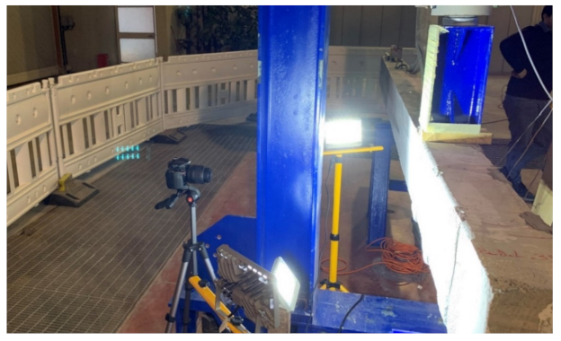
The tested sample consists of strengthened RC beams subjected to a non-symmetric three-points bending test (simply supported beam with one-point load) under quasi-static load (see Figure 1). The specimens were subjected to a monotonic load until failure at a loading rate of 40 N/s. Concerning the beam’s deflections, these were evaluated by means of four LVDTs installed along the entire length of the beam; two LVDTs were mounted in correspondence of the supports, while the remaining ones were installed at the loading point (one for each side of the beam). The test setup was integrated through a high-res digital camera (Nikon D5200, Nikon corp., Tokyo, Japan) and two high frequency LED lights (used to provide the necessary image contrast) for the DIC purpose.
DIC is a non-contact full-field strain measurement technique. DIC’s basic concept is to compare two images of a sample before, during and after the loads’ applications. Displacements are detected by correlating the pixel subsets of blocks’ position in the original and deformed image, normally based upon contrast (i.e., grey intensity levels) [23]. Hence, the Area of Interest (AoI) was painted with a speckle pattern using a special brush and black ink. The digital camera was positioned on a tripod at a distance of 100 cm to the beam focusing the AoI; pictures were taken for each load step that defines the tests’ loading history. The picture resolution was equal to 4496 × 3000 pixels, whereas the DIC parameters adopted for the computation were assumed as follows:
- Subset options: (i) subset radius = 60; (ii) subset spacing = 2.
- Iterative solver options: (i) diff norm = 10−6; (ii) iterations number = 50.
- Multithreading options: (i) number of threads = 1.
The freeware Matlab script Ncorr (Georgia Institute of Technology, Georgia, USA), developed by Blaber et al. [23], was employed to process the acquired images. This technique has been adopted to obtain the strain contours at several load level. Furthermore, because the range of acquisition is synchronised to the load cell as well as the LVDTs, an additional measure of the load-displacement curves has been retrieved from the correlation of the digital images collected. Figure 2 shows a representation of the installed DIC system.
3. Experimental Program
The experimental programme consisted of four RC beams strengthened with the SRG system, which were tested using a non-symmetric three-point bending configuration. The specimens involved are part of an extensive experimental campaign reported in [24,25]. As listed in Table 1, the RC beams campaign had the following characteristics (nomenclature in brackets): (i) beam strengthened with a continuous two-layered SRG strip (B-C-2L); (ii) beam strengthened with 4 discontinuous two-layered SRG strips (B-D-2L-4S); (iii) beam with a similar configuration to the B-D-2L-4S, but with only three strips (B-D-2L-3S); (iv) beam with a similar configuration to the B-D-2L-3S, but with only 1 layer (B-D-1L-3S).
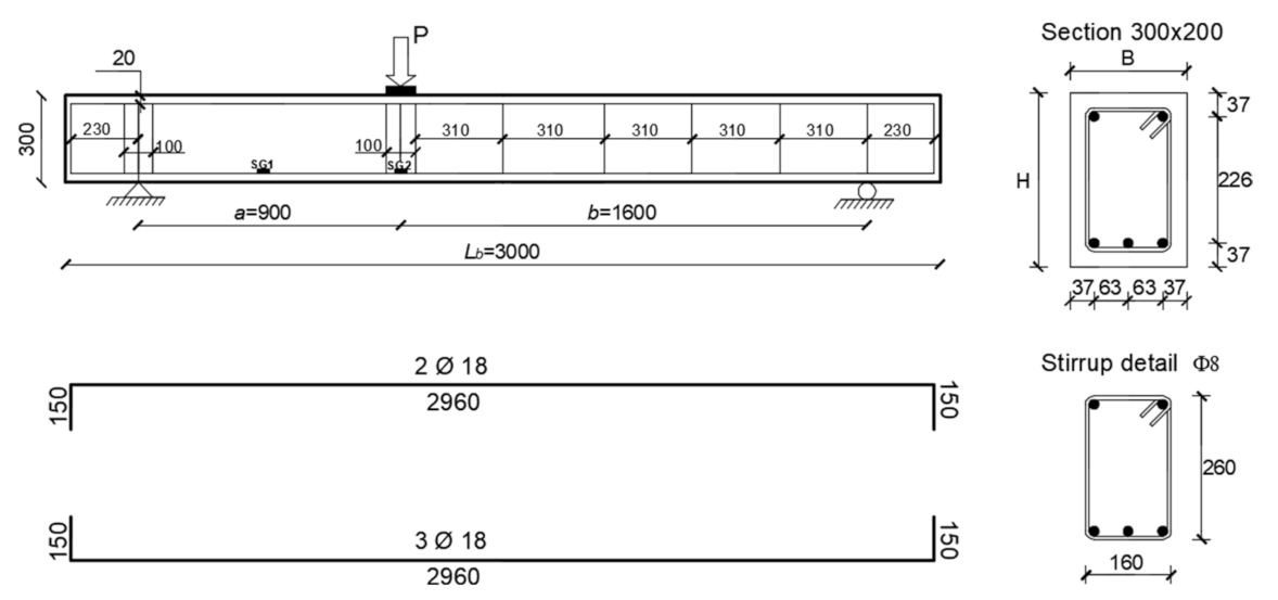
Table 1 reports distance from centre to centre between two consecutive strips sf and the width of the strips wf. All the beams were characterised by a rectangular cross-section (200 mm × 300 mm) and a length of 3000 mm. The RC beams were internally reinforced using three steel rebars with a nominal diameter of 18 mm in the longitudinal direction placed on the top (compression) and bottom (tension) sides. In order to assess the effects of the SRG system on the shear response of the beam, all the specimens were designed without transverse reinforcement in the shorter shear span (800 mm length), where the SRG system was applied (see Figure 3). In fact, the transverse reinforcement’s presence would contribute to the beam assembly’s shear response, thus not allowing a straightforward evaluation of the SRG system effectiveness. For this purpose, only the remaining part of the beam (shear span of 1600 mm length) was equipped with transverse reinforcement; the steel stirrups used had a nominal diameter of 8 mm (concrete cover of 20 mm).
Specimen Preparation and Material Properties
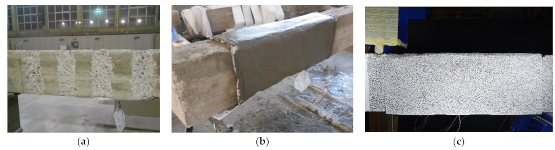
The beams tested in this study were cast in plywood formworks using a ready-mixed concrete, employing a Portland cement type 1 and aggregates with a maximum size of 25 mm. Three days after the casting, they were demolded and stored in the laboratory facilities (covered with a wet burlap). At first, the concrete surface was roughened using a sandblasting (see Figure 4a), in order to provide better bonding performances—the roughness profile adopted was about 5 mm (defined according to the recommendation of the manufacturer [26]). Before applying the external reinforcement, the fibres were cut and modelled (bent), creating an u-wrap during the casting. Once the steps mentioned above were completed, the preparation of the SRG system started, consisting of three main phases: (i) the cement-based matrix was applied on the treated concrete surface (internal layer); (ii) the steel fibres were slightly pushed inside the internal matrix layer; (iii) the matrix were applied on the fibres (external layer); see Figure 4b. The cement-based matrix thickness adopted was approximately 3 mm.
It is worth mentioning that for beams strengthened with two layers, the steps mentioned above must be repeated. After 28 days, the critical shear region of the beams (from now on referred to as “area of interest” (AoI)) was painted with a speckle pattern using a special brush and black ink; this pattern represents the ideal reference system for the DIC purpose (see Figure 4c).
Regarding the concrete, the compressive and tensile strength were equal to 14.4 MPa (C.o.V. of 0.01) and 2.42 MPa (C.o.V. of 0.02), respectively. Concerning the steel rebars, the following properties were obtained from the tensile tests performed: tensile strength of 617 MPa (C.o.V.of 0.01) and yielding strength of 564 MPa (C.o.V of 0.02) for the longitudinal reinforcement; and tensile strength of 565 MPa (C.o.V. of 0.02) and yielding strength of 644 MPa (C.o.V of 0.01) for the transversal reinforcement. The mechanical characterisation of the SRG system comprised the following experimental tests: (i) compressive and flexural tensile tests on cement-based matrix; (ii) tensile tests on dry steel fibres and (iii) tensile tests on SRG specimens. The tensile strength and the compressive strength on the cement-based matrix were determined according to [27] and they were equal to 10.90 MPa (C.o.V of 0.07) and 55.54 (C.o.V of 0.02), respectively. The tensile properties of the steel fibres were determined in accordance to [28]. The tests were conducted under displacement control at a speed of 0.5 mm/s. The elastic modulus of the steel fibres, tensile strength and ultimate strain, were equal to 197 GPa (C.o.V. of 0.06), 3.07 GPa (C.o.V. of 0.014) and 1.9% (C.o.V. of 0.08), respectively. Finally, the tensile properties of the SRG system were assessed according to [28]. The tests were conducted under displacement control at a speed of 0.2 mm/s. The axil strain, tensile stress and tensile modulus for the SRG specimen were equal to 20.8 % (C.o.V. of 0.07), 2.77 GPa (C.o.V. of 0.03) and 154 GPa (C.o.V. of 0.08), respectively, and the values are referred at the third phase [11,12,29,30,31].
4. Results
4.1. Load Displacement Curve
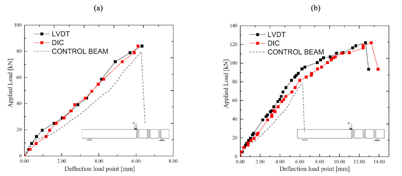
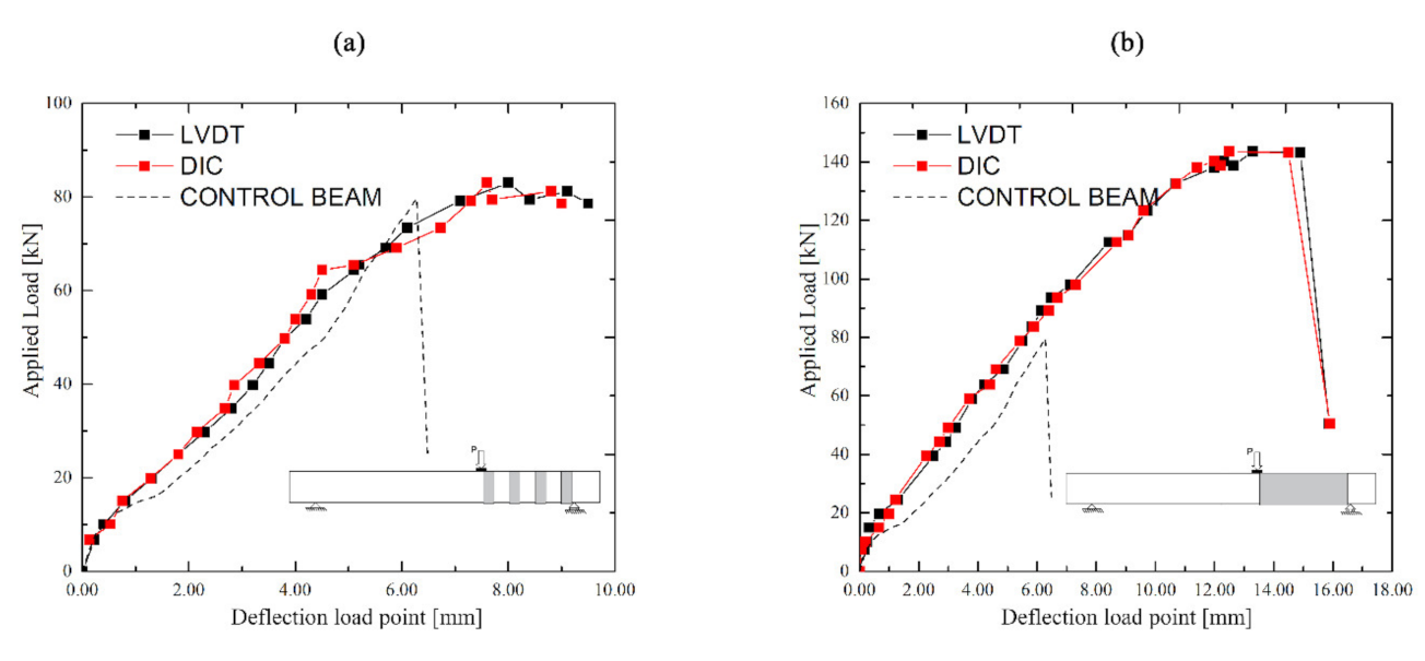
Figure 5 and Figure 6 show the load-deflection curves of the four tested beams. The black curves refer to the average displacement detected by using al LVDTs (placed at the loading point). In the same graphs, the red curves represent the response detected using DIC system. A picture at each load level was taken in order to monitor the front surface of AoI during the testing phases. The load curves obtained by using LVDT and DIC system were in good agreement. The performance between the two systems (LVDTs and DIC), are compared and the values of the deflection at the maximum load level are summarised in Table 2. Pu indicates the failure load, while δu indicates the corresponding deflection values (meaning the average of the two LVTDs at the load point).
4.2. Failure Mode
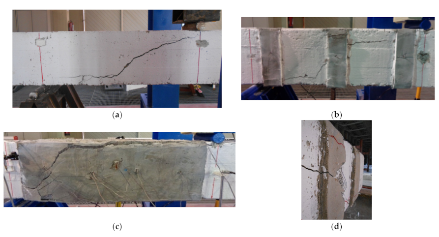
The un-strengthened beam and the strengthened beams failed in shear after the formation of a main diagonal crack in the shear zone (see Figure 7a). Concerning the reinforced beams, the main shear crack was clearly visible on the SRG jacket due to the mortar’s brittle response, which also reported a significant crack. Finally, the failure observed was due to the interlaminar failure that occurred inside the SRG U-wraps (Figure 7c).
4.3. Evaluation of Damage Based on Digital Image Correlation
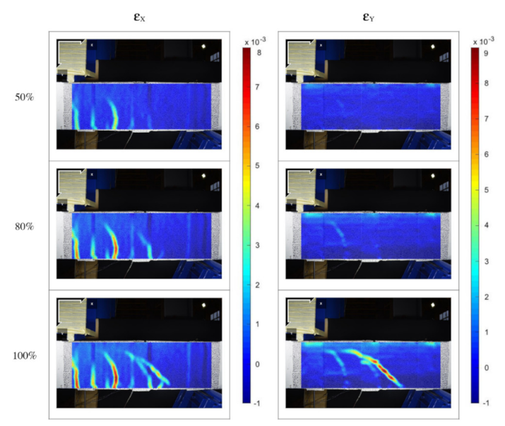
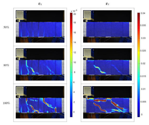
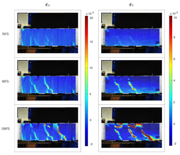
The DIC system was also employed to monitor the displacement field and consequently compute the strain contours developed during the loading process. This technique was employed to evaluate the local strains in the AoI of the beams, which present the following dimensions: 1 m long and the height is equal to the beam’s height. Three different loading stages were finally considered, namely 50%, 80% and 100% of the peak load. Figure 8, Figure 9, Figure 10 and Figure 11 show the evolution of the strain contour on the AoI surface, which describes the damage distribution during the loading stage.
In particular, Figure 8, Figure 9, Figure 10 and Figure 11 show the colour maps of the beams B-D-1L-3S, B-D-2L-3S, B-D-2L-4S and B-C-2L, respectively.
Figure 8 shows the colour maps of the U-Wrapped beam with a single layer (B-D-1L-3). In this case, the flexural crack starts at the lower edge of the beam. As the load increases, flexural cracks develop in the area between the U-Wrap strips. Concerning the vertical deformations, the larger values of strains were concentered along the shear crack that joins the point of applying force with the support. It is worth mentioning how the reinforced regions (SRG strips) showed the lower deformations values, while the higher values were detected on the un-reinforced concrete surface and at the interfaces with the strengthening system.
The strain colour maps of the U-Wrapped beam with two layers (B-D-2L-3S) is represented in Figure 9. In this case, both the horizontal and the vertical strains start at the interface reinforcement concrete beam support region, whereas the area strengthened with SRG strips showed the lower value of strains, demonstrating the ability of the adopted reinforcement to increase the stiffness as well as the strength of the beam. As the beam previously described, the reinforced regions were affected by lower deformations than the un-reinforced strips and the SRG system-concrete interfaces.
The strain colour maps of the U-Wrapped beam with two layers (B-D-2L-4S) is represented in Figure 10. The DIC confirmed how the strips regions’ strains were strongly reduced compared to those detected on the un-reinforced concrete surface. Concerning the vertical deformations corresponding to the peak load, the shear cracks were observed only on the concrete surface, whereas the SRG strips were not involved in the crack propagation, as shown in the other tested beams.
Figure 11 shows the strain maps of the U-Wrapped beam with a single strip and two layers. In this case, the FRCM surface showed a damage pattern more homogeneous than the previous ones. At the peak load, the vertical strains were well visible, following the shear deformation that occurs on the concrete support below the FRCM system.
5. Conclusions
This paper described an experimental investigation to asses RC beams’ shear behaviour strengthened with different U-wrap SRG jackets. The experimental campaign included DIC measurements to characterise the crack pattern developed within the beam at different load levels. The result collected by the DIC was then compared to that acquired by the LVDT. From the results obtained, the following comments are prompt:
- All beam investigated failed in shear due to concrete crushing and debonding the strengthening system;
- The DIC measurements of the beam’s deflections at the loading point are in good agreement with those furnished by the LVDT;
- The DIC system revealed itself as being able to accurately detect the strain contours, providing useful information in terms of failure mechanisms and the strengthening system’s efficiency;
- The reinforced regions (SRG strips) have always shown the lower deformations values, while the higher values are detected on the un-reinforced concrete surfaces as well as at the interfaces with the strengthening system.
- Being a full-field strain measurement technique, the DIC provides evidence about the optimised position to install LVDTs for future tests with similar configurations.
Author Contributions
Conceptualization, S.V. and M.F.F.; preparation of experimental investigation, S.V.; DIC model, M.F.F.; data curation, S.V.; writing—original draft preparation, M.F.F.; writing—review and editing, S.V. and M.F.F. All authors have read and agreed to the published version of the manuscript.
Funding
This research received no external funding.
Acknowledgments
The authors would like to express their appreciation to Kerakoll S.p.A. of Sassuolo, Italy, for kindly providing the composite materials that were employed in the experimental section of this work.
Conflicts of Interest
The authors declare no conflict of interest.
References
- Gonzalez-Libreros, J.H.; Sneed, L.; D’Antino, T.; Pellegrino, C. Behavior of RC beams strengthened in shear with FRP and FRCM composites. Eng. Struct. 2017, 150, 830–842. [Google Scholar] [CrossRef]
- Faleschini, F.; Gonzalez-Libreros, J.; Zanini, M.A.; Hofer, L.; Sneed, L.; Pellegrino, C. Repair of severely-damaged RC exterior beam-column joints with FRP and FRCM composites. Compos. Struct. 2019, 207, 352–363. [Google Scholar] [CrossRef]
- Longo, F.; Cascardi, A.; Lassandro, P.; Aiello, M.A. A new Fabric Reinforced Geopolymer Mortar (FRGM) with mechanical and energy benefits. Fibers 2020, 8, 49. [Google Scholar] [CrossRef]
- Selvaraju, S.; Ilaiyavel, S. Applications of composites in marine industry. J. Eng. Res. Stud. 2011, 2, 89–91. [Google Scholar]
- Cascardi, A.; Dell’Anna, R.; Micelli, F.; Lionetto, F.; Aiello, M.A.; Maffezzoli, A. Reversible techniques for FRP-confinement of masonry columns. Constr. Build. Mater. 2019, 225, 415–428. [Google Scholar] [CrossRef]
- Funari, M.F.; Spadea, S.; Fabbrocino, F.; Luciano, R. A moving interface finite element formulation to predict dynamic edge debonding in FRP-strengthened concrete beams in service conditions. Fibers 2020, 8, 42. [Google Scholar] [CrossRef]
- Ombres, L.; Verre, S. Analysis of the Behavior of FRCM Confined Clay Brick Masonry Columns. Fibers 2020, 8, 11. [Google Scholar] [CrossRef] [Green Version]
- Ombres, L.; Mancuso, N.; Mazzuca, S.; Verre, S. Bond between carbon fabric-reinforced cementitious matrix and masonry substrate. J. Mater. Civ. Eng. 2019, 31, 04018356. [Google Scholar] [CrossRef]
- Di Ludovico, M.; Cascardi, A.; Balsamo, A.; Aiello, M.A. Uniaxial experimental tests on full-scale limestone masonry columns confined with glass and basalt FRCM systems. J. Compos. Constr. 2020, 24, 04020050. [Google Scholar] [CrossRef]
- Aiello, M.A.; Cascardi, A.; Ombres, L.; Verre, S. Confinement of Masonry Columns with the FRCM-System: Theoretical and Experimental Investigation. Infrastructures 2020, 5, 101. [Google Scholar] [CrossRef]
- De Santis, S.; Ceroni, F.; de Felice, G.; Fagone, M.; Ghiassi, B.; Kwiecień, A.; Lignola, G.P.; Morganti, M.; Santandrea, M.; Valluzzi, M.R. Round Robin Test on tensile and bond behaviour of Steel Reinforced Grout systems. Compos. Part B 2017, 127, 100–120. [Google Scholar] [CrossRef]
- De Santis, S.; de Felice, G. Steel reinforced grout systems for the strengthening of masonry structures. Compos. Struct. 2015, 134, 533–548. [Google Scholar] [CrossRef]
- Thermou, G.E.; Katakalos, K.; Manos, G. Influence of the cross section shape on the behaviour of SRG-confined prismatic concrete specimens. Mater. Struct. 2016, 49, 869–887. [Google Scholar] [CrossRef]
- Wakjira, T.G.; Ebead, U. Experimental and analytical study on strengthening of reinforced concrete T-beams in shear using steel reinforced grout (SRG). Compos. Part B 2019, 177, 107368. [Google Scholar] [CrossRef]
- Ombres, L.; Verre, S. Numerical Modeling Approaches of FRCMs/SRG Confined Masonry Columns. Front. Built Environ. 2019, 5, 143. [Google Scholar] [CrossRef] [Green Version]
- Thermou, G.; Papanikolaou, V.; Lioupis, C.; Hajirasouliha, I. Steel-Reinforced Grout (SRG) strengthening of shear-critical RC beams. Constr. Build. Mater. 2019, 216, 68–83. [Google Scholar] [CrossRef]
- Bruno, D.; Fabbrocino, F.; Funari, M.F.; Greco, F.; Lonetti, P.; Spadea, S. An experimental and numerical study to evaluate the crack path under mixed mode loading on pvc foams. In Proceedings of the Conference of the Italian Association of Theoretical and Applied Mechanics, Rome, Italy, 15–19 September 2019; Springer: Cham, Switzerland, 2019; pp. 378–388. [Google Scholar]
- Funari, M.F.; Greco, F.; Lonetti, P.; Spadea, S. A numerical model based on ALE formulation to predict crack propagation in sandwich structures. Frat. Ed Integrità Strutt. 2019, 13, 277–293. [Google Scholar] [CrossRef]
- Funari, M.F.; Spadea, S.; Lonetti, P.; Lourenço, P.B. On the elastic and mixed-mode fracture properties of PVC foam. Theor. Appl. Fract. Mech. 2021, 112. [Google Scholar] [CrossRef]
- Pohoryles, D.A.; Melo, J.; Rossetto, T.; Fabian, M.; McCague, C.; Stavrianaki, K.; Lishman, B.; Sargeant, B. Use of DIC and AE for monitoring effective strain and debonding in FRP and FRCM-retrofitted RC beams. J. Compos. Constr. 2017, 21, 04016057. [Google Scholar] [CrossRef]
- Marcinczak, D.; Trapko, T. DIC (Digital Image Correlation) method in the research of RC beams strengthened with PBO-FRCM materials. In Proceedings of the E3S Web of Conferences, Tashkent, Uzbekistan, 18–21 April 2019; Volume 97. [Google Scholar]
- Yang, X.; Gao, W.-Y.; Dai, J.-G.; Lu, Z.-D. Shear strengthening of RC beams with FRP grid-reinforced ECC matrix. Compos. Struct. 2020, 241, 112120. [Google Scholar] [CrossRef]
- Blaber, J.; Adair, B.; Antoniou, A. Ncorr: Open-source 2D digital image correlation matlab software. Exp. Mech. 2015, 55, 1105–1122. [Google Scholar] [CrossRef]
- Ombres, L.; Verre, S. Shear Capacity of RC Beams Strengthened with Steel Reinforced Grout (SRG); ACI Italy Chapter: Milan, Italy, 2019. [Google Scholar]
- Verre, S. Three Dimensional Numerical Modeling of RC Beams Strengthened in Shear with Steel Reinforced Grout (SRG). In Proceedings of the 1st Fib Italy YMG Symposium on Concrete and Concrete Structures, Parma, Italy, 15 October 2019. [Google Scholar]
- KeraKoll SPA 2020. Available online: https://www.kerakoll.com/ (accessed on 11 December 2020).
- UNI EN 1015-11 Methods of Test for Mortar for Masonry–Part 11: Determination of Flexural and Compressive Strength of Hardened Mortar; 2007, UNI Milan, Italy. Available online: https://standards.iteh.ai/catalog/standards/cen/14596d4c-119b-4a78-94e1-3fe481a29bde/en-1015-11-2019 (accessed on 11 December 2020).
- CNR-DT 215: Istruzioni per la Progettazione, L’Esecuzione ed il Controllo di Interventi di Consolidamento Statico Mediante L’utilizzo di Compositi Fibrorinforzati a Matrice Inorganica; National Reserach Council: Rome, Italy, 2020.
- Ombres, L.; Verre, S. Experimental and Numerical Investigation on the Steel Reinforced Grout (SRG) Composite-to-Concrete Bond. J. Compos. Sci. 2020, 4, 182. [Google Scholar] [CrossRef]
- Bencardino, F.; Nisticò, M.; Verre, S. Experimental investigation and numerical analysis of bond behavior in SRG-strengthened masonry prisms using UHTSS and stainless-steel fibers. Fibers 2020, 8, 8. [Google Scholar] [CrossRef] [Green Version]
- Cascardi, A.; Leone, M.; Aiello, M.A. Transversal joining of multi-leaf masonry through different types of connector: Experimental and theoretical investigation. Construct. Build. Mater. 2020, 265, 120733. [Google Scholar] [CrossRef]
Figure 1.
Test setup adopted.

Figure 2.
Digital Image Correlation (DIC) system adopted for strain monitoring.

Figure 3.
Geometry configuration of the beams.

Figure 4.
Beam strengthened preparation: (a) after the sandblasting; (b) after the casting of the external reinforcement; and (c) speckle pattern on the AoI.
Figure 4.
Beam strengthened preparation: (a) after the sandblasting; (b) after the casting of the external reinforcement; and (c) speckle pattern on the AoI.

Figure 5.
(a) B-D-1L-3S: comparison in terms of load-deflection curves; (b) B-D-2L-3S: comparison in terms of load-deflection curves.
Figure 5.
(a) B-D-1L-3S: comparison in terms of load-deflection curves; (b) B-D-2L-3S: comparison in terms of load-deflection curves.

Figure 6.
(a) B-D-2L-4S: comparison in terms of load-deflection curves; (b) B-C-2L: comparison in terms of load-deflection curves.
Figure 6.
(a) B-D-2L-4S: comparison in terms of load-deflection curves; (b) B-C-2L: comparison in terms of load-deflection curves.

Figure 7.
Failure configurations for (a) B-Control and (b) B-D-1L-3S, B-C-2L; and details of failure configuration for (c) B-C-2L and (d) BD-2L-3S.
Figure 7.
Failure configurations for (a) B-Control and (b) B-D-1L-3S, B-C-2L; and details of failure configuration for (c) B-C-2L and (d) BD-2L-3S.

Figure 8.
B-D-1L-3S: Strain evolution obtained by using DIC technique.

Figure 9.
B-D-2L-3S: Strain evolution obtained by using DIC technique.

Figure 10.
B-D-2L-4S: Strain evolution obtained by using DIC technique.

Figure 11.
B-C-2L: Strain evolution obtained by using DIC technique.


Table 1.
Detail of tested beams.
| Specimen | Pu (kN) | n | sf (mm) | wf (mm) | sf/wf (-) |
|---|---|---|---|---|---|
| B-Control | 79.80 | - | - | - | - |
| B-C-2L | 143.42 | 2 | 100 | 100 | 1 |
| B-D-2L-4S | 82.99 | 2 | 234 | 100 | 2.34 |
| B-D-1L-3S | 83.96 | 1 | 350 | 100 | 3.50 |
| B-D-2L-3S | 121.85 | 2 | 350 | 100 | 3.50 |
Table 2.
Detail of tested beams.
| Specimen | Pu (kN) | δuDIC (mm) | δuLVDT (mm) | Error (%) |
|---|---|---|---|---|
| B-C-2l | 143.42 | 15.85 | 15.87 | 0.1% |
| B-D-2L-4S | 82.99 | 9.10 | 9.50 | 4.0% |
| B-D-1L-3S | 83.96 | 6.18 | 6.32 | 2.0% |
| B-D-2L-3S | 121.85 | 13.45 | 12.95 | 4.0% |
Publisher’s Note: MDPI stays neutral with regard to jurisdictional claims in published maps and institutional affiliations. |
© 2021 by the authors. Licensee MDPI, Basel, Switzerland. This article is an open access article distributed under the terms and conditions of the Creative Commons Attribution (CC BY) license (http://creativecommons.org/licenses/by/4.0/).
Share and Cite
MDPI and ACS Style
Funari, M.F.; Verre, S. The Effectiveness of the DIC as a Measurement System in SRG Shear Strengthened Reinforced Concrete Beams. Crystals 2021, 11, 265. https://doi.org/10.3390/cryst11030265
AMA Style
Funari MF, Verre S. The Effectiveness of the DIC as a Measurement System in SRG Shear Strengthened Reinforced Concrete Beams. Crystals. 2021; 11(3):265. https://doi.org/10.3390/cryst11030265
Chicago/Turabian StyleFunari, Marco Francesco, and Salatore Verre. 2021. "The Effectiveness of the DIC as a Measurement System in SRG Shear Strengthened Reinforced Concrete Beams" Crystals 11, no. 3: 265. https://doi.org/10.3390/cryst11030265
Note that from the first issue of 2016, this journal uses article numbers instead of page numbers. See further details here.