Polarization Control with Helical Metasurfaces

1
Department of Physics, University of Gothenburg, 412 96 Gothenburg, Sweden
2
Ginzton Laboratory and Department of Electrical Engineering, Stanford University, Stanford, CA 94305, USA
3
Department of Radiophysics and Electronics, Francisk Skorina Gomel State University, 246019 Gomel, Belarus
*
Author to whom correspondence should be addressed.
Crystals 2020, 10(9), 726; https://doi.org/10.3390/cryst10090726
Submission received: 7 August 2020
/
Revised: 18 August 2020
/
Accepted: 18 August 2020
/
Published: 20 August 2020
(This article belongs to the Special Issue Polarization-Handling Metasurfaces)
Abstract
:The ability to fully control the polarization of light using chiral metadevices has drawn considerable attention in various applications of integrated photonics, communication systems, and life sciences. In this work, we propose a comprehensive approach for the design of metasurfaces with desired polarization properties for reflected and transmitted waves based on the proper spatial arrangement of chiral inclusions in the unit cell. Polarization conversion is achieved by engineering induced electric and magnetic dipole moments of the metasurface inclusions. We show that under a proper arrangement, the same inclusion can be used as a building block of metasurfaces with drastically different wave-transformation functionalities. The horizontally and vertically oriented metallic helices were used as simplest chiral inclusions, which can be manufactured by the established 3D fabrication techniques from THz up to the visible spectral range. The proposed metadevices provide a deep understanding of the light–matter interaction for polarization conversions with helix-based structures and opens the way to new possibilities of electromagnetic polarization control with advanced chiral metadevices in communication and imaging systems.
1. Introduction
The polarization of electromagnetic waves (EM) is one of the fundamental properties of optical radiation. Manipulation of the polarization is usually achieved via polarizers. Typical examples of polarizers are right-handed crystals, nematic liquid crystals, anisotropic media, chiral media, optical gratings, and materials possessing the Brewster and Faraday effects [1,2,3,4]. Despite a fairly large selection, there is considerable demand in the industry for the improvement of existing polarizers or the development of new types of polarization converters for the use in modern complex devices. Such polarizers can be chiral metasurfaces which are electrically thin, compact, flexible structures with properties of controlling the polarization of light. Typical chiral metasurfaces consist of chiral subwavelength inclusions arranged into a lattice that can convert the polarization of incident light in transmission or reflection regimes from linear to circular and vice versa [5,6,7] or linear to linear (transverse electric polarized light is converted into transverse magnetic polarized light and vice versa) [8,9,10].
Metasurfaces based on Huygens’ principle have a special place in the wave manipulations due to their high efficiency and simplicity [11]. The Huygens principle is based on the fact that each point of the wavefront acts as a secondary source (electric or magnetic) for the emitting waves. This principle gives a qualitative relation between the radiating field and its source in dipole consideration. Huygens’ metasurface based on chiral inclusions provides more opportunities in the controlling of the light polarization due to the well-defined and tailoring of the induced electric and magnetic dipole moments of chiral polarizable inclusions [12,13,14]. As a result, the orthogonal polarizations of linear polarized waves are manipulated independently in Huygens’ chiral metasurface that leads to the near-perfect polarization conversion with the unit transmittance or reflectance, nonsplitting of the resonance, and broad transparency outside of the resonant band [15,16,17,18,19,20].
In most studies, when designing polarizers based on Huygens’ metasurfaces, the main focus is made on the properties of the metasurface constituents. On the other hand, only a few works demonstrate an analysis of the mutual orientation of the inclusions that affect the metasurface functionality [21,22,23]. Due to the fact that the size of the unit cell of metasurfaces is smaller than the operating wavelength, there is typically a strong interaction between its neighboring inclusions. Due to this interaction, the output functionalities of metasurfaces can be changed substantially in comparison with the individual properties of their inclusions [24,25]. This case is in analogy to solid-state physics, where the electronic properties of solids can be dramatically different from those of individual atoms [26]. Some works have paid attention to the problem of the arrangement of the inclusions in the metasurface using fundamental principles of dipole–dipole interactions [27,28,29]. In some cases, the coupling effects between inclusions in metasurfaces play a dominant role in achieving the desired properties, in particular, polarization conversion. The understanding of the fundamental coupling mechanisms between chiral inclusions as well as their arrangement in the unit cell can provide significant insight into designing metasurfaces for polarization conversion of the incident light [30].
In this study, we design Huygens’ metasurfaces based on chiral inclusions for the manipulation of polarization state in reflection and transmission regimes for midinfrared (mid-IR) spectral range. By exploiting a comprehensive approach for EM dipole interactions, we analyze how the arrangement of chiral inclusions in a metasurface affects its polarization properties. As chiral inclusions of metasurfaces, we consider smooth metallic helices with axes oriented parallel (horizontally-oriented) and orthogonal (vertically-oriented) relative to the plane of the metasurface. Structural parameters of helices were tailored to achieve balanced excitation of electric and magnetic dipole moments (EM balance) in the metasurface. That leads to the balanced EM response for the excitation by linearly polarized plane waves and polarization insensitivity of the helix-based metasurfaces. In addition, the usage of helices with optimized parameters to the EM balance provides a highly efficient polarization conversion with a broadband low-reflection in the entire spectrum. We determined all components of electric and magnetic dipole moments inducing in horizontally-oriented and vertically-oriented helices to show how the orientation of dipole moments affects the polarization state of reflected and transmitted waves. In accordance with this, we determined the mutual arrangement of helices in the unit cell of metasurfaces for the desired polarization conversion.
2. Electromagnetic Balance of Metallic Helices
In this work, we are aiming to design highly efficient metasurfaces for the conversion of linearly polarized incident light into co- and cross-polarization states for transmitted and reflected waves. The efficient polarization conversions can be attained using polarizable inclusions possessing chirality [31,32]. The chirality directly affects the polarization rotation of transmitted or reflected waves. The maximum chirality of the chiral inclusion can be achieved under the condition of EM balance , where p and m are its electric and magnetic dipole moments (note that the magnetic moment is written in notations as , where I is the current of a loop with area S creating the magnetic moment) of the chiral inclusion [33,34]. In this study we use three-dimensional (3D) smooth helices which support electric and magnetic dipole moments simultaneously. EM balance in helices can be achieved by tuning the induced electric and magnetic dipoles to form the so-called Huygens’ pair [35,36,37]. Let us consider a plane wave incident onto the metasurface comprised of subwavelength helices arranged into the square lattice with the unit cell of the area S. The plane wave induces in each unit cell electric () and magnetic dipole () moments (the unit-cell moments are in general different from the individual moments of helices since unit cell may comprise several helices). By assuming infinite metasurface, the reflected () and transmitted () fields can be expressed as follows [38]:
where is the angular frequency, is the free-space wave impedance, is the incident electric field, c is the speed of light, is the normal vector. The metasurface is illuminated by the linearly polarized incident plane wave propagating along the direction with the following polarization state:
By taking into account the polarization of incident light (3), components of reflected () and transmitted () fields can be found from Equations (1) and (2) as follows:
In accordance with Equation (4), the metasurface based on chiral inclusions can be fully transparent at a given wavelength only if its constituents possess balanced EM response at this wavelength. A single helix as a chiral inclusion has only axial dominant individual electric and magnetic dipole moments which can be balanced as [18,19,20,33]. Therefore, it requires at least two helices in the unit cell in order to achieve desired polarization conversions and simultaneous perfect impedance matching of the metasurface (zero reflection). We calculate electric and dipole moments by using multipole expansion method [39] to achieve the EM balance of single helix. We employ metallic single-turn helix as one of the simple chiral inclusions that supports electric and magnetic dipole moments.
Figure 1a,b show the horizontally-oriented and vertically-oriented single-turn helices excited by a linearly polarized incident plane wave with oscillating electric field along x-axis. We choose silver with refractive index measured in [40] as the material of the helices, since it has low ohmic losses in the mid-IR spectral range. To avoid fast oxidation of silver, one can additionally deposit an ultrathin layer of SiO2 or another polymer. It will serve as a protective layer and will not affect the optical properties of the metasurfaces. The dominant electric and magnetic dipole moments oscillate along the x-axis for both types of helices. The manipulation of excited dipole moments in helices can be attained by changing their structural parameters. For example, analytical expressions of the chirality in helical inclusions versus their radius and pitch were derived in work [33]. However, these expressions are valid only for the case of perfectly conducting helices and cannot be applied for silver helices in MIR. Similarly, varying pitch () in the horizontally-oriented helix (Figure 1a) influences to the larger extent the magnitude of the excited electric moment while, varying radius () predominantly leads to manipulation of the magnetic moment magnitude. Meanwhile, changing the same structural parameters () works in the opposite way for the vertically-oriented helix (Figure 1b). The wavelength dependence of electric and magnetic dipole moments under the parametric scan of the pitch for horizontally-oriented and vertically-oriented helices are depicted in Figure 1c,d. It is seen that the electric moment in the horizontally-oriented helix increases with respect to the magnetic moment when helix pitch () increases from 0.2 to 0.5 m. The balance of electric and magnetic moments is reached for the helix pitch of m at the wavelength of 4.5 m. The opposite behavior can be observed for the vertically oriented helix. With the increase of the helix pitch (), the magnetic moment increases with respect to the electric moment. For the vertical helix, the EM balance is achieved for pitch m. In contrast to the horizontal helix, electric and magnetic moments have different resonant frequencies. We expect that due to this fact, metasurfaces based on vertically-oriented helix will have a smaller bandwidth and higher parasitic reflections than metasurfaces based on horizontally-oriented helices.
3. Optimal Arrangement of Helices According to Polarization Conversion Functionality
Next, we are aiming to determine the optimal arrangement of helices in the unit cell of the metasurface for efficient polarization conversion for linearly polarized incident light. In what follows, we focus on four basic scenarios: copolarized (same polarization) full reflectance and full transmittance and cross-polarized (polarization rotation by degree) full reflectance and full transmittance. The optimal arrangement of helices for a specified polarization conversion can be found if we know the required orientation of the electric and magnetic dipole moments in the unit cell. In order to achieve copolarized full reflectance (), the components of reflected and transmitted fields must be equal to:
By substituting Equation (5) into (4), the conditions for copolarized reflectance based on induced dipole moments in the unit cell of the metasurface can be expressed as follows:
As can be seen, copolarized reflectance requires only the presence of the x-component of the electric dipole moments () or the y-component of magnetic moments () in the unit cell when the phase () of copolarized reflected waves is equal to or 0, respectively. It should be mentioned that the copolarized reflectance is not so interesting itself but it very useful for the realization of reflectarrays, meta-mirrors, and meta-lens due to the phase control of reflected waves [41,42].
Similarly, the components of the reflected and transmitted fields for total cross-polarized reflectance () can be written in the following form:
By substituting (7) into (4), the dipole-based conditions for cross-polarized reflectance can be written as follows:
The condition (8) shows that the x-component of the electric moment should be equal to the y-component of the magnetic moment and vice versa. That means that the unit cell should have balanced orthogonal electric and magnetic dipole moments.
To achieve a copolarized transmittance with unitary amplitude () of metasurface, the reflected fields should be equal 0, while transmitted fields have the following form:
Therefore, the components of the dipole moments of the unit cell for copolarized transmission scenario should be equal:
In accordance with condition (10), the unit cell should have x- and y-component of the electric and magnetic moments, respectively, while the remaining moments must be suppressed. It should be noted that metasurface with copolarized transmittance does not convert the polarization of transmitted waves since the polarization state remains the same as the polarization of incident light. However, such metasurface with the copolarized transmittance can control the phase of the transmitted waves. In particular, the presence of electric and magnetic moments in the unit cell makes it possible to control the phase in the range from 0 to , which provides possibilities for anomalous refraction, focusing, and light bending [43,44,45].
Next, the reflected and transmitted E-fields for total cross-polarized transmittance () can be written as follows:
Similarly, by substituting conditions (11) into (4), we obtain conditions for dipole moments for the cross-polarized conversion by metasurface:
In this case, the x-component of the electric moment should be equal to the y-component of the magnetic moment while the remaining components should be different in sign. This orientation of dipole moments should lead to the polarization rotation of transmitted waves by 90 with a unit transmission coefficient.
The obtained conditions (6), (8), (10) and (12) showing the necessary orientation and components of electric and magnetic dipole moments can be applied to any metasurfaces with subwavelength polarized inclusions for achieving required co- and cross-polarized reflectance and transmittance, respectively. Similar conditions based on the determination of individual polarizabilities of polarizable inclusions were obtained in previous works [19,46,47]. The present work has a different approach for the design of metasurfaces. In [19,46,47] the emphasis was put on the required polarizabilities of the metasurface inclusions, while their mutual arrangement was considered as an additional minor factor. Therefore, inclusions of each metasurface were different. In the present work, we employ just one type of inclusions and demonstrate that solely through their proper mutual arrangement one can design various metasurfaces with the wide range of electomagnetic properties: From fully reflective to fully transparent and from polarization conserving to completely polarization transforming. Our approach can be very useful for the optical society where mostly dipolar interactions are considered. In accordance with our conditions, the unit cell of metasurfaces for linear polarization conversion must have x- and y-components of electric and magnetic dipole moments. It means that helices should have different orientations in the plane of the metasurface or have various handedness of left-handed (LH) and right-handed (RH). Next, we find the dipole moments of differently oriented RH and LH helical inclusions. Using this information, we will be able to construct helical metasurfaces with an arbitrary functionality.
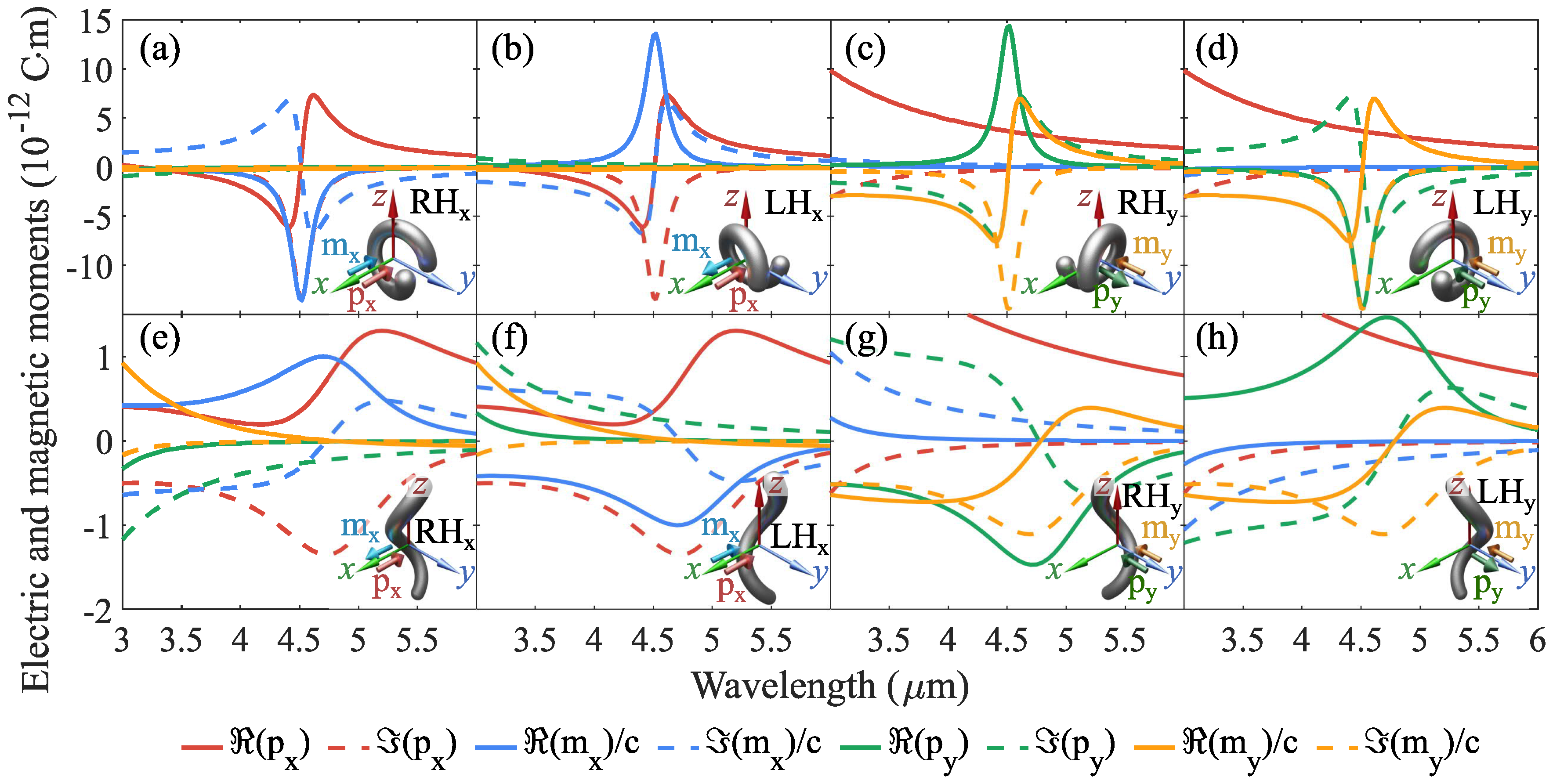
Figure 2 shows the wavelength dependence of the real and imaginary parts of individual electric and magnetic dipole moments of RH and LH horizontally-oriented and vertically-oriented helices with various orientations in the unit cell. It should be mentioned that we do not take into account the and dipole moments since we consider only normal incidence and these moments do not radiate in the z-direction. The incident plane wave is fixed and the same in all scenarios, namely, the electric field oscillates along x-axis and magnetic field along y-axis, respectively. Therefore, the helices are excited by electric and magnetic incident fields simultaneously. The structural parameters of helices are the same as depicted in Figure 1a,b. As is seen from Figure 2a,b, the RH and LH helices induce only axial dipole moments () with the different sign of the magnetic moment at the resonance wavelength of 4.5 m which corresponds to the different handedness of the helix, as mentioned before. A similar trend occurs for vertically-oriented helices at the resonance wavelength of 4.7 m. However, it has different signs of the magnetic moment between RH horizontally-oriented and RH vertically-oriented helices (Figure 2a,e). In addition, all vertically-oriented helices have the unwanted real part of the electric dipole moment () which will lead to the performance degradation for polarization conversion by metasurfaces.
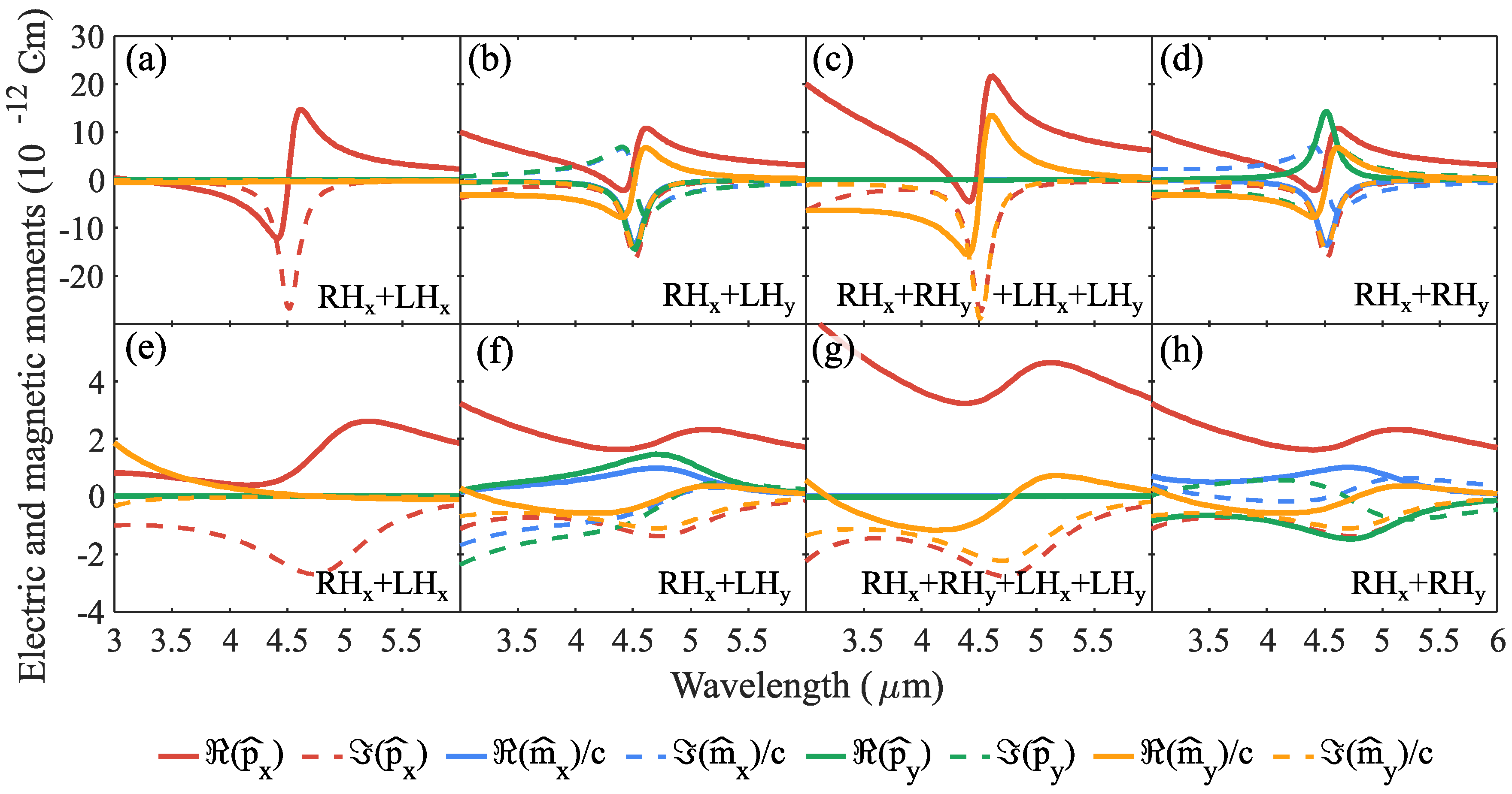
Taking into account all induced dipole moments for differently oriented RH and LH single-turn helices, it is possible to determine their optimal combination and arrangement in the unit cell to satisfy the conditions for linear polarization conversions. Figure 3 shows collective electric and magnetic dipole moments of all basic combinations of RH and LH horizontally-oriented and vertically-oriented helices (basically, unit-cell moments) which satisfy the conditions for co- and cross-polarization conversions (6), (8), (10), and (12). As seen in Figure 3a, horizontally-oriented RH and LH helices along x-axis suppress the magnetic moment () and enhance electric dipole () that fully satisfies the condition for copolarized reflectance (6) when choosing proper unit-cell area S. The combination of x-axis oriented RH and y-axis oriented LH helices (Figure 3b) leads to the fulfillment of the condition for cross-polarized reflectance (8) at the resonance wavelength and for specific area S. To achieve the copolarized transmittance, in accordance with condition (10), it is necessary to use two RH and two LH helices orthogonal to each other, as is shown in Figure 3c. The condition for cross-polarized transmittance (12) can be satisfied by using only two orthogonal helices with the same handedness (Figure 3d). The same arrangement of vertically-oriented helices in the unit cell (Figure 3e–h) should be used to meet the conditions (6), (8), (10) and (12) for desired polarization conversions.
4. Helix-Based Metasurfaces for Polarization Conversions
Metasurfaces based on helical inclusions are widely used for light manipulation in the various wavelength ranges [34,35]. In particular, metasurfaces based on vertically-oriented helices are often used to achieve wide-band linear-to-circular polarization conversion in transmission case [48,49,50]; however, they are rarely used to convert polarization from the linear to linear state. Horizontally-oriented helices are also rarely considered to convert polarization of EM waves with the exception of a few works [20,30,51]. Mainly this is due to the fact that it was challenging to fabricate in the optical range any kind of 3D helix-based metasurfaces. However, in recent years more and more attention has been paid to the fabrication of three-dimensional (3D) structures using such technologies as direct laser writing (DLW), direct ink writing, electrohydrodynamic printing, laser-assisted electrophoretic deposition, laser-induced forward transfer, local electroplating methods, laser-induced photoreduction, and electron-beam-induced deposition (EBID) [52]. Nowadays, all these methods make it possible to produce 3D helices from the THz range to the visible wavelengths.
In this section, we design helix-based metasurfaces for linear to linear polarization conversion in the reflection and transmission regimes in the mid-IR spectral range. All metasurfaces considered below consist of designed and optimized to reach the EM balance horizontally-oriented and vertically-oriented silver single-turn helices with the same structural parameters as indicted in Figure 1. Helices are distributed in the periodic lattice with the required arrangement in accordance with conditions (6), (8), (10), and (12). The metasurfaces are located on a transparent CaF substrate with the refractive index reported in [53]. Here, we model the electromagnetic response of the proposed metasurfaces using COMSOL Multiphysics 5.4 (Wave Optics Module). The simulated unit cell represents a box with two semi-infinite media: air and CaF substrate on which the helices are located. The unit cell was modeled with the Floquet boundary conditions on the side faces. We set as a source of excitation two input ports (for x- and y-polarized incident light) for the top face (-side) and two output ports (receiving x- and y-polarized light) for the bottom face (-side). The incoming linearly polarized plane wave propagates along the direction. The wavelength-dependent transmittance, reflectance, and absorbance were calculated using the S-parameters. This standard model in the simulations is carried out to investigate the polarization conversion by helix-based metasurfaces. The S-parameters characterizes the efficiency of the polarization conversion are the copolarized reflection ()/transmission () and cross-polarized reflection ()/transmission () coefficients. It is also worth considering a polarization rotation angle () and an ellipticity () of the reflected and transmitted waves for quantitative characteristics of the polarization conversion. These parameters can be expressed as follows:
The polarization rotation angle (rotation) represents the angle between the polarization plane of the incident and that of the reflected or transmitted waves, while the ellipticity denotes the polarization state of the reflected or transmitted waves. The rotation and ellipticity are equal to zero in the case of the perfect copolarized reflection or transmission coefficients. The transformation of the linearly polarized incident wave to the cross-polarized state corresponds to the case when an ellipticity is equal to zero () while the polarization plane has a rotation angle of . If the ellipticity is equal to then reflected or transmitted waves have circular polarization. Thus, we characterize the designed helix-based metasurfaces by these parameters as well as by the reflectance, transmittance, and absorbance.
4.1. Copolarized Reflection Case
Here, we design helix-based metasurfaces to achieve the copolarized reflectance in the mid-IR range. The copolarized reflection case implies that the polarization plane of fully reflected waves does not rotate with respect to the linear polarized state of incident waves. Generally, the phase and other phases can be arbitrarily. However, since we are using helices, we should choose specific values for phases. We can see that with combination shown in Figure 3a, we can satisfy requirements (6) if . The perfect copolarized reflectance is desired for applications of polarizers, wavefront shaping in reflection, and anomalous reflection and usually achieved using metasurfaces based on omega-type inclusions, crossed H-shaped metallic pattern, double-slotted metallic split-rings, and others [54,55,56]. Most of these works use three-layer metasurfaces with the metallic plane, which leads to opacity out of the resonance band. Our helix-based metasurfaces are fully transparent away from the resonance band which can be useful property for the realization of cascade multifrequency metamaterials [19,57].
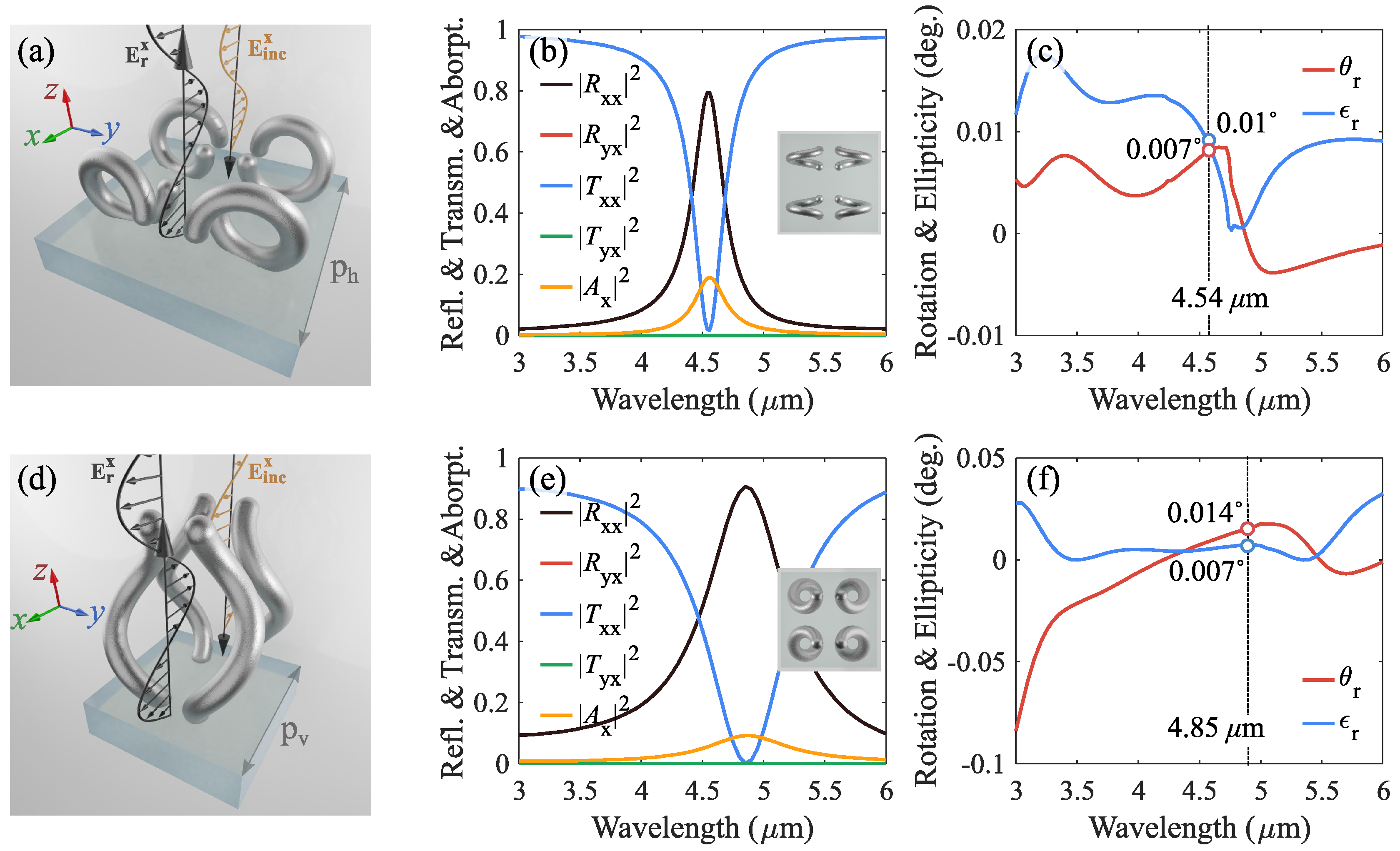
Figure 4a shows the unit cell of the metasurface with the optimal arrangement of horizontally-oriented helices for copolarized reflectance. The unit cell consists of two RH and two LH helices with an arrangement in accordance with condition (6). We use four helices instead of two, as is shown in Figure 3a, to achieve perfect uniaxial EM response for any incident linear polarization states. In other words, the properties of such a helix-based metasurface do not depend on the polarization of the incident light. The unit cell has a period of m with the interelement distance between helices equal to the half of the period. In what follows, the interelement distance is always equal to half of the period. Figure 4b demonstrates simulated reflectance, transmittance, and absorbance spectra in the wavelength range of 3–6 m. The copolarized reflectance () peak reaches a value of 0.8 at the resonance of m, while the copolarized transmittance () drops to zero. The cross-polarized reflectance and transmittance are equal to zero in the whole spectral range. A decrease in the efficiency of the developed metasurface is due to the presence of ohmic losses in silver helices that leads to the absorbance () peak of 0.18 at the resonance. As expected, the helix-based metasurface is fully transparent away from the resonance where the wave propagation reaches nearly unity at lower and higher wavelengths. Figure 4c shows the polarization rotation angle and ellipticity wavelength dependence for the reflected wave. The rotation and ellipticity reach values of and at the resonant wavelength of m, respectively. Optical isolation between co- and cross-polarized reflected waves (i.e., the optical isolation between two polarizations at the input and output waves) is around 99.99% at the resonance. This represents a high degree of spectral purity for the copolarized reflection coefficient.
Figure 4d shows the unit cell of the metasurface based on vertically-oriented helices to achieve the copolarized reflectance. Similar to the previous case, the uniaxial unit cell consists of two RH and two LH optimally arrangement helices in accordance with condition (6). The period of the metasurface is equal of m. Simulated reflectance, transmittance, and absorbance spectra of the metasurface are shown in Figure 4e. The copolarized reflectance peak reaches a value of 0.91 at the resonance of m, while the copolarized transmittance drops to zero. The absorption peak is about 0.08 at the resonance. It is interesting that vertically-oriented helix-based metasurface demonstrates better efficiency than metasurface based on horizontally-oriented helices. Due to the lower absorption this can be explained by the lower EM excitation of the vertically-oriented helices (lower amplitude of surface current density) and the broader resonance band. The rotation and ellipticity wavelength dependence of the reflected waves are given in Figure 4f. The rotation and ellipticity reach of and at the resonant wavelength, respectively. This represents nearly perfect conversion of the incident linearly polarized plane wave into the copolarized wave in the reflection regime.
4.2. Cross-Polarized Reflection Case
Next, we are aiming to design helix-based metasurfaces for unitary cross-polarized reflectance in the mid-IR range. Such metasurfaces rotate the polarization plane of the reflected waves by with respect to illuminated linearly polarized plane waves while exhibiting zero transmittance at the resonance. Typical metasurfaces for cross-polarized reflectance represent three-layer architecture consisting of some patterns and nontransparent metallic plane separated by the dielectric layer [58,59,60,61].
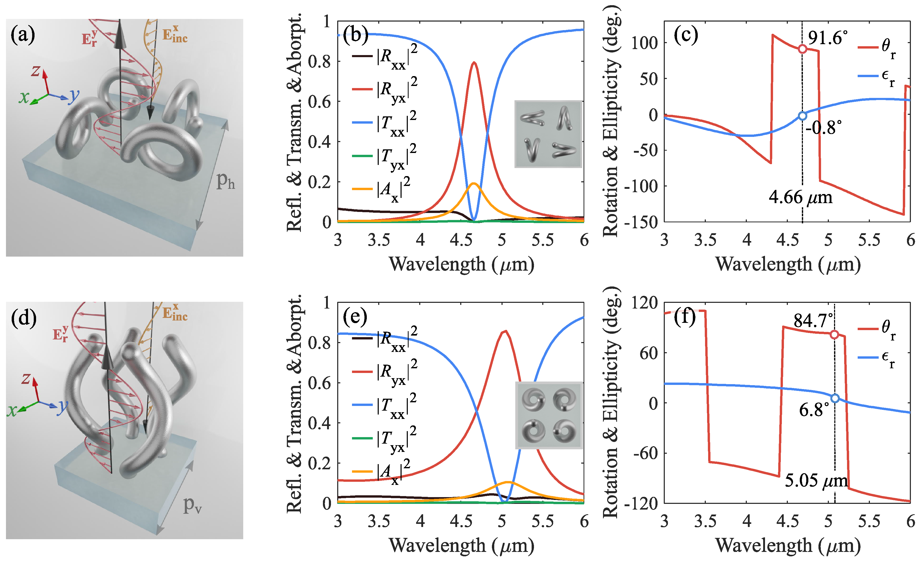
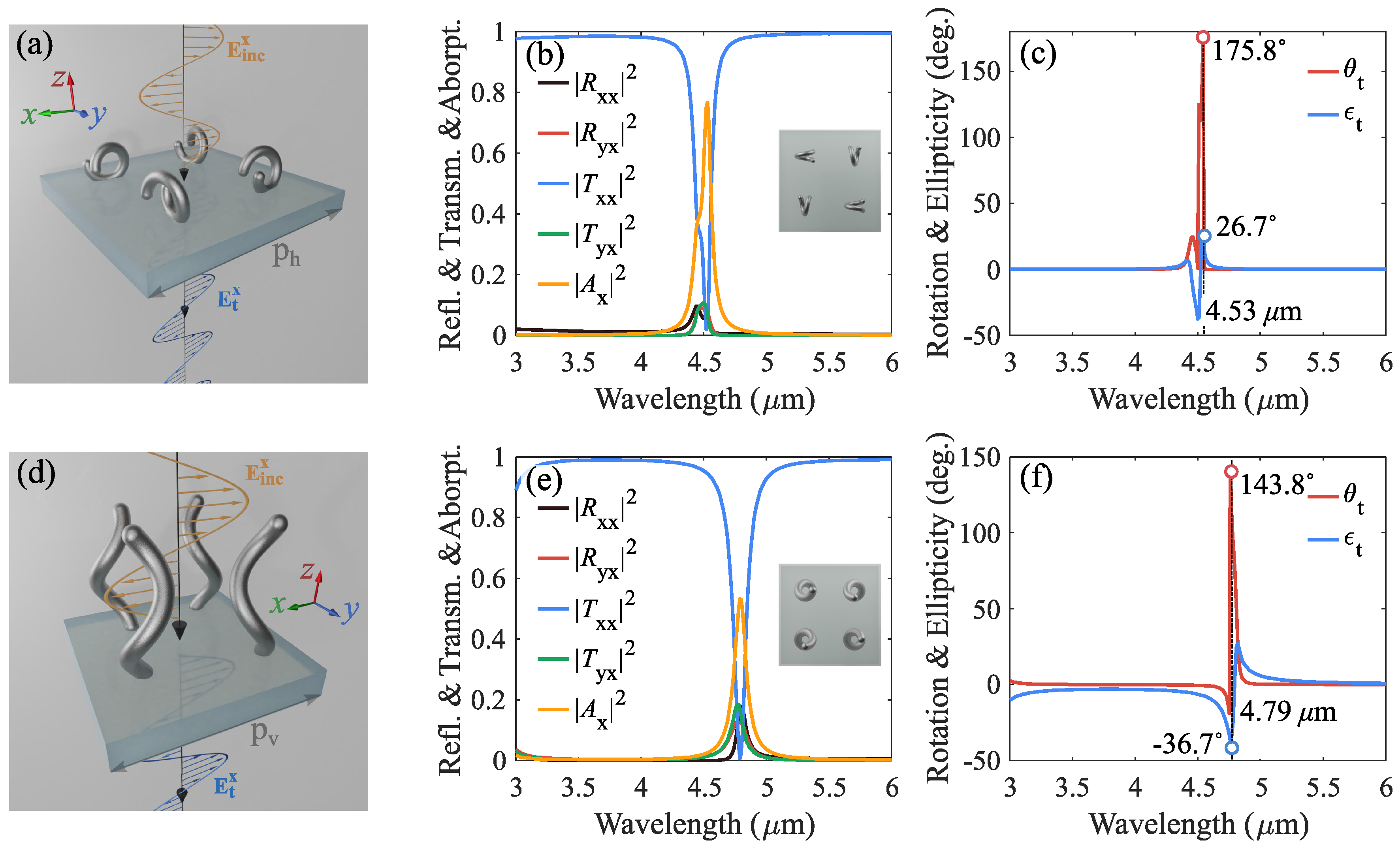
Figure 5a shows the designed unit cell of the horizontally-oriented helix-based metasurface. The unit cell is comprised of two RH and two LH single-turn helices orthogonal to each other in accordance with the condition for cross-polarized reflectance (8) corresponding to Figure 3b with phase . Using numerical simulations, the period of the metasurface is optimized and equal to m. Figure 5b shows the simulated results of reflectance, transmittance, and absorbance spectra at normal incidence. A peak of the cross-polarized reflectance reaches a value of 0.8 at the resonant wavelength of m. The copolarized transmittance drops to zero at the resonance while the copolarized reflectance and cross-polarized transmittance do not exceed 0.05 in the entire spectral range. The relative high absorption peak is about 0.18 at the resonance due to the strong excitation of horizontally-oriented helices. Figure 5c demonstrates the polarization rotation angle and ellipticity for reflected waves from the metasurface. At the resonance wavelength of m, the polarization parameters are equal to and , respectively. In accordance with obtained results, metasurface based on horizontally-oriented helices represents near-perfect polarization conversion of reflected waves to the cross-polarized state.
Figure 5d–f depict the same results for the metasurface with vertically oriented helices (the period is 1.2 m). The cross-polarized reflectance peak reaches a value of 0.86 at the resonance wavelength of m, while the absorption peak reaches a value of 0.1. The metasurface is transparent enough and away from the resonance with the transmittance of over 85%. Similar to the case for metasurfaces with copolarized reflectance, vertically-oriented helices also exhibit lower absorption properties due to the lower excitation of helices at the resonance. The rotation and ellipticity parameters reach values of and at the resonance, respectively. In that respect, the vertically-oriented helix-based metasurface demonstrates a little worse purity of the polarization conversion due to the presence of noticeable ellipticity under the polarization rotation close to 90.
The designed metasurfaces with optimal arrangement of helices for cross-polarization conversion in the reflection regime demonstrate a high performance with over 80% efficiency in accordance with the numerically simulated results. Metasurfaces are tailored for future experimental realization in the mid-IR spectral range.
4.3. Copolarized Transmission Case
Next, we propose helix-based metasurfaces for achieving copolarized transmittance in the mid-IR wavelengths. The metasurface with copolarized transmittance allows full transmission of linearly polarized incident plane waves, while maintaining the same polarization state and amplitude. As a result, the metasurface is totally transparent, while the phase of the transmitted wave varies in the range from 0 to when the frequency of incident wave changes. Alternatively, by scaling down or up helices in individual unit cells, one can fully control the phase of transmitted wave. This functionality opens up opportunities for the realization of anomalous refraction, wavefront shaping, cloaking, and others [62,63,64].
First, we attempt to design the copolarized transmitting metasurface using the same single-turn helical inclusions, as in the previous sections. Figure 6a shows the designed unit cell of metasurface comprising horizontally-oriented single-turn helices for achieving copolarized transmittance. The unit cell consists of two RH and two LH helices with an arrangement in accordance with the condition (10) for unitary copolarized transmittance as it was previously shown in the Figure 3c. The period of the metasurface is equal to m. Figure 6b shows the simulated reflectance, transmittance, and absorbance spectra at normal incidence. As is seen, the copolarized transmittance drops to value of 0.03 at the resonant wavelength of m. This undesired low copolarized transmittance is predominantly due to the very high absorbance of at the resonance. We assume that this behavior is caused not only by high excitation of the helices but also by the EM interaction between them in the lattice. This arrangement of helices leads to a very strong collective response from the metasurface. However, this result is not surprising since the obtained arrangement of helices (corresponding to the condition (10)) is also fully satisfied with the condition for total absorbance [65]. We will show below how it is possible to improve the obtained result using double-turn helices. Figure 6c shows the wavelength dependence of the polarization rotation angle and ellipticity for transmitted waves. At the resonance of m, the rotation and ellipticity are equal to and , respectively. As seen, the metasurface based on horizontally-oriented single-turn helices has a large ellipticity in addition to the near zero transparency at the resonance.
Following the same design approach, we tested the metasurface consisting of vertically-oriented helices using numerical simulation. Figure 6d–f show the design of the unit cell with reflectance, transmittance, and absorbance spectra as well as wavelength dependence of rotation and ellipticity in the spectral range of 3–6 m, respectively. As seen from Figure 6e, the copolarized transmittance is close to zero while the absorption peak reaches a value of 0.53 at the resonance wavelength of m. Moreover, the co/cross-polarized reflectance and cross-polarized transmittance spectra have a significant peak at the resonance and reach values close to 0.2. The obtained results are very similar to the previous case for horizontally-oriented helix-based metasurface. Thus, the metasurface based on vertically-oriented helices also is not suitable for the efficient copolarized conversion in the transmission regime.
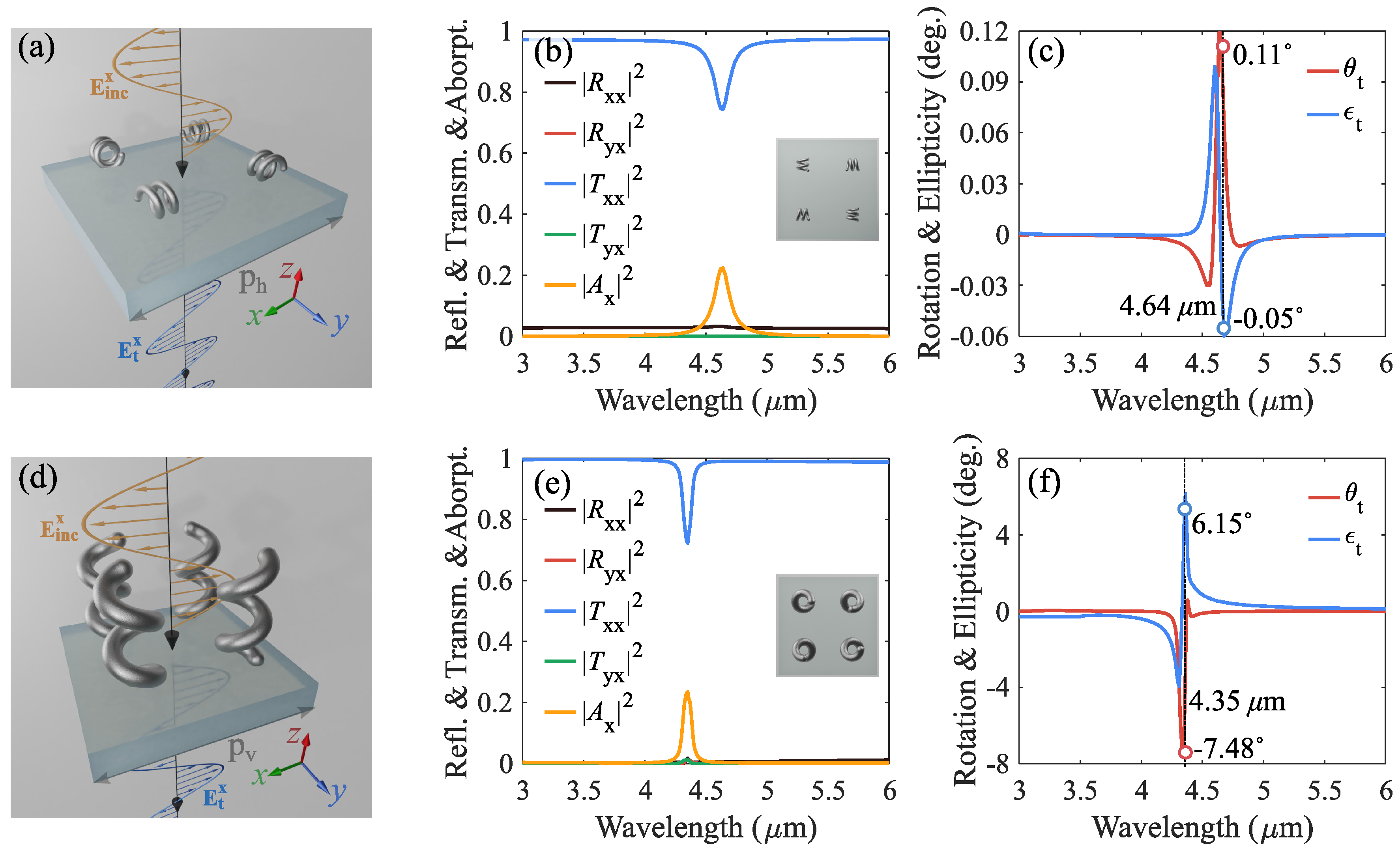
To improve the transmission level, we propose to use double-turn helices instead of single-turn ones [19,20]. Figure 7a,d show the unit cell designs of horizontally-oriented and vertically-oriented double-turn helices with structural parameters of m, m, m, m, m, m, m. All structural parameters of helices are tailored to achieve EM balance of electric and magnetic dipole moments. The arrangement of helices is the same as for single-turn helices and corresponds to the condition (10) for achieving copolarized transmittance. Figure 7b,e show the simulated reflectance, transmittance, and absorbance spectra in the range of 3–6 m. As is seen from the figures, the copolarized transmittance of horizontally-oriented helix-based metasurface increased compared to Figure 6b to the value of 0.75 at the resonance wavelength of m, while the transmittance with copolarization of vertically-oriented helices reaches 0.73 at the resonance of m. Both metasurfaces demonstrate reflectionless behavior in the entire spectral range. Figure 7c,f show the wavelength dependence of the polarization rotation angle and ellipticity of transmitted waves from corresponding metasurfaces. The horizontally-oriented helix-based metasurface demonstrates near-perfect copolarization conversion in accordance with obtained parameters of and at the resonance, respectively. The metasurface comprising of vertically-oriented double-turn helices also shows a good performance of copolarization conversion of transmitted waves with rotation and ellipticity parameters of and at the resonance wavelength of m. The obtained results indicate a good efficiency of the metasurfaces based on double-turn helices for the copolarized transmittance of incident waves.
Thus, proposed metasurfaces based on double-turn helices demonstrate high performance of copolarized transmittance in comparison with single-turn helix-based metasurfaces. This behavior can be explained by the fact that double-turn helices have a more symmetrical current distribution, which leads to a more consistent collective EM response. In other words, the different orientation and arrangement of such helices in the lattice will be more balanced with respect to the EM response of the entire metasurface. The current density of double-turn helices is higher than that in single-turn ones which should lead to high absorption properties. However, this does not occur due to the double-turn helices possess stronger localization of near fields, resulting in weaker interactions between helices in the unit cell. However, it should be mentioned that the metasurfaces based on double-turn helices are extremely difficult to realize experimentally for this wavelength range with the existing fabrication technologies.
4.4. Cross-Polarized Transmission Case
Here, we are aiming to achieve the cross-polarized transmittance using helix-based metasurfaces. Cross-polarized transmission case means that the polarization of the transmitted waves through metasurface rotates by with respect to the linear polarization of incident waves. It is possible to achieve the cross-polarized transmittance using conventional materials such as twisted nematic liquid crystals or anisotropic media [1,2,3,66,67,68]. However, these structures have the thickness much bigger than the operating wavelength, which is an important drawback for the state-of-the-art photonic devices. This drawback can be overcome using chiral metasurfaces based on a three-layer architecture that has an electrically thin thickness [7,8,9]. On another hand, the single-layer metasurface presents greater interest for application due to fabrication simplicity and for achieving extremely small thickness.
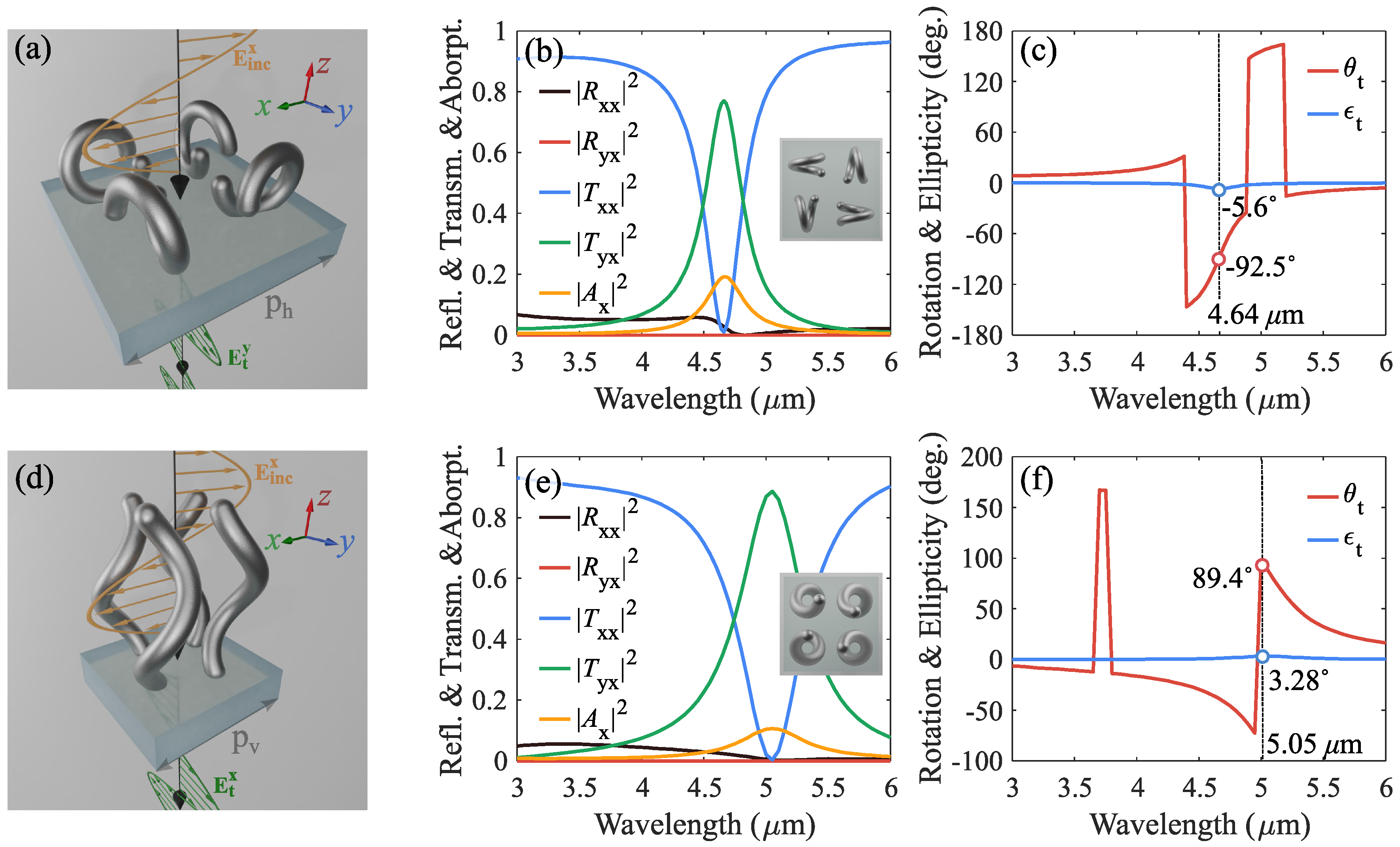
Figure 8a shows the unit cell of metasurface comprising the balanced horizontally-oriented helices for cross-polarized transmittance. The unit cell consists of four RH helices arranged in accordance with the condition for cross-polarized reflectance (12). The optimized period of the unit cell is equal to m. Figure 8b shows simulated reflectance, transmittance, and absorbance spectra at normal incidence. The helix-based metasurface demonstrates a cross-polarized transmittance peak of at the resonant wavelength of m, while the co- and cross-reflectance do not exceed 6% in the entire range. The absorption peak reaches a value of 0.19 at the resonance. Figure 8c shows the polarization rotation angle and ellipticity of transmitted waves. The rotation and ellipticity at the resonance wavelength are equal to and , respectively. Therefore, the metasurface based on horizontally-oriented helices demonstrates a clear polarization rotation by for linear polarized transmitted waves at the resonance wavelength.
Figure 8d–f depict the same results for the metasurface with vertically oriented helices (the period is m). The cross-polarized transmittance reaches a peak value of 0.89 at the resonance wavelength of m while the absorption peak reaches a value of 0.1. The sum of co-and cross-polarized reflectance of metasurface does not exceed a value of 5.5% in the whole spectral range. At the resonance wavelength of m, the rotation and ellipticity reach values of and , respectively. As a result, the vertically-oriented helix-based metasurface has a good performance with the pure cross-polarization transmittance in the mid-IR spectral range.
We have designed metasurfaces based on horizontally-oriented and vertically-oriented metallic helices with balanced EM response and optimal arrangement of helices in the unit cell for efficient co- and cross-polarization conversion of transmitted and reflected waves in the mid-IR spectral range. All simulated data of proposed metasurfaces are summarized in Table 1.
5. Conclusions
In this study, we have proposed Huygens’ metasurfaces based on horizontally-oriented and vertically-oriented RH and LH metallic helices for the manipulation of linearly polarization EM waves in reflection and transmission regimes in the mid-IR range. Using numerical simulations, resonant helices were tailored to produce balanced electric and magnetic dipole moments in accordance with the conditions for impedance matching. Next, we have proposed the analytic approach for the determination of the required orientation and excitation of dipole moments in the unit cell of metasurface in accordance with conditions (6), (8), (10), and (12) for efficient co- and cross-polarization conversion of transmitted and reflected waves. Based on this approach, we determined the optimal arrangement of horizontally-oriented and vertically-oriented helices in the unit cell. As a result, we have designed helix-based metasurfaces to achieve the near-perfect co-/cross-polarized reflectance and transmittance at the resonance wavelength. Designed metasurfaces exhibit a good performance over 75% and near-perfect polarization conversion of reflected and transmitted waves at the resonance. In addition, all metasurfaces are highly transparent outside of the resonance band and the total reflectance does not exceed 5.5%. This feature provides an additional advantage for potential realization of metasurfaces as parts of cascade multifrequency devices [19]. In the future, our helix-based metasurfaces can be realized using various 3D fabrication technologies and may enable applications for the polarization manipulation of EM waves in THz and IR spectral ranges.
Author Contributions
Conceptualization, I.F. (Ihar Faniayeu), V.A.; software, I.F. (Ihar Faniayeu); investigation, I.F. (Ihar Faniayeu), I.F. (Ivan Fanyaev); writing—original draft preparation, I.F. (Ihar Faniayeu), V.A.; visualization, I.F. (Ihar Faniayeu); supervision, V.A. All authors have read and agreed to the published version of the manuscript.
Funding
This research received no external funding.
Conflicts of Interest
The authors declare no conflict of interest.
References
- Jem, Y.J.; Lin, C.F.; Lin, M.J. Slanted S-shaped nano-columnar thin films for broadband and wide-angle polarization conversion. Opt. Mater. Express 2011, 1, 525–534. [Google Scholar]
- Kim, J.; Komanduri, R.K.; Lawler, K.F.; Kekas, D.J.; Escuti, M.J. Efficient and monolithic polarization conversion system based on a polarization grating. Appl. Opt. 2012, 51, 4852–4857. [Google Scholar] [CrossRef] [PubMed] [Green Version]
- Arikawa, T.; Wang, X.; Belyanin, A.A.; Kono, J. Giant tunable Faraday effect in a semiconductor magneto-plasma for broadband terahertz polarization optics. Opt. Express 2012, 20, 19484–19492. [Google Scholar] [CrossRef] [PubMed] [Green Version]
- Fowles, G.R. Introduction to Modern Optics; Courier Corporation: New York, NY, USA, 1989; p. 336. [Google Scholar]
- Zhao, R.; Zhang, L.; Zhou, J.; Koschny, T.; Soukoulis, C.M. Conjugated gammadion chiral metamaterial with uniaxial optical activity and negative refractive index. Phys. Rev. B 2011, 83, 035105. [Google Scholar] [CrossRef] [Green Version]
- Yan, S.; Vandenbosch, G.A. Compact circular polarizer based on chiral twisted double split-ring resonator. Appl. Phys. Lett. 2013, 102, 103503. [Google Scholar] [CrossRef]
- Li, Y.; Zhang, J.; Qu, S.; Wang, J.; Zheng, L.; Pang, Y.; Xu, Z.; Zhang, A. Achieving wide-band linear-to-circular polarization conversion using ultra-thin bi-layered metasurfaces. J. Appl. Phys. 2015, 117, 044501. [Google Scholar] [CrossRef]
- Ye, Y.; He, S. 90° polarization rotator using a bilayered chiral metamaterial with giant optical activity. Appl. Phys. Lett. 2010, 96, 203501. [Google Scholar] [CrossRef]
- Mutlu, M.; Ozbay, E. A transparent 90° polarization rotator by combining chirality and electromagnetic wave tunneling. Appl. Phys. Lett. 2012, 100, 051909. [Google Scholar] [CrossRef] [Green Version]
- Cong, L.; Cao, W.; Zhang, X.; Tian, Z.; Gu, J.; Singh, R.; Han, J.; Zhang, W. A perfect metamaterial polarization rotator. Appl. Phys. Lett. 2013, 103, 171107. [Google Scholar] [CrossRef]
- Chen, M.; Kim, M.; Wong, A.M.; Eleftheriades, G.V. Huygens’ metasurfaces from microwaves to optics: A review. Nanophotonics 2018, 7, 1207–1231. [Google Scholar] [CrossRef]
- Rockstuhl, C.; Zentgraf, T.; Guo, H.; Liu, N.; Etrich, C.; Loa, I.; Syassen, K.; Kuhl, J.; Lederer, F.; Giessen, H. Resonances of split-ring resonator metamaterials in the near infrared. Appl. Phys. B 2006, 84, 219–227. [Google Scholar] [CrossRef]
- Liu, N.; Giessen, H. Coupling effects in optical metamaterials. Angew. Chem. Int. Ed. 2010, 49, 9838–9852. [Google Scholar] [CrossRef] [PubMed]
- Liu, N.; Guo, H.; Fu, L.; Kaiser, S.; Schweizer, H.; Giessen, H. Plasmon hybridization in stacked cut-wire metamaterials. Adv. Mater. 2007, 19, 3628–3632. [Google Scholar] [CrossRef]
- Jia, S.L.; Wan, X.; Bao, D.; Zhao, Y.J.; Cui, T.J. Independent controls of orthogonally polarized transmitted waves using a Huygens metasurface. Laser Phot. Rev. 2015, 9, 545–553. [Google Scholar] [CrossRef]
- Zhang, L.; Ding, J.; Zheng, H.; An, S.; Lin, H.; Zheng, B.; Du, Q.; Yin, G.; Michon, J.; Zhang, Y.; et al. Ultra-thin high-efficiency mid-infrared transmissive Huygens meta-optics. Nat. Commun. 2018, 9, 1–9. [Google Scholar] [CrossRef] [PubMed] [Green Version]
- Sun, Z.; Sima, B.; Zhao, J.; Feng, Y. Electromagnetic polarization conversion based on huygens’ metasurfaces with coupled electric and magnetic resonances. Opt. Express 2019, 27, 11006–11017. [Google Scholar] [CrossRef]
- Asadchy, V.S.; Faniayeu, I.A.; Ra’di, Y.; Khakhomov, S.A.; Semchenko, I.V.; Tretyakov, S.A. Broadband reflectionless metasheets: Frequency-selective transmission and perfect absorption. Phys. Rev. X 2015, 5, 031005. [Google Scholar] [CrossRef]
- Elsakka, A.A.; Asadchy, V.S.; Faniayeu, I.A.; Tcvetkova, S.N.; Tretyakov, S.A. Multifunctional cascaded metamaterials: Integrated transmitarrays. IEEE Trans. Antennas Propag. 2016, 64, 4266–4276. [Google Scholar] [CrossRef]
- Cuesta, F.S.; Faniayeu, I.A.; Asadchy, V.S.; Tretyakov, S.A. Planar broadband Huygens’ metasurfaces for wave manipulations. IEEE Trans. Antennas Propag. 2018, 66, 7117–7127. [Google Scholar] [CrossRef] [Green Version]
- Cong, L.; Srivastava, Y.K.; Singh, R. Near-Field Inductive Coupling Induced Polarization Control in Metasurfaces. Adv. Opt. Mater. 2016, 4, 848–852. [Google Scholar] [CrossRef]
- Yue, S.; Liu, S.; Hou, Y.; Zhang, Z. Tailorable chiral optical response through coupling among plasmonic meta-atoms with distinct shapes. Opt. Lett. 2018, 43, 1111–1114. [Google Scholar] [CrossRef] [PubMed]
- Burckel, D.B.; Adomanis, B.M.; Sinclair, M.B.; Campione, S. Three-dimensional cut wire pair behavior and controllable bianisotropic response in vertically oriented meta-atoms. Opt. Express 2017, 25, 32198–32205. [Google Scholar] [CrossRef] [PubMed]
- Liu, N.; Guo, H.; Fu, L.; Kaiser, S.; Schweizer, H.; Giessen, H. Three-dimensional photonic metamaterials at optical frequencies. Nat. Mater. 2008, 7, 31–37. [Google Scholar] [CrossRef] [PubMed]
- Zhou, J.; Dong, J.; Wang, B.; Koschny, T.; Kafesaki, M.; Soukoulis, C.M. Negative refractive index due to chirality. Phys. Rev. B 2009, 79, 121104. [Google Scholar] [CrossRef] [Green Version]
- Ibach, H.; Lüth, H. Solid-State Physics: An Introduction to Principles of Materials Science; Springer Science & Business Media: New York, NY, USA, 2013; p. 495. [Google Scholar]
- Jenkins, S.D.; Papasimakis, N.; Savo, S.; Zheludev, N.I.; Ruostekoski, J. Strong interactions and subradiance in disordered metamaterials. Phys. Rev. B 2018, 98, 245136. [Google Scholar] [CrossRef] [Green Version]
- Li, T.; Liu, H.; Wang, F.M.; Dong, Z.G.; Zhu, S.N.; Zhang, X. Coupling effect of magnetic polariton in perforated metal/dielectric layered metamaterials and its influence on negative refraction transmission. Opt. Express 2006, 14, 11155–11163. [Google Scholar] [CrossRef]
- Rana, G.; Deshmukh, P.; Palkhivala, S.; Gupta, A.; Duttagupta, S.P.; Prabhu, S.S.; Achanta, V.; Agarwal, G.S. Quadrupole-quadrupole interactions to control plasmon-induced transparency. Phys. Rev. Appl. 2018, 9, 064015. [Google Scholar] [CrossRef]
- Niemi, T.; Karilainen, A.O.; Tretyakov, S.A. Synthesis of polarization transformers. IEEE Trans. Antennas Propag. 2013, 61, 3102–3111. [Google Scholar] [CrossRef]
- Gansel, J.K.; Thiel, M.; Rill, M.S.; Decker, M.; Bade, K.; Saile, V.; von Freymann, G.; Linden, S.; Wegener, M. Gold helix photonic metamaterial as broadband circular polarizer. Science 2009, 325, 1513–1515. [Google Scholar] [CrossRef]
- Gansel, J.K.; Wegener, M.; Burger, S.; Linden, S. Gold helix photonic metamaterials: A numerical parameter study. Opt. Express 2010, 18, 1059–1069. [Google Scholar] [CrossRef] [Green Version]
- Semchenko, I.V.; Khakhomov, S.A.; Samofalov, A.L. Transformation of the polarization of electromagnetic waves by helical radiators. J. Commun. Technol. Electr. 2007, 52, 850–855. [Google Scholar] [CrossRef]
- Fernandez-Corbaton, I.; Fruhnert, M.; Rockstuhl, C. Objects of maximum electromagnetic chirality. Phys. Rev. X 2016, 6, 031013. [Google Scholar] [CrossRef]
- Wong, J.P.; Epstein, A.; Eleftheriades, G.V. Reflectionless wide-angle refracting metasurfaces. IEEE Antennas Wirel. Propag. Lett. 2015, 15, 1293–1296. [Google Scholar] [CrossRef]
- Chen, M.; Abdo-Sánchez, E.; Epstein, A.; Eleftheriades, G.V. Theory, design, and experimental verification of a reflectionless bianisotropic Huygens’ metasurface for wide-angle refraction. Phys. Rev. B 2018, 97, 125433. [Google Scholar] [CrossRef] [Green Version]
- Londoño, M.; Sayanskiy, A.; Araque-Quijano, J.L.; Glybovski, S.B.; Baena, J.D. Broadband Huygens’ metasurface based on hybrid resonances. Phys. Rev. Appl. 2018, 10, 034026. [Google Scholar] [CrossRef] [Green Version]
- Jaggard, D.L.; Mickelson, A.R.; Papas, C.H. On electromagnetic waves in chiral media. Appl. Phys. 1979, 18, 211–216. [Google Scholar] [CrossRef]
- Grahn, P.; Shevchenko, A.; Kaivola, M. Electromagnetic multipole theory for optical nanomaterials. New J. Phys. 2012, 14, 093033. [Google Scholar] [CrossRef]
- Babar, S.; Weaver, J.H. Optical constants of Cu, Ag, and Au revisited. Appl. Opt. 2015, 54, 477–481. [Google Scholar] [CrossRef]
- Farmahini-Farahani, M.; Mosallaei, H. Birefringent reflectarray metasurface for beam engineering in infrared. Opt. Lett. 2013, 38, 462–464. [Google Scholar] [CrossRef]
- Pors, A.; Nielsen, M.G.; Eriksen, R.L.; Bozhevolnyi, S.I. Broadband focusing flat mirrors based on plasmonic gradient metasurfaces. Nano Lett. 2013, 13, 829–834. [Google Scholar] [CrossRef]
- Grady, N.K.; Heyes, J.E.; Chowdhury, D.R.; Zeng, Y.; Reiten, M.T.; Azad, A.K.; Taylor, A.J.; Dalvit, D.A.; Chen, H.T. Terahertz metamaterials for linear polarization conversion and anomalous refraction. Science 2013, 340, 1304–1307. [Google Scholar] [CrossRef] [PubMed] [Green Version]
- Khorasaninejad, M.; Chen, W.T.; Devlin, R.C.; Oh, J.; Zhu, A.Y.; Capasso, F. Metalenses at visible wavelengths: Diffraction-limited focusing and subwavelength resolution imaging. Science 2016, 352, 1190–1194. [Google Scholar] [CrossRef] [PubMed] [Green Version]
- Ni, X.; Emani, N.K.; Kildishev, A.V.; Boltasseva, A.; Shalaev, V.M. Broadband light bending with plasmonic nanoantennas. Science 2012, 335, 427. [Google Scholar] [CrossRef] [PubMed] [Green Version]
- Ra’di, Y.; Asadchy, V.S.; Tretyakov, S.A. One-way transparent sheets. Phys. Rev. B 2014, 89, 075109. [Google Scholar] [CrossRef] [Green Version]
- Asadchy, V.S.; Ra’di, Y.; Vehmas, J.; Tretyakov, S.A. Functional metamirrors using bianisotropic elements. Phys. Rev. Lett. 2015, 114, 095503. [Google Scholar] [CrossRef] [Green Version]
- Wang, Z.; Cheng, F.; Winsor, T.; Liu, Y. Optical chiral metamaterials: A review of the fundamentals, fabrication methods and applications. Nanotechnology 2016, 27, 412001. [Google Scholar] [CrossRef] [Green Version]
- Passaseo, A.; Esposito, M.; Cuscunà, M.; Tasco, V. Materials and 3D designs of helix nanostructures for chirality at optical frequencies. Adv. Opt. Mater. 2017, 5, 1601079. [Google Scholar] [CrossRef]
- Gansel, J.K.; Latzel, M.; Frölich, A.; Kaschke, J.; Thiel, M.; Wegener, M. Tapered gold-helix metamaterials as improved circular polarizers. Appl. Phys. Lett. 2012, 100, 101109. [Google Scholar] [CrossRef]
- Faniayeu, I.; Khakhomov, S.; Semchenko, I.; Mizeikis, V. Highly transparent twist polarizer metasurface. Appl. Phys. Lett. 2017, 111, 111108. [Google Scholar] [CrossRef]
- Hirt, L.; Reiser, A.; Spolenak, R.; Zambelli, T. Additive manufacturing of metal structures at the micrometer scale. Adv. Mater. 2017, 29, 1604211. [Google Scholar] [CrossRef]
- Malitson, I.H. A redetermination of some optical properties of calcium fluoride. Appl. Opt. 1963, 2, 1103–1107. [Google Scholar] [CrossRef]
- Asadchy, V.; Albooyeh, M.; Tretyakov, S. Optical metamirror: All-dielectric frequency-selective mirror with fully controllable reflection phase. JOSA B 2016, 33, A16–A20. [Google Scholar] [CrossRef]
- Yang, J.; Qu, S.; Ma, H.; Wang, J.; Sui, S.; Zheng, Q.; Chen, H.; Pang, Y. Ultra-broadband co-polarization anomalous reflection metasurface. Appl. Phys. A 2017, 123, 537. [Google Scholar] [CrossRef]
- Fu, C.; Sun, Z.; Han, L.; Liu, C.; Sun, T.; Chu, P.K. High-efficiency dual-frequency reflective linear polarization converter based on metasurface for microwave bands. Appl. Sci. 2019, 9, 1910. [Google Scholar] [CrossRef] [Green Version]
- Khorasaninejad, M.; Capasso, F. Metalenses: Versatile multifunctional photonic components. Science 2017, 358, eaam8100. [Google Scholar] [CrossRef] [PubMed] [Green Version]
- Hanfling, J.; Jerinic, G.; Lewis, L. Twist reflector design using E-type and H-type modes. IEEE Trans. Antennas Propag. 1981, 29, 622–629. [Google Scholar] [CrossRef]
- Naqvi, S.S.H.; Gallagher, N.C. Analysis of a strip-grating twist reflector. JOSA A 1990, 7, 1723–1729. [Google Scholar] [CrossRef]
- Cheng, Y.Z.; Withayachumnankul, W.; Upadhyay, A.; Headland, D.; Nie, Y.; Gong, R.Z.; Bhaskaran, M.; Sriram, S.; Abbott, D. Ultrabroadband reflective polarization convertor for terahertz waves. Appl. Phys. Lett. 2014, 105, 181111. [Google Scholar] [CrossRef]
- Ma, H.F.; Wang, G.Z.; Kong, G.S.; Cui, T.J. Broadband circular and linear polarization conversions realized by thin birefringent reflective metasurfaces. Opt. Mater. Express 2014, 4, 1717–1724. [Google Scholar] [CrossRef]
- Jang, M.; Horie, Y.; Shibukawa, A.; Brake, J.; Liu, Y.; Kamali, S.M.; Arbabi, A.; Ruan, H.; Faraon, A.; Yang, C. Wavefront shaping with disorder-engineered metasurfaces. Nat. Phot. 2018, 12, 84–90. [Google Scholar] [CrossRef]
- Cheng, H.; Chen, S.; Yu, P.; Liu, W.; Li, Z.; Li, J.; Xie, B.; Tian, J. Dynamically tunable broadband infrared anomalous refraction based on graphene metasurfaces. Adv. Opt. Mater. 2015, 3, 1744–1749. [Google Scholar] [CrossRef]
- Cai, W.; Chettiar, U.K.; Kildishev, A.V.; Shalaev, V.M. Optical cloaking with metamaterials. Nat. Phot. 2007, 1, 224–227. [Google Scholar] [CrossRef] [Green Version]
- Ra’di, Y.; Asadchy, V.S.; Tretyakov, S.A. Total absorption of electromagnetic waves in ultimately thin layers. IEEE Trans. Antennas Propag. 2013, 61, 4606–4614. [Google Scholar] [CrossRef]
- Han, J.; Li, H.; Fan, Y.; Wei, Z.; Wu, C.; Cao, Y.; Yu, X.; Li, F.; Wang, Z. An ultrathin twist-structure polarization transformer based on fish-scale metallic wires. Appl. Phys. Lett. 2011, 98, 151908. [Google Scholar] [CrossRef] [Green Version]
- Wei, Z.; Cao, Y.; Fan, Y.; Yu, X.; Li, H. Broadband polarization transformation via enhanced asymmetric transmission through arrays of twisted complementary split-ring resonators. Appl. Phys. Lett. 2011, 99, 221907. [Google Scholar] [CrossRef] [Green Version]
- Cheng, Y.; Nie, Y.; Wang, X.; Gong, R. An ultrathin transparent metamaterial polarization transformer based on a twist-split-ring resonator. Appl. Phys. A 2013, 111, 209–215. [Google Scholar] [CrossRef] [Green Version]
Figure 1.
(a,b) Illustration of horizontally-oriented and vertically-oriented single-turn helices with the following structural parameters: m, m, m, m, m. (c,d) Wavelength dependence of electric and magnetic dipole moments under the parametric scan of the helix pitch.
Figure 1.
(a,b) Illustration of horizontally-oriented and vertically-oriented single-turn helices with the following structural parameters: m, m, m, m, m. (c,d) Wavelength dependence of electric and magnetic dipole moments under the parametric scan of the helix pitch.

Figure 2.
The wavelength dependence of the real and imaginary parts of individual electric and magnetic dipole moments under the different orientation of RH and LH (a–d) horizontally oriented helices and (e–h) vertically oriented helices. The helices are illuminated by the linearly polarized incident plane wave propagating along the -direction with the polarization state (3). The orientation of helices with main induced dipole moments are shown in the inset of each plot. The designations RH and LH mean that the helix with RH or LH handednesses is oriented along the -axes relative to the plane of the metasurface.

Figure 3.
The real and imaginary parts of electric and magnetic dipole moments of the required combination and arrangement of RH and LH helices for polarization conversion in accordance with conditions (6), (8), (10) and (12) for (a–d) horizontally oriented and (e–h) vertically oriented helices, respectively.

Figure 4.
(a) The unit cell of a metasurface designed for the copolarized reflection regime. The unit cell consists of horizontally-oriented helices with the lattice period of m. (b) Simulated reflectance, transmittance, and absorbance spectra with corresponding polarization states. The top view of the unit cell is depicted in the inset. (c) The rotation and ellipticity wavelength dependence of the corresponding metasurface. (d) The unit cell of a metasurface consists of vertically oriented helices with a lattice period of m for copolarized reflectance. (e) Co- and cross-polarized reflectance, transmittance, and absorbance spectra with the top view of the unit cell in the inset. (f) The rotation and ellipticity wavelength dependence of the vertically oriented helix-based metasurface.

Figure 5.
(a) The designed unit cell of a metasurface consists of horizontally-oriented helices with the lattice period of m for cross-polarized reflection regime. (b) Reflectance, transmittance, and absorbance spectra with the top view of the unit cell in the inset. (c) The rotation and ellipticity wavelength dependence of the metasurface. (d) The unit cell of a metasurface consists of vertically oriented helices with a lattice period of m. (e) Co- and cross-polarized reflectance, transmittance, and absorbance spectra with the top view of the unit cell in the inset. (f) The rotation and ellipticity wavelength dependence of the corresponding metasurface.

Figure 6.
(a) The unit cell of a metasurface based on horizontally-oriented helices with the lattice period of m for copolarized transmission regime. (b) Co- and cross-polarized reflectance, transmittance, and absorbance spectra with the top view of the unit cell in the inset. (c) The polarization rotation angle and ellipticity of transmitted waves. (d) The unit cell of a metasurface consists of vertically oriented helices with a lattice period of m for copolarized transmittance. (e) Reflectance, transmittance, and absorbance spectra with the top view of the unit cell in the inset. (f) The rotation and ellipticity wavelength dependence of the metasurface based on vertically-oriented helices.

Figure 7.
(a) The unit cell with horizontally-oriented double-turn helices with the lattice period of m for copolarized transmission regime. (b) Reflectance, transmittance, and absorbance spectra with the top view of the unit cell in the inset. (c) The polarization rotation angle and ellipticity of transmitted waves. (d) The unit cell of a metasurface consists of vertically oriented helices with a lattice period of m. (e) Reflectance, transmittance, and absorbance with the top view of the unit cell in the inset. (f) The rotation and ellipticity wavelength dependence of the metasurface based on vertically-oriented helices.

Figure 8.
(a) The unit cell of a metasurface designed for the cross-polarized transmission regime. The unit cell consists of horizontally-oriented helices with the lattice period of m. (b) Simulated polarized reflectance, transmittance, and absorbance spectra at normal incidence with depicted top view of the unit cell in the inset. (c) The rotation and ellipticity wavelength dependence of the metasurface. (d) The unit cell of a metasurface based on vertically-oriented helices with a lattice period of m for cross-polarized transmittance. (e) Co- and cross-polarized reflectance, transmittance, and absorbance spectra with the top view of the unit cell in the inset. (f) The rotation and ellipticity wavelength dependence of the metasurface.


Table 1.
Numerically calculated characteristics of the metasurfaces.
| Metasurfaces | , deg. | , deg. | , deg. | , deg. | , μm | |||||
|---|---|---|---|---|---|---|---|---|---|---|
| Figure 4a–c | 0.8 | 0 | 0.02 | 0 | 0.18 | 0.007 | 0.01 | – | – | 4.54 |
| Figure 4d–f | 0.91 | 0 | 0.01 | 0 | 0.08 | 0.014 | 0.07 | – | – | 4.85 |
| Figure 5a–c | 0.01 | 0.8 | 0.01 | 0 | 0.18 | 91.6 | −0.8 | – | – | 4.66 |
| Figure 5d–f | 0.03 | 0.86 | 0.01 | 0 | 0.1 | 84.7 | 6.8 | – | – | 5.05 |
| Figure 7a–c | 0.03 | 0 | 0.75 | 0 | 0.22 | – | – | 0.11 | −0.05 | 4.64 |
| Figure 7d–f | 0.01 | 0.01 | 0.73 | 0.01 | 0.24 | – | – | −7.48 | 6.15 | 4.35 |
| Figure 8a–c | 0.03 | 0 | 0.02 | 0.76 | 0.19 | – | – | −92.5 | −5.6 | 4.64 |
| Figure 8d–f | 0 | 0 | 0.01 | 0.89 | 0.1 | – | – | 89.4 | 3.28 | 5.05 |
© 2020 by the authors. Licensee MDPI, Basel, Switzerland. This article is an open access article distributed under the terms and conditions of the Creative Commons Attribution (CC BY) license (http://creativecommons.org/licenses/by/4.0/).
Share and Cite
MDPI and ACS Style
Faniayeu, I.; Asadchy, V.; Fanyaev, I. Polarization Control with Helical Metasurfaces. Crystals 2020, 10, 726. https://doi.org/10.3390/cryst10090726
AMA Style
Faniayeu I, Asadchy V, Fanyaev I. Polarization Control with Helical Metasurfaces. Crystals. 2020; 10(9):726. https://doi.org/10.3390/cryst10090726
Chicago/Turabian StyleFaniayeu, Ihar, Viktar Asadchy, and Ivan Fanyaev. 2020. "Polarization Control with Helical Metasurfaces" Crystals 10, no. 9: 726. https://doi.org/10.3390/cryst10090726
Note that from the first issue of 2016, this journal uses article numbers instead of page numbers. See further details here.