Introduction to Plasma Electrolytic Oxidation—An Overview of the Process and Applications


1
Materials and Surface Engineering Group, Institute of Materials Science and Engineering, Chemnitz University of Technology, 09107 Chemnitz, Germany
2
Department of Corrosion Protection and Testing, EXCOR Korrosionsforschung GmbH, Magdeburger Strae 58, 01067 Dresden, Germany
3
Meotec GmbH, Triwo Technopark Aachen, Philipsstraße 8, 52001 Aachen, Germany
*
Author to whom correspondence should be addressed.
Coatings 2020, 10(7), 628; https://doi.org/10.3390/coatings10070628
Submission received: 28 April 2020
/
Revised: 24 June 2020
/
Accepted: 28 June 2020
/
Published: 30 June 2020
(This article belongs to the Special Issue Plasma Electrolytic Oxidation (PEO) Coatings)
Abstract
:Plasma electrolytic oxidation (PEO), also called micro-arc oxidation (MAO), is an innovative method in producing oxide-ceramic coatings on metals, such as aluminum, titanium, magnesium, zirconium, etc. The process is characterized by discharges, which develop in a strong electric field, in a system consisting of the substrate, the oxide layer, a gas envelope, and the electrolyte. The electric breakdown in this system establishes a plasma state, in which, under anodic polarization, the substrate material is locally converted to a compound consisting of the substrate material itself (including alloying elements) and oxygen in addition to the electrolyte components. The review presents the process kinetics according to the existing models of the discharge phenomena, as well as the influence of the process parameters on the process, and thus, on the resulting coating properties, e.g., morphology and composition.
1. Introduction
Plasma electrolytic discharge phenomena were first described by Sluginov around 1880 [1]. In the 1920s, these were systematically examined by Güntherschulze and Betz as an aspect of the development of electrolytic capacitors [2]. In the early 1970s, Brown and co-workers derived a method from the phenomena described to produce ceramic conversion layers on Al substrates in alkaline electrolytes, which they referred to as Anodic Spark Deposition (ASD) [3]. In the 1980s and 1990s, the working groups of Snezhko, Markov, Kurze and others made further progress, which led to the first practical applications [4,5,6].
Since then, the technological and commercial introduction of the PEO into practice by specialized companies has succeeded: Keronite (GB), Meotec, Innovent, AaST, Cermanod (DE), Hirtenberge (AT), Tekniker (ES) IBC (US), Manel (RU) MAO Environmental Production Technology (CN), the related specialist literature began to split up thematically. To respect the immense research activity in the field of PEO, current reviews are increasingly dealing with key topics such as special substrate materials [7,8,9], particle incorporation [10,11], selected technological properties [12,13] and characteristics of the discharge phenomena [14,15]. While excellent reviews from past decades [16,17] on the basics of the PEO exist, their coverage of current developments is limited.
The present work should, therefore, provide an introduction to the topic and convey both, the fundamental basics and the approaches of modern development trends and form a link to current fields of application.
2. Principles of Plasma Electrolytic Oxidation
Plasma electrolytic oxidation (PEO) is also referred to as micro-arc oxidation (MAO), anodic spark deposition (ASD), plasma chemical oxidation (PCO), or anodic oxidation by spark discharge (ANOF, German: anodische Oxidation unter Funkenentladung). It is a conversion coating process for the surface refinement of several metallic materials, which tend to passivity in adequate aqueous electrolytes. In the first decade of the 21st century, PEO had also been developed for iron-based materials, which exhibit usually a poor passivation behavior. Table 1 shows a brief overview about literature known PEO processes, categorized according to application and substrate material.
The process is characterized by discharge, which develop under a strong electric field in a system consisting of the substrate, the oxide layer, a gas envelope, and the electrolyte, and it specifically determines the morphology, as well as the composition of the produced coatings. The electric breakdown in this system establishes a plasma state, in which, under anodic polarization, the substrate material is converted to a compound, comprised of the substrate material itself (including alloying elements), oxygen, and the electrolyte components.
The PEO process originates in the anodic oxidation of metals. When a metal electrode is polarized anodically in an electrolyte, different reactions are possible. A metal electrode, which is insoluble in the electrolyte, will lead to the evolution of oxygen (water electrolysis). If the metal electrode is soluble in the electrolyte, salts comprised of the electrode material and electrolyte components will occur, and the electrode will be consumed. The third possible reaction is the reaction of the anode material with the oxygen provided from the electrolyte to form a thin passive film, which itself is not or barely soluble in the electrolyte. Passive films are usually composed of oxides or hydroxides of the anode material, but more complex compounds of substrate and electrolyte components are also known to be formed. In order to prevent the reaction layer from flaking off, the unit cell volume of the reaction products must be in a favorable ratio to the volume of the unit cells of the substrate material. In case of metal oxides, this is characterized by the so-called Pilling-Bedworth ratio (PBR). For hydroxides and more complex compounds, the relationship is described as product/metal ratio PMR. [49,50].
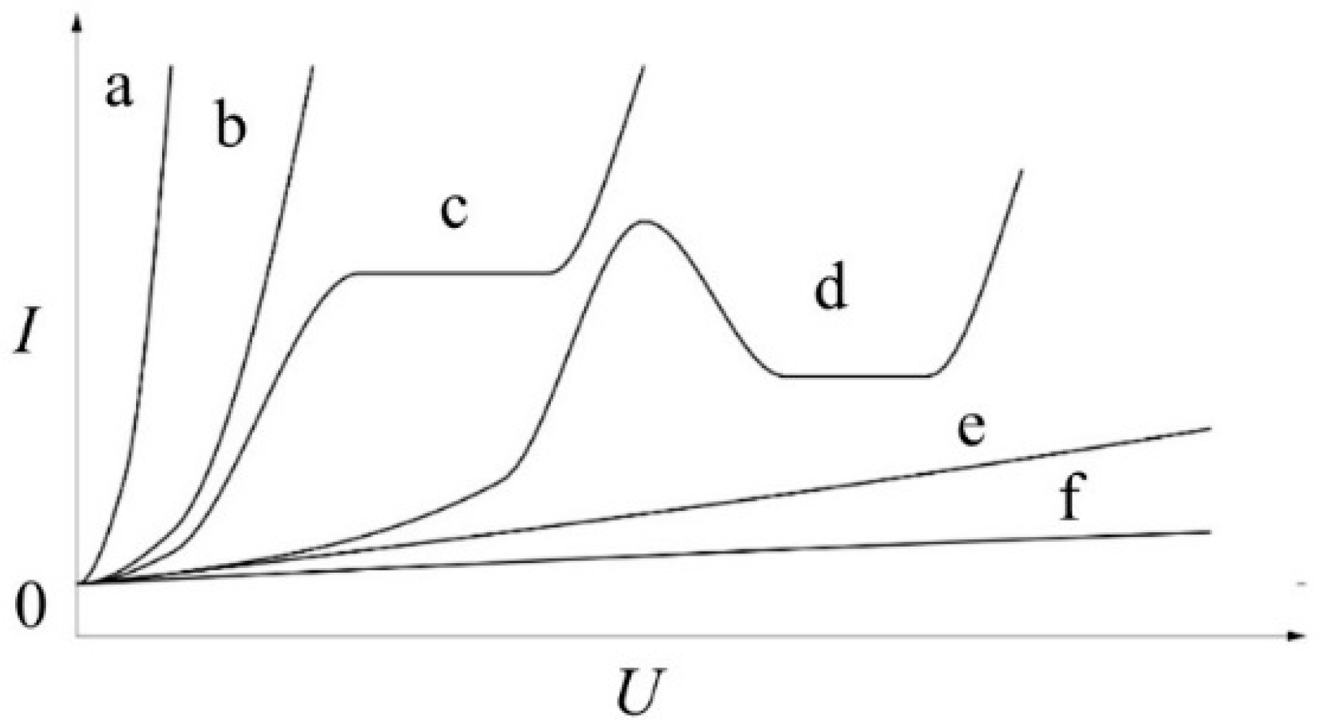
It is crucial for a technologically-relevant passive film formation that it does not exhibit electron conductivity, but rather ion conductivity [2]. This behavior is strongly dependent on the combination of electrode metal and electrolyte. Figure 1 summarizes the possible current density-potential behavior of an anodically polarized electrode in an electrolyte.
Only the passivating and, with some limitations, the complex behavior with a passive and a transpassive region are suitable for formation of reaction layers, which are appropriate for PEO initiation. A general overview over the chemical reactions that proceed during the growth of oxide e.g., hydroxide is given in Table 2.
The formation of the ion-conductive oxide layer results in significant electric resistance. In a current-controlled, galvanostatic process, it is characterized by a steep increase in the cell voltage within the first few seconds. Increasing electric field strengths are necessary to realize a further current flow and further oxide growth.
The rise in the anodic potential over the electrolyte/oxide/electrode system leads to the partial formation of a gas film around the electrode. This film consists of oxygen, arising from the electrochemical, or in later process states with high local energy input, thermal decomposition or vaporization of water. Additionally, the formed film further increases the electric resistance in the system electrolyte/gas/oxide/electrode. Thus, perpetuation of the current flow requires an increase of the potential until the strength of the electric field in the aforementioned system reaches a critical value, and the breakdown occurs. All this typically happens within the first minute of the process [17].
The breakdown of the system is mainly affected by the substrate material and the electrolyte composition, while it is independent of the current density, temperature, surface roughness, electrolyte movement, and the history of the system [51,52].
By injection of electrons at the electrolyte/gas interface, which acts as a quasi-cathode (equipotential area of the electric field), a discharge channel evolves and penetrates the oxide layer. Within the discharge channel, thermally-activated ions originating from the substrate metal are ejected and move away from the substrate, due to the migration in the electric field, while oxygen ions move towards the substrate. The oxide is then formed in a reaction of the substrate ions and oxygen ions and is deposited in the boundary regions of the channel. The discharge channel is characterized by a local current flow of an order of magnitude several kiloamperes per square centimeter under a high electric field, which results in enormous energy density. Thus, temperatures of several thousand Kelvin may occur locally. At the beginning of the discharge event, the breakdowns are concentrated on those surface regions with the highest electric field strength. Small, discrete micro-discharges are visible. In a galvanostatic process, the steep rise of the cell voltage gives way to a substantially less-pronounced increase or even slight decrease of the voltage. During the evolution of the process, the discharges become larger, while fewer discrete breakdown events are visible. Therefore, the energy within the discharges increases. This leads to a series of consequences: (1) The formation of high-temperature crystalline phases is promoted (e.g., α-alumina). This does not only imply the direct formation of these phases, but also the phase transformation of already-formed oxide in later process stages. (2) The direct vicinity of the discharge channel is heated. Since the breakdown voltage of the electrolyte/gas/oxide/electrode system decreases with increasing temperature, the initiation of a new discharge in the vicinity of a former discharge is promoted. However, no negative effect on the electrode metal occurs, since the thermal influences of the discharge events are limited to small volumes. The substrate usually does not suffer significant heating. (3) Re-melting of the oxide occurs. Since the dissipation of heat towards the electrolyte is generally higher than that towards the substrate, near-substrate regions of the coatings can be rather loose morphology in this region. (4) Large discharges can destroy the formed oxide coating. The occurrence of such detrimental discharges is dependent on the process parameters. It can take place several minutes to hours after the initiation of the first discharges and should be avoided. In a galvanostatic process, the cell voltage generally continues to increase at a relatively low rate, but it usually drops instantaneously with the occurrence of large and deteriorating discharge. The time on which this stage of the process is reached is strongly dependent on the process parameters. It is advisable to choose process time and parameters so that this critical stage is avoided [53,54].
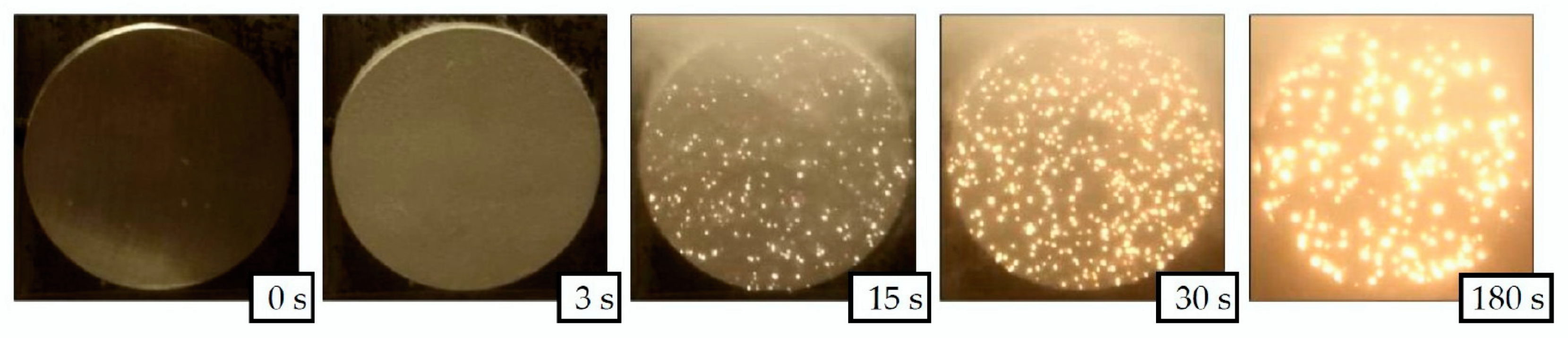
An example of the discharges evolution on a sample of the magnesium alloy AZ31 during the PEO in an alkaline silicate electrolyte is given in Figure 2. The brighter regions reflect the discharge action with brightness as a measure for the discharge intensity. The characteristic growth of discharges and the decrease of their number are observable in Figure 2 as well.
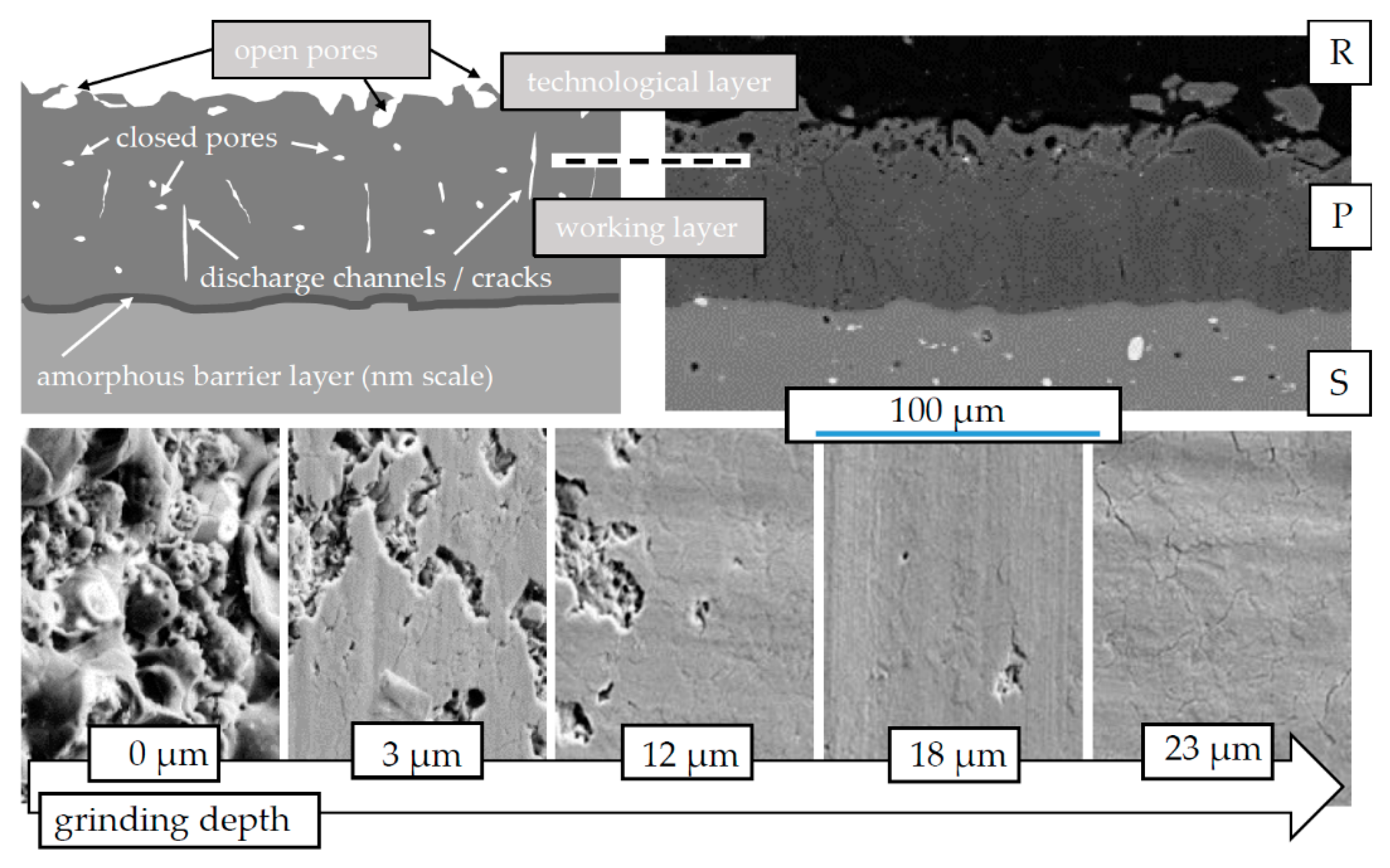
The three-layered structure of PEO coatings which typically occurs is shown schematically in Figure 10. The oxide coating is comprised of a nanometer-thin and, according to the described model, nearly defect-free (amorphous) barrier layer at the oxide/substrate interface [55,56], a rather compact working layer, and a loose outer layer, the so-called technological layer [18,19]. The thickness of the compact and the technological layer can stretch from a few microns to several hundred microns, depending on the conditions under which the PEO process is performed. Hence, the entire process is controlled by the electrical field and takes place under high electric potentials, and the PEO shows a very good throwing power which results in a homogenous layer thickness distribution, even on working pieces with complex geometry.
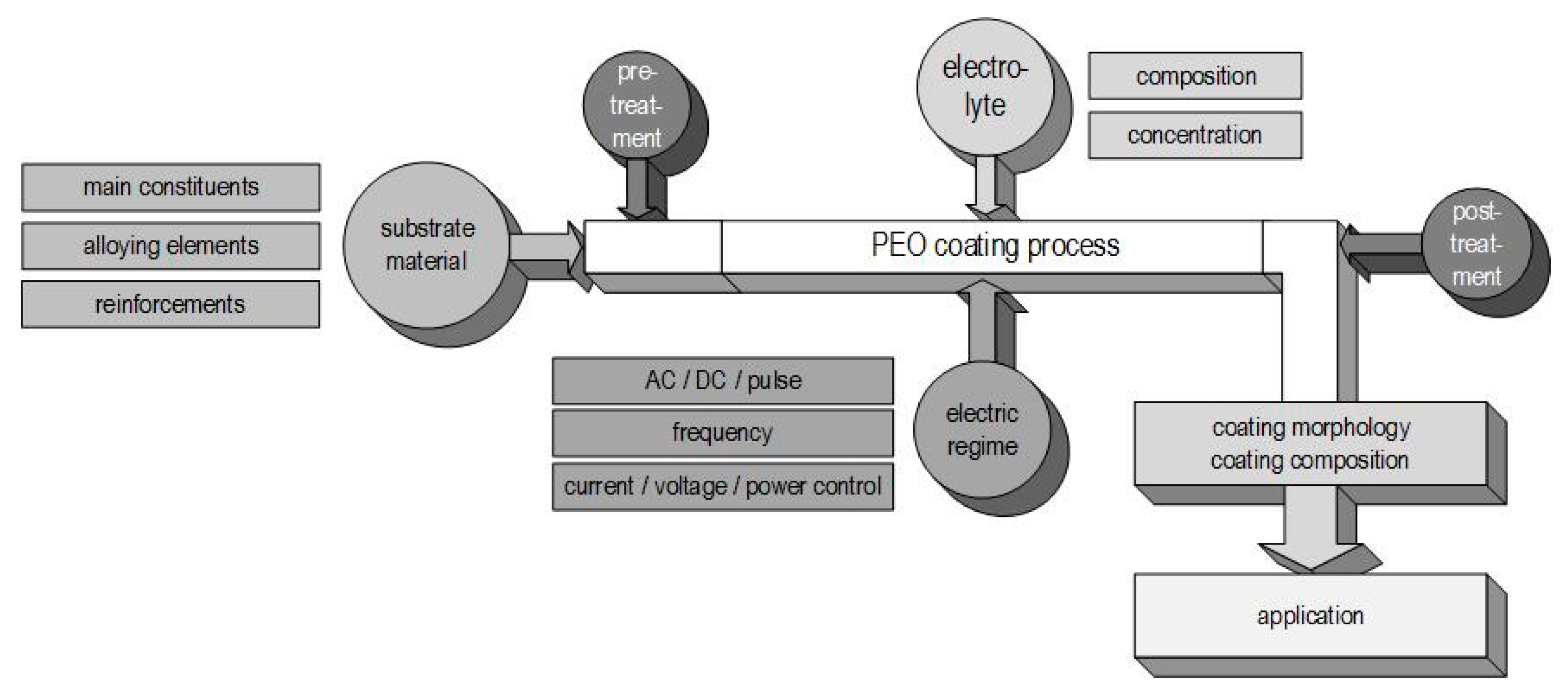
In the following, the different dependencies of the PEO process, primarily the substrate composition, the electrolyte used, the applied electrical regime, as well as their interaction with each other are discussed. Based on this, the formation and the technological properties of the resulting PEO layers are discussed and selected current application options are presented. Figure 3 summarizes the order of the focal points in this review using a schematic representation of the process steps during the plasma electrolytic oxidation.
3. Process Parameters and Coating Properties
3.1. Substrate
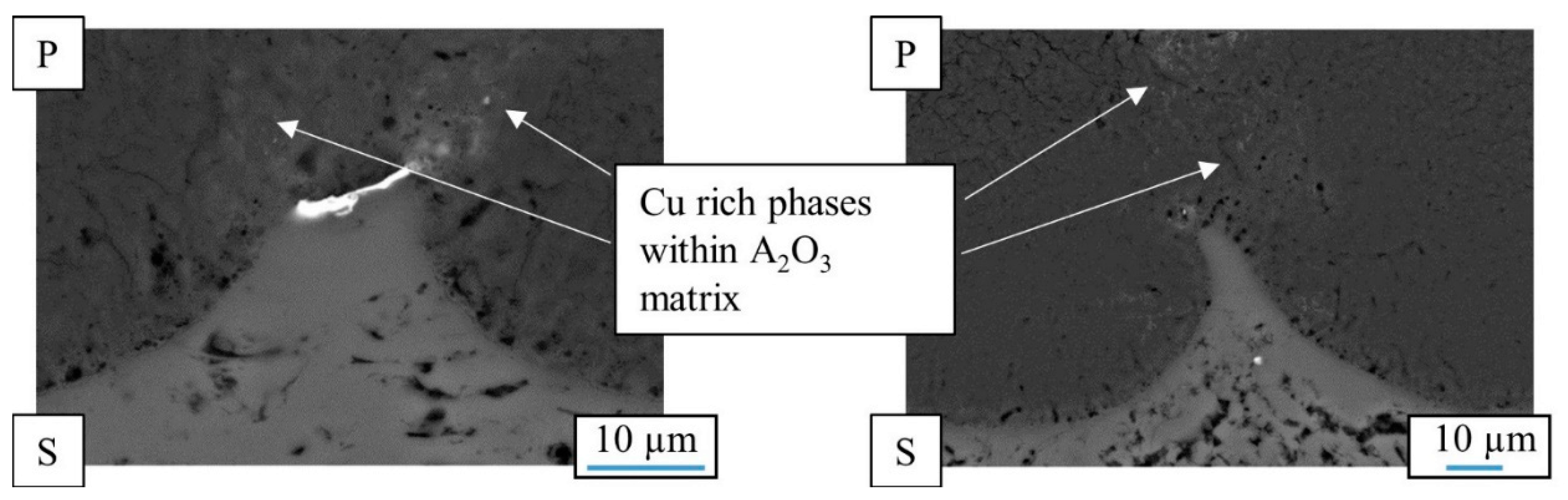
Plasma electrolytic oxidation in common low concentration aqueous electrolytes is at its core a conversion coating process. Hence, the nature of the oxide strongly depends on the substrate composition. The metal ions participating in the electrochemical reactions during the PEO process (Table 1) are determined by the treated material. Generally, oxides of the substrate metal are the main constituents of the coatings. The substrate conversion naturally includes alloying elements and precipitates in the metal as well as reinforcement phases in case of metal matrix composites. For aluminum, this is shown in Figure 4 and Figure 5. Figure 4 shows a scanning electron microscopy (SEM) picture of the oxide/substrate interface in the cross section of an oxide coating, produced by PEO in an alkaline silicate electrolyte on thermally-sprayed aluminum comprised of copper particles in BSE-mode (element contrast).
The bright fraction in the image represents a copper particle in the substrate. In the oxide above, the copper is obviously incorporated. It is also noticeable that the copper particle obstructs the conversion of the substrate, as in the surroundings, more of the substrate material has been consumed by the conversion coating process. Figure 5 shows a cross section of an oxide coating produced on an aluminum matrix composite (AMC) reinforced with silicon carbide or aluminum oxide particles.
It is obvious that the presence of SiC in the aluminum matrix leads to an increased number of flaws in the oxide, which are correlated to gas evolution at the electrically conductive particles. Remains of the particles, which are also partly converted, can be found in the pores of the coatings. However, under the high over-potential, the conversion of the silicon carbide particles takes place, presumably under gas evolution. This also results in a lower coating thickness, since the current efficiency is deteriorated by the evolution of gas. Unlike the presence of SiC, the presence of electrically non-conductive Al2O3 particles within the substrate does not affect the morphology or mechanical properties of the resulting PEO layer [57].
For aluminum in general, the existence of alloying elements like zinc, copper, or magnesium is likely to impede the transition from the metastable γ-phase to the high-temperature α-phase [58,59]. In addition, the alloying elements significantly influence the oxide phase distribution within the PEO layer [18]. Meanwhile, for magnesium alloys, the achievable coating thickness grows with an increasing content of aluminum or rare earths [55].
However, the coating composition and morphology are, not only influenced by the substrate material, but can also be altered by the incorporation of electrolyte constituents, as will be shown in the following section.
3.2. Electrolyte
Section 2 includes a classification of electrolyte components with regard to their passivating or dissolving behavior towards the substrate. Nevertheless, other classifications are possible. With regard to the incorporation of foreign compounds into the oxide coating, electrolytes are classified as follows: (1) electrolytes leading only to oxygen incorporation, (2) electrolytes leading to the incorporation of foreign compounds by anions, (3) electrolytes leading to the incorporation of foreign compounds by cations, and (4) electrolytes containing macroscopic particles, which are incorporated into the oxide by cataphoretic processes [17].
Common salts for the PEO of aluminum, magnesium, titanium, and their alloys in alkaline media are, amongst others, silicates, phosphates, aluminates, fluorides, borates, and stannates. Especially for the PEO of magnesium and its alloys, acidic or pH-neutral electrolyte compositions are used instead of alkaline electrolytes, e.g., fluoric acid, phosphoric acid, and/or boric acid in combination with organic additives, c.f. [60,61]. By incorporating elements provided by the electrolyte, the composition of the oxide can be altered substantially.
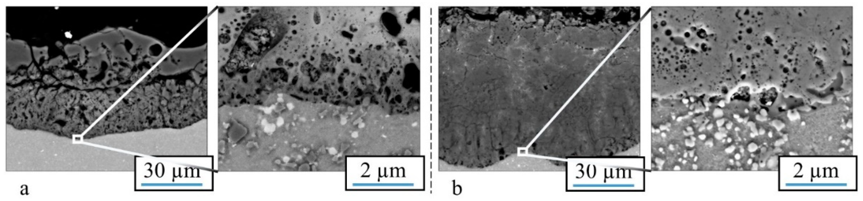
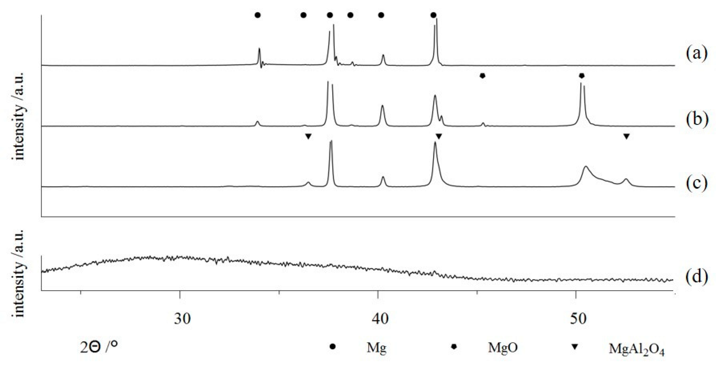
Some examples are shown in Figure 6, which contains x-ray diffractograms of uncoated Mg-AZ31 (a) as well as samples of the same material, which were treated by PEO within different alkaline media (b–d). The use of a low concentration phosphate electrolyte leads to the formation of a magnesia layer by substrate conversion. On the other side, highly concentrated solutions allow for the incorporation of electrolyte constituents into the resulting layer. In this way, PEO layers are formed in aluminate-rich solutions, which contain high proportions of crystalline MgAl2O4 spinels (6c) [21]. By using silicate-rich electrolytes, it is even possible to completely replace MgO in the PEO layer and to produce coatings, consisting of amorphous Mg / Si mixed oxides (6d), e.g., [20]. Since aluminum- or silicon-containing mixed oxides are usually superior over magnesia or titania in regards to their hardness and chemical resistivity, this approach is relevant for the PEO of magnesium and titanium alloys. Therefore, the method is converted from a conversion process to a mixed form of conversion and deposition. Another prominent example of the incorporation of electrolyte constituents into the oxide coatings is the formation of hydroxyapatite-containing PEO coatings on titanium from calcium- and phosphorus-containing electrolytes, c.f. [43,44]. Additionally, the coloring of working pieces by PEO for decorative or optical applications (e.g., blackened by use of vanadate ions) is already in practical use, c.f. [34,36].
For the PEO of aluminum, the widely-used silicate components lead to the incorporation of large amounts of silicon oxides or alumina-silica-mixed-phases (e.g., mullite), have a passivating effect on the aluminum substrate, while also not dissolving the formed alumina. This generally increases the achievable coating thickness and results in a compact morphology of the coatings. In contrast, the dissolution of alumina in strongly alkaline solutions [62,63] allow for an adjustment of the coating growth through the addition of hydroxide to the electrolyte [4]. However, recent investigations indicate that this mechanism mainly affects the amorphous alumina phases, c.f. [18].
3.3. Electric Regime
The electric regime during PEO can be determined by the control parameter (current density or cell voltage), the type of the supplied parameter (direct, alternating, pulse current/voltage), and the definition of the regime (frequency, breaks, limits etc.). Under direct current or voltage, the discharge events become ever more intense during the progression of the process. This includes large discharges with long life periods, which can have a deteriorating effect on both, the formed oxide and the substrate and thus lead to irreparable defects. This behavior results from excessive energy transfer and heat release. Therefore, pulse or alternating current or voltage regimes are used to limit the effect of the strong discharges and to facilitate the formation of thick oxide coatings up to a few hundred microns. Thus, the PEO process can be prolonged, the number of defects in the coatings decreased, and the formation of a thick technological layer on top of the coating is impeded. In the following, the effects of a pulsed regime and of an alternating regime shall be discussed.
In a pulse regime, the control parameter (current or voltage) is regularly set to a low value, typically to zero. During the formation of the barrier layer at the beginning of the process (the pre-spark stage), this only affects the process substantially, if the substrate material or the oxide are dissolved by the electrolyte.
The break in current flow regime gives time for chemical dissolution and can lead to a slower growth of the barrier oxide. In most cases, the barrier layer growth accelerates, since the break allows for the compensation of potential concentration gradients. Furthermore, the repeated steep rise of the control parameter results in a significant mass/charge transfer towards the substrate. After formation of the barrier layer, the system behaves like a capacitor. This includes that current flow occurs only above of a certain potential threshold. At each rising edge of the pulse, collision ionization is likely to occur and implies that the initiation of short, but intense discharge events are favored, as opposed to those favored in a direct current or voltage regime. At the falling edge of the pulse, the current flow is interrupted, and thus the length of the discharge periods are limited. Using this strategy, the PEO process can be performed for a longer duration without the development of large and deteriorating discharges. The utilization of an alternating regime likewise limits the life period of discharges. In addition, the cathodic half period of an alternating regime can lead to a partial electrochemical reduction of the oxide. Thus, the formation of a barrier layer sufficient for discharge initiation at the beginning of the PEO process will be prolonged. During the PEO process, discharge can also occur in the cathodic branch of the electric regime. This discharge is usually less intense than the discharge in the anodic branch. A lower amount of energy is introduced into the coating. However, the cathodic discharge is also prone to heat up the oxide locally, and are thus, likely to result in a reduction of the field strength necessary for the breakdown in the following anodic branch [54].
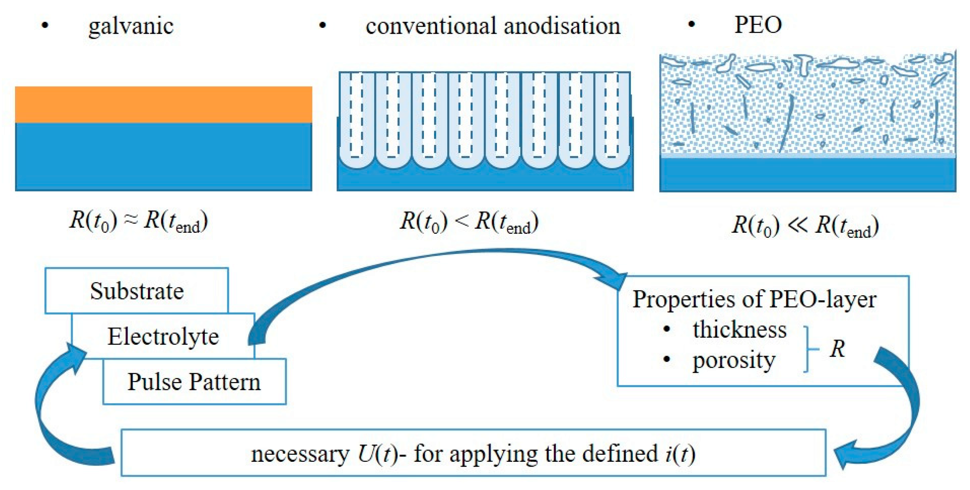
In general, the interactions of the substrate/electrolyte-combination with the electrical regime are complex and still a subject of research. A promising approach to gain experimental access to the relationships is the analysis of the electrical process data. Since, in contrast to other electrolytic surface treatment methods, PEO results in the formation of high-ohmic layers, these affect, above all in the case of current-controlled regimes, to what extent the pre-defined electrical pulse is mapped correctly in the experimental setup. Figure 7 shows a schematic representation of these relationships. Figure 8 illustrates them using the example of PEO of Mg-AZ31 samples with identical experimental parameters using different electrolytes.
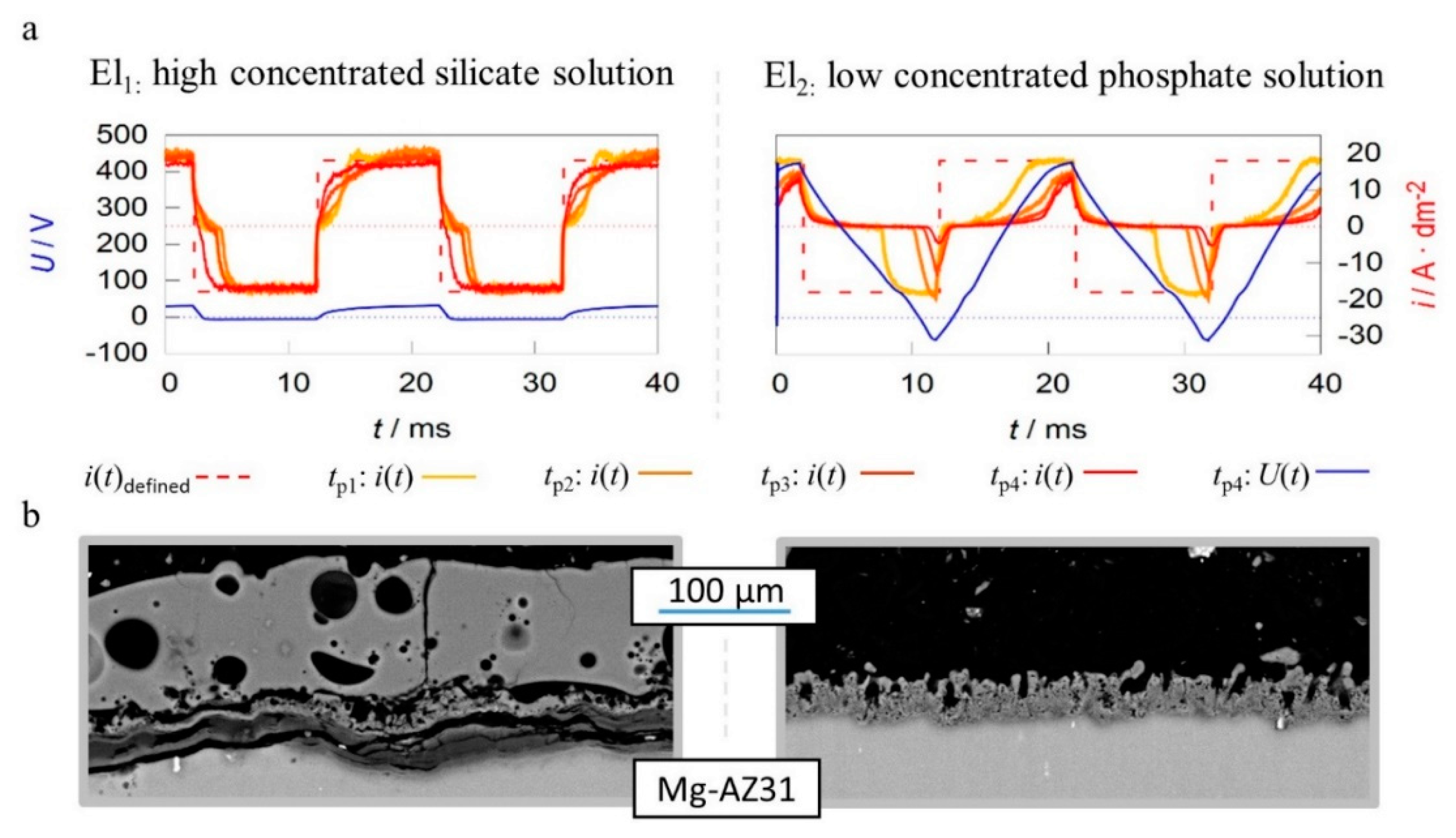
The working media used are designed for focused incorporation of electrolyte constituents into the coating (El1) and PEO layer formation by substrate conversion (El2). The current time characteristics measured during the process within the high concentration silicate solution show that the predefined symmetric rectangular current pattern is transmitted largely correctly to the system under investigation. Furthermore, the remaining deviations between predefined and measured pulses are decreasing with progression of the process time. In contrast to the effects described above, the experiment within the low concentration phosphate electrolyte shows a significant delay in the current flow after polarity reversal in both, the cathodic and anodic partial period. The delays even increase during the process. Additionally, the experiments in electrolyte 2 result in much higher voltages over the entire treatment time. This is exemplified by the voltage pattern after 20 min and leads to a higher consumption of electrical energy.
Therefore, one might assume that the experiment in electrolyte 1 had the more desirable process characteristics. However, consideration of the micrographs displayed in Figure 8b show that, despite a significantly increased layer thickness, an insufficient layer adhesion was achieved within electrolyte 1. Conversely, the coating formed in electrolyte 2 shows a good substrate bonding. Thus, the more pronounced delay of the current flow with increasing process time is not an error in the control of the behavior of the rectifier but belongs to the PEO process characteristics. A good adhesive layer of ceramic leads to an increasing electrical resistance at the substrate/electrolyte interface, which indicates that the current flow only starts after the rectifier has readjusted to higher process voltages. If the layers produced adhere poorly or worse with increasing treatment time, this mechanism is suppressed.
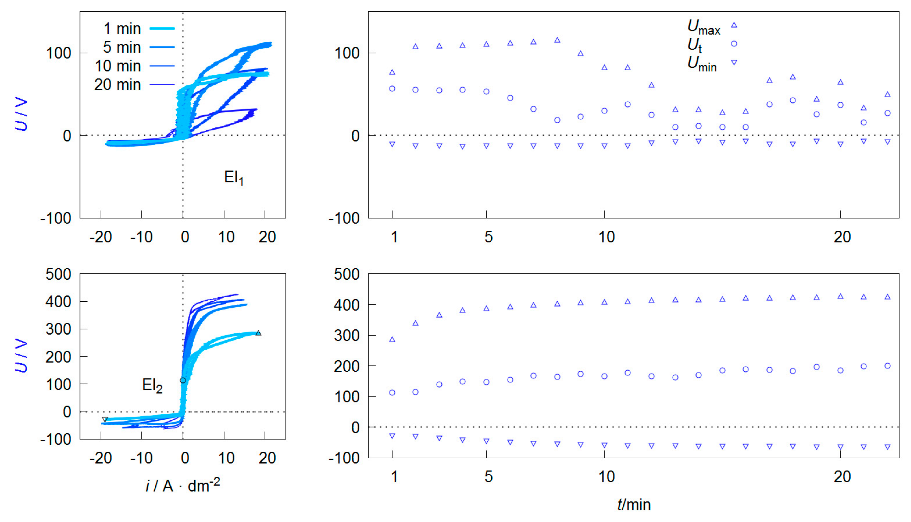
This behavior is mentioned at this point in discussion because, in addition to the layer state, the ignition voltage for discharge initiation during the PEO is also influenced by the electrolyte composition. However, the electrolyte resistance (or electrolyte conductivity) is negligible in most cases [51]. The depiction of the electrical process variables in relation to each other allows further conclusions to be drawn about the underlying process characteristics. Figure 9 represents the process data shown in Figure 8 as voltage current curves (VCC), as well as the course of specific voltage values over the treatment time.
Depending on the form of the representation, these curves are also referred to as current-voltage curves or characteristics or more generally as oscillograms. The value of the maximum Umax and minimum Umin voltage during one pulse cycle can be easily extracted from such a diagram. Furthermore it is possible to see that the downward branch of the anodic period shows a characteristic point at which the current flow stops while the voltage is still above the coordinate origin. This behavior can be observed at the process data of PEO on aluminum under various conditions, shown in several publications [64,65,66,67,68]. Within studies by Suminow et al. the value is called threshold voltage [1,2]. Duan et al. describes the polarization level below, when the charge carrier flow comes to a standstill as a critical conductive voltage [69]. Both research groups investigate the course of this voltage in dependence of the treatment time and assume that the value is proportional to the electrical isolation properties of the PEO layer after collapse of the plasma electrolytic discharges. Therefore, an increasing Ut indicates layer thickness growth and/or a decrease in the defect density within the layer. Insofar that this is correct, the evaluation of Ut allows, with respect to the anti-corrosive properties of the resulting PEO layers, the determination of optimal treatment times. In addition, the workload for materialographic examinations are reduced, since Ut provides automatically accessible information about the layer morphology. In contrast to microstructure images, these relate not only to a selected two-dimensional area but to the PEO layer along the entire substrate geometry. Hence, the method would be interesting also for non-destructive quality control.
Another interesting peculiarity of the VCCs shown in Figure 9 is that the ascending and descending anodic branches are not congruent. This is in accordance with recent studies by Ragov et al., which deal in detail with the analysis of electrical process data of the PEO of aluminum. Accordingly, the so-called hysteresis effects only occur in pulse regimes with cathodic components. The different conductivities in the rising and falling region of the anodic partial pulse are attributed to cathode-induced changes (CIC). These among others are substantiated by the incorporation of cations in a thin reaction layer at the substrate layer/interface of the so-called active zone. The subsequent release of the cations at the beginning of the anodic pulse leads to a brief increase in the electrical conductivity of the system. It is assumed that the few nm thick active zone has a strongly disproportionate contribution to the total electrical resistance of the layer system [70,71,72].
This would limit the significance of the threshold voltage mentioned above. Provided that the results can be transferred to the PEO of magnesium, the more pronounced hysteresis effects in Figure 9 for electrolyte 1 can be explained by the fact that there are significantly more cations in the electrolyte and the cathodic partial pulses are mapped almost completely.
4. Protective Properties of PEO Coatings
An example of the morphology of a PEO coating on an aluminum alloy (AlMgSi1), produced in an alkaline silicate electrolyte under the usage of a rectangular bipolar-pulsed current, is displayed in Figure 10.
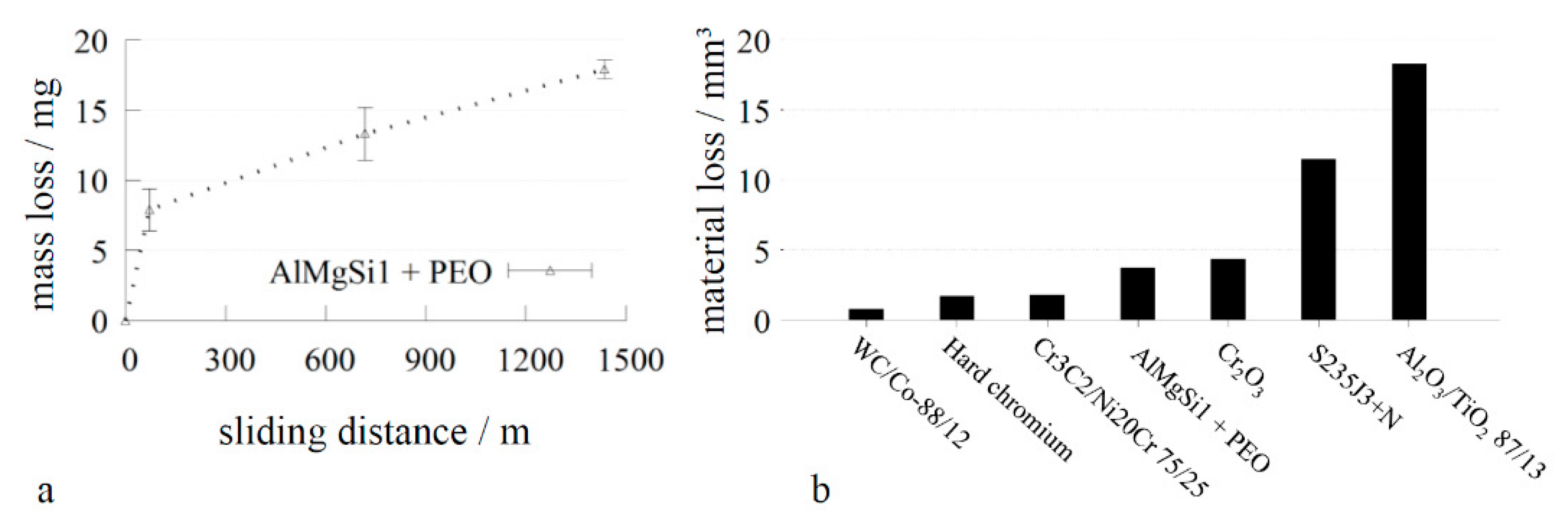
In the cross section of the coating, the rough and less compact technological layer at the top of the coatings, as well as the working layer, which is characterized by numerous micro-cracks and only small flaws, are visible. The top view of the successively grinded coating exhibits the typical surface morphology of PEO coatings, in which discharge channels are visible. With successive grinding, however, the number of visible flaws and defects is substantially reduced. The coating consists of aluminum oxide in different modifications (α-, γ-, δ- and amorphous) and exhibits a hardness of approx. 9.5 GPa on the Martens scale (HM0.05/30/30). As depicted in Figure 11a, the morphology is reflected by the wear behavior (rubber wheel test according to ASTM G65), in which a significant initial wear of the coating is registered, while the subsequent increase of the sliding distance leads only to a moderate increase of the mass loss of the samples. In order to optimize hte PEO layers for tribological applications, the technological layer is sometimes removed by an additional polishing step. For classification, Figure 11b shows the appropriate volume wear of the mentioned PEO coating in comparison to other state-of-the-art wear-resistant coatings.
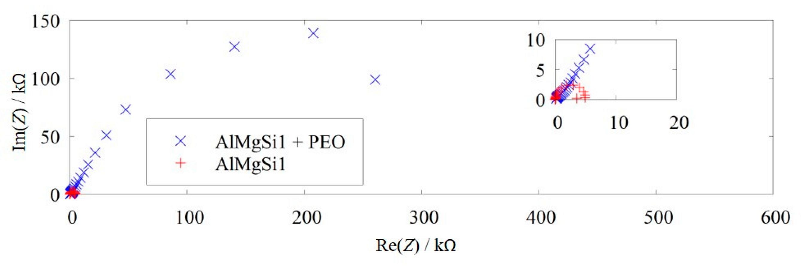
As can be seen, the PEO coating offers a wear resistance similar to materials, which are either much heavier, or the production or handling of which is unsanitary and/or harmful to the environment. Furthermore, the use of these alternative wear protection systems almost exclusively contains heavy materials with a high density. Additionally, the PEO coating provides reasonable corrosion protection. Figure 12 shows the impedance behavior of the PEO-coated AlMgSi1 alloy in comparison to the bare AlMgSi1 alloy in dilute, acidic sodium chloride solution.
The diameter of the characteristic semi-circle represents the resistance against charge-transfer between electrolyte and substrate. Hence, it is interpreted as an abstract measure for corrosion resistivity. For the PEO-coated surface, the charge transfer resistance is approx. 300 kΩ, while it equals 5 kΩ for a bare aluminum surface. Therefore, the resistance against the flow of current, which is correlated to corrosive attack, is increased by two orders of magnitude.
PEO coatings on magnesium and titanium materials exhibit a lower mechanical stability than those produced on aluminum alloys. This behavior is observed as the oxide phases obtained by substrate conversion like periclase (cubic MgO) or rutil and anastas (tetragonal TiO2 modifications) have a lower hardness than the aluminum oxide modifications. For this reason, highly-concentrated process media are often used for the PEO treatment of these materials in order to shift the phase composition of the layers produced in favor of more resistant compounds through the focused incorporation of electrolyte components (see Section 3.2). Furthermore, subprocesses, which are not yet entirely understood, during the layer formation lead to PEO coatings on Mg and Ti alloys, revealing a far less compact structure than shown in Figure 10 for Al materials. In the case of magnesium, toxic fluoride compounds are known as suitable electrolyte components to improve the morphology of the resulting layers [73,74]. In general, sealing by organic or inorganic polymers can be applied as a post treatment to fill open porous cavities [75,76]. Thus, a substrate attack by corrosive media can be limited, while the structure of the coating is mechanically supported.
5. Further Functional Characteristics and Applications
Based on its low density and high wear and corrosion resistivity, PEO-coated aluminum is widely used for quickly moving parts which face aggressive atmospheres. Figure 13 shows the rotor of a turbo molecular pump with a diameter of approximately 15 cm (a) and a centering ring (b). The components are used to transport gases and for plasma etching processes, and they are working at rotation speeds of some 10,000 min−1 [77].
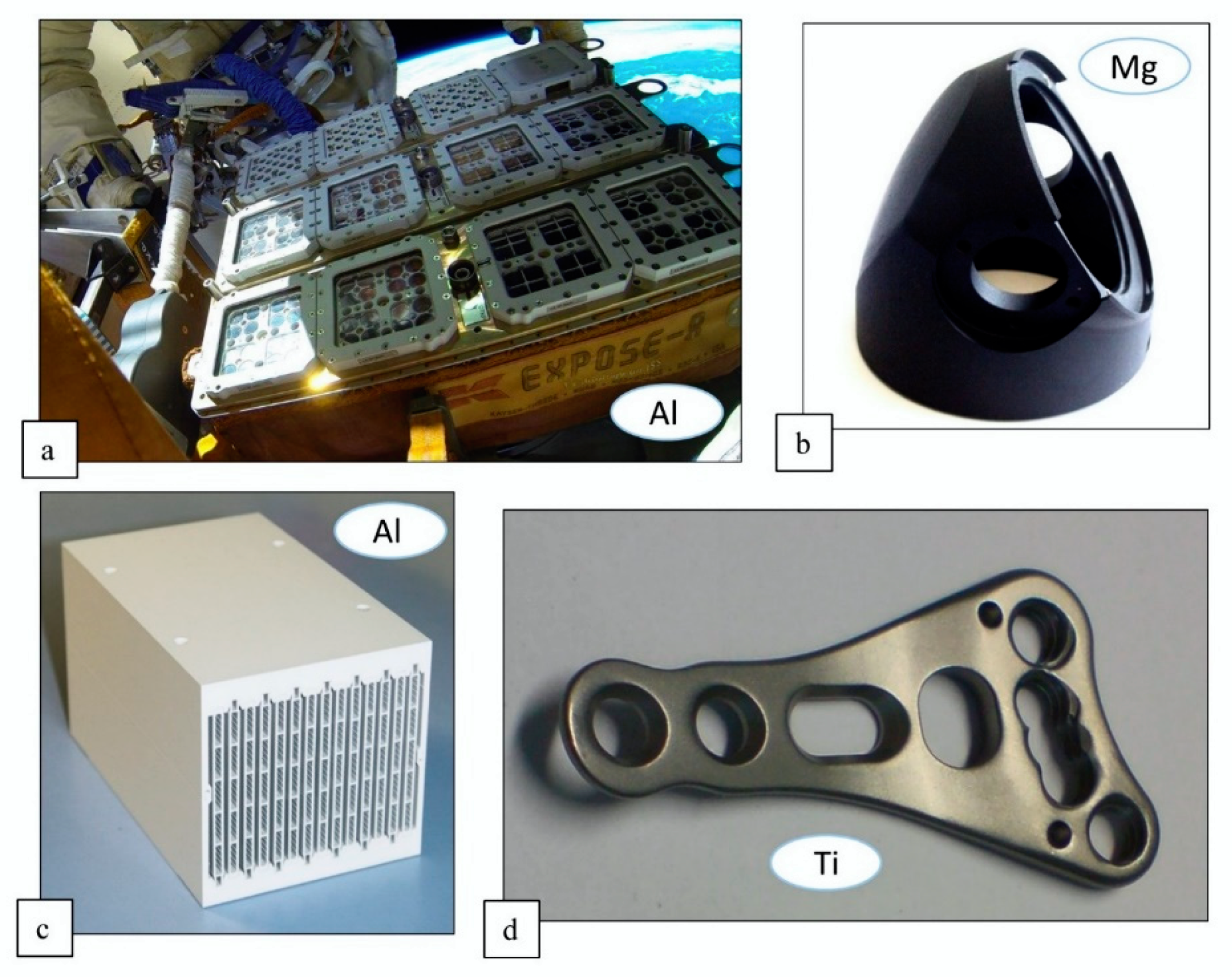
Furthermore, PEO-coated devices are interesting for space engineering applications: The layers have excellent thermocycling resistance, due to their good substrate binding. Therefore, they withstand tremendous temperature fluctuations, which occur in space as a result of changing irradiation and shading, without the flaking of the PEO layers. An example of this is shown in Figure 14a. The photo shows a close-up of the EXPOSE experiment on the international space station ISS.
The experimental setup is in use for astrobiological experiments. The covers are coated with PEO layers, which provide the necessary corrosion protection and, through their very low tendency towards outgassing, additionally prevent contamination of the experimental atmosphere. Low outgassing is also important to prevent the degradation of optical devices. The die-cast component depicted in Figure 14b was additionally blackened during the PEO by use of adapted electrolytes. Therefore, the light absorption is improved and the stray light effects by reflection are reduced to a minimum. Additionally, such surfaces show a convenient ratio of solar absorptance and emittance close to one, which is desirable for passive thermal control in space. Figure 14c shows a plasma-electrolytically-oxidized heat sink. The excellent throwing power of the PEO allows a uniform inner coating of the filigree channels [35].
The commercial name PCO®® stands for plasma chemical oxidation. Its different modifications shown in the Figure 14a–d have the suffixes 13-white, 12-black, 13-white and 22-bio, which represent the atomic number of the substrate dominating element and functionality.
Another field of application of PEO is medical engineering, such as the production of osseo-integrative coatings for dental and orthopedic implants. Implant materials have to meet certain requirements like biocompatibility (hemocopatibility, cytocompatibility), non-toxicity, chemical stability, and corrosion resistance. With a moderate density and a good specific strength, titanium is a material of choice for implants. Furthermore, titanium and its oxides are not bioactive. Thus, no chemical bonding of the titanium implant with bone tissue occurs, which is beneficial for temporary implants, e.g., for fracture treatment. Figure 14d shows a Ti-plate for osteosynthesis which was treated by PEO to increase the thickness of the native titania layer. This serves to avoid contact welding with the titanium screws used for fixation and to allow unimpeded implant removal.
While, non-bioactivity of titania is beneficial for temporary implants, e.g., for fracture treatment, it is disadvantageous for permanent implants. Therefore, the surface of the implant has to be modified with bioactive coatings. The formation of a hydroxyapatite (Ca10(PO4)6(OH)2) coatings on titanium surfaces has been proven to facilitate osseointegration of implants without detrimental effects on the body. Generally, there are two ways to utilize PEO for the production of hydroxyapatite coatings: (1) Formation of a Ca- and P-containing titanium oxide coating by PEO and the subsequent hydrothermal treatment of the resulting coating to form hydroxyapatite (two-step process), or (2) formation of a hydroxyapatite-containing coating by PEO (one-step process). The most important factors for the bonding between implant and tissue are the composition of the coating, as well as its surface morphology and roughness [43,44].
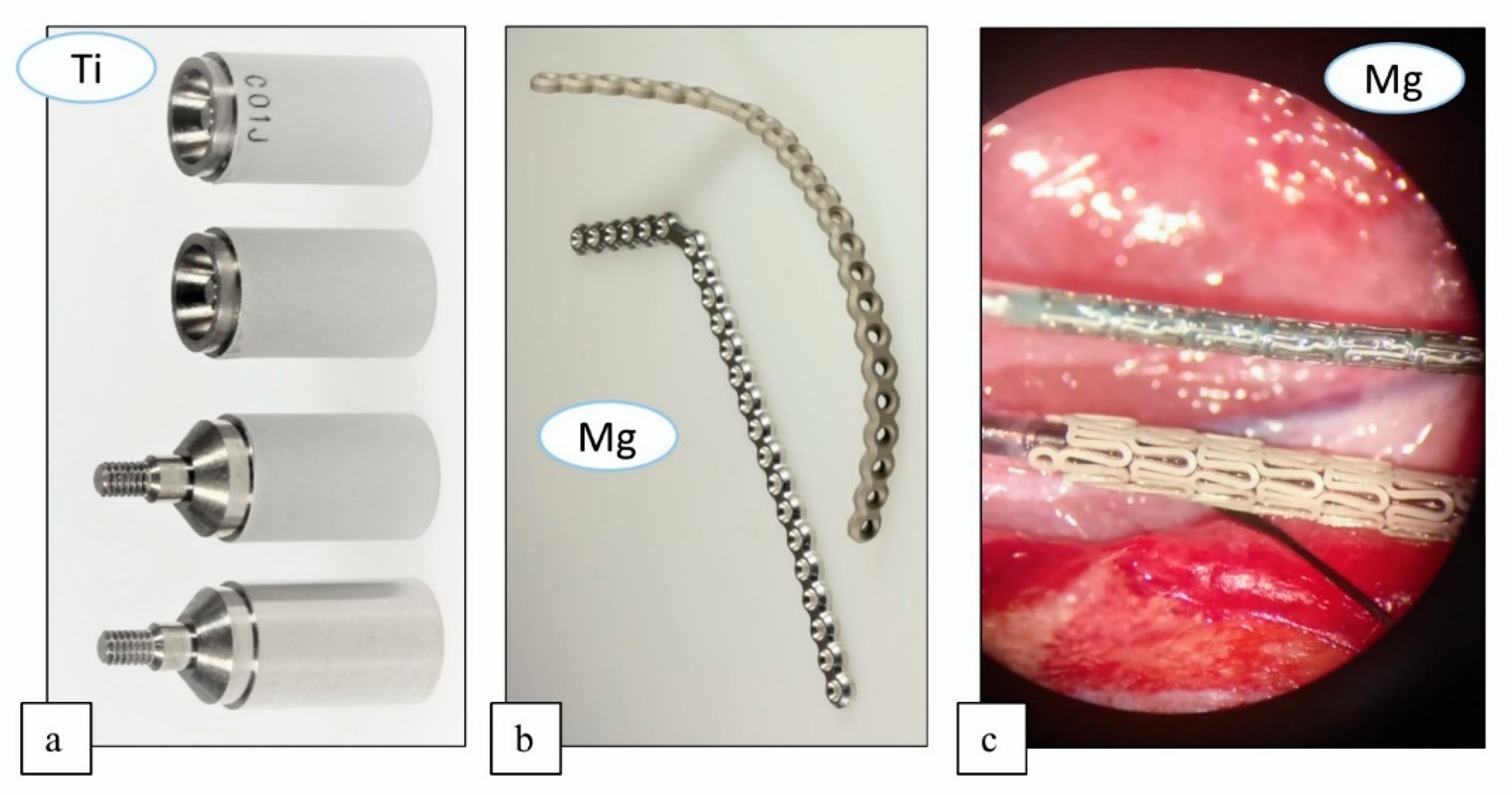
The scan body locators, depicted in Figure 15a, are used in the dental implant technology to manufacture perfectly-fitting superstructures. Such prostheses are placed on posts anchored in the jaw and can support entire rows of teeth. The locators are deployed on laboratory analogs of impressions of the oral cavity and screwed in at the places where the implanted posts will later sit. The resulting geometry is then digitized using a three-dimensional (3D) laser scanner. The PEO coating on the locators (commercial name ScanOX®®) minimizes the optical reflection of the laser light and thus increases the quality of the data generated. Finally, the generated data are used for milling the superstructure, including perfectly positioned recesses for the jaw posts. Figure 15b,c shows a plate for osteosynthesis of bone fractures and a stent for treatment of coronal issues. The devices are made from magnesium, and they usually degrade within body tissue in a time-span of 12–24 months. The PEO coating (commercial name KERMASORB®®) regulates or delays this process so that the components remain stable in the first critical months [42].
6. Conclusions
Plasma electrolytic oxidation enables unique coating results due to its special process characteristics. Thanks to active research and development activities by scientific institutions and innovative companies, the selection of the treatable substrates as well as the composition and morphology of the layers that can be achieved have been expanded within wide limits. This allows for an increasing number of novel applications for the process in high technology fields. Recent advances in the field of process data analysis increasingly allow experimental access to the sub-mechanisms that occur during the PEO, and also form the basis for integrating the method into an increasingly digitized industry. Therefore, further progress in the field of plasma electrolytic oxidation can be expected in the next few years.
Funding
The financial support of this work by the Deutsche Forschungsgemeinschaft (DFG) is gratefully acknowledged (project number La-1274/55-1).
Acknowledgments
The support of Aalberts Surface Treatment GmbH, INNOVENT e.V. and Meotec GmbH by providing photographs of their products is grateful acknowledged. The support of Lisa-Marie Rymer and Morgan Uland is gratefully acknowledged as well.
Conflicts of Interest
The authors declare no conflict of interest.
References
- Sluginov, N.P. On luminous phenomen, observed in liquids during electrolysis. J. Russ. Phys. Chem. Soc. 1880, 12, 193–203. [Google Scholar]
- Güntherschulze, A.; Betz, H. Electrolytic Capacitors, 2nd ed.; Cram: Berlin, Germany, 1952. [Google Scholar]
- Brown, S.D.; Kuna, K.J. Anodic Spark Deposition from Aqueous Soulutions of NaAlO2 and Na2SiO3. J. Am. Ceram. Soc. 1971, 54, 385–390. [Google Scholar] [CrossRef]
- Yerokhin, A.L.; Voevodin, A.A.; Lyubimov, V.V.; Zabinski, J.; Donley, M. Plasma electrolytic fabrication of oxide ceramic surface layers for tribotechnical purposes on aluminium alloys. Surf. Coat. Technol. 1998, 110, 140–146. [Google Scholar] [CrossRef]
- Kurze, P. Production, Characterization and Application of Al2O3 Layers, Especially on Aluminium and Iron Materials, Dissertation. Ph.D. Thesis, TU Chemnitz, Chemnitz, Germany, 1981. [Google Scholar]
- Krysmann, W.; Kurze, P.; Dittrich, K.-H.; Schneider, H.G. Process Characteristics and Parameters of Anodic Oxidation. Cryst. Res. Technol. 1984, 19, 973–979. [Google Scholar] [CrossRef]
- Fattah-Alhosseini, A.; Molaei, M.; Kazem, B.; Babaei, K. Influence of Electrolyte Composition and Voltage on the Microstructure and Growth Mechanism of Plasma Electrolytic Oxidation (PEO) Coatings on Tantalum- A Review. Anal. Bioanal. Electrochem. 2020, 12, 517–535. [Google Scholar] [CrossRef]
- Fattah-Alhosseini, A.; Babaei, K.; Molaei, M. Plasma electrolytic oxidation (PEO) treatment of zinc and its alloys. Surf. Interfaces 2020, 18, 100441. [Google Scholar] [CrossRef]
- Krit, B.L.; Ludin, V.B.; Morozova, N.V.; Apelfeld, A.V. Microarc Oxidation of Carbon-Graphite Materials (Review). Surf. Eng. Appl. Electrochem. 2018, 54, 227–246. [Google Scholar] [CrossRef]
- Lu, X.; Mohedano, M.; Blawert, C.; Matykina, E.; Arrabal, R.; Kainer, K.U.; Zheludkevich, M.L. Plasma electrolytic oxidation coatings with particle additions—A review. Surf. Coat. Technol. 2016, 307, 1165–1182. [Google Scholar] [CrossRef]
- Fattah-Alhosseini, A.; Chaharmahali, R.; Babaei, K. Effect of particles addition to solution of plasma electrolytic oxidation (PEO) on the properties of PEO coatings formed on magnesium and its alloys. J. Magnes. Alloys 2020. In Press. [Google Scholar] [CrossRef]
- SharifiI, H.; Aliofkhazraei, M.; Darband, G.B.; Shrestha, S. A review on adhesion strength of PEO coatings by scratch test method. Surf. Rev. Lett. 2018, 25, 3. [Google Scholar] [CrossRef]
- Gnedenkov, S.V.; Sinebryukhov, S.L.; Sergienko, V. Composite PEO-Coatings as Defence Against Corrosion and Wear: A Review. Corros. Sci. Tech. 2019, 18, 212–219. [Google Scholar] [CrossRef]
- Clyne, T.W.; Troughton, S.C. A review of recent work on discharge characteristics during plasma electrolytic oxidation of various metals. Int. Mater. Rev. 2018, 64, 127–162. [Google Scholar] [CrossRef] [Green Version]
- Tsai, D.S.; Chou, C.C. Review of the Soft Sparking Issues in Plasma Electrolytic Oxidation. Metals 2018, 8, 105. [Google Scholar] [CrossRef] [Green Version]
- Walsh, F.C.; Low, C.T.J.; Wood, R.J.K.; Stevens, K.; Archer, J.; Poeton, A.R.; Ryder, A. Plasma electrolytic oxidation (PEO) for production of anodised coatings on lightweight metal (Al, Mg, Ti) alloys. Trans. Inst. Met. Finish. 2009, 87, 122–135. [Google Scholar] [CrossRef]
- Yerokhin, A.L.; Nie, X.; Leyland, A.; Matthews, A.; Dowey, S.J. Plasma electrolysis for surface engineering. Surf. Coat. Technol. 1999, 122, 73–93. [Google Scholar] [CrossRef]
- Sieber, M.; Simchen, F.; Morgenstern, R.; Scharf, I.; Lampke, T. Plasma Electrolytic Oxidation of High-Strength Aluminium Alloys—Substrate Effect on Wear and Corrosion Performance. Metals 2018, 5, 365. [Google Scholar] [CrossRef] [Green Version]
- Sieber, M.; Mehner, T.; Dietrich, D.; Alisch, G.; Nickel, D.; Meyer, D.; Scharf, I.; Lampke, T. Wear-resistant coatings on aluminium produced by plasma anodising—A correlation of wear properties, microstructure, phase composition. Surf. Coat. Technol. 2014, 240, 96–102. [Google Scholar] [CrossRef]
- Simchen, F.; Rymer, L.M.; Sieber, M. Composition of highly concentrated silicate electrolytes and ultrasound influencing the plasma electrolytic oxidation of magnesium. IOP Conf. Ser. Mater. Sci. Eng. 2017, 181, 012040. [Google Scholar] [CrossRef] [Green Version]
- Sieber, M.; Simchen, F.; Scharf, I.; Lampke, T. Formation of a Spinel Coating on AZ31 Magnesium Alloy by Plasma Electrolytic Oxidation. J. Mater. Eng. Perform. 2016, 25, 1157–1162. [Google Scholar] [CrossRef]
- Yerokhin, A.; Leyland, A.; Matthews, A. Kinetic aspects of aluminium titanate layer formation on titanium alloys by plasma electrolytic oxidation. Appl. Surf. Sci. 2002, 200, 172–184. [Google Scholar] [CrossRef]
- Yerokhin, A.L.; Nie, X.; Leyland, A.; Matthews, A. Characterisation of oxide films produced by plasma electrolytic oxidation of a Ti–6Al–4V alloy. Surf. Coat. Technol. 2000, 130, 195–206. [Google Scholar] [CrossRef]
- Cheng, Y.; Zhu, Z.; Zhang, Q.; Zhuang, X.; Cheng, Y. Plasma electrolytic oxidation of brass. Surf. Coat. Technol. 2020, 385, 125366. [Google Scholar] [CrossRef]
- Malinovschi, V.; Marin, A.; Moga, S.; Negrea, D. Preparation and characterization of anticorrosive layers deposited by micro-arc oxidation on low carbon steel. Surf. Coat. Technol. 2014, 253, 194–198. [Google Scholar] [CrossRef]
- Pezzato, L.; Brunelli, K.; Dolcet, P.; Dabalà, M. Plasma electrolytic oxidation coating produced on 39NiCrMo3 steel. Surf. Coat. Technol. 2016, 307, 73–80. [Google Scholar] [CrossRef]
- Yang, W.; Li, Q.; Liu, W.; Liang, J.; Peng, Z.; Liu, B. Characterization and properties of plasma electrolytic oxidation coating on low carbon steel fabricated from aluminate electrolyte. Vacuum 2017, 144, 207–216. [Google Scholar] [CrossRef]
- Yang, W.; Peng, Z.; Liu, B.; Liu, W.; Liang, J. Influence of Silicate Concentration in Electrolyte on the Growth and Performance of Plasma Electrolytic Oxidation Coatings Prepared on Low Carbon Steel. J. Mater. Eng. Perform. 2018, 27, 2345–2353. [Google Scholar] [CrossRef]
- Ge, Y.; Wang, Y.; Cui, Y.; Zou, Y.; Guo, L.; Ouyang, J.; Jia, D.; Zhou, Y. Growth of plasma electrolytic oxidation coatings on Nb and corresponding corrosion resistance. Appl. Surf. Sci. 2019, 491, 526–534. [Google Scholar] [CrossRef]
- Quintero, D.; Gómez, M.A.; Araujo, W.S.; Echeverría, F.; Calderón, J.A. Influence of the electrical parameters of the anodizing PEO process on wear and corrosion resistance of niobium. Surf. Coat. Technol. 2019, 380, 125067. [Google Scholar] [CrossRef]
- He, S.; Ma, Y.; Ye, H.; Liu, X.; Dou, Z.; Xu, Q.; Wang, H.; Zhang, P. Ceramic oxide coating formed on beryllium by micro-arc oxidation. Corros. Sci. 2017, 122, 108–117. [Google Scholar] [CrossRef]
- Cheng, Y.; Zhang, Q.; Zhu, Z.; Tu, W.; Cheng, Y.; Skeldon, P. Potential and morphological transitions during bipolar plasma electrolytic oxidation of tantalum in silicate electrolyte. Ceram. Int. 2020, 46, 13385–13396. [Google Scholar] [CrossRef]
- Yao, Z.; Shen, Q.; Niu, A.; Hu, B.; Jiang, Z. Preparation of high emissivity and low absorbance thermal control coatings on Ti alloys by plasma electrolytic oxidation. Surf. Coat. Technol. 2014, 242, 146–151. [Google Scholar] [CrossRef]
- Wang, L.; Zhou, J.; Liang, J.; Chen, J. Thermal control coatings on magnesium alloys prepared by plasma electrolytic oxidation. Appl. Surf. Sci. 2013, 280, 151–155. [Google Scholar] [CrossRef]
- Available online: https://www.innovent-jena.de/ (accessed on 29 June 2020).
- Kurze, P.; Krysmann, W.; Schreckenbach, J.; Schwarz, T.; Rabending, K. Coloured ANOF Layers on Aluminium. Cryst. Res. Technol. 1987, 22, 53–58. [Google Scholar] [CrossRef]
- Wang, J.-M.; Tsai, D.-S.; Tsai, J.T.; Chou, C.-C. Coloring the aluminum alloy surface in plasma electrolytic oxidation with the green pigment colloid. Surf. Coat. Technol. 2017, 321, 164–170. [Google Scholar] [CrossRef]
- Wang, S.; Liu, P. The technology of preparing green coating by conducting micro-arc oxidation on AZ91D magnesium alloy. Pol. J. Chem. Technol. 2016, 18, 36–40. [Google Scholar] [CrossRef] [Green Version]
- Curran, J.A.; Kalkancı, H.; Magurova, Y.; Clyne, T.W. Mullite-rich plasma electrolytic oxide coatings for thermal barrier applications. Surf. Coat. Technol. 2007, 201, 8683–8687. [Google Scholar] [CrossRef]
- Cengiz, S.; Uzunoglu, A.; Stanciu, L.; Tarakci, M.; Gencer, Y. Direct fabrication of crystalline hydroxyapatite coating on zirconium by single-step plasma electrolytic oxidation process. Surf. Coat. Technol. 2016, 301, 74–79. [Google Scholar] [CrossRef]
- Antonio, R.F.; Rangel, C.E.; Mas, B.A.; Duek, E.A.R.; Cruz, N.C. Growth of hydroxyapatite coatings on tantalum by plasma electrolytic oxidation in a single step. Surf. Coat. Technol. 2019, 357, 698–705. [Google Scholar] [CrossRef]
- Available online: http://www.meotec.eu/home/ (accessed on 29 June 2020).
- Wang, Y.; Yu, H.; Chen, C.; Zhao, Z. Review of the biocompatibility of micro-arc oxidation coated titanium alloys. Mater. Des. 2015, 85, 640–652. [Google Scholar] [CrossRef]
- Rafieerad, A.R.; Ashra, M.R.; Mahmoodian, R.; Bushroa, A.R. Surface characterization and corrosion behavior of calcium phosphate-base composite layer on titanium and its alloys via plasma electrolytic oxidation: A review paper. Mater. Sci. Eng. C 2015, 85, 640–652. [Google Scholar] [CrossRef]
- Stojadinović, S.; Tadić, N.; Ćirić, A.; Vasilić, R. Photoluminescence properties of Eu3+ doped HfO2 coatings formed by plasma electrolytic oxidation of hafnium. Opt. Mater. 2018, 77, 19–24. [Google Scholar] [CrossRef]
- Stojadinovic, S.; Vasilić, R. Plasma electrolytic oxidation of hafnium. Int. J. Refract. Met. Hard Mater. 2017, 69, 153–157. [Google Scholar] [CrossRef]
- Wang, J.; Li, C.; Yao, Z.; Yang, M.; Wang, Y.; Xia, Q.; Jiang, Z. Preparation of Fenton-like coating catalyst on Q235 carbon steel by plasma electrolytic oxidation in silicate electrolyte. Surf. Coat. Technol. 2016, 307, 1315–1321. [Google Scholar] [CrossRef]
- Wang, J.; Yao, Z.; Yang, M.; Wang, Y.; Xia, Q.; Jiang, Z. A Fe3O4/FeAl2O4 composite coating via plasma electrolytic oxidation on Q235 carbon steel for Fenton-like degradation of phenol. Environ. Sci. Pollut. Res. Int. 2016, 23, 14927–14936. [Google Scholar] [CrossRef] [PubMed]
- Lohrengel, M.M. Thin anodic oxide layers on aluminium and other valve metals: High field regime. Mater. Sci. Eng. R. 1993, 11, 243–294. [Google Scholar] [CrossRef]
- Song, L.W.; Song, Y.W.; Shan, D.Y.; Zhu, D.Y.; Han, E.H. Product/metal ratio (PMR): A novel criterion for the evaluation of electrolytes on micro-arc oxidation (MAO) of Mg and its alloys. Sci. China Technol. Sci. 2011, 54, 2795–2801. [Google Scholar] [CrossRef]
- Simchen, F.; Sieber, M.; Lampke, T. Electrolyte influence on ignition of plasma electrolytic oxidation processes on light metals. Surf. Coat. Technol. 2017, 315, 205–213. [Google Scholar] [CrossRef]
- Ikonopisov, S. Theory of electrical breakdown during formation of barrier anodic films. Electrochem. Acta 1977, 22, 1077–1082. [Google Scholar] [CrossRef]
- Yerokhin, A.L.; Snizhko, L.O.; Gurevina, N.L.; Leyland, A.; Pilkington, A.; Matthews, A. Discharge characterization in plasma electrolytic oxidation of aluminium. J. Phys. D Appl. Phys. 2003, 36, 2110–2120. [Google Scholar] [CrossRef]
- Suminow, I.W.; Epelfeld, A.B.; Ljudin, W.B.; Krit, B.L.; Borisow, A.M. Micro Arc Oxidation; Ekomet: Moskow, Russia, 2005. [Google Scholar]
- Matykina, E.; Arrabal, A.; Skeldon, P.; Thompson, G.E. Investigation of the growth processes of coatings formed by AC plasma electrolytic oxidation of aluminium. Electrochem. Acta 2009, 54, 6767–6778. [Google Scholar] [CrossRef]
- Nie, X.; Meletis, E.I.; Jiang, J.C.; Leyland, A.; Yerokhin, A.L.; Matthews, A. Abrasive wear/corrosion properties and TEM analysis of Al2O3 coatings fabricated using plasma electrolysis. Surf. Coat. Technol. 2002, 149, 245–251. [Google Scholar] [CrossRef]
- Morgenstern, R.; Sieber, M.; Lampke, T. Plasma electrolytic oxidation of AMCs. IOP Conf. Ser. Mater. Sci. Eng. 2016, 118. [Google Scholar] [CrossRef] [Green Version]
- Oh, Y.O.; Mun, J.I.; Kim, J.W. Effects of alloying elements on microstructure and protective properties of Al2O3 coatings formed on aluminum alloy substrates by plasma electrolysis. Surf. Coat. Technol. 2009, 240, 141–148. [Google Scholar] [CrossRef]
- Tillous, K.; Toll-Duchanoy, T.; Bauer-Grosse, E.; Hericher, L.; Geandier, G. Microstructure and phase composition of microarc oxidation surface layers formed on aluminium and its alloys. Surf. Coat. Technol. 2009, 203, 2969–2973. [Google Scholar] [CrossRef]
- Schmeling, E.L.; Röschenbleck, B.; Weidemann, M.H. Process for the Production of Corrosion and Wear Resistant Protective Coatings on Magnesium and Magnesium Alloys. European Patent EP0333048A1, 15 March 1988. [Google Scholar]
- Darband, G.B.; Aliofkhazraei, M.; Hamghalam, P.; Valizade, N. Plasma electrolytic oxidation of magnesium and its alloys: Mechanism, properties and applications. J. Magnes. Alloys 2017, 5, 74–132. [Google Scholar] [CrossRef]
- Snizhko, L.O.; Yerokhin, A.L.; Gurevina, N.L.; Misnyankin, D.O.; Pilkington, A.; Leyland, A.; Matthews, A. A model for galvanostatic anodising of Al in alkaline solutions. Electrochem. Acta 2005, 50, 5458–5464. [Google Scholar] [CrossRef]
- Snizhko, L.O.; Yerokhin, A.L.; Pilkington, A.; Gurevina, N.L.; Misnyankin, D.O.; Leyland, A.; Matthews, A. Anodic processes in plasma electrolytic oxidation of aluminium in alkaline solutions. Electrochem. Acta 2004, 49, 2085–2095. [Google Scholar] [CrossRef]
- Dunleavy, C.S.; Golosnoy, I.O.; Curran, J.A.; Clyne, T.W. Characterisation of discharge events during plasma electrolytic oxidation. Surf. Coat. Technol. 2009, 203, 22. [Google Scholar] [CrossRef] [Green Version]
- Alisch, G.; Nickel, D.; Lampke, T. Simultaneous plasma-electrolytic anodic oxidation (PAO) of Al-Mg compounds. Surf. Coat. Technol. 2011, 206, 1085–1090. [Google Scholar] [CrossRef]
- Rakoch, A.G.; Gladkova, A.A.; Linn, Z.; Strekalina, D.M. The evidence of cathodic micro-discharges during plasma electrolytic oxidation of light metallic alloys and micro-discharge intensity depending on pH of the electrolyte. Surf. Coat. Technol. 2015, 269, 138–144. [Google Scholar] [CrossRef]
- Guan, Y.; Xia, Y.; Li, G. Growth mechanism and corrosion behavior of ceramic coatings on aluminum produced by autocontrol AC pulse PEO. Surf. Coat. Technol. 2008, 202, 4602–4612. [Google Scholar] [CrossRef]
- Timoshenko, A.V.; Magurova, Y.V. Application of oxide coatings to metals in electrolyte solutions by microplasma methods. Rev. Metal. 2000, 36, 323–330. [Google Scholar] [CrossRef] [Green Version]
- Duan, H.; Li, Y.; Xia, Y.; Chen, S. Transient voltage-current characteristics: New insights. Int. J. Electrochem. Sci. 2012, 7, 7619–7630. [Google Scholar]
- Rogov, A.B.; Shayapov, V.R. The role of cathodic current in PEO of aluminum. Appl. Surf. Sci. 2017, 394, 323–332. [Google Scholar] [CrossRef]
- Rogov, A.B.; Matthews, A.; Yerokhin, A. Role of cathodic current in plasma electrolytic oxidation of Al. Electrochim. Acta 2019, 317, 221–231. [Google Scholar] [CrossRef]
- Rogov, A.B.; Yerokhin, A.; Matthews, A. The Role of Cathodic Current in Plasma Electrolytic Oxidation of Aluminum. Langmuir 2017, 33, 11059–11069. [Google Scholar] [CrossRef]
- Kazanski, B.; Kossenko, A.; Zinigrad, M.; Lugovskoy, A. Fluoride ions as modifiers of the oxide layer produced by plasma electrolytic oxidation on AZ91D magnesium alloy. Appl. Surf. Sci. 2013, 287, 461–466. [Google Scholar] [CrossRef]
- Wang, L.; Chen, L.; Yan, Z.; Wang, H.; Peng, J. Effect of potassium fluoride on structure and corrosion resistance of plasma electrolytic oxidation films formed on AZ31 magnesium alloy. J. Alloys Compd. 2009, 480, 469–474. [Google Scholar] [CrossRef]
- Nickel, D.; Alisch, G.; Händel, M.; Lampke, T.; Sieber, M. A Method of Treating a Voided Ceramic Protective Layer, with which a Substrate is Provided. DE 102014122451 B3, 29 August 2014. [Google Scholar]
- Sealers for Duplex PEO Coatings. Available online: https://blog.keronite.com/sealers-for-plasma-electrolytic-oxidation (accessed on 28 June 2020).
- Available online: https://www.aalberts-st.com/en/ (accessed on 28 June 2020).
Figure 1.
Principal types of the current density-potential behavior of an anodically polarized electrode in an electrolyte in accordance to Kurze [5]: a/b - dissolution, c - passivation in small potential range, d - complex behavior, e/f - passivation.
Figure 1.
Principal types of the current density-potential behavior of an anodically polarized electrode in an electrolyte in accordance to Kurze [5]: a/b - dissolution, c - passivation in small potential range, d - complex behavior, e/f - passivation.

Figure 2.
Evolution of discharge distribution and intensity in relation to the process time for the PEO of an AZ31 magnesium alloy in an alkaline silicate electrolyte. Brightness correlates with discharge intensity on the respective surface region of the sample.
Figure 2.
Evolution of discharge distribution and intensity in relation to the process time for the PEO of an AZ31 magnesium alloy in an alkaline silicate electrolyte. Brightness correlates with discharge intensity on the respective surface region of the sample.

Figure 3.
Schematic graphic representation of the PEO process and its dependencies from the uncoated substrate over the process parameters to the application.
Figure 3.
Schematic graphic representation of the PEO process and its dependencies from the uncoated substrate over the process parameters to the application.

Figure 4.
Cross section of the oxide/substrate interface of a PEO coating produced on thermally sprayed aluminum comprised of copper particles (P – PEO layer, S – Substrate). The brighter regions reflect a higher atomic number of the displayed material (SEM in BSE-mode – element contrast).
Figure 4.
Cross section of the oxide/substrate interface of a PEO coating produced on thermally sprayed aluminum comprised of copper particles (P – PEO layer, S – Substrate). The brighter regions reflect a higher atomic number of the displayed material (SEM in BSE-mode – element contrast).

Figure 5.
Cross section of the oxide produced in a PEO process on a SiC- (a) and a Al2O3 - (b) particle- reinforced aluminum alloy of the 2000 series [57]. (Reprinted from [57]. Copyright from 2016 IOP).

Figure 6.
X-ray Diffraction (XRD)-diffractograms on bare AZ31 substrate, (a) and PEO coatings on AZ31 generated within several alkaline electrolytes; a low concentration phosphate solution, designed for substrate conversion, (b) high concentration silicate and aluminate electrolytes, designed for focused incorporation of electrolyte constituents (c,d) [20,21] (Apapted from [20,21]).

Figure 7.
Schematic representation (not to scale) of obtained-layer morphology and development of layer resistance R for different electrolytic coating methods relation to the process time t, interactions of the process variables voltage U(t) and current i(t) pattern with the layer characteristics during the PEO.

Figure 8.
Pulse shape development of current-controlled PEO experiments for different process times (tp1–4 = 1, 5, 10 and 20 min) under identical experimental conditions in two different alkaline electrolytes El1/2 (a) SEM-micrographs of the resulting layers after 22:30 min of treatment time (b).
Figure 8.
Pulse shape development of current-controlled PEO experiments for different process times (tp1–4 = 1, 5, 10 and 20 min) under identical experimental conditions in two different alkaline electrolytes El1/2 (a) SEM-micrographs of the resulting layers after 22:30 min of treatment time (b).

Figure 9.
Voltage current curves of VCC (left) and course of maximum Umax, threshold Ut and minimum Umin voltage during the process (right) of the PEO experiments described in Figure 8.
Figure 9.
Voltage current curves of VCC (left) and course of maximum Umax, threshold Ut and minimum Umin voltage during the process (right) of the PEO experiments described in Figure 8.

Figure 10.
Morphology of a PEO coating produced on AlMgSi1 alloy, schematic representation and micrographs of a cross section (R – Embedding Resin, P – PEO-Layer, S – Substrate), as well as several top views with increasing grinding depth, which show an increasingly compact layer structure [19]. (Reprinted from [19]. Copyright from 2014 Elsevier).

Figure 11.
Wear performance of PEO coating on AlMgSi1 in the rubber wheel test: mass loss evolution in relation to the sliding distance (a), material loss after the testing in comparison with other coatings (b).
Figure 11.
Wear performance of PEO coating on AlMgSi1 in the rubber wheel test: mass loss evolution in relation to the sliding distance (a), material loss after the testing in comparison with other coatings (b).

Figure 12.
Result of electrochemical impedance spectroscopy of the PEO coating shown in Figure 10 in acidic dilute NaCl solution: The characteristic semicircle in the Nyquist-Plot shows that the resistance against charge transfer (= corrosion reaction) at the electrolyte/substrate interface is increased by the PEO coating.

Figure 13.
Application examples for PEO coatings (commercial name KEPLA-COAT®®) on Al-substrates: Rotor (a) and centering ring, (b) of turbomolecular pumps, coatings from Aalberts Surface Treatment GmbH [77].
Figure 13.
Application examples for PEO coatings (commercial name KEPLA-COAT®®) on Al-substrates: Rotor (a) and centering ring, (b) of turbomolecular pumps, coatings from Aalberts Surface Treatment GmbH [77].

Figure 14.
Application examples for PEO coatings (commercial name PCO®®) on different substrates: setup for astrobiological experiments during the expose program at the ISS (a), a heat sink (b), optical die-cast component (c), and a plate for osteosynthesis (d), products of INNOVENT e.V. [35].
Figure 14.
Application examples for PEO coatings (commercial name PCO®®) on different substrates: setup for astrobiological experiments during the expose program at the ISS (a), a heat sink (b), optical die-cast component (c), and a plate for osteosynthesis (d), products of INNOVENT e.V. [35].

Figure 15.
Application examples for PEO coatings on different substrates: scan body locators (a), plates for osteosynthesis before and after coating, (b) stent for treatment of coronary heart issues (c) products of Meotec GmbH [42].
Figure 15.
Application examples for PEO coatings on different substrates: scan body locators (a), plates for osteosynthesis before and after coating, (b) stent for treatment of coronary heart issues (c) products of Meotec GmbH [42].


Table 1.
Selected applications and examples for the PEO of different materials.
| Application/Motivation | Substrate |
|---|---|
| Corrosion and wear protection | Al [18,19], Mg [20,21], Ti [22,23], |
| Zn [8], brass [24] | |
| Fe/Steel [25,26,27,28], | |
| Nb [29,30], Be [31], Ta [7,32] | |
| c-graphite materials [9] | |
| adjustment of radiation behavior | |
| improved thermal emission, lowered absorbance | Ti [33], Mg [34] |
| lowered optical reflection | Ti, Mg [35] |
| decorative puropse (by coloring) | Al [36,37], Mg [38] |
| Improvement of thermal isolation | Al [39] |
| Medical Issues | |
| Formation of hydroxyapatite (HA) for improved bioactivity | Zr [40], Ta [41], Mg [42], Ti [43,44] |
| Adjustment of the degradation in contact with body tissue | Mg [42] |
| only selective scientific description | |
| photoluminescence | Hf [45,46] |
| Catalytic activity | Fe [47,48] |
Table 2.
Generalized chemical reactions proceeding during oxide or hydroxide layer formation.
| Reaction | Description | Location | ||
|---|---|---|---|---|
| H2O | ↔ | 2H+ + O2− | water dissociation | - |
| Me | → | Men+ + ne− | metal oxidation/hydration | anode |
| xMen+ + yO2− xMen+ + y(OH)− | → → | MexOy Mex(OH)y | ||
| nH+ + ne− | → | 0.5nH2 | hydrogen evolution | cathode |
| xMe + yH2O | → | MexOy + yH2 | overall reaction | - |
© 2020 by the authors. Licensee MDPI, Basel, Switzerland. This article is an open access article distributed under the terms and conditions of the Creative Commons Attribution (CC BY) license (http://creativecommons.org/licenses/by/4.0/).
Share and Cite
MDPI and ACS Style
Simchen, F.; Sieber, M.; Kopp, A.; Lampke, T. Introduction to Plasma Electrolytic Oxidation—An Overview of the Process and Applications. Coatings 2020, 10, 628. https://doi.org/10.3390/coatings10070628
AMA Style
Simchen F, Sieber M, Kopp A, Lampke T. Introduction to Plasma Electrolytic Oxidation—An Overview of the Process and Applications. Coatings. 2020; 10(7):628. https://doi.org/10.3390/coatings10070628
Chicago/Turabian StyleSimchen, Frank, Maximilian Sieber, Alexander Kopp, and Thomas Lampke. 2020. "Introduction to Plasma Electrolytic Oxidation—An Overview of the Process and Applications" Coatings 10, no. 7: 628. https://doi.org/10.3390/coatings10070628
Note that from the first issue of 2016, this journal uses article numbers instead of page numbers. See further details here.