
New Technique to Improve the Ductility of Steel Beam to Column Bolted Connections: A Numerical Investigation


1
School of Architecture, Building and Civil Engineering, Loughborough University, Loughborough LE11 3TT, UK
2
Department of Civil Engineering, Faculty of Engineering, Al-Azhar University, Cairo 35527, Egypt
3
School of Mechanical, Aerospace and Civil Engineering, The University of Manchester, Manchester M13 9PL, UK
*
Author to whom correspondence should be addressed.
CivilEng 2021, 2(4), 929-942; https://doi.org/10.3390/civileng2040050
Submission received: 27 June 2021
/
Revised: 8 October 2021
/
Accepted: 12 October 2021
/
Published: 22 October 2021
(This article belongs to the Special Issue Advances in Civil Engineering)
Abstract
:A novel method to improve the robustness of steel end plate connections is presented in this paper. Existing commonly adopted techniques alter the stiffness of the beam or the end plate to improve the connection’s robustness. In this study, the robustness is enhanced by improving the contribution of the bolts to the rotational capacity of connections; the higher the bolts’ elongation, the higher the rotational capacity that can be achieved. However, the brittleness of the bolt material, combined with its small length, results in negligible elongation. Alternatively, the load path between the end plate and the bolts can be interrupted with a ductile element to achieve the required elongation. This can be achieved by inserting a steel sleeve with a designated length, thickness, and wall curvature between the end plate and the washer. The proposed sleeve should be designed so that its ultimate capacity is less than the force in the bolt at failure; accordingly, the sleeve develops a severe bending deformation before the failure of any connection components. Using a validated finite element model, end plate connections with various parameters are numerically investigated to understand the performance of the sleeve device. The proposed system substantially enhances the rotational capacity of the connections, ranging between 1.37 and 2.46 times that of the standard connection. It is also concluded that the sleeved connections exhibit a consistent elastic response with the standard connections, indicating the proposed system is compatible with codified elastic design approaches without modification. Furthermore, for a specific connection, various ductile responses can be achieved without altering the connection capacity nor configuration.
1. Introduction
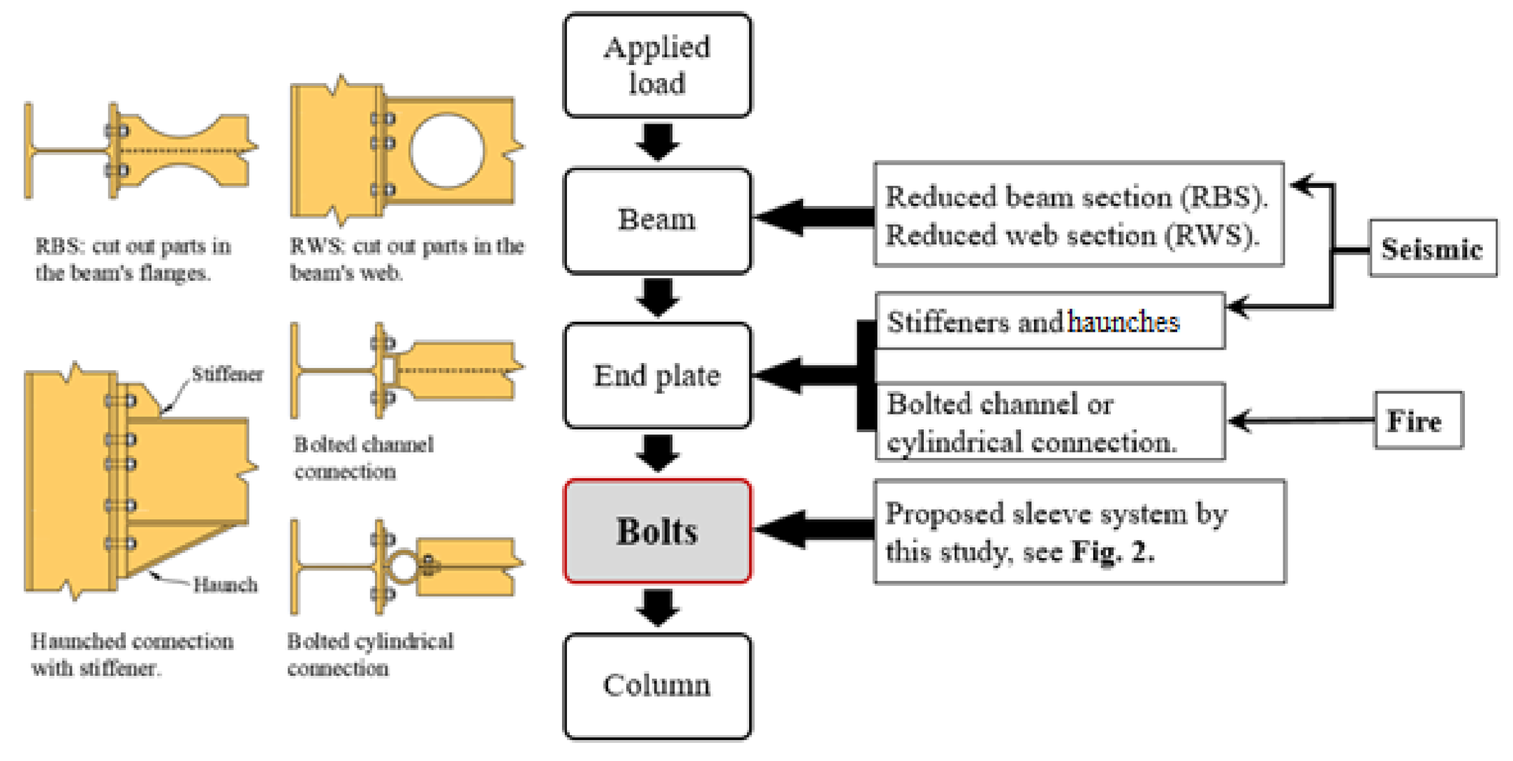
The performance of steel structures subjected to extreme loading has received increased attention in recent years [1,2,3,4]. Existing studies have highlighted the significance of connection configuration and associated parameters in enhancing the overall structural performance and avoidance of progressive collapse. Due to the limited ductility provided by the connection components, researchers have often focused on various methods to enhance the ductility of connections by increasing their rotational capacity; see Figure 1. Note that in Figure 1, connections for fire and seismic actions are included to illustrate the various concepts to enhance the ductility under different extreme load scenarios. It should also be noted that these extreme scenarios may occur together [5,6]. The concept of a structural ‘fuse’, i.e., a zone undergoing severe plastic deformation being formed in the floor beam, is often used for seismic design of steel frames. Development of the fuse requires a strong connection relative to the beam section. This can be achieved by either strengthening the connection region (using stiffeners and haunches) to avoid plasticity of any component of the connection [7], or weakening the beam by trimming away steel parts from the beam flanges (RBS) [8] or from the beam web (RWS) [9] at designated locations. During a fire event, a higher rotational capacity of connections is generally required in order to allow the beam to develop into the catenary phase without failure of the connection components. Thus, researchers have proposed formed end plates that can plastically deform during the catenary action [10,11]. It is clear from the previous discussion that improving the ductility relies on modifying either the stiffness of the beam or the end plate. The rotational capacity of the steel connection is largely controlled by the least ductile members within the load path. These are usually the bolts [12,13]. Traditional analysis and design of T-stub connections treats the bolts as a boundary condition to the end plate [14]. Consequently, high elongation of the bolt is required to achieve high rotational capacity of the connection [15]. In common practice, the most frequently used bolts tend to be from high-strength steel grades of 8.8 and 10.9 which reach their ultimate strength at a strain of ~0.05 [16], followed by a sudden fracture, while mild steel can achieve a strain of 0.2 [17] without failure. In addition to this, the relatively small length of the bolt leads to a reduced contribution to the connection’s rotational capacity in comparison to the end plate.
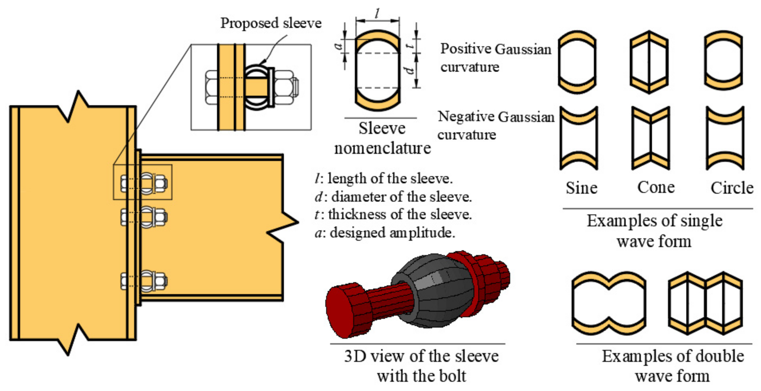
This present study proposes a novel technique to increase the rotational capacity of end plate connections by enhancing the bolt contribution to the system behaviour. Figure 2 schematically illustrates the proposed system. A steel sleeve with designated length, thickness and wall curvature is placed over the bolt between the end plate and the washer. The sleeve is a shell of revolution that resists the applied load by a combination of membrane and bending stress. The bending stresses become significantly large as the ratio of sleeve thickness to radius of curvature is increased. The curvature in the sleeve wall ensures that the sleeve ultimately fails in bending rather than by instantaneous buckling. This curvature can be defined based on the amplitude at the mid-length of the sleeve and the corresponding geometrical equation of the wave form. Theoretically, there are countless numbers of geometrical configurations, including the wave form and the number of waves, however the practical constraints posed by the manufacturability, the cost and optimum structural performance can limit these alternatives. Examples of these various wave forms are shown in Figure 2. Positive and negative Gaussian curvature are applicable for the same wave form. However, the latter requires washers with very specific dimensions as the outer radius of the sleeve can be larger than the washer radius after introducing the amplitude. Furthermore, the bearing between the sleeve with negative Gaussian curvature and the washer can result in high internal forces in the washer which may require a non-standard thick washer. Therefore, only the sleeve with the positive Gaussian curvature is considered in this study.
The basic concept of the proposed method has been previously validated by the authors [18]. The previous analysis concluded that the proposed sleeve significantly improves the rotational capacity of connections, required for the survival of the beam to avoid progressive collapse, without changing the initial stiffness of the standard configuration of the connection. However, the main aim of the previous investigation [18] was to prove the concept of the sleeve device while considering limited connection parameters and limited failure modes. In the present study, extensive analysis of the sleeve device, including different failure modes and various connection parameters, is considered. This paper will limit its focus to the single sinusoidal waveform (SSW) sleeve configuration. A sine wave is considered as it is frequently used to define the initial imperfection profile of shells for buckling analysis [19].
2. FE Model
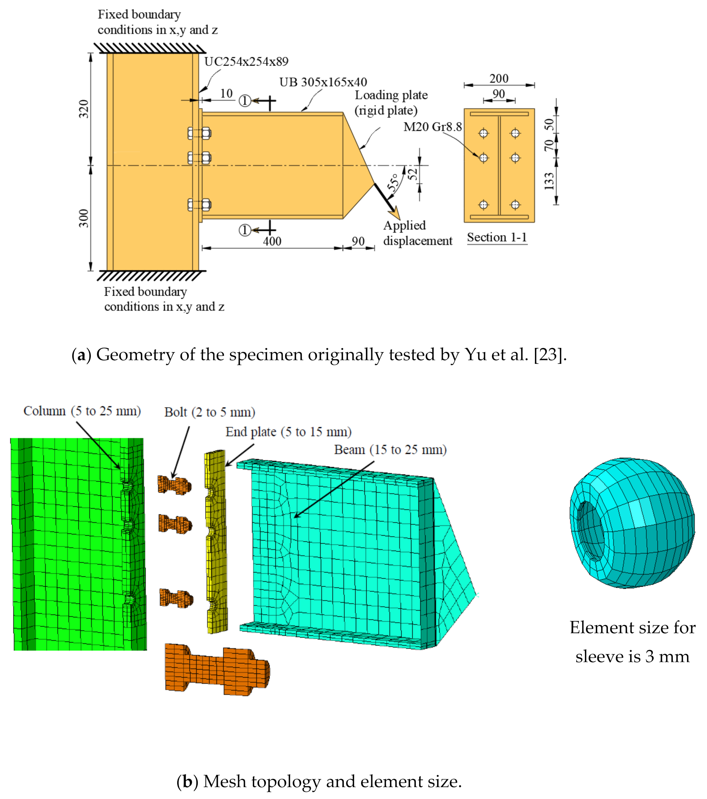
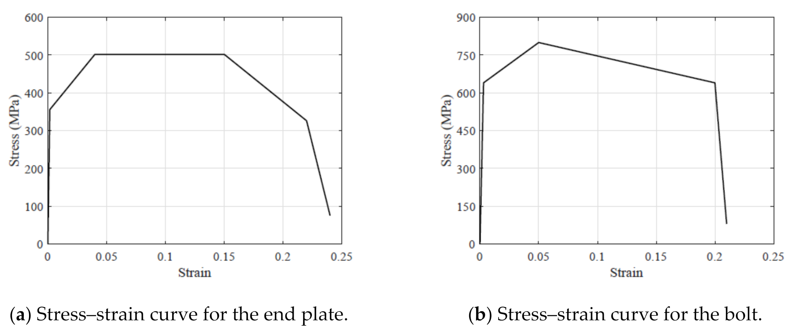
A detailed description of the FE model has been given in a previous paper by the authors [18], however the key details, along with model validation studies, will be described herein. A numerical model of the connection shown in Figure 3a is developed using ABAQUS/Standard version 6.2 [20]. All elements have been defined as solid, 8-node elements (C3D8R) while the rigid body designation is used to simulate the loading plate. The total number of elements in the mesh was 4375. The interaction between contact surfaces (bolt head, column flange and the end plate) was adapted using an interaction equation with a friction coefficient of 0.2 to simulate the tangential behaviour with a relative sliding between the contact surfaces during the analysis. It should be noted that the FE results were found to be not sensitive to the friction between surfaces, consistent with that observed in [21]. The normal behaviour is modelled using a hard contact interaction, which constrains the nodes on one surface to avoid penetrating the other surface. For the parts with stress concentration, such as the bolts and head plate, a fine mesh is defined. To obtain the optimum size of the mesh, a mesh convergence analysis was carried out and the final results are presented in Figure 3b. The damage and fracture of the material were captured using the ductile damage model which is available in the ABAQUS FE version 6.2 tools. The yield stress of steel material is 356 MPa whereas the ultimate stress is 502 MPa based on the recommendation of Eurocode 3 (Part 1–2) [22] and according to the corresponding tensile test coupon specimens [23]. High strength M20 bolts of grade 8.8 were examined. The stress–strain curve for the plate material and the high strength bolt are shown in Figure 4. The damage parameters of material are defined following Pavlovic et al. [24] and Shaheen et al. [16], with the lowest damage evolution variable value considered during the analysis being 0.9 to avoid a sudden drop in stress at the material point, which can cause dynamic instability and convergence problems. Table 1 and Table 2 illustrate the damage variable (D) and the plastic displacement (upl) for bolt and plate, respectively. A detailed description of the material modelling approach can be found at Shaheen et al. [16].
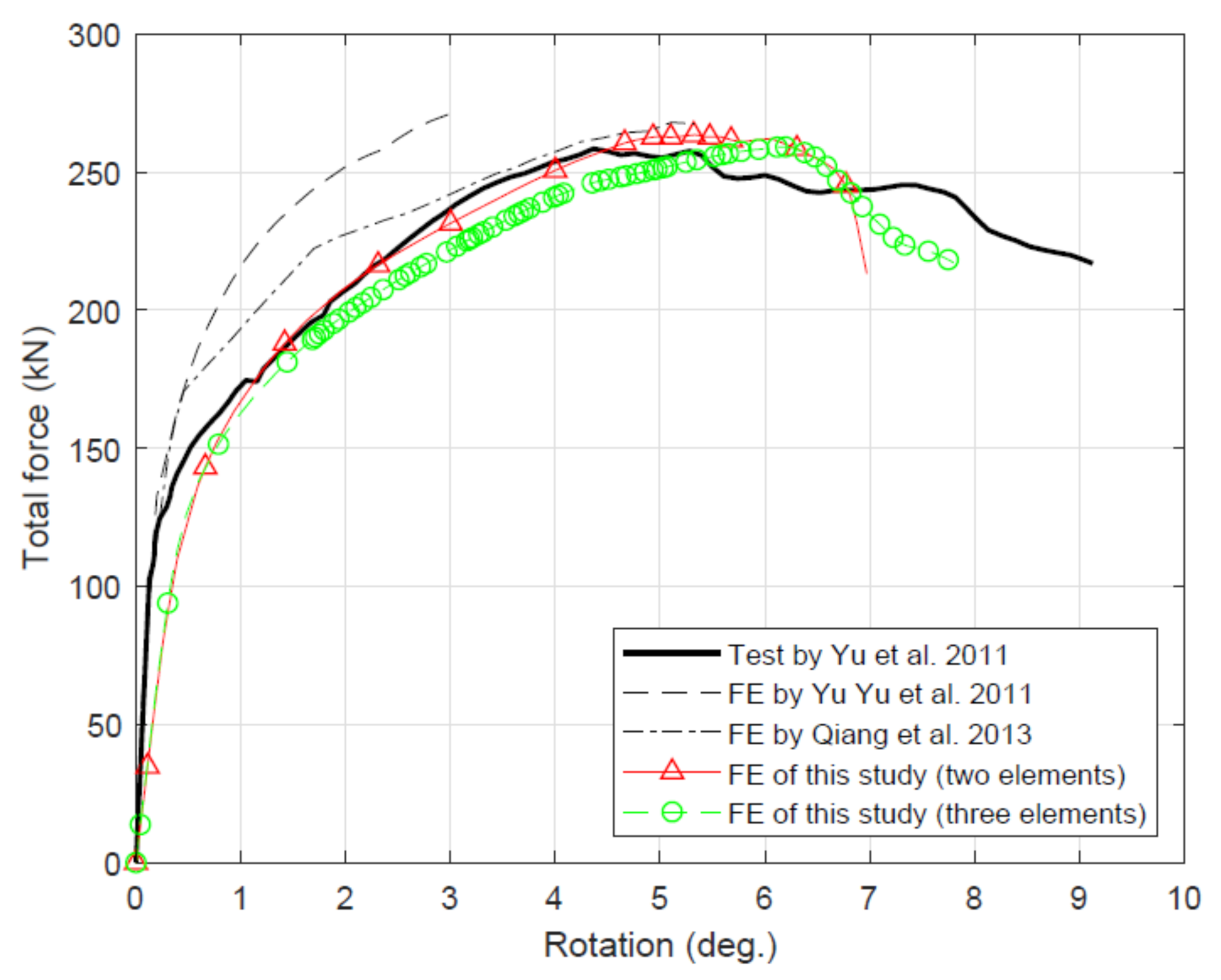
The FE model is validated against the connection specimens tested by Yu et al. [23] at ambient temperature. The geometry of connection is shown in Figure 3a. The applied displacement is inclined by an angle α with respect to the beam’s axis to produce different combinations of shear and tying force. One half of the connection is considered as the connection geometry and the applied load are symmetric. The Newton technique with default matrix storage is employed here to carry out an incremental analysis. The analysis was completed after 10 min using an Intel i7-8700 processor with a clock speed of 3.2 GHz. Figure 5 depicts a comparison of the force–rotation relation obtained from the FE model and the experimental test. A mesh sensitivity study using two and three elements across the end plate and the column flange was carried out. It was found that both mesh densities recorded similar responses, thus two elements were selected to reduce the computational time. The result of the FE simulation of the present study is in good agreement with the result of the experimental work within the elastic and inelastic ranges. There is a slight difference between the FE and the test results in the post-peak region, however the capacity of the connection is captured accurately which is of interest to this study. It should be noted the FE models undertaken by Yu et al. [23] and Qiang et al. [25] did not consider the material damage.
3. Numerical Investigation
The same connection described in the previous section was re-analysed using the proposed sleeve system. The analysis was carried out based on a sleeve thickness of 5 mm with a steel grade of S355. Moreover, the load was applied perpendicular to the beam axis. In real application, the sleeve should be inserted between the end plate and the washer for every bolt in the connection. To decrease the computation time of the analysis the adjacent bolt to the compression flange was ignored depending on the nature of the applied loads. A comprehensive numerical investigation was conducted using ABAQUS software and the influence of the following parameters were examined:
- Thickness of the end plate (thick/thin).
- Bolt spacing.
- Thickness of the sleeve wall.
- Length of the sleeve.
3.1. Performance of Connections with Thick End Plate
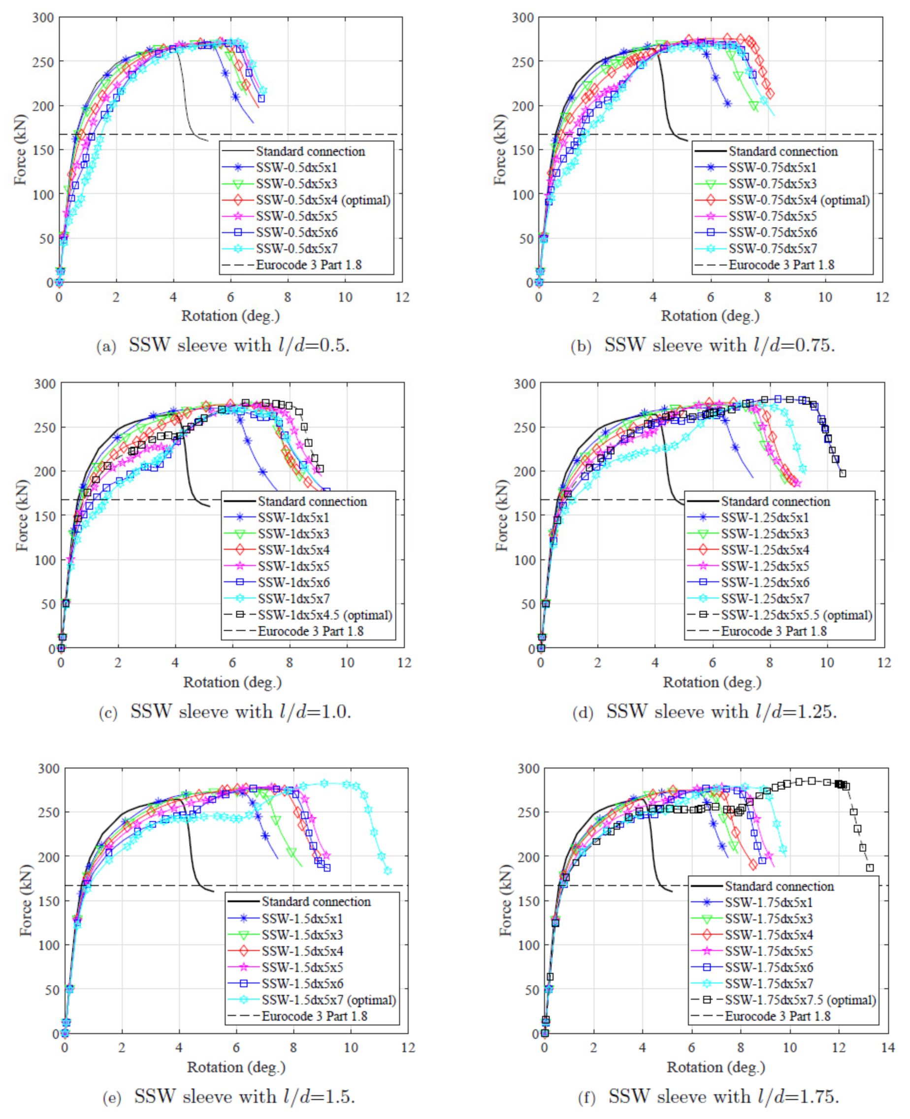
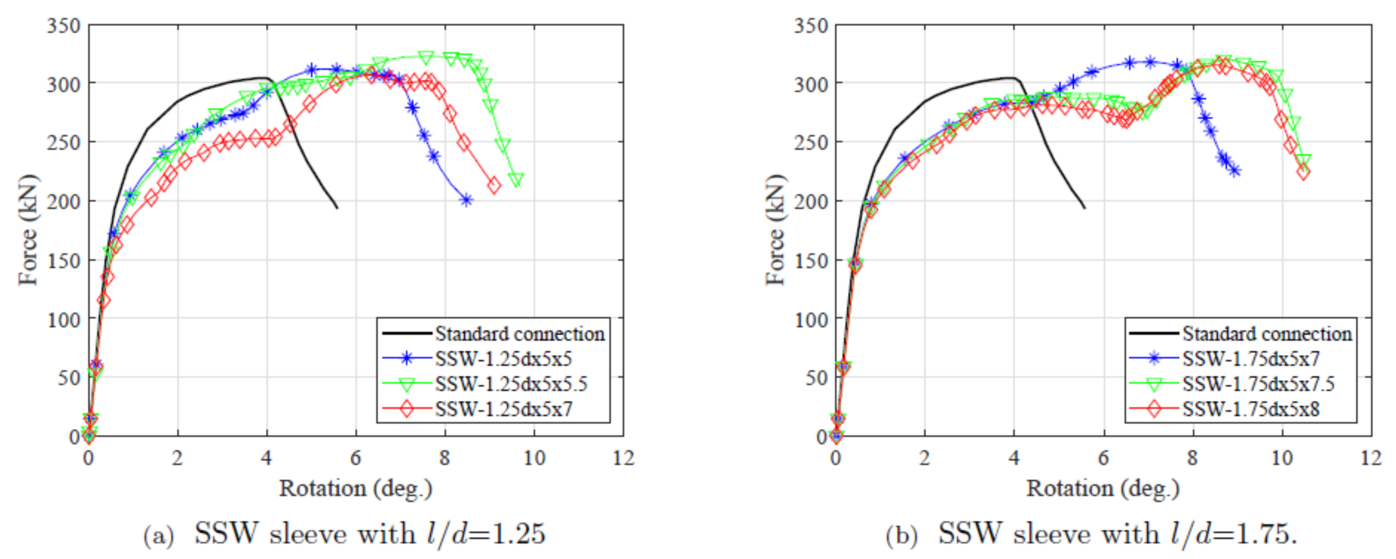
The behaviour of connections with SSW sleeves compared with the standard configuration (i.e., no sleeves) are illustrated in Figure 6; the capacity of the connection based on Eurocode 3 (part 1–8) without partial safety factors is plotted for comparison purposes. The elastic response of the connections with the sleeves is consistent with the standard connection up to the Eurocode strength, particularly for high ratios (refer to Figure 6 for and definitions). The flexural rigidity of the sleeves with the same amplitude is proportionate with the ratio. In case of sleeves with ratio of 0.5, a flexible response of the connection is obtained for the amplitude that provided the highest rotational capacity, 7 mm. Therefore, the optimal amplitude was restricted to 4 mm instead. Overall, it is preferable to use ratios higher than 0.75 to capture the same initial rotational stiffness of the standard connection, otherwise the change in connection rigidity should be checked.
Table 3 summarises the strength and rotational capacity of the sleeved connections. It is clear that connections with the sleeve recorded a significantly higher ductile response compared with the standard configuration, depending upon the amplitude value for the same wavelength. The increase in the rotational capacity ranged between 37% for the sleeve with an ratio of 0.5 and 146% for the sleeve with an ratio of 1.75. Additionally, the sleeved connections achieved a slightly higher load-bearing capacity than the standard configuration owing to their ductile response.
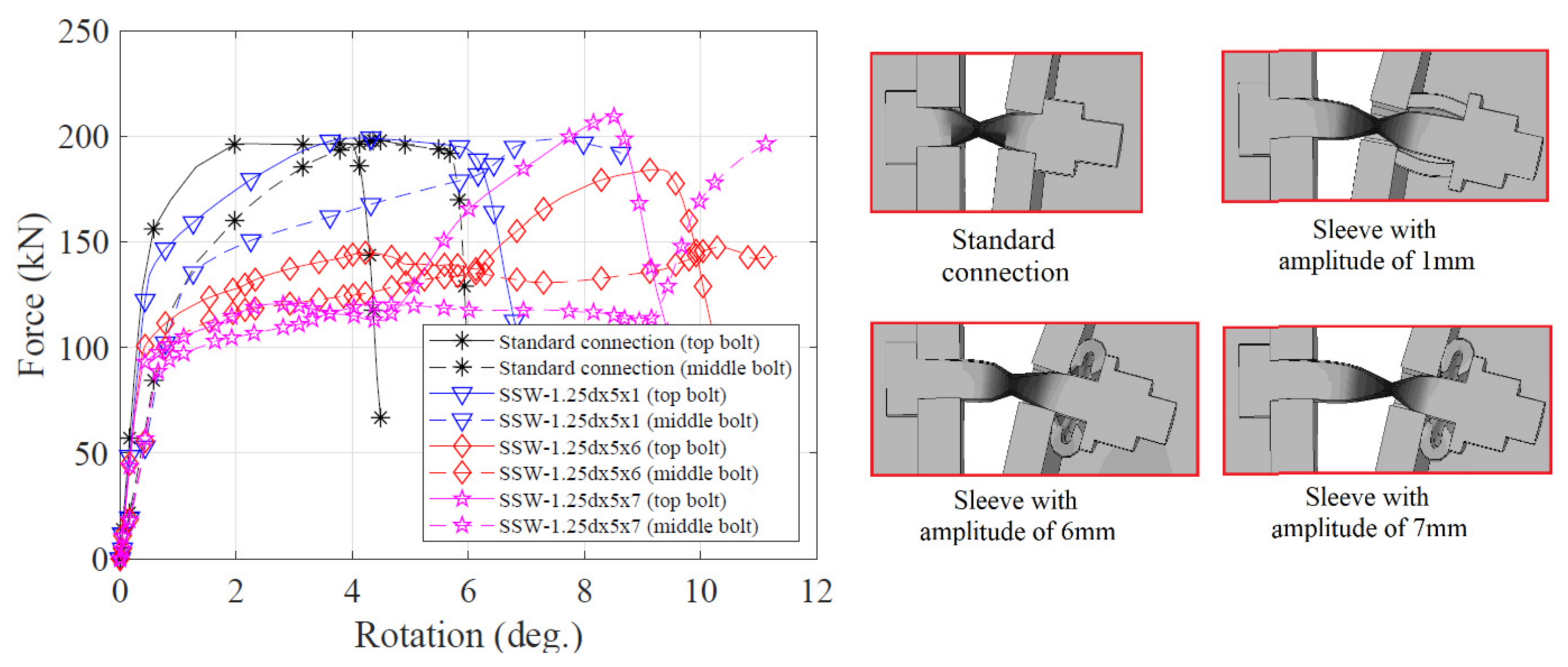
To fully understand the connection performance, the tension forces developed in the bolts are determined for three different amplitude values with the same ratio of 1.25 and the tension force developed in the standard connection is plotted for comparison as shown in Figure 7. The bolt force in the standard connection increases rapidly followed by restricted plastic displacement. The sleeved bolts with large amplitudes showed similar initial response, exhibited significant high plastic deformation and then escalated to the peak value when the sleeve jammed between the washer and the end plate. The deformed shapes at the end of the analysis for the top bolt are shown on the right-hand side of the figure. When a small amplitude value of 1.0 mm was used, the sleeve was rigid inasmuch as the bolts failed without observing any bending deformation in the sleeve. For amplitudes of 6.0 mm and 7.0 mm, the sleeves exhibited severe deformation and eventually crushed between the end plate and the washer before bolt failure, however the latter crushed prematurely due to its lower bending capacity. The optimal amplitude is a threshold value between the amplitude that provides a rigid sleeve and that provides a highly flexible sleeve which prematurely interlocks with the end plate and the washer.
3.2. Behaviour of Connections with a Thin End Plate
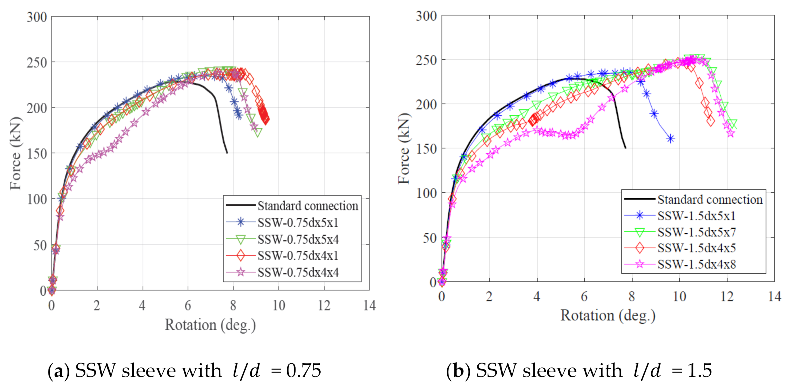
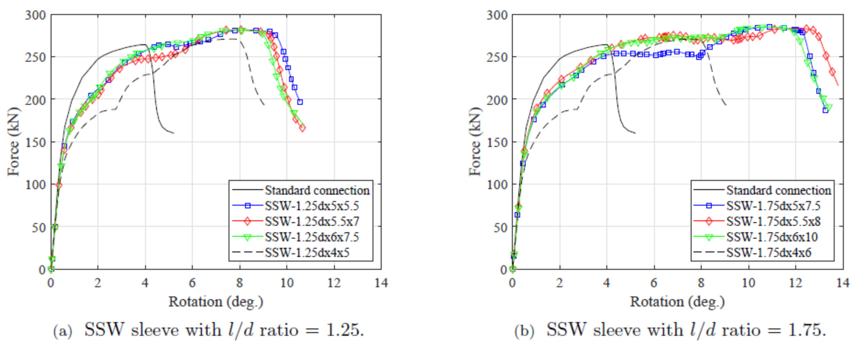
The force-rotation behaviour of the connection with plate thickness of 10 mm is inspected; here the failure is controlled by the end plate. Figure 8 depicts only two amplitudes for each sleeve with 5.0 and 4.0 mm thickness to represent rigid and flexible sleeve behaviour. For sleeves with 5.0 mm thickness, it is clear that the rotational capacity of the connection increased by roughly 20 to 60% when 1.0 and 7.0 mm amplitudes were used with the ratio of 1.5. It should be noted that the same sleeve parameters with the thick end plate (see Section 3.1) were responsible for increasing the rotational capacity of the connection by 60 and 146%, respectively. This is attributed to the premature failure of the end plate before the sleeve developed severe bending deformations. The sleeve capacity can be reduced by either increasing the amplitude or reducing the thickness to create the weakest element in the load path in order to provide a higher ductility response. The sleeve with thickness of 5.0 mm required a high amplitude value so that the sleeve capacity was less than the force at plate failure, thus a sleeve thickness of 4.0 mm was used instead. It is clear in Figure 8 that the initial stiffness and the capacity of the connection are not affected by the sleeve with the smaller thickness of 4 mm, however the behaviour within the plastic range of the connection was more flexible in comparison with the standard configuration. Furthermore, the thin end plate caused uneven load distribution on the sleeve resulting in limited plastic deformation before the sleeve failure. Thus, it can be concluded that the sleeve device can increase the ductility of the connection with both bolt and plate failure modes. However, adopting the sleeve with thick end plate connections provides a more ductile response than that of thin plates.
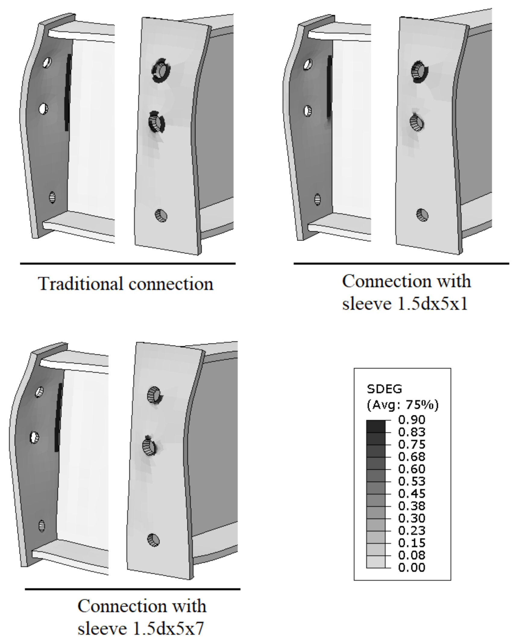
Another positive effect of using sleeves with a thin end plate connection is to reduce the potential of bolt punching failure, which results in a relatively brittle response compared with the plate tearing failure. Figure 9 compares the damage in the end plate for the standard and proposed configuration. The scalar stiffness degradation variable (SDEG) in ABAQUS was used to visualise the damaged parts. SDEG measures the residual stiffness of an element and takes a value from zero (undamaged material) to one (fully damaged material). The punching failure of the bolt was clearly reduced when the sleeve was used and almost eliminated in the case of the flexible sleeve with an amplitude of 7.0 mm. This was attributed to two factors: (1) the ductility provided by the sleeve at the bolt location resulted in load redistribution to a higher rigid zone (such as the weld location) and (2) the plate punching area increased when the sleeve was used, which provided a higher punching capacity.
3.3. Effect of Bolt Spacing
The effect of the bolt spacing on the optimal amplitude value of the sleeve was investigated by analysing the connections with different bolt spacings. The edge distance of the top bolt was changed from 50 mm (2.5 d) to 30 mm (1.5 d) and the spacing between the top and middle bolt was changed from 70 mm (3.5 d) to 60 mm (3 d). The selected distances represent the preferred minimum values used frequently in engineering practice, e.g., [26]. Figure 10 depicts the optimal amplitudes for two sleeves with different ratios. Comparing Figure 10 and Figure 6 for the same ratio, it is clear that the optimal amplitude of the sleeve is irrespective of the bolt spacing as the same optimal amplitude was captured for bolts with different spacing, albeit with relatively lower rotational capacity. In case of the tighter bolt distances, the rotational capacity reduced by about 32% when the ratio was 1.75. This reduction is attributed to the geometric constraint rather than the sleeve parameters. The tighter bolt spacing poses high rotational stiffness to the end plate.
3.4. Effect of Sleeve Thickness
Figure 11 presents a comparison between different sleeve thicknesses; the amplitude of the sleeves shown is selected so that the optimal behaviour is achieved. It is clear that the sleeves with different thickness provide comparable connection behaviour; however, with different amplitudes, the larger the thickness, the higher the amplitude required to reduce the sleeve bending capacity. On the other hand, a sleeve with a small thickness of 4.0 mm is plotted on the figure to illustrate its effect on the connection behaviour. The elastic stiffness and the rotation capacity of the connection was reduced. However, the strength of the connection was not affected as the failure eventually took place in the bolts after the sleeve jammed between the end plate and the washer. It should be noted that the capacity of the perfect (i.e., amplitude value of zero) sleeve with 4.0 mm thickness was less than the bolt capacity. Thus, it is recommended to use the minimum thickness so that the capacity of the perfect sleeve is higher than the bolt capacity. Furthermore, a larger thickness than that required consumes higher quantities of material without adding any benefit to the connection performance.
3.5. Effect of the Sleeve Length
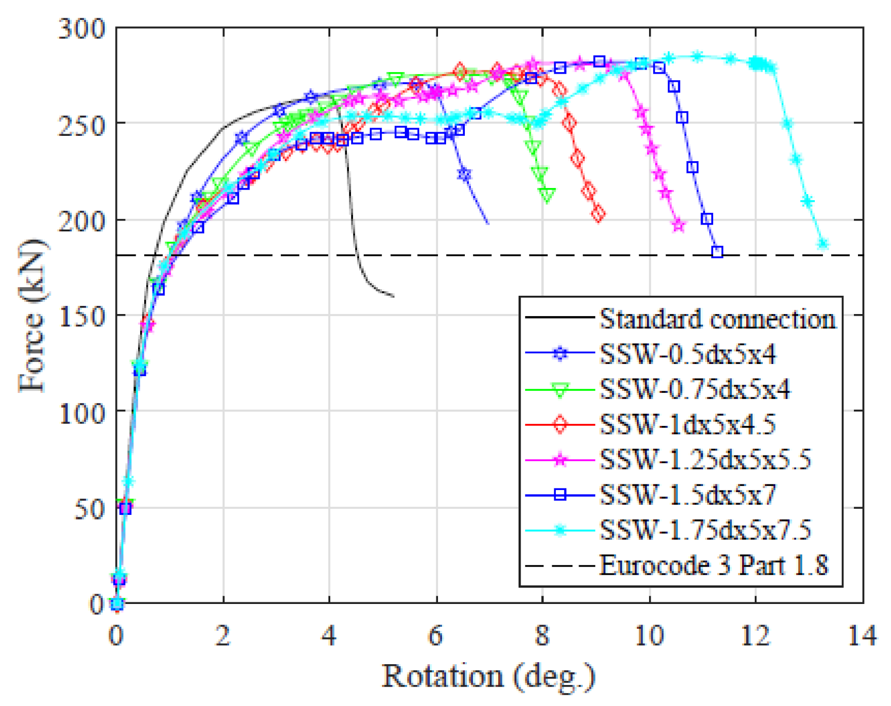
Figure 12 illustrates the force vs. rotation for connections with different ratios at their optimal amplitude using M20 Gr 8.8 bolts. The connection’s rotational capacity is proportional to the ratio. It follows that the optimum sleeve length should be defined based on the required rotational capacity of the connection. Larger ratios can be used where a high ductile response is required. However, the ratio should be limited to the range considered in this study unless rational analysis or experimental tests are undertaken. High values of the ratio result in increasing the radius of curvature with respect to the sleeve thickness; this shifts the force transfer mechanism of the sleeve from combined bending and membrane action to membrane action alone and may result in higher sleeve capacity compared to the bolt itself.
The sleeve length can be defined based on the required increase in the rotational capacity in comparison with the standard configuration, as follows:
where is the required total rotation, is the rotational capacity of the standard connection and is the additional rotation provided by the sleeve as follows:
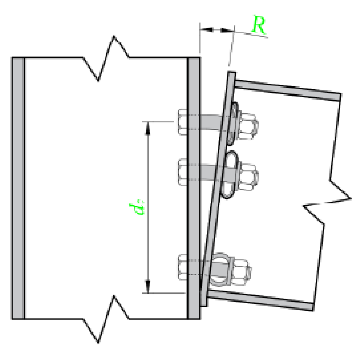
where is the distance between the centre of the compression flange and the top bolt in tension, see Figure 13. is the shortening length of the sleeve under a load equal to the bolt load.
4. Conclusions
This work proposed an innovative device that can improve the rotation capacity of bolted steel beam-to-column end plate connections by inserting a sleeve between the washer and the end plate. A numerical study was carried out using ABAQUS software and the proposed modelling technique was validated against existing related experimental work.
The aim of this work was to investigate the ability of the proposed sleeve to improve the moment rotation capacity of the connection. Using the validated modelling approach, a comprehensive numerical investigation was conducted to examine the effect of the following key parameters on the connection performance:
- Thickness of the end plate (thick/thin).
- Bolt spacing.
- Sleeve thickness.
- Length of the sleeve.
The following conclusions were reached:
- In the case of the tighter bolt distances, the rotational capacity reduced and this reduction was attributed to the geometric constraint rather than the sleeve parameters.
- A simplified equation was presented to evaluate the optimum sleeve length which provided a particular rotation capacity.
- Finally, increasing the sleeve thickness does not add any benefits to the connection performance, hence it is recommended to use the minimum acceptable sleeve thickness as the larger thickness consumes higher quantities of material.
Clearly the use of the sleeve component has potential for the cost-effective enhancement of bolted connection robustness both in new and existing structures. The work presented here must be viewed within the context of the limited geometric and material properties examined. Further exploration of the proposed sleeved-bolt connections, both numerically and experimentally, is required in order to develop comprehensive design guidance. This forms part of the authors’ ongoing research.
Author Contributions
Conceptualization, M.A.S.; methodology, M.A.S. and M.A.G.; software, M.A.S.; validation, M.A.S., M.A.G., L.S.C. and A.S.J.F.; formal analysis, M.A.S., M.A.G., L.S.C. and A.S.J.F.; investigation, M.A.S., M.A.G., L.S.C. and A.S.J.F.; writing—original draft preparation, M.A.S.; writing—review and editing, M.A.S., M.A.G., L.S.C. and A.S.J.F.; visualization, M.A.S., M.A.G., L.S.C. and A.S.J.F.; supervision, L.S.C. and A.S.J.F. All authors have read and agreed to the published version of the manuscript.
Funding
This research received no external funding.
Conflicts of Interest
The authors declare no conflict of interest.
References
- Kiakojouri, F.; de Biagi, V.; Chiaia, B.; Sheidaii, M.R. Progressive collapse of framed building structures: Current knowledge and future prospects. Eng. Struct. 2020, 206, 110061. [Google Scholar] [CrossRef]
- Chen, C.; Qiao, H.; Wang, J.; Chen, Y. Progressive collapse behavior of joints in steel moment frames involving reduced beam section. Eng. Struct. 2020, 225, 111297. [Google Scholar] [CrossRef]
- Galal, M.A.; Bandyopadhyay, M.; Banik, A.K. Vulnerability of Three-Dimensional Semirigid Composite Frame Subjected to Progressive Collapse. J. Perform. Constr. Facil. 2019, 33. [Google Scholar] [CrossRef]
- Wang, Y.C.; Dai, X.H.; Bailey, C.G. An experimental study of relative structural fire behaviour and robustness of different types of steel joint in restrained steel frames. J. Constr. Steel Res. 2011, 67, 1149–1163. [Google Scholar] [CrossRef]
- Suwondo, R.; Gillie, M.; Cunningham, L.; Bailey, C. Effect of earthquake damage on the behaviour of composite steel frames in fire. Adv. Struct. Eng. 2018, 21, 2589–2604. [Google Scholar] [CrossRef] [Green Version]
- Suwondo, R.; Cunningham, L.; Gillie, M.; Bailey, C. Progressive collapse analysis of composite steel frames subject to fire following earthquake. Fire Saf. J. 2019, 103, 49–58. [Google Scholar] [CrossRef] [Green Version]
- Kim, Y.J.; Oh, S.H.; Moon, T.S. Seismic behavior and retrofit of steel moment connections considering slab effects. Eng. Struct. 2004, 26, 1993–2005. [Google Scholar] [CrossRef]
- Lee, C.H.; Jeon, S.W.; Kim, J.H.; Uang, C.M. Effects of Panel Zone Strength and Beam Web Connection Method on Seismic Performance of Reduced Beam Section Steel Moment Connections. J. Struct. Eng. 2005, 131, 1854–1865. [Google Scholar] [CrossRef]
- Shaheen, M.A.; Tsavdaridis, K.D.; Yamada, S. Comprehensive FE Study of the Hysteretic Behaviour of Steel-Concrete Composite and Non-Composite RWS Beam-to-Column Connections. J. Struct. Eng. 2018, 144, 1–13. [Google Scholar] [CrossRef]
- Wang, M.; Wang, P. Strategies to increase the robustness of endplate beam-column connections in fire. J. Constr. Steel Res. 2013, 80, 109–120. [Google Scholar] [CrossRef]
- Liu, Y.; Huang, S.S.; Burgess, I. Investigation of a steel connection to accommodate ductility demand of beams in fire. J. Constr. Steel Res. 2019, 157, 182–197. [Google Scholar] [CrossRef]
- James, A.S.; Roberto, T.L. Bolted steel connections: Tests on T-stub components. J. Struct. Eng. 2000, 126, 91–99. [Google Scholar]
- Silva, L.S.; Santiago, A.; Real, P.V. A component model for the behaviour of steel joints at elevated temperatures. J. Constr. Steel Res. 2001, 57, 1169–1195. [Google Scholar] [CrossRef]
- BSI. BS EN 1993-1-8:2005—Eurocode 3: Design of Steel Structures—Part 1–8: Design of Joints; British Standard Institute (BSI): London, UK, 2005. [Google Scholar] [CrossRef]
- Beg, D.; Zupančič, E.; Vayas, I. On the rotation capacity of moment connections. J. Constr. Steel Res. 2004, 60, 601–620. [Google Scholar] [CrossRef]
- Shaheen, M.A.; Foster, A.S.J.; Cunningham, L.S.; Afshan, S. A numerical investigation into stripping failure of bolt assemblies at elevated temperatures. Structures 2020, 27, 1458–1466. [Google Scholar] [CrossRef]
- CEN. BS EN 1993-1-2:2005—Eurocode 3: Design of Steel Structures—Part 1–2: General Rules—Structural Fire Design, Eurocode 3; European Committee for Standardisation: London, UK, 2005. [Google Scholar]
- Shaheen, M.A.; Andrew, A.S.; Cunningham, L.S. A novel device to improve robustness of end plate beam-column connections. Structures 2020, 28, 2415–2423. [Google Scholar] [CrossRef]
- STimoshenko, P.; Gere, J.M. Theory of Elastic Stability, 2nd ed.; McGraw-Hill: New York, NY, USA, 1963. [Google Scholar]
- ABAQUS. Abaqus 6.19; Dassault Systèmes Simulia Corp.: Johnston, RI, USA, 2019. [Google Scholar]
- Moradi, S.; Alam, M.S. Finite-Element Simulation of Posttensioned Steel Connections with Bolted Angles under Cyclic Loading. J. Struct. Eng. 2016. [Google Scholar] [CrossRef]
- CEN. BS EN 1993-1-2:1995—Eurocode 3: Design of Steel Structures—Part 1–2: General Rules—Structural Fire Design, Eurocode 3; European Committee for Standardisation: London, UK, 1995. [Google Scholar]
- Yu, H.; Burgess, I.W.; Davison, J.B.; Plank, R.J. Experimental and Numerical Investigations of the Behavior of Flush End Plate Connections at Elevated Temperatures. J. Struct. Eng. 2011, 137, 80–87. [Google Scholar] [CrossRef]
- Pavlović, M.; Marković, Z.; Veljković, M.; Signevac, D.B.D. Bolted shear connectors vs. headed studs behaviour in push-out tests. J. Constr. Steel Res. 2013, 88, 134–149. [Google Scholar] [CrossRef]
- Qiang, X.; Bijlaard, F.; Kolstein, H.; Twilt, L. Numerical analysis of high strength steel endplate connections at ambient and elevated temperatures. J. Struct. Fire Eng. 2013, 4, 143–152. [Google Scholar] [CrossRef]
- AISC 360-16, Specification for Structural Steel Buildings ANSI/AISC 360-16. An American National Standard 2016. Available online: https://www.aisc.org/globalassets/aisc/publications/standards/a360-16w-rev-june-2019.pdf (accessed on 8 October 2021).
Figure 1.
Various methods to increase the ductility of connections.

Figure 2.
Proposed connection incorporating the sleeve.

Figure 3.
Geometry and discretisation of FE model (section cut at centre line of the bolt).

Figure 4.
Adopted stress–strain curves [18].
Figure 4.
Adopted stress–strain curves [18].

Figure 5.
FE model validation.

Figure 6.
Effect of amplitude on behaviour of connection for (a) SSW sleeve with , (b) SSW sleeve with , (c) SSW sleeve with , (d) SSW sleeve with , (e) SSW sleeve with , and (f) SSW sleeve with .
Figure 6.
Effect of amplitude on behaviour of connection for (a) SSW sleeve with , (b) SSW sleeve with , (c) SSW sleeve with , (d) SSW sleeve with , (e) SSW sleeve with , and (f) SSW sleeve with .

Figure 7.
Tension force developed in the bolts and corresponding deformation of the sleeve at the end of the analysis.
Figure 7.
Tension force developed in the bolts and corresponding deformation of the sleeve at the end of the analysis.

Figure 8.
Effect of the sleeve on the rotational capacity of the connection with thin plate for (a) sleeve with = 0.75 and (b) SSW sleeve with = 1.5.
Figure 8.
Effect of the sleeve on the rotational capacity of the connection with thin plate for (a) sleeve with = 0.75 and (b) SSW sleeve with = 1.5.

Figure 9.
Effect of the sleeve on thin plate failure.

Figure 10.
Effect of bolt spacing on the optimal amplitudes For (a) SSW sleeve with SSW = 1.25 and (b) SSW sleeve with SSW = 1.75.
Figure 10.
Effect of bolt spacing on the optimal amplitudes For (a) SSW sleeve with SSW = 1.25 and (b) SSW sleeve with SSW = 1.75.

Figure 11.
Effect of thickness of the sleeve on connection behaviour For (a) SSW sleeve with SSW = 1.25 and (b) SSW sleeve with SSW = 1.75.
Figure 11.
Effect of thickness of the sleeve on connection behaviour For (a) SSW sleeve with SSW = 1.25 and (b) SSW sleeve with SSW = 1.75.

Figure 12.
Optimal amplitudes of SSW sleeves used with M20 Gr 8.8 bolts, (based on sleeve thickness of 5 mm and grade S355 steel).
Figure 12.
Optimal amplitudes of SSW sleeves used with M20 Gr 8.8 bolts, (based on sleeve thickness of 5 mm and grade S355 steel).

Figure 13.
Total rotation of connection with the sleeve.


Table 1.
Damage parameters for bolt.
| D | upl |
|---|---|
| 0.000 | 0.00000 |
| 0.010 | 0.01894 |
| 0.020 | 0.04077 |
| 0.030 | 0.06507 |
| 0.040 | 0.09171 |
| 0.050 | 0.12066 |
| 0.060 | 0.15192 |
| 0.070 | 0.18558 |
| 0.080 | 0.22172 |
| 0.090 | 0.26050 |
| 0.100 | 0.30210 |
| 0.110 | 0.34674 |
| 0.120 | 0.39474 |
| 0.130 | 0.44646 |
| 0.140 | 0.50238 |
| 0.150 | 0.56313 |
| 0.160 | 0.62951 |
| 0.170 | 0.70267 |
| 0.180 | 0.78416 |
| 0.190 | 0.87632 |
| 0.200 | 0.98280 |
| 0.900 | 1.16609 |
Table 2.
Damage parameters for plate.
| D | upl |
|---|---|
| 0.000 | 0.00000 |
| 0.037 | 0.00516 |
| 0.074 | 0.01126 |
| 0.111 | 0.01821 |
| 0.148 | 0.02601 |
| 0.186 | 0.03469 |
| 0.223 | 0.04432 |
| 0.260 | 0.05497 |
| 0.297 | 0.06677 |
| 0.334 | 0.07986 |
| 0.371 | 0.09447 |
| 0.901 | 0.15576 |
Table 3.
Strength and ductility of connections with SSW sleeve.
| Specimen (SSW) | P/Ptrad | R/Rtrad | Specimen (SSW) | P/Ptrad | R/Rtrad |
|---|---|---|---|---|---|
| 0.5d×5×1 | 1.02 | 1.37 | 1.25d×5×1 | 1.03 | 1.61 |
| 0.5d×5×3 | 1.02 | 1.39 | 1.25d×5×3 | 1.04 | 1.82 |
| 0.5d×5×4 | 1.02 | 1.49 | 1.25d×5×4 | 1.05 | 1.90 |
| 0.5d×5×5 | 1.03 | 1.53 | 1.25d×5×5 | 1.04 | 1.83 |
| 0.5d×5×6 | 1.03 | 1.60 | 1.25d×5×6 | 1.07 | 2.32 |
| 0.5d×5×7 | 1.02 | 1.56 | 1.25d×5×7 | 1.05 | 2.04 |
| 0.75d×5×1 | 1.02 | 1.46 | 1.5d×5×1 | 1.03 | 1.60 |
| 0.75d×5×3 | 1.03 | 1.63 | 1.5d×5×3 | 1.04 | 1.72 |
| 0.75d×5×4 | 1.04 | 1.82 | 1.5d×5×4 | 1.05 | 1.91 |
| 0.75d×5×5 | 1.03 | 1.69 | 1.5d×5×5 | 1.05 | 2.03 |
| 0.75d×5×6 | 1.02 | 1.74 | 1.5d×5×6 | 1.05 | 1.95 |
| 0.75d×5×7 | 1.01 | 1.73 | 1.5d×5×7 | 1.07 | 2.46 |
| 1d×5×1 | 1.03 | 1.55 | 1.75d×5×1 | 1.03 | 1.61 |
| 1d×5×3 | 1.04 | 1.79 | 1.75d×5×3 | 1.04 | 1.73 |
| 1d×5×4 | 1.04 | 1.80 | 1.75d×5×4 | 1.04 | 1.81 |
| 1d×5×5 | 1.04 | 1.94 | 1.75d×5×5 | 1.05 | 2.03 |
| 1d×5×6 | 1.02 | 1.86 | 1.75d×5×6 | 1.05 | 1.95 |
| 1d×5×7 | 1.02 | 1.92 | 1.75d×5×7 | 1.06 | 2.19 |
Publisher’s Note: MDPI stays neutral with regard to jurisdictional claims in published maps and institutional affiliations. |
© 2021 by the authors. Licensee MDPI, Basel, Switzerland. This article is an open access article distributed under the terms and conditions of the Creative Commons Attribution (CC BY) license (https://creativecommons.org/licenses/by/4.0/).
Share and Cite
MDPI and ACS Style
Shaheen, M.A.; Galal, M.A.; Cunningham, L.S.; Foster, A.S.J. New Technique to Improve the Ductility of Steel Beam to Column Bolted Connections: A Numerical Investigation. CivilEng 2021, 2, 929-942. https://doi.org/10.3390/civileng2040050
AMA Style
Shaheen MA, Galal MA, Cunningham LS, Foster ASJ. New Technique to Improve the Ductility of Steel Beam to Column Bolted Connections: A Numerical Investigation. CivilEng. 2021; 2(4):929-942. https://doi.org/10.3390/civileng2040050
Chicago/Turabian StyleShaheen, Mohamed A., Mohamed Ahmed Galal, Lee S. Cunningham, and Andrew S. J. Foster. 2021. "New Technique to Improve the Ductility of Steel Beam to Column Bolted Connections: A Numerical Investigation" CivilEng 2, no. 4: 929-942. https://doi.org/10.3390/civileng2040050