Review

Review of Ceramic Composites in Aeronautics and Aerospace: A Multifunctional Approach for TPS, TBC and DBD Applications

by
Kateryna O. Shvydyuk
1,
João Nunes-Pereira
1,2,
Frederico F. Rodrigues
1 and
Abílio P. Silva
1,*
1
Centre for Mechanical and Aerospace Science and Technologies (C-MAST), Universidade da Beira Interior, Rua Marquês d’Ávila e Bolama, 6201-001 Covilhã, Portugal
2
Centro de Física das Universidades do Minho e do Porto (CF-UM-UP), Campus Gualtar, 4710-057 Braga, Portugal
*
Author to whom correspondence should be addressed.
Ceramics 2023, 6(1), 195-230; https://doi.org/10.3390/ceramics6010012
Submission received: 18 October 2022 / Revised: 21 December 2022 / Accepted: 4 January 2023 / Published: 10 January 2023
(This article belongs to the Special Issue Advances in Ceramics)

Abstract

:
The quest for increased performance in the aeronautical and aerospace industries has provided the driving force and motivation for the research, investigation, and development of advanced ceramics. Special emphasis is therefore attributed to the ability of fine ceramics to fulfill an attractive, extreme, and distinguishing combination of application requirements. This is impelled by ensuring a suitable arrangement of thermomechanical, thermoelectric, and electromechanical properties. As a result, the reliability, durability, and useful lifetime extension of a critical structure or system are expected. In this context, engineered ceramic appliances consist of three main purposes in aeronautical and aerospace fields: thermal protection systems (TPS), thermal protection barriers (TBC), and dielectric barrier discharge (DBD) plasma actuators. Consequently, this research provides an extensive discussion and review of the referred applications, i.e., TPS, TBC, and DBD, and discusses the concept of multifunctional advanced ceramics for future engineering needs and perspectives.

1. Introduction

Advanced ceramics are inorganic, nonmetallic solids, basically crystalline materials of rigorously controlled composition and raw materials that are prepared from powdered materials and fabricated into products through the application of heat, which display properties such as hardness, strength, low electrical conductivity, and brittleness [1,2,3]. In this way, the term advanced ceramics refers to high-performance, high-tech, engineered, fine, or technical ceramics, i.e., materials with highly specialized and unique properties capable of outstanding performance under the most extreme conditions and, consequently, able to solve today’s challenges in research, manufacturing, and use.
Concerning high-performance ceramics, a distinction is made between structural and functional ceramics. Briefly, advanced structural ceramics are conventionally best suited in mechanical, structural, tribological, thermal, or chemical load applications, owing to their chemically inert nature, high compression, flexural strength, and toughness, in addition to their high corrosion, wear, and thermal shock resistance. In contrast, advanced functional ceramic applications are based on their functional capabilities ruled by microstructural effects that involve semiconducting, piezoelectric, ferroelectric, pyroelectric, and superconducting properties. Nevertheless, from a chemical composition perspective, two classes of fine ceramics may be identified: oxide and non-oxide ceramics. Oxide ceramics are recognized for properties such as oxide resistance, chemical inertness, thermal non-conductivity, and electrical insulation with a slightly complex manufacturing process. Conversely, non-oxide ceramics are characterized by low oxide resistance, being extremely hard, chemically inert, highly thermally and electrically conductive (due to their covalent bonding), highly energy-dependent to manufacture, and quite expensive [1,2,3].
Considering the versatility of advanced ceramics, this sector comprises different fields inscribed with new challenges in exploring the concept of multifunctional ceramics, which are materials still with unexplored potential, namely [3]:
-
Structural ceramics where enhancement of the mechanical properties (based on affordable raw materials, optimized technologies, and simulations of the complete process chain) as well as exploration of the reliability of the materials (by auxiliary sensor integration for structural health control or even self-healing ceramics) are mandatory.
-
Miniaturization and integration density of devices and systems. To this aim, better understanding and control of corresponding changes in specific properties of materials, new testing, and measurement methods are crucial.
-
Modeling is a sensitive issue of uplift since complete production chains and faithful multi-scale modeling (digital twins) must be matured for new materials and devices with higher emphasis in cases of coupled (multifunctional) properties.
-
Functional ceramics in which defective structure (atomic and electronic) dissemination should be achieved to take advantage of full temperature dependence.
-
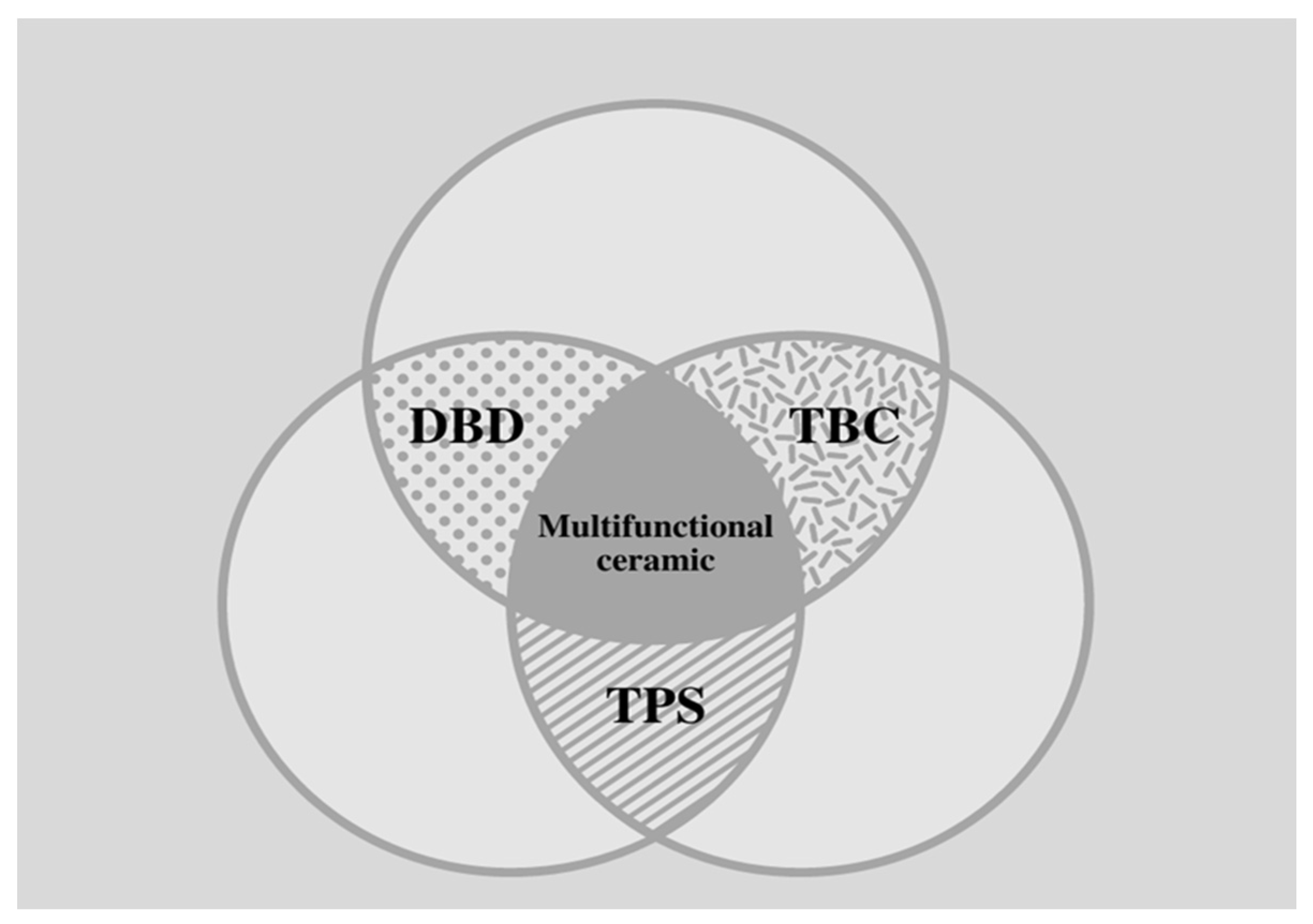
Functional ceramics and property enhancement allow investigation of multifunctional ceramics exhibiting additive effects, based on the coupling of their properties. These effects are little explored, yet they promise to provide and stimulate scientific and technological advancements henceforward.
To leverage the entire innovative potential of advanced ceramics, new lines of research are needed to guarantee the sustainable development and growth of the advanced ceramic materials market using accessible raw materials and preferably with optimized energy costs. Thus, it is essential to know the properties required for a component subject to multiple functions.
The quest for increased performance in the aeronautical and aerospace industries has provided the driving force for the development of high-temperature ceramics with attractive combinations of thermomechanical properties, oxidation resistance, as well as low-to-moderate density [4]. One of the most common and well-known uses for high-performance ceramics in aviation, rocketry, and space technologies is as part of thermal protection systems. This application of ceramics protects the intended components against hazardous aerothermal environments. Examples of thermal protection systems can be encountered in coatings of various heat-resisting materials for aircraft engine nacelle, thrust reverser fire protection, helicopter cowlings, gas turbine engines, satellites, rockets, and re-entry vehicles [5]. In addition to thermal protection itself, the coating enables higher operating temperatures, consequently increasing, for example, an engine’s combustion efficiency, which in turn reduces consumption and harmful residual emissions. Additionally, another application is shielding against foreign objects. Examples of shielding purposes based on advanced ceramic materials include the conservation and safety of propulsion components from existing particles in the surroundings or residuals resulting from poor combustion processes, space debris, or micrometeoroid particles in the case of a spacecraft or rocket [6].
Lastly, an important field of application of high-tech ceramics is electroceramics, a specific category in which materials are combined with specific characteristics, such as piezoelectric and dielectric properties and corrosion and thermal resistance, for use in aircraft instrumentation and control systems, such as missile guidance systems, satellite positioning equipment, ignition systems, instrument display, and engine monitoring equipment [7].
The presented review is specifically focused on the needs of the aerospace and aeronautical industries and research performed to date to find solutions for three current functions: thermal protection system (TPS), thermal barrier coating (TBC), and dielectric barrier discharge (BDB). In this context, the subsequent three subsections aim to provide an in-depth introduction, contextualization, delineation, and analysis of the role of state-of-the-art advanced ceramics in these three domains.

2. Advanced Ceramics in Aerospace and Aeronautical Engineering

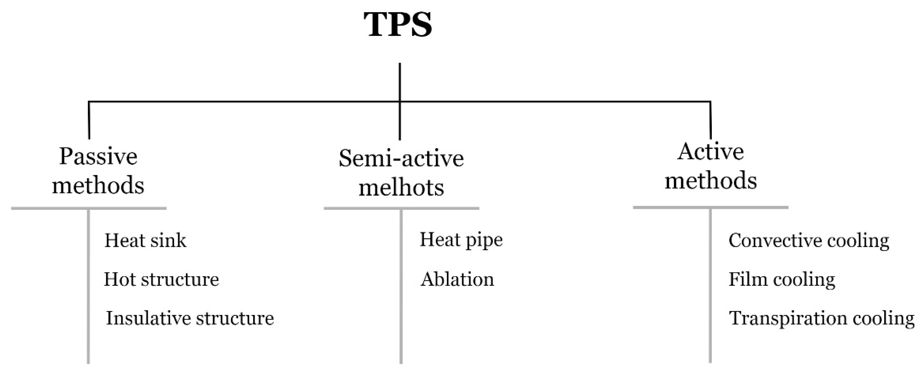
2.1. Thermal Protection System (TPS)

Thermal protection systems (TPSs) play a crucial role in the aerospace and aeronautical industries as they are single point of failure systems that work above all as thermal shields, i.e., a subsystem that protects structures, aerodynamic surfaces, payload of probes, missiles, warheads, and space vehicles from severe aerothermodynamic heating. Accordingly, an effective TPS system must uphold a reliable shield against aerothermal loads, without adding significant weight penalties or compromising the structure of the vehicle. Nonetheless, TPSs also work as structural components and aerodynamic bodies [8,9,10].
The idea of using a protection layer to prevent damage to interior parts of a vehicle dates back to 1920 and is attributed to Robert Goddart, who developed the concept of a heat shield after observing the behavior of meteors entering the Earth’s atmosphere. However, the origin of modern protection systems, as they are known nowadays, can be traced back to the period of World War II. This period, considered the golden age of space flight, ushered countries to invest in developing long-range missiles and rockets capable of leaving the earth’s atmosphere and subsequently reenter to deliver payloads. Several studies were conducted during this period, and it was soon concluded that the vehicles had no capacity for reentering the earth’s atmosphere due to high heat loads and high reentry speeds, as well as a lack of suitable TPS materials. From the mid-twentieth century to date, various TPS technologies have been developed and tested with the aim of ensuring the safety of space vehicles [11].

2.2. TPS Classification

The type of protection on any space-venturing vehicle or, more precisely, on any given area of a vehicle, depends largely on the magnitude and duration of the heat load as well as various operational considerations. In the broadest sense, thermal protection systems can be categorized into three major classes—passive methods, semi-passive methods, and active methods—based on their physicomechanical working principle for thermal management, which can be insulation, ablation, dissipation, or cooling, as shown in Figure 1 [11,12,13]. Uyanna and Najafi (2020) [11] presented a review gathering information regarding TPS methods and materials employed in different space missions throughout the years since the 1950s. Notably, the authors presented a timeframe graph illustrating in-depth the tendencies and preferences of TPSs during the last decades since their conceptualization. More specifically, passive thermal protection systems are the simplest TPS and, as the name itself suggests, have no moving parts. Examples of passive TPS are heat sinks, hot structures, or insulated structures. In turn, semi-passive methods that have been explored and tested for TPS applications, including heat pipes and ablative surfaces. Lastly, convective, film, and transpiration cooling are three different active TPS technologies widely investigated in applications such as rockets and hypersonic vehicle engines. All in all, the correct selection of a TPS includes considering first and foremost the propulsion system of the vehicle, its geometry, and the amount of heat flux on the surface, as well as the time of exposure [8,11,12,14,15,16].
Despite the provided classification, it is important to emphasize that some authors suggest a different grouping of TPSs. Based on the properties and nature of the application of TPS, a distinction is hence made between a TPS that is reusable (also designated insulative or radiative TPS, i.e., non–ablative TPS) and ablative TPS [13,17,18,19,20,21]. It should be noted that this type of classification is a simplification since dissipation and cooling mechanisms are put aside [8]. To cover every aspect, reusable insulative systems are usually relegated to parts of the vehicle that experience less intense heating during reentry. Reusable insulative systems consist of materials that are mechanically or chemically unchanged by flight mission—no mass variation or composition of the materials occurs during their exposure to the hazard environments—and can be relatively safely flown a number of times, with or without service. In contrast, when the vehicle is subjected to very high heat fluxes, ablative TPS can withstand much higher heat loads through the processes of phase change and mass loss [17,22,23]. Ablative forms of TPS include organic polymers and composites, as well as inorganic polymers/oxides and metals.
The insatiable aspirations of the aerospace industry are the source of intense demand for more efficient and powerful vehicle–structure thermal protection systems. To put it simply, severe operating conditions, including higher temperatures, faster speeds, higher stress, and hostile environments require the constant investigation and improvement of available materials in conjunction with cooling systems for TPS applications [23]. Therefore, the TPS of next-generation hypersonic and reentry space vehicles must offer a combination of suitable properties [22], including high melting point (>3000 °C), high softening temperature, low areal density, low recession rate, high impact resistance, high ablation resistance, ability to withstand radiative heating, superior oxidation resistance, thermal shock resistance, high fracture toughness, high-temperature strength, and low-to-moderate thermal conductivity (depending on the area of application).

2.3. Ceramic Materials for TPS Systems

Advanced structural ceramics play a key role in addressing these challenges considering the vast range of improvements they offer, such as weight reduction, longer lifetime, and thus cost savings. Intuitively, oxide ceramics, such as alumina, zirconia, and mullite, appear to be ideal candidates for high-temperature structural applications due to their high-temperature stability, high hardness, and good corrosion and erosion resistance, together with comparatively low costs. Nevertheless, relatively poor mechanical properties, videlicet, creep, fatigue, fracture toughness, large volume change (generated by phase transformation), and significant grain growth above 1000 °C severely limit oxide ceramics as structural components in high–temperature applications [22]. In contrast, non-oxide ceramics, such as nitrides, carbides, and borides, can achieve high strength and excellent creep resistance at elevated temperatures due to their predominant covalent bonding. Unfortunately, the fundamental drawback of these materials is their susceptibility to oxidation [24].
Thus, to overcome the problems associated with conventional ceramics, ceramic matrix composites (CMCs) were developed to achieve damage tolerance and favorable failure behavior. CMCs are called “inverse composites” because, unlike polymeric or metallic matrix composites, the failure strain of the matrix is lower than the failure strain of the fibers. Hence, under load, the matrix fails first. Overall, long-term high-temperature stability, creep resistance, and oxidation stability properties are sought. In essence, CMCs consist of ceramic fibers or whiskers in a ceramic matrix and interphase generally provided by a fiber coating. Both the fibers and matrix can be made of any ceramic material. The choice of systems with similar matrices and fibers is mainly justified by the need to minimize the residual stress associated with a mismatch between the thermal expansion coefficients of the matrix and reinforcement material. Nevertheless, by carefully combining different ceramic matrix materials with especially suitable fibers, new properties can be created and tailored [25,26].
The most commonly used CMCs are non–oxide CMCs, namely carbon/carbon (C/C), carbon/silicon carbide (C/SiC), and silicon carbide/silicon carbide (SiC/SiC). Hybrid composites and composites with nanostructured reinforcements, such as carbon nanotubes (CNTs) and graphene, have paved the way for further investigations. Cho et al. (2009) [27] reviewed the status of the research and development of CNT-loaded ceramic matrix composite materials, whilst Porwal et al. (2014) [28] provided a comprehensive overview of graphene ceramic matrix composite (GCMC) in comparison to polymer composites. Nevertheless, carbon fiber–reinforced silicon carbide (C/SiC) CMCs are among the most famous composites for high–temperature structural applications.
Wei et al. (2018) [29] focused their research on integrated thermal protection systems (ITPS) comprised of a cellular core sandwich panel and filling insulative material in the core. Compared to using metal sandwich panels, ITPS incorporating CMC sandwich panels gave notable advantages of high-temperature resistance up to 1600 °C and areal density of 17.22–30.56 kg/m2, which was much lower than that of reported ITPSs (23.66–88.84 kg/m2). Notably, Heidenreich et al. (2021) [30] studied the shear properties of C/C–SiC sandwich structure samples based on different core types. The results showed that sandwich samples with fold–cores were preferred because they offered higher specific stiffness and effective shear modulus of up to Geff = 6.4 GPa/(g/cm3) compared to sandwich samples based on grid–cores (Geff = 4.2 GPa/(g/cm3)).
Interestingly enough, Huang et al. (2022) [31] investigated a novel SiC coating with a relatively high crack resistance property, in addition to outstanding thermal shock resistance achieved by means of the pack cementation technique. The improvements verified in the microstructure resulted in superior mechanical capabilities, antioxidation performance (900 °C), and thermal shock resistance (up to 1500 °C).
Despite this broad investigation of CMC materials, ultra-high temperature ceramic (UHTC) materials have been the focus of intensive research in recent years in order to extend the temperature range capabilities of state-of-the-art materials in addition to developing components able to withstand larger and multiple aerothermal–chemical loads. Fundamentally, UHTCs encompass carbides, nitrides, and borides of transition metals, e.g., zirconium diboride (ZrB2), hafnium diboride (HfB2), titanium diboride (TiB2), zirconium carbide (ZrC), hafnium carbide (HfC), and tantalum carbide (TaC), that are characterized by melting points above 3000 °C, high temperature strength, and excellent oxidation ablation resistance. This portends that they can maintain non–ablative properties and structural integrity in hazardous environments above 1800 °C for long periods [6,30].
Among UHTC materials, ZrB2 and HfB2 are the most widely investigated. Opila et al. (2004) [32] reported that the addition of SiC up to 30 vol.% improved both the oxidation resistance and mechanical properties of sintered ZrB2–SiC and HfB2–SiC composites. Likewise, Chamberlain et al. (2004) [33] investigated zirconium diboride ZrB2 composites containing 10, 20, and 30 vol.% of either SiC or molybdenum disilicide (MoSi2) prepared by hot pressing. The results exhibited an improvement in the strength of ZrB2, reaching a maximum of ≈1 GPa at 30 vol.% additives. In particular, SiC additives increased the fracture toughness to 5.25 MPa·m1/2. Overall, the addition of MoSi2 and SiC decreased the oxidation rate when compared to monolithic ZrB2. Later, Zhang et al. (2019) [34] proposed a novel eutectic engineered microstructural design of ZrB2–SiC UHTCs to improve oxidation resistance by means of directional solidification.
Notwithstanding the advances in the TPS materials already obtained, continuous investigation led to follow-up research on the strengthening and toughening of UHTCs. By combining the unique properties of UHTCs with the concepts of CMCs, a new class of materials known as fiber-reinforced UHTCMCs (ultra-high temperature ceramic matrix composite) was developed. This class of materials focused on overcoming the inherent brittleness and poor mechanical resistance of bulk UHTCs. Therefore, UHTCMCs are very promising for applications in extreme conditions and are considered the best candidates for a new generation of high-thermal protection materials [35].
The EU-funded project C3HARME aspires to combine the best features of CMCs and UHTCs to design, develop, manufacture, and test UHTCMCs with self-healing capabilities to be achieved in situ by nanosized ceramic dopants. Within this line of reasoning, Sciti et al. (2018) [36] reported that the preferred matrix was essentially based on ZrB2 enriched with secondary phases and different functionalities.
It is worth noting that hybrid technology, i.e., TPSs combined with TBCs, has paved the way for continuous investigations in this domain in the research community.
In 1998, Gary B. Merrill and Thomas B. Jackson released a method of ceramic high-temperature insulation for ceramic matrix composites under high-temperature and high-heat flux environments. The authors explained the thin thickness drawback of TBCs, as well as their thermal and dimensional instability, dictated by conventional application methods, i.e., air plasma spray and physical vapor deposition. Additionally, the inventors highlighted the prolonged high-temperature exposure and cooling constraints of CMCs. Therefore, ceramic compositions comprising a plurality of hollow oxide-based spheres of various dimensions, a phosphate binder, and at least one oxide filler powder were proposed to insulate CMCs and provide them with erosion and thermal shock resistance [37].
As a follow-up in 2007, Gary B. Merrill and Thomas B. Jackson disseminated a method describing the application of an outer thermal barrier coating to a ceramic matrix composite to offer components and/or structures with the high-temperature stability of ceramics without the characteristic brittleness of monolithic ceramics [38].
In parallel, Zhu (2018) extensively reviewed NASA’s evolution of thermal and environmental coatings technologies. Special attention was given to the application of EBC layers to protect the SiC-based ceramic components in gas turbine engines for high-pressure and high-temperature section components and exhaust nozzles. The author described the core problem of nickel-based superalloys reaching their upper temperature limit and how SiC fiber-reinforced SiC/SiC CMCs are perceived as an alternative next-generation turbine engine hot-section material. Typically, silicon-based ceramics and composites, such as SiC/SiC, are selected for this purpose due to their low density, high-temperature creep strength, and oxidation resistance in dry oxidizing environments. However, EBCs are necessary to prevent the SiC/SiC ceramic matrix composite from water vapor attack in the engine combustion process, originated by the volatilization of the protective SiO2 scales on SiC when reacting with water vapor [39].
Additionally, a study by Zhu et al. (2002) investigating the thermal gradient cycle behavior of thermal and environmental barrier coatings on SiC/SiC CMSs was conducted to develop high-performance ceramic coating systems as well as to simulate coating operation temperatures and stress conditions [40].
Carbon fiber-reinforced UHTC composites, consisting of carbon fibers embedded in a UHTC matrix or C–SiC–UHTC matrix, are also a promising class of materials for surpassing monolithic UHTC materials in terms of fracture toughness and thermal shock resistance. Tang et al. (2016) [41] reviewed this topic, including the design, preparation, and properties of such materials for aerospace applications.
Carbon-reinforced ultra-high temperature ceramic matrix (C/UHTC) composite fabrication processes—hot pressing (HT), chemical vapor infiltration (CVI), polymer impregnation and pyrolysis (PIP), and melt infiltration (MI)—were reviewed by Arai et al. (2019) [42]. In detail, the fracture toughness, thermal conductivity, and recession behavior in an oxidizing atmosphere of C/UHTC were evaluated. It was concluded that Zr- and Hf-based mechanical behavior and thermal conductivity can be tailored by varying their fiber volume fraction and by the formation of a “weak” interface using fiber coatings. Further, MI was pointed out as an efficient approach for the preparation of C/UHTC composites.
An extensive aerothermodynamic characterization of UHTCMCs produced by sintering technology, including ZrB2–SiC matrix reinforced with short random or continuous fiber. was performed by Mungiguerra et al. (2022) [43]. This study tested conditions aiming to reproduce the typical heat fluxes (around 2 MW/m2) and stagnation pressure (around 70 kPa) of a reference re-entry mission with a high amount of dissociated oxygen, i.e., approximately 22 wt.%. All of the materials successfully passed the base qualification and cycling exposure three times, achieving temperatures of approximately 2000–2500 K. The materials developed and tested were ZS–SF and ZSY (53 vol.% ZrB2–SiC matrix, 45 vol.% chopped carbon fibers, with porosity below 2%. The difference between the two samples was the SiC content with respect to the UHTC matrix); ZSY–LF (45 vol.% ZrB2–SiC matrix, 50 vol.% continuous carbon fibers (0°/90° configuration) with porosity of 5%); and CS (baseline C–SiC material loaded with 10 vol.% ZrB2 phase and porosity of approximately 10%). Altogether, the capability of these novel UHTCMCs to maintain their functionality and structural integrity after repeated exposure was confirmed, making them extremely appealing for future reusable TPS applications.

3. Thermal Barrier Coating (TBC)

Thermal barrier coating (TBC) systems are generally explored to enhance energy durability and therefore the efficiency of hot components of aero-engines, gas turbines, and parts for combustion power plants. Thus, TBCs protect the substrate structure by preventing them from experiencing high temperatures and harsh environmental degradation. Consequently, thermal barrier coating, as a surface modification technique, provides resistance to wear, oxidation, thermal shock, and corrosion for prolonged service times and thermal cycles without failure, increasing both the efficiency and lifetime of the desired components [44,45,46]. Ultimately, TBCs are multifunctional systems that provide a wide range of benefits, such as [47]:
  • shielding of metallic structure,
  • decreased thermal conductivity,
  • high thermomechanical stability,
  • increased exhaust gas temperature,
  • increased engine power efficiency,
  • decreased fuel consumption, and
  • increased lifespan of parts through decreased fatigue and stress.
The concept of “thermal barrier coating” is believed to have been first introduced by the National Advisory Committee for Aeronautics (NACA) and the National Bureau of Standards (NBS) with the publication of the earliest turbine blade-oriented ceramic coatings research entitled “Review of an Investigation of Ceramic Coatings for Metallic Turbine Parts and Other High–Temperature Applications” by W.N. Harrison, D.G. Moore, and J.C. Richmond in 1947 [48,49,50]. The pioneer ceramic coatings for aerospace applications were frit enamels used in aircraft engines throughout the 1950s [50]. With the development of the flame-sprayed ceramic coating technique, further applications included the protection of sheet metal in jet engines and rocket engine thrust chambers. With regard to the materials appraised for TBC purposes, flame-sprayed zirconia-calcia coatings were widely applied to the regeneratively cooled XLR99 thrust chamber for the X-15 experimental rocket planes. In addition, “modern” plasma-sprayed TBCs began to be employed on hot section transition ducts and other hot section sheet metal components in commercial gas turbines in 1970 [51]. Most recently, the microstructure of thermal barrier coatings, the materials applied, the coating preparation technologies, and the failure mechanisms, as well as lifetime prediction models, have all been part of the different branches of extensive investigation [48].

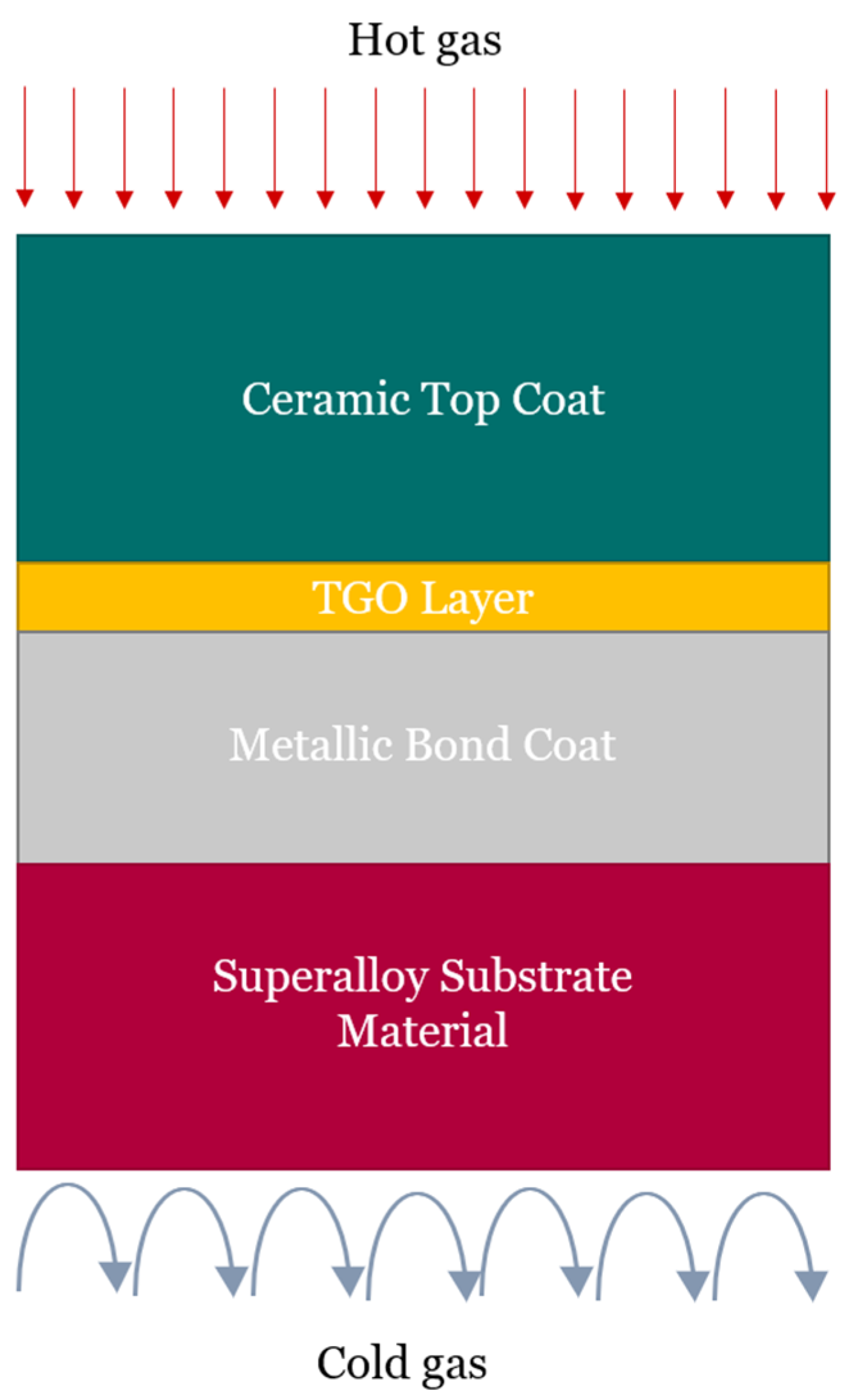
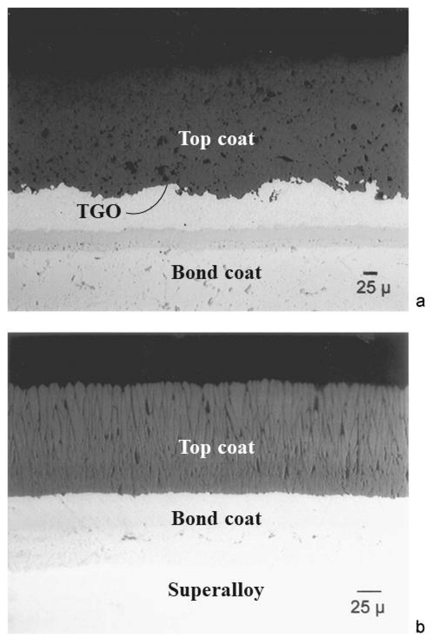
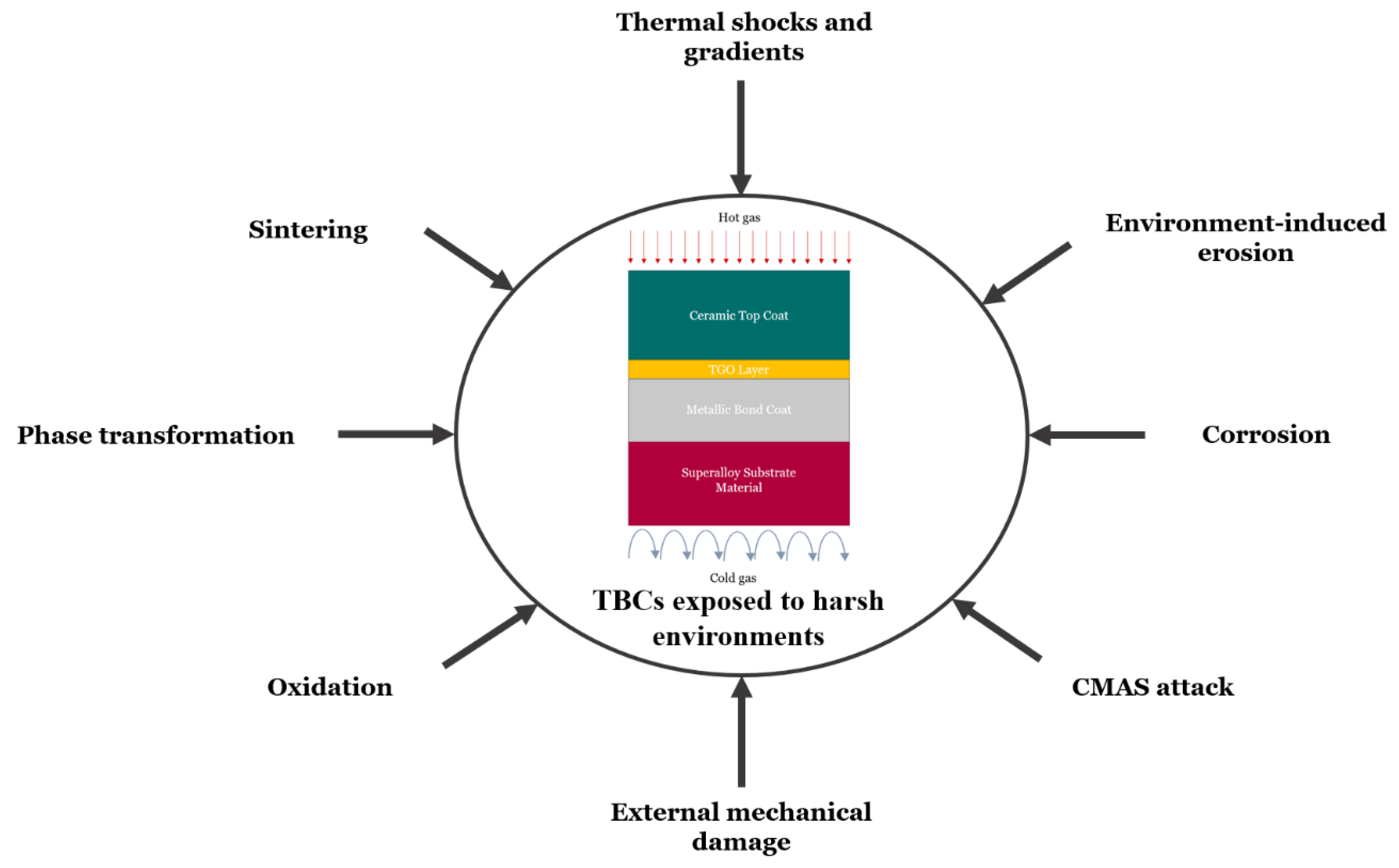
3.1. TBC Structure, Fabrication Techniques, and Failure Mechanisms

A great deal of effort has been devoted over the past few decades so that TBCs systems could enable higher operating temperatures and reduce cooling systems costs, thus improving the overall capabilities and effectiveness of components [47]. Irrespective of the evolution achieved, the stability of TBC systems continues to be a major concern of the scientific community. During operating service, TBCs are exposed to complex phenomena, such as thermomechanical stress, corrosion by foreign objects, erosion, diffusion, oxidation, phase transformation, and sintering [46]. In essence, the TBC is a complex, multilayered, and multi-material coating system composed of (1) a top coat, (2) a metallic bond coat, (3) a thin thermally grown oxide (TGO) layer, and (4) a superalloy substrate (structure), as depicted in Figure 2 [45,47].
The ceramic top coat also referred to in the literature as the “TBC layer”, is generally, as the name itself implies, a ceramic material layer that provides, more importantly, thermal protection to the substrate, but also strain tolerance and thermal shock resistance for components through reduction of heat transfer. Consequently, to decrease the temperature of the metal substrate, this top coat should have essentially low thermal conductivity [44,45,47]. A state-of-the-art TBC top coat material is yttria-stabilized zirconia (YSZ) composed of ZrO2 with 7–8 wt.% Y2O3 because it has excellent thermomechanical properties, such as [44,45,52]:
  • very high mechanical strength,
  • very high wear resistance,
  • very high erosion resistance,
  • high impact resistance,
  • high corrosion resistance,
  • high chemical resistance,
  • very low thermal conductivity, and
  • relatively high coefficient of thermal expansion when compared to other ceramics.
Following this, the TGO layer is created via the diffusion of oxygen from the bond coat through the top coat of metallic elements during manufacturing and operation processes. The TGO layer acts as a protective layer to retard further thermal and oxidation diffusion. Nonetheless, the TGO layer may increase the internal stress in the TBC system, hence potentially originating cracking at the interface between the bond and top coats. This phenomenon may eventually lead to the unwanted spallation or delamination of the top coat in service [46,47,53].
Lastly, the metallic bond coat acts as a precoating interface between the substrate and top coat, aiming to protect the superalloy substrate from oxidation and corrosion, increasing the adhesion between the layers, and ultimately guaranteeing the structural integrity of the coating by matching the thermal properties and stress between the substrate and ceramic coating [46,47]. Two types of metallic bond coats are common. The first-generation bond coat of platinum (Pt)-modified aluminide is recognized for having good stabilization and adhesive strength of the coating by reducing inter-diffusion between the coating and substrate layers. Unfortunately, Pt is an expensive component and it does not possess desirable mechanical robustness at high temperatures [48,54]. Another second-generation bond coat consists of the MCrAlY coatings. These include NiCrAlY, CoCrAlY, and NiCoCrAlY, which have good oxidation and hot corrosion resistance [44,48,55]. Moreover, these compositions can be enhanced by adding Ta (Tantalum), Nb (Niobium), Re (Rhenium), Hf (Hafnium), Zr (Zirconium), and/or other components to improve the high-temperature performance, extend the lifespan, and match specific requirements [44,48].
Concerning the fabrication techniques of TBCs, several different methods are known and ready to be used, e.g., atmospheric plasma spraying (APS) and electron beam physical vapor deposition (EB-PVD), whereas others are promising candidates to achieve better results in the near future, such as plasma spray physical deposition and vapor deposition technology. Plasma-sprayed (PS) TBCs were proposed in the 1960s. Subsequently, several different variations of this technique appeared, including APS, low-pressure plasma spraying (LPPS), solution precursor plasma spraying (SPPS), vacuum plasma spraying (VPS), and protective atmosphere plasma spraying (PAPS).
Among them, APS and LPPS are the two main methods utilized in TBC deposition since they are characterized by low cost, rapid deposition rate, high efficiency, and easy management [48]. APS and LPPS are distinguished by their complex horizontal laminated structure [55]. Substantially, the acceptable porosity of APS TBCs lies in the range of 10–15%, which is essential for high strain compliance and effectively further reduces thermal conductivity. Despite the advantages that these methodologies offer, inter-lamellar pores, microcracks, and microstructural defects give way to the possibility of delamination and spallation. Therefore, APS and SPPS are useful for structures with large volumes and weaker mechanical properties needed, i.e., combustion chambers and stator vanes [47,48,56,57].
In the 1980s, the focus shifted to TBC deposition techniques by EB-PVD, which was quickly popularized with the advent of low-cost EB-PVD equipment in the 1990s. In 1994, Thomas E. Strangman disclosed a methodology to provide a superalloy substrate with a TBC coating that included a ceramic layer resistant to sintering during high-temperature gas exposure. Additionally, the protective ceramic layer was shown to have a columnar microstructure due to the electron beam physical vapor deposition procedure [58]. Overall, EB-PVD coatings exhibit excellent aerodynamic properties, with better surface roughness, and they do not block fine cooling holes. EB-PVD coatings exhibit a columnar morphology within randomly distributed multi-scale porosity, as well as a thin layer in the form of equiaxed grains near the interface between the bond and ceramic top coat. This microstructure improves the TBC system’s strain tolerance and thermal shock resistance, in addition to relaxing the thermal expansion mismatch stress. Nonetheless, EB-PVD TBCs unfortunately have higher thermal conductivity and lower thermal insulation than APS TBCs [47,48,56,57].
Figure 3 illustrates the contrast in the coating produced by the EB-PVD process which, as mentioned, exhibits a columnar morphology whereas the coating deposited via APS exhibits a lamellar morphology.
For the sake of completeness, as explained, a critical property of solid materials is surface morphology. The microstructural properties are an important link between material processing and their performance. Therefore, microstructure quality control is essential for all material processing routes [60].
Apart from their morphology, the functional properties of materials are governed by the composition considered [61]. Therefore, an increasingly growing development in the literature of functional coatings is based on a layered, also known as graded, functional coating architecture, since one individual layer or the complete thin film system may simultaneously fulfill several functions, among them mechanical, thermal, and electrical. Consequently, it is increasingly important to assess and optimize the TBC layer characteristics not only individually, but in their complexity, with respect to their metallic compatibility and designed applications [62].
In view of reducing the weight of structural elements, Kaczmarek et al. (2013) studied the deposition of carbon coatings at room temperature by pulsed laser deposition, which is a promising methodology for mono- and multilayer coatings even at temperatures below 100 K. The authors presented a study on the influence of pressure and composition of the processing atmosphere parameters on the deposition of carbon coatings with a titanium interlayer on an aluminum alloy 7075 substrate [63].
Within the same framework of thought, Deng et al. focused on the design, fabrication, and characterization of deposited graded thermal barrier coatings. More specifically, the authors focused on the assessment of adhesion strength and thermal conductivity of functionally graded YSZ coating by fabricating 2 μm thick lab-scale YSZ coatings. A continuously varying composition profile was produced using the dual-beam pulsed laser deposition method on stainless steel 316 L [64].
TBC failure can occur in a multitude of ways depending on the TBC system and the service conditions due to the sheer complexity of the interactions between the three primary layers described. It is important to note that all of these layers have distinct physical, mechanical, and thermal properties. When the word “failure” is applied in the TBC context, it implies that the coating is no longer capable of fulfilling its functional requirements. Simply put, when the top coat spalls due to, for example, fatigue, corrosion, or erosion, the TBC is considered unfit and has “failed” [65,66].
Generally, damage in TBCs may result from thermal shock and gradients, sintering, phase transformation, oxidation, external mechanical damage, calcium–magnesium–aluminosilicate (CMAS) attack, corrosion, as well as environment-induced erosion. Nevertheless, the different existing failure types of TBC structures, such as thermal fatigue, corrosion, and erosion, are the basic damage mechanisms [65,66]. Thermal fatigue-based failure mechanisms are related to impairment of the TBC structure motivated by cyclic thermal stresses due to temperature oscillations; corrosion-based failure mechanisms are responsible for destabilization of the coating by the acceleration of oxidation and/or mechanical damage; whilst erosion-based failure mechanisms of the top coat may happen thanks to the impact of abrasive particles existing in the environment on the coating surface. Smaller particles are normally the origin of erosion, whilst, in contrast, larger particles are the cause of so-called foreign object damage. Figure 4 presents a schematic illustration of the major drives of material failure in TBC structures when subject to harsh environments.

3.2. Ceramic Materials for TBC Systems

The selection of effective materials for TBC applications is highly restricted by many desirable properties, such as [54,67,68,69]:
  • high melting point,
  • crystalline phase stability in the operating temperature range,
  • chemical inertness,
  • low thermal conductivity,
  • low thermal diffusivity,
  • thermal shock resistance,
  • no oxygen transparency (i.e., impermeable),
  • good adherence to the metallic substrate,
  • low sintering rate of the porous microstructures,
  • thermal expansion matches with the metallic substrate.
Table 1 summarizes the major material requirements for thermal barrier coatings and briefly explains their importance [70].
Consequently, the number of materials that can be used as TBCs is very limited. To date, only a few ceramics have been found to satisfy the majority of these requirements. Naturally, a single compound ceramic can hardly meet all the requirements for TBC applications; therefore, the combination of two or more ceramic materials becomes mandatory. Among the properties referred, special attention should be paid to thermochemical stability, thermal conductivity, as well as the thermal expansion coefficient.
Yttria-stabilized zirconia, YSZ, is the most successful top coat ceramic material and considered an industry standard. The development of YSZ started way back in the 1970s and continues to dominate the TBC field. The main reason behind this truth is that YSZ has a considerable number of features that make it an attractive top coat, including relatively low density, high strain tolerance, high fracture toughness, a high coefficient of thermal expansion, and low thermal conductivity attributed to its high concentration of point defects, ability to relax stress caused by compatible CTE, and high resistance to thermal shock when compared to other ceramic top coats, as well as thermochemically compatible with the protective TGO. Hence, a superior successor to YSZ has not yet been developed [54,67,68,69].
Better performance of YSZ is typically achieved by varying the Y2O3 content from 6 to 8 wt.% in ZrO2. This improves both the thermal and mechanical properties, i.e., high melting point, low thermal conductivity, and a high thermal expansion coefficient are obtained. Fundamentally, yttria is added to zirconia to stabilize its phase at high temperatures. Pure zirconia is allotropic; it exhibits a monoclinic structure up to 1170 °C, a tetragonal structure in the temperature range of 1170–2370 °C, and a cubic structure up to its melting point at 2690 °C. The phase transformation of zirconia from tetragonal to monoclinic is martensitic and leads to a significant volume expansion of approximately 4–6%. This is sufficient to damage the mechanical integrity of the coating, which is a serious concern, due to fatigue failure when the coating is subjected to repeated thermal cycle and thermal expansion mismatch. Yttria, when added to zirconia in the range of 7–8 wt.%, forms a non-transformable tetragonal prime ( t ) phase. This phase is stable up to 1200 °C, above which a phase transition causes catastrophic delamination of the top coat [65,68,69].
For this reason, YSZ has a functional operation limit of approximately 1200 °C, which means that YSZ barrier coatings are unreliable for long-term use at temperatures of over 1200 °C due to their catastrophic phase transformation, which in turn escalates thermal conductivity and boosts spallation in the TBCs. In addition, sensitivity to hot corrosion, sinterability, and accelerated TGO formation caused by extremely high ionic oxygen diffusion in ZrO2–based ceramics also restricts YSZ usage. Early studies suggested a double layer coating design of the top coat to minimize the delamination phenomenon by compensating for thermal expansion mismatch, whereas some authors claimed that changing the stabilizing oxide or adding components in YSZ, such as aluminum oxide, calcium oxide (CaO), titanium dioxide (TiO2) and magnesium oxide (MgO), was critical in overcoming the limited phase transition of YSZ [65,68].
As a result, many parallel investigations have been carried out exploring alternative materials to YSZ. Substantially, two approaches may be considered: (1) development of new structural coating materials with higher temperature resistance, i.e., advanced multicomponent oxide-doped ZrO2 and HfO2 (hafnium dioxide or hafnia) solid solution-based ceramics; and (2) multi-element modification and optimization of YSZ materials. From the literature, it is generally accepted that defect cluster TBCs, crystal structures of perovskite, pyrochlore, and lanthanum compounds, are regarded as potential materials for advanced TBCs. Some other materials, such as mullite, silicates, and garnet, were also considered candidate materials through the years, but, regrettably, their typical low CTE precludes the likelihood of their implementation [48,54,67,68,69,71].

3.3. Defect Cluster TBCs

As mentioned, many new TBC materials have been proposed to achieve the low thermal conductivity and high-temperature capability mandatory for a coating system. In particular, ZrO2 and HfO2 solid solution-based ceramic coatings co-doped with Y2O3 as a primary stabilizer and additional paired rare-earth (RE) cluster oxides were suggested to offer significantly better features. Defect cluster TBCs possess much lower thermal conductivity, and, consequently, confer better thermal stability to the material since the resulting point defects are thermodynamically stable. In addition, they have better sintering resistance at high temperatures than the state-of-the-art YSZ due to the reduction of effective defect concentration and the increase in activation energy by clustering [72].
Zhu et al. [73] studied the conventional oxidation behavior of advanced multicomponent oxide-doped zirconia–based TBCs designed based on the defect cluster concept. The aim was to report the furnace cyclic oxidation performance of plasma-sprayed multicomponent rare-earth (RE2O3) oxide-doped zirconia thermal barrier coatings as a function of dopant concentration and processing variation. The analyzed coatings were ZrO2-based oxides, stabilized with the primary yttria, Y2O3, dopant, and/or paired Group A and Group B RE oxide co-dopants. Group A dopants consisted of neodymium(III) oxide (Nd2O3), gadolinium(III) oxide (Gd2O3), and samarium(III) oxide (Sm2O3), whilst Group B dopants were ytterbium(III) oxide (Yb2O3) and scandium(III) oxide, also known as scandia (Sc2O3). The results showed that the tested multiphase coatings had significantly lower thermal conductivities and better thermal stability, mainly in the lower total dopant concentration (which varied between 4.5 and 52.5 mol.%) compared with ZrO2–8 wt.% Y2O3 coating. The defect cluster coatings consisted of a 180–250 μ m thick ceramic top coat, a 120   μ m thick NiCoCrAlY or NiCrAlY bond coat, and finally, a 3.2 mm thick nickel superalloy. It was proven that the oxide defect cluster had the potential to achieve better cyclic performance than the binary ZrO2–Y2O3 coatings owing to their high-temperature stability, reduced grain growth, and increased toughness. Nevertheless, it was pointed out by the authors that the cyclic lifespan of the ceramic coating generally decreased as the dopant concentration increased due to the reduced fraction of the tetragonal phase and increased fraction of the cubic phase. The fully stabilized cubic phase normally showed an enhanced grain growth behavior and also lacked the additional grain-refining and toughening mechanism of the tetragonal to monoclinic phase transformation, which was present in a partially stabilized tetragonal phase. Therefore, in the high-dopant-concentration coating, a very low toughness of the coating structure was distinguished.
In subsequent research, Zhu et al. (2005) [74] similarly proposed advanced alternative oxide ceramic compounds, a low-conductivity and high-stability TBC based on an oxide defect-clustering design approach, but obtained this time by applying a laser high-heat-flux thermal conductivity technique. The laser test approach emphasized real-time monitoring of the coating conductivity at high temperatures to evaluate its performance under engine-like heat-flux and thermal gradients. Briefly, the advanced oxide coatings were designed by incorporating multicomponent, paired-cluster rare–earth oxide dopants into conventional zirconia– and hafnia–yttria oxide systems. The dopant oxides were selected by considering their interatomic and chemical potentials, lattice elastic strain energy, polarization, as well as electroneutrality within the oxides. Selected oxide cluster TBC systems, including ZrO2–Y2O3–Nd2O3(Gd2O3Sm2O3)–Yb2O3(Sc2O3), were synthesized and their conductivity and sintering behavior were investigated. The tests aimed to essentially promote the production of thermodynamically stable, highly defective lattice structures and/or nanoscale ordered phases that would in turn reduce the oxide coating thermal conductivity and improve the coating sintering resistance. The study highlighted the conclusion that despite a similar trend between the advanced oxide cluster coatings and the binary ZrO2–Y2O3 coatings in the furnace cyclic behavior (where, as discussed, the cyclic lifespan generally decreased with the increase in total dopant concentration), the oxide cluster coatings showed promise to have significantly better cyclic durability (comparable to that of zirconia—4.55 mol.% yttria) than the binary ZrO2–Y2O3 coatings with equivalent dopant concentrations.
Further improvements are expected in defect cluster TBCs by utilizing advanced coating architecture design, dopant type and composition optimization, and improved processing techniques [72,73,74].

3.4. Perovskites

Perovskite oxides are a class of ABO3 crystal structure that can accommodate a wide variety of ions in a solid solution, including ions with large atomic mass. Perovskite-type oxides have been favored by researchers because of their enthusiastic structure features and properties, especially ABO3 (A = Ca [calcium], Sr [strontium], Ba [barium]; B = Zr, Ti [titanium], Ce [cerium]) perovskites. The major advantage of using perovskite oxides as thermal barrier coatings is their 20% lower thermal conductivity than YSZ, which provides good thermal stability at high temperatures [68,75,76,77,78].
In greater depth, materials exhibiting a perovskite structure have attracted much attention as YSZ replacements mainly due to their high melting point (higher than 1800 °C), high thermal expansion coefficient (higher than 8.5 × 10 6   K 1 ), relatively low thermal conductivity (lower than 2.2   W / mK ), and low Young’s modulus (approximately 210 GPa). The biggest drawbacks of materials exhibiting a simple perovskite structure are mainly their inferior fracture-related mechanical properties, as well as the partial evaporation of constituents of the perovskite phase during plasma spraying process. This leads to impurity phases in the coating, that, in turn, often have detrimental effects on the coating performance [76,79]. Perovskites offer the possibility of extensive substitution of ions at the A or/and B site, thus allowing their properties to be tailored towards specific requirements [80]. The well-known and studied simple perovskite oxide materials for TBC applications include strontium zirconate (SrZrO3), barium zirconate (BaZrO3), and calcium zirconate (CaZrO3) [81].
The early candidate for TBC applications, BaZrO3, first attracted attention due to its high melting temperature of 2600 °C; however, both a relatively poor thermal expansion coefficient and interior chemical stability induced the coating to failure in the course of thermal cycle tests, minimizing the TBC service lifetime [77]. Contrarily, SrZrO3 exhibits better performance on these cyclic tests with surface temperatures above 1250 °C with respect to its high melting temperature (2800 °C), relatively low thermal conductivity, and high thermal expansion coefficient of 11 × 10 6   K 1 (30–1000 °C). Therewith, both the sintering rate and Young’s modulus of SrZrO3 are lower than those of YSZ, which is of assistance to favorable mechanical responses [77,80,82]. Unfortunately, this perovskite has been reported to suffer temperature-induced phase transformation that has a detrimental effect on the performance of this type of TBC material. Some studies highlighted that such transformation could be suppressed by doping gadolinium oxide (Gd2O3) or ytterbium(III) oxide (Yb2O3) in addition to enhancing the thermophysical properties of the coatings [82].
CaZrO3, on the other hand, is the latest material to be considered for TBC application in this group. Although its melting temperature is lower than that of YSZ, it has an encouraging thermal conductivity of approximately 2 W/mK and excellent mechanical properties [78,82,83]. For instance, Garcia et al. (2008) [83] carried out a comparative study of CaZrO3 coatings prepared by air plasma and flame spray processes. The results showed that the two techniques produced coatings with different microstructures and thus properties. All of the coatings were porous, but the flame-sprayed coatings exhibited interplast cracks whereas the atmospheric plasma-sprayed coatings had larger round pores. Nevertheless, all of the CaZrO3 coatings showed very low thermal conductivity.
Generally speaking, perovskites may be subdivided into the discussed zirconates and complex forms. Under the concept of compositional control of properties, complex substituted structures have also been a focus of studies as YSZ substitutes. In particular, complex forms with an A(B’1/3B’’2/3)O3 structure, such as BaLa2Ti3O10, Ba(Mg1/3Ta2/3)O3, and La(Al1/4Mg1/2Ta1/4)O3, have promising bulk properties for TBC applications [69,77,82]. However, the thermal expansion coefficients of these materials remain lower than those of substrates and bond coats, leading to thermal stresses in TBC systems. Moreover, relatively low toughness values are observed. As a result, the thermal cycling properties are poorer than those of YSZ coatings and further improvements are necessary [71]. The application of complex perovskites as TBCs was considered by Jarligo et al. (2009) [76], concluding that these compounds show promising TBC performance since the means to control the propagation of interfacial cracks from TGO along the interface of the coatings was proven possible.

3.5. Pyrochlores

The group of pyrochlore-structured oxide compounds have gained gradual importance as advantageous ceramic top coats to replace the state-of-the-art YSZ. The features that have drawn special attention is their distinctive arrangement of ions and vacancies within the A x B x O z (or also sometimes found in the literature as A 2 B 2 O 7 ) compositional structure where the first metal cation A is a rare earth element, typically a lanthanide such as lanthanum (La), gadolinium (Gd), neodymium (Nd), yttrium (Y), etc., and the second metal cation is Zr, Hf, titanium (Ti), or molybdenum (Mo). The vacancies at the A3+, B4+ and O2- sites make the composition flexible to achieve attractive material properties by incorporating other RE elements [84]. Materials with pyrochlore structures show excellent thermophysical properties, i.e., high melting point, stable phase conditions and morphology at temperatures up to 1400 °C, a relatively high coefficient of thermal expansion, low thermal conductivity, and pronounced CMAS resistance, making them suitable for applications as high-temperature thermal barrier coatings. Conversely, the lower thermal expansion coefficient ( 9 10 × 10 6   K 1 ) than that of YSZ ( 10 11 × 10 6   K 1 ) may lead to higher thermal stresses in the TBC system as both substrate and bond coat have higher thermal expansion coefficients (approximately 15 × 10 6   K 1 ) [84,85,86,87].
Among pyrochlore materials, lanthanum zirconate, LZ (La2Zr2O7), gadolinium zirconate, GZ (Gd2Zr2O7), cerium zirconium oxide (Ce2Zr2O7), samarium dititanium oxide (Sm2Ti2O7), dilanthanum dihafnate (IV) (La2Hf2O7), and neodymium zirconate (Nd2Zr2O7) are especially interesting candidates [87].
Specifically, La2Zr2O7 seems to be one of the most promising pyrochlores for TBC application due to its outstanding bulk properties compared to standard YSZ, with a high thermal stability up to 2000   ° C , low thermal conductivity of 1.56   W / m   K , and eminent sintering resistance. A major drawback, however, is the relatively low thermal expansion coefficient of approximately 9 × 10 6   K 1 compared to YSZ with 10 11 × 10 6   K 1 , which leads to higher thermal stress from thermal expansion mismatch and poor toughness that lowers the thermal cycling lifetime of LZ as a TBC. In this regard, the higher thermal expansion coefficient of Gd2Zr2O7 ( 1.1 × 10 6   K 1 ) is advantageous [84].
To overcome the thermal cycling lifetime issue of LZ pyrochlore, Vaßen et el. (2004) [87] suggested a pyrochlore/YSZ double layer systems based on La2Zr2O7 and Gd2Zr2O7 pyrochlores. The results showed similar performances to YSZ coatings at temperatures below approximately 1300 °C. At higher temperatures, however, the double-layer system coatings revealed excellent thermal cycling behavior, i.e., at the highest test conditions, the lifetime was orders of magnitude better than that of YSZ coatings. In another study, Bansal et al. (2007) [88] focused on lowering even further the thermal conductivity of pyrochlore oxide compounds. An oxide doping approach was used where part of cation A was substituted by other cations, e.g., A 2 x M x B 2 O 7 (where x = 0–0.5 and M = RE or other cation) in the pyrochlore materials. Pyrochlore oxide powders of various compositions were synthesized using the sol-gel process and hot-pressed into 2.54 cm diameter discs, whereas the thermal conductivity was measured using a steady-state laser heat flux test. It was concluded that the performed investigation was successful since doping with RE cations at the A sites in the La2Zr2O7 (A2B2O7) pyrochlore greatly reduced the thermal conductivity.
Yang et al. (2018) [89] investigated and synthesized the pyrochlore-related Sm2FeTaO7 compound as a potential material for TBC top coat with low thermal conductivity, better mechanical properties, and high-temperature phase stability. It was concluded that the compound had low thermal conductivity (approximately half of YSZ) due to a complex and distorted crystal lattice, high concentration of defects, and large differences in the atomic masses of cations. Lastly, Che et al. (2021) [90] studied the sintering behavior of nanostructured pyrochlore-type La2(Zr0.7Ce0.3)2O7, designated as LZ7C3. It was proven that the novel LZ7C3 compound exhibited significantly higher sintering resistance than the host La2Zr2O7 and typical 8YSZ at temperatures up to 1773 K.

3.6. Hexaaluminates

Two important thermophysical properties influence the lifespan of TBC materials: thermocycling and thermal shock resistance. These parameters are mainly influenced by the microstructure, the coefficient of thermal expansion, and the aging behavior of the TBC material [91]. Lanthanum hexaaluminate (LHA) with a magnetoplumbite structure has proven to be a promising competitor to the state-of-the-art yttria stabilized zirconia as a TBC material, especially bearing in mind that most zirconia-based coatings age significantly due to thermal loads and thus include undesired densification at temperatures exceeding 1200 °C. Fortunately, in contrast to zirconia, lanthanum hexaaluminate permits operating at high temperatures owing to its high-temperature thermal stability (up to 1600 °C) and electrical insulating properties. In addition to these features, LHA particularly possesses a high melting point, high thermal expansion, low thermal conductivity, high fracture toughness, and outstanding sintering resistance since such kinds of oxides usually crystallize in hexagonal platelet-like grains [91,92]. LHA materials have both superior thermochemical and thermophysical characteristics, which grants them an attractive thermal cycling lifespan and makes them a sublime candidate material for TBC application. As a last remark, oxides with a magnetoplumbite structure have a nominal composition of LnMAl11O19 (Ln = La to Gd; M = Mg [magnesium], Mn [manganese] to Zn [zinc], Cr [chromium] or Sm [samarium]) [93]. Some specific examples of investigated LHA materials for TBC applications include LaMgAl11O19, LaZnAl11O19, and LaTi2Al9O19 [94].
Among LHA materials, LaMgAl11O19 (also known as LaMA or LMA) has been the most widely studied during the last decades. LaMA with a magnetoplumbite-type structure displays like its analogues a high thermochemical stability, superior sintering resistance, and high fracture toughness [95]. Furthermore, LaMA single-layered coating exhibits a thermal cycling lifetime similar to the traditional YSZ coating. However, the relatively lower CTE than traditional YSZ in combination with the recrystallization behavior that reduces the bond strength between the ceramic coating and bond coat results in the single LaMA coating being less durable under higher service temperatures. The recrystallization issue forces LaMA to have some shortcomings [96]. On the one hand, the ED-PVD LaMA coating, usually characterized by the columnar structure with a superior strain tolerance and service lifetime, has shown difficulties in being successfully prepared, whereas partial decomposition of LaMA oxide usually occurs in the APS LaMA coating, originating a large amount of amorphous phase due to rapid quenching from the molten state. Therefore, subsequent recrystallization of the coating during high temperature service may compromise the reliability of the LaMA layer, in terms of variation of the heat capacity of the material, that consequently will have a strong influence on the thermal conductivity and CTE, giving rise to the formation of residual stress [68].
Chen et al. (2011) [97] approached this problem and investigated the thermal aging behavior of plasma-sprayed LaMgAl11O19 thermal barrier coatings. LaMA powders were synthesized using a solid-state reaction method. La2O3, γ-Al2O3, and MgO were selected to be the starting materials. The results showed that the recrystallization and grain growth rates could be significantly accelerated when LaMA coating was isothermally aged at temperatures above 1173 K. The well-crystallized LaMA coating exhibited improved properties, such as reduced microhardness, with consequently enhanced strain tolerance and thermal shock resistance, as well as CTE and heat capacity close to its bulk counterpart.
Furthermore, to overcome the mentioned drawbacks of LaMgAl11O19—relative lower CTE than traditional YSZ in combination with the recrystallization behavior—double ceramic top coat TBCs based on the LaMA/YSZ system were studied. For instance, Chen et al. (2011) [98] evaluated the thermal cycling failure of LaMgAl11O19/YSZ double ceramic top coat material, and the weak bond strength at the interface of LaMA and YSZ were addressed with the help of two different types of LaMA/YSZ composite coatings. The results exhibited improved strain tolerance and thermal cycling lifetime in comparison to single layer YSZ and LaMA coatings. It was noted that specific crystal chemistry in addition to the nano-crystallization of the LaMA coating induced by recrystallization during thermal cycling also made contributions to further enhance the LaMA layer-containing LaMA/YSZ double ceramic TBCs.
On top of that, functionally graded thermal barrier coatings systems based LaMgAl11O19 and YSZ designed and prepared by APS were introduced to improve the durability and temperature capability of LaMA top coat materials. Thus, Chen et al. (2012) [99] prepared a new five-layer quasi-gradient functionally graded thermal barrier coating based on LaMgAl11O19/YSZ, of which the microstructure, thermal, and mechanical properties were investigated. It was proven that the burner-rig thermal cycling lifetime increased by approximately 50% in comparison with the double-layered TBCs of the same ceramics. More recently, and to further understand the factors related to thermal cycling lifetime, Chen et al. (2020) [100] analyzed three multilayered TBCs similarly based on LaMA/YSZ, but this time with different variations in composition and thickness of the intermediate gradient layers.
Table 2 provides as a summary of the properties, discriminated as “advantages” and “disadvantages”, of the materials and categories of materials discussed throughout this last subsection.

4. Dielectric Barrier Discharge (DBD)

The dielectric barrier discharge (DBD) mechanism was introduced more than a century and a half ago and its research continues to suffer ongoing technological developments as well as industrial exploration on a large scale [101,102,103].
Dielectric barrier discharge (also known as barrier discharge, silent discharge, or ozonizer discharge) is a simple device that is ignited by applying a high voltage—both at low and atmospheric pressure—between two electrodes wherein at least one of the electrodes is insulated by a dielectric [102,104,105]. Typically, dielectric materials of low dielectric loss and high breakdown strength are used, including glass, quartz, ceramics, enamel, mica, plastics, silicon rubber, Teflon, or Kapton [102,103,106].
By using an insulator, which works in the same manner as a capacitor, many fine plasma filaments are usually formed between the electrodes, and the formation of a spark or an arc discharge is thus prevented [104,105,107,108]. Specifically, with increasing pressure and neutral gas density, gas discharge has the tendency to become non-uniform, unstable, and constricted. Consequently, a glow-to-spark/arc transition occurs. Thereby, it is fundamental to accurately design and control some parameters, such as the use of special geometries, electrode arrangements, excitation methods, and other techniques to obtain non-equilibrium plasmas at elevated pressures [109]. It is worth emphasizing that these filaments (also called microdischarges) have a random distribution over the dielectric surface, as well as a very short lifetime, more precisely in the range of a few nanoseconds. This occurs due to the accumulation of charge carriers on the dielectric surface, which generates an opposite field to the externally applied voltage, so that the discharge disappears again. Additionally, in DBDs, microdischarges are observed in every half cycle of the applied voltage [110,111].
The main aspects that influence the general performance of dielectric barrier discharge plasma actuators, are (a) geometry (configuration), (b) dimensions of the electrodes, (c) gap between the electrodes, (d) dielectric thickness, (e) dielectric material, (f) applied voltage, (g) voltage waveform, and (h) AC frequency. The influence of these parameters is highly nonlinear and interdependent, which regrettably makes it more difficult to design, optimize, and mathematically model these devices. For this reason, the continuous investigation of dielectric barrier discharge plasma actuators is crucial to guide their future implementation for several applications. Despite the above mentioned parameters, the most important characteristic of DBD devices is that non-equilibrium plasma conditions can be provided more simply than those based on other existing alternatives—for instance, low-pressure discharges, fast pulsed high-pressure discharges, or electron beam injections. The flexibility of DBD concerning geometrical configurations, operating medium, and operating parameters is unprecedented [112]. Therefore, advantages such as low costs associated with the construction of reactors, the low-frequency power supply needed, as well as easy scalability by numbering-up, make dielectric barrier discharge an attractive and easily adaptable technology for particular desired applications [104,106].
The literature indicates that DBDs are predestined for a large volume of applications, including ozone and UV generation, plasma display panels of large-area flat television screens, pollution control by air and wastewater treatment, sterilization of packing and food, as well as activation, cleaning, etching, and coating of surfaces [104,111,112,113].
Figure 5 summarizes and highlights some of the main aspects that influence the general performance of DBD plasma actuators.

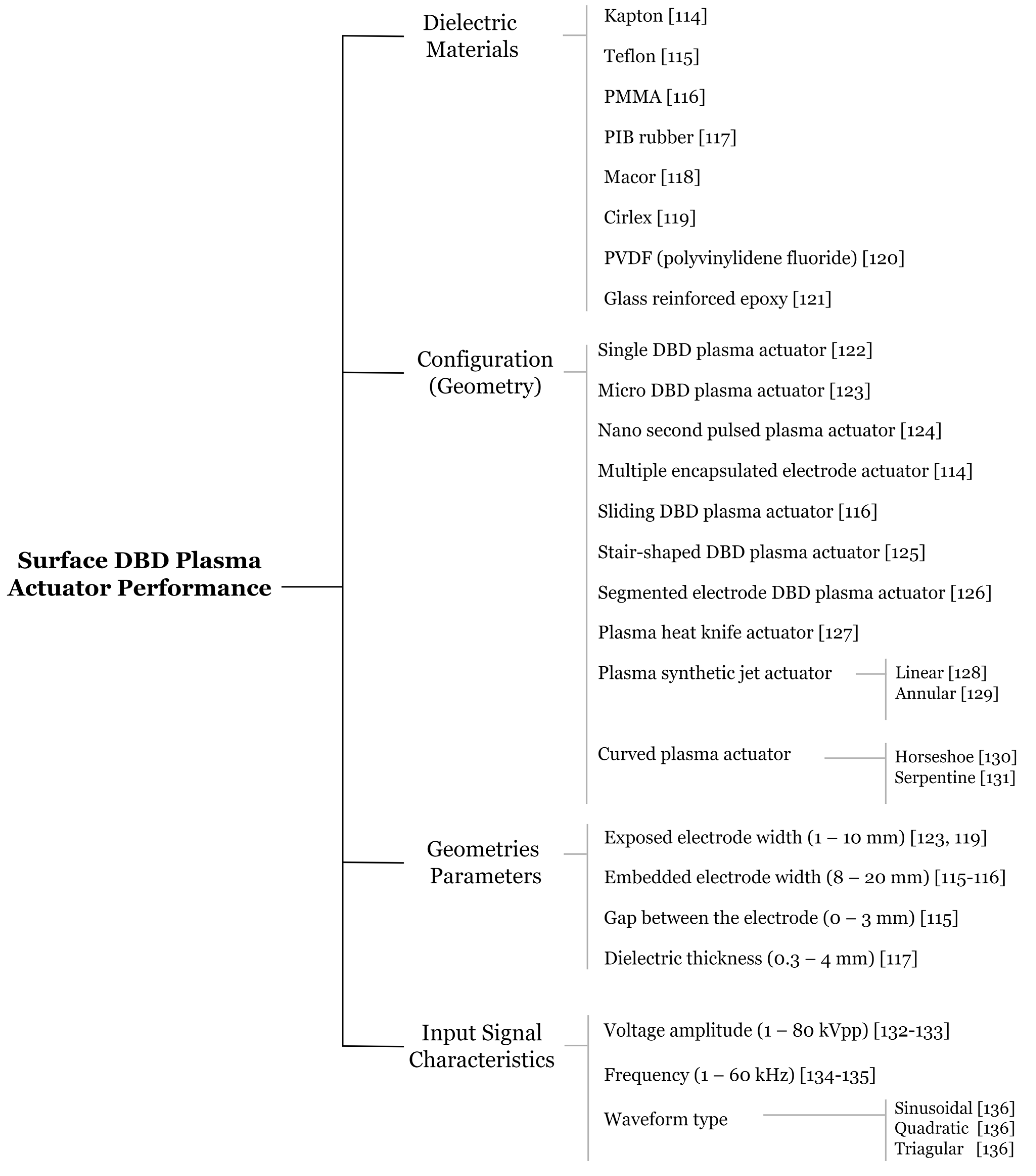
4.1. DBD Actuator Classification System

Based on the described general working principle of the DBD mechanism, as well as the different existing applications, dielectric barrier discharge designs may be divided into two main categories. It is noteworthy that the classification of configurations is distinguished by the presence and usage of the insulating material in the discharge path [102,106].
  • If the space between the electrodes includes both a dielectric and discharge gap, the plasma is therefore ignited in the volume existing between the two electrodes. In that case, the DBD is considered a volume dielectric barrier discharge, or VDBD geometry.
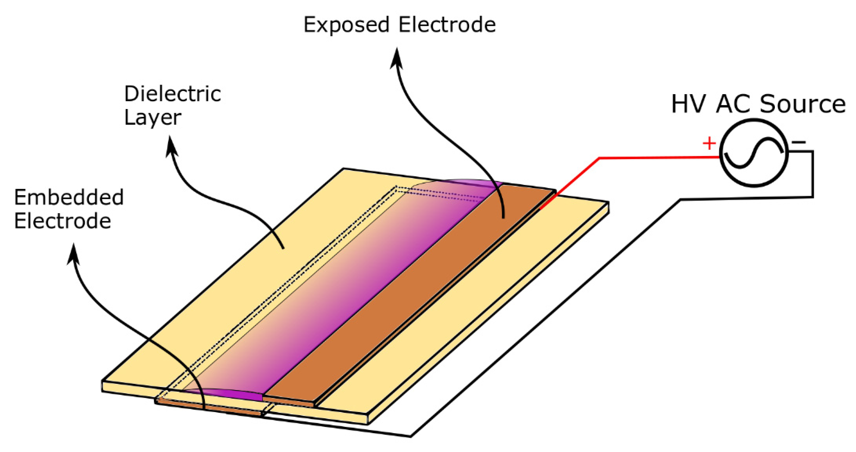
  • Otherwise, if the space between the electrodes is completely filled by a dielectric, the plasma is consequently ignited on the surface of the dielectric exposed to the gas volume. In that case, the DBD is named a surface dielectric barrier discharge, or SDBD geometry.
It is important to highlight that SDBDs, as shown in Figure 6, have been considered for space applications for decades. Since the 1990s, surface dielectric barrier discharge actuators—which are non-equilibrium plasma devices capable of generating forces in air without any moving parts—have been considered an engaging technology in the aerospace sector.
In 1993, Roth et al. disclosed methods and an apparatus for generating low-power density glow discharge plasmas at atmospheric pressure. To generate the plasma discharge, the inventors used a pair of electrically insulated metal plate electrodes mounted face-to-face in parallel or uniformly spaced alignments covered with dielectric insulation. Although this invention considered an arrangement similar to the conventional plasma actuator configuration, it did not disclose the possibility of performing active flow control operations [137].
Only in 2004, Enloe et al. disclosed the conventional plasma actuator configuration and explained that this device enabled partial ionization of gases using one or more electrode pairs, each having one electrically encapsulated electrode and one air stream exposed electrode that was energized by a high-voltage alternating current waveform. They also mentioned that this invention was particularly appropriate for use in airfoils for aerodynamic purposes, such as drag reduction, stall elimination, and airfoil efficiency improvement [138].
Overall, the engaging features of DBDs, such as their mechanical simplicity, light weight, planar and low drag-structure, as well as relatively low-performance power level consumption make them a great choice for, for example, aerodynamic flow control and aircraft propulsion investigations [113]. It is noted that various adaptations of DBDs to different problems have directed this technology towards the adoption of several special configurations. Just to name a few, DBD-based plasma jet actuators, multiple encapsulated electrode plasma actuators, nanosecond-DBD (i.e., NS-DBD), sliding discharges, and capillary plasma electrode discharges have been demonstrated and applied in numerous studies over the last few years, with special focus on aeronautical and aerospace purposes [102,139].

4.2. DBD Technology in Aerospace and Aeronautical Sectors

The origin of the dielectric barrier discharge is attributed to Ernst Werner von Siemens in 1857 [101,102,103,112]. The first experimental investigations performed by Siemens et al. [140] were focused on the generation of ozone and the experiment discharge apparatus design featured many novel traits, including electrodes positioned outside the discharge chamber that were not in contact with the plasma. For this reason, DBDs were considered ozone discharges for a long time [101,103,112,141]. In 1860, Andrew and Tait [142] named the system silent discharge because of its quiet and silent discharge process. Such nomenclature is still frequently used in English, German, and French scientific literature [101,103,141]. Later, K. Buss [143] made a notable contribution to characterizing the discharge in 1932 by reporting that the breakdown of atmospheric pressure air between the planar parallel electrodes covered by dielectrics always gave origin to a large number of tiny short-lived current channels. The first photographic traces—Lichtenberg figures—of these channels (or microdischarges) and oscilloscope recordings of current, in addition to the voltage applied, were obtained [103,112]. Further investigation of channels (or filaments) in more detail was conducted by several research groups, including Klemenc et al. (1937) [144], Suzuki (1950) [145], Honda and Naito (1955) [146], and later by Gobrecht et al. (1964) [147], Bagirov et al. (1971) [148], Tanaka et al. (1978) [149], Hirth (1981) [150] and Heuser (1984) [151]. Despite the ongoing research through the years, another key contribution was made by T.C. Manley in 1943 [152] who proposed a method for determining the dissipated power in DBDs using closed voltage/charge Lissajous figures and derived an equation that became known as the power formula for ozonizers [102,141].
Over the last years, plasma actuators based on the dielectric barrier discharge mechanism have attracted much attention for aerospace and aeronautical applications [153]. Broadly speaking, DBD actuators may be applied in research investigating aerodynamic active flow control and heat transfer [139].

4.3. Plasma Actuators for Aerodynamic Flow Control and Drag Reduction

Active flow control is an important subject of study since it allows for improving the efficiency of several mechanical systems by enhancing their performance through both fuel consumption and environmental impact reduction [154,155]. Thus, the ability to manipulate a flow field is crucial for the scientific community worldwide. In particular, dielectric barrier discharge plasma actuators are a technology with great characteristics for this aim, since it is characterized by easy implementation (i.e., simple construction), absence of moving parts, extremely low mass, robustness, low power requirements, and fast response to electrical signals [154,155,156,157]. From a practical point of view, this type of actuator allows modification of the airflow owing to the electrokinetic conversion mechanism, which is called the electrohydrodynamic (EHD) phenomenon. The exploited electrohydrodynamic force originating from the electrohydrodynamic phenomenon is produced due to momentum transfer from charged species accelerated by an electrical field to neutral molecules by collision [154,155]. On the whole, research regarding plasma actuators for active flow control includes turbulent boundary-layer separation control, steady airfoil leading-edge separation control, oscillating airfoil dynamic stall control, and circular cylinder wake control [154].

4.4. Plasma Actuators for Heat Transfer

Apart from the main described aerodynamic applications, dielectric barrier discharge plasma actuator devices can be considered and used within the field of heat transfer, for example, for film cooling of gas turbine blades and heat generation for de-icing or anti-icing objectives [157,158]. In essence, the thermal behavior of DBD plasma actuators has great importance for these types of applications. Nevertheless, there have been a relatively limited number of studies reporting these applications [158]. The concept of using plasma actuators for active flow control in the case of film cooling enhancement was introduced by Roy and Wang in 2008 [159], and it was shown by numerical simulations that the application of plasma discharges could improve the film cooling efficiency up to 26% [139,160]. Other studies were conducted over the years; however, the general conclusion is the same: despite different boundary conditions or geometries of components to be cooled, plasma aerodynamic actuation improves the overall efficiency of the film cooling process by enhancing the adherence of the coolant working fluid (also called “coolant jet”) [139,161]. Lastly, and regarding the application of plasma actuators in aircraft icing mitigation, Van den Broecke [162] was the first to conduct research on the feasibility and effectiveness of using DBD plasma actuators to remove ice accretion from a stationary flat plate. Currently, more studies have been carried out on this topic and plasma actuation has gained great attention concerning icing mitigation due to its unique features [163,164]. SDBD was described by Jia et al. (2022) [165] as a “novel anti-icing method featuring low energy consumption, geometrical simplicity, and rapid heating effect” and both nanosecond pulse SDBD (nSDBD) and alternating-current SDBD (AC-SDBD), depending on the driving waveform, have been verified through experiments for anti-icing purposes.

4.5. Ceramic Materials for DBD Systems

The performance of DBD plasma actuators may be predominantly considered in terms of their three major features, i.e., their electrical parameters, the geometry chosen, and the material properties of particular interest (dielectric barrier materials). Despite the several advantageous features of DBD plasma actuators, one of the major weaknesses of these devices is their longevity.
Moreau (2007) [166], Corke et al. (2009) [167], and Bernard and Moreau (2014) [168] have elaborated comprehensive reviews of the physics, modeling, experiments, and applications of plasma actuators [169,170]. In addition, the properties of dielectric materials have been described by Bian et al. (2017) [170] and Rodrigues (2019) [139]. For instance, parameters such as dielectric thickness and its influence on DBD plasma actuator performance, the relationship between the concentration of discharge filaments and the consequent dielectric breakdown, as well as the surface temperature of the dielectric and its impact on the transition from glow to filamentary discharge have all been addressed. Furthermore, both novel dielectric barrier materials and material modifications, focusing mainly on polymers—due to their simplicity of use—have also been part of the current research regarding DBD devices [167]. Nevertheless, polymers have been reported to be very vulnerable to ion bombardment, radical species, and ultraviolet radiation emitted by plasma filaments in air at atmospheric pressure, thus making them extremely susceptible to material degradation [139,171].
As a result, ceramics appear to be a suitable substitute for the widely used polymers, since this type of material offers several superior and favorable traits, such as corrosion resistance, high- and low-temperature resistance, excellent dielectric properties, and heat conduction—which clearly highlights the possibility of ceramics being a good dielectric barrier in the years to come [170]. In spite of today’s advancements in many technical and scientific fields, extensive research exploring dielectric barrier layers in standard applications of dielectric barrier discharge is lacking in the literature [172]. This is particularly concerning since physical properties and plasma-chemical efforts are highly dependent on the material of the dielectric barrier. In other words, both surface and electrical properties of the DBD actuator are particularly influenced by the chemical composition of the dielectric barrier. These features are of utmost importance since they affect charge accumulation, charge traps, and electric field distribution in the vicinity of the dielectric surface [173,174].
In an attempt to emphasize the most prominent investigations on dielectric barrier materials found in the literature, some studies will be summarized below.
Pons et al. (2008) [171] analyzed the surface degradation of two types of polymers as a dielectric barrier on a DBD actuator, i.e., polymethyl methacrylate (PMMA) and polyvinyl chloride (PVC) materials, and compared them with borosilicate glass. Images captured of both polymers showed clear degradation after operation in terms of roughness and burning, as well as color changing. Contrary to the evaluated polymers, images captured of borosilicate glass plates presented no obvious modification of the surface. It was concluded that this material is indeed more robust to chemical and radiation exposure.
Silica glass (ceramic) dielectric barriers have been successfully utilized in many DBD experiments and have demonstrated improved resilience over organic materials, including epoxies and polyimide film (Kapton tape) [170,175]. Zito et al. (2013) [175] fabricated microscale dielectric barrier discharge plasma actuators and experimentally characterized silicon dioxide for the dielectric barrier. It was stated that by using SiO2 as a dielectric barrier, the lifetime of the actuators was extended when compared with the first generation of DBD actuators, i.e., polymer dielectric material. Furthermore, Fine and Brickner (2010) [176] proposed the addition of a heterogeneous catalyst on the surface of the dielectric exposed to the plasma as an approach to increase actuator thrust. It was reported, according to the results obtained, that the use of titania (TiO2) as a plasma catalyst increased the actuator thrust by 120% compared to a catalyst-free actuator.
In addition, in order to determine the time-resolved body force induced by a DBD plasma actuator and a correlation between induced body force, flow behavior, and phase of the dielectric discharge, Neumann et al. (2012) [177] performed flow studies captured with high spatial and temporal resolution. A ceramic dielectric manufactured using low temperature co-fired ceramics technology (LTCC) was applied which, according to the authors, allowed the use of a very durable and lasting ceramic, possibly enabling the future application of this material in harsh environments, such as turbomachines. In turn, Segawa et al. (2007) [128] reported the characteristics of a DBD actuator under elevated temperatures—up to 600 °C. In their study, the authors developed a DBD plasma actuator with ceramic and quartz insulators and verified the performance deterioration with increasing temperature.
On top of all the investigations described, to obtain a homogeneous DBD in air at atmospheric pressure, many methods—including different types of barrier materials, power supply, and electrode arrangements—have been explored [178].
Ran et al. (2018) [178] focused their work on the factors that influence the formation of homogeneous discharges at atmospheric pressure in air with a greater focus on dielectric properties on discharge modes. The experimental set-up featured plane-parallel electrodes which were covered with quartz plates of 0.5 to 1 mm thick or Al2O3 ceramic plates of 0.5 to 3.25 mm thick. It was found that the dielectrics played a crucial role in the formation of atmospheric pressure Townsend discharge (APTD) in the open air. Briefly, the Townsend discharge consists of a gas ionization process where an initially small amount of free electrons, accelerated by a sufficiently strong electric field, gives rise to electrical conduction through a gas by avalanche multiplication. Once the number of free charges drops or the electric field weakens, the phenomenon ceases [179]. Three dielectric characteristics were distinguished of major importance: type of dielectric material, thickness of the dielectric barrier, and surface roughness of the dielectric barrier. Nevertheless, it was highlighted by the authors that the rougher the dielectric material, the greater number of shallow traps, so more electrons can be provided for the next half-cycle discharge of the DBD. In addition, it was shown that the surface roughness of the dielectric also reduced the breakdown electric field due to its uneven surface. The ceramics used in this study had more shallow traps than quartz glass, which explained the difficulties quartz has in generating homogeneous DBD in air.
As a follow-up, Ran et al. (2020) [180] approached the factors that affect the transition of discharge mode for obtaining a homogeneous atmospheric pressure discharge in air. The surface morphology of different dielectric materials—quartz glass and ceramic—was given special attention. Once again, it was concluded that the surface morphology of different applied dielectrics has a remarkable influence on the discharge mode and emission spectrum of the discharge.
Particularly interesting about DBD actuators is the efficiency of the DBD plasma chemical reaction. In fact, this efficiency is expected to increase by increasing the permittivity of the barrier material, since the transported charge of the plasma reaction is proportional to the permittivity of the dielectric material. Ceramics with high permittivity tend to break by supplying a high voltage thanks to their modest dielectric strength, and therefore SiO2, which has a low permittivity, is generally used as a dielectric material [181]. Nevertheless, MTiO3 (M = Ca, Sr, Ba) ceramics are actually recognized as a typical dielectric material possessing a variety of dielectric properties. Li et al. (2004) [181] investigated the sinterability and mechanical and dielectric properties of Ca0.7Sr0.3TiO3 using Li2Si2O5 as a sintering additive. The produced ceramic was applied as a dielectric barrier for the decomposition of CO2. For comparison purposes, alumina and silica glass were also used as dielectric barriers. The results indicated that the permittivities of the three types of ceramics at 100 °C and 10 MHz were in the order of Ca0.7Sr0.3TiO3 (207) >> alumina (10.4) > silica glass (4.6); and the CO2 conversions greatly changed depending on the barrier materials in the same order as the permittivity, i.e., Ca0.7Sr0.3TiO3 >> alumina > silica glass.
In the same train of thought, Song et al. (2016) [174] evaluated the performance of Ca0.8Sr0.2TiO3 ceramics as a dielectric barrier, based on different amounts of glass addition, in the decomposition of carbon dioxide at atmospheric pressure. Several conclusions were reached, including the feasibility of using Ca0.8Sr0.2TiO3 for the decomposition of CO2, since both the conversion rate and efficiency increased with increasing glass content.
Moreover, the literature states that alumina ceramics are widely applied as ceramic dielectric barriers, since they are considered sufficient for DBD actuator applications due to their advantageous features, such as high mechanical and dielectric strength, high resistivity, and small dielectric losses [173]. Regarding the influence of the DBD actuator above the construction threshold on the two-dimensional subsonic boundary layer, Moralev et al. (2018) [182] used an actuator design with a two-layer underlying electrode to stabilize the position of the filaments and 1 mm thick dielectric plates of alumina ceramic were placed between these two electrode layers, as well as above them. Recently, Kelar et al. (2020) [173] determined the ignition and quenching voltage of the DBD regarding the effect of adding several types of oxides to a pure alumina ceramic. The aim was to determine the impact of the chemical composition of the dielectric barrier. Overall, the final findings showed that the addition of small amounts of oxide dopant into pure alumina ceramic affected both the chemical composition and surface structure of the ceramic, which in turn influenced the plasma parameters. Similarly, the work carried out by Pribyl et al. (2020) [173] consisted of a complex study on alumina-based ceramic barriers doped with spinel, i.e., MgAl2O4. It was concluded that the change in the sample composition resulted in a nonlinear response of the physical properties for coplanar DBD (CDBD). It was remarked that the determination of bulk and surface properties is necessary for complex analysis of the suitability of materials for use as a dielectric barrier for CDBD; however, based on the knowledge and experience already acquired, alumina-based ceramics with a small addition of MgAl2O4 are promising materials for effective cold nonthermal plasma generation.
Lastly, a remarkable investigation was carried out by Bian et al. (2017) [170] in which the material characterization and performance evolution of an AlN ceramic-based DBD plasma actuator was reported. A conventional Al2O3 ceramic was also investigated as a control. Many conclusions were extrapolated, but, in general, the authors highlighted that the AlN-based actuator produced a more uniform discharge whilst the discharge of the Al2O3 actuator easily became filamentary. The latter condition unfortunately leads to higher power consumption and earlier failure due to electrode oxidation.

5. Multifunctional Advanced Ceramics

The function of an engineered ceramic material may be defined as the specific purpose for which it is used in a particular application. Moreover, multifunctional ceramic systems composed of different materials—each offering primarily a single function—are well known. Nevertheless, sometimes even for a monofunctional application, a fine ceramic is frequently able to fulfill a set of secondary purposes based on their secondary properties [183]. Taking into consideration the three aforementioned and reviewed applications of advanced ceramics in aerospace and aeronautical engineering fields, i.e., thermal protection systems, thermal barrier coatings, and dielectric barrier discharges—Figure 7, in addition to the materials assessed in each subsection, the following three chemical compositions of ceramic systems carefully studied follows: MgO-doped aluminum oxide, MgO-doped calcium zirconate oxide, and yttria-stabilized zirconia.

5.1. MgO-Doped Aluminum Oxide

Aluminum oxide, commonly referred to as alumina, is one of the most widely used, cost-effective materials in the family of fine ceramics. With an excellent combination of properties and reasonably priced, available raw materials, fine-grain technical alumina has a very wide range of applications. In detail, this material possesses strong ionic interatomic bonding, which consequently gives rise to its desirable key properties, such as:
  • high-temperature stability,
  • excellent size and shape molding capabilities,
  • high strength, stiffness, hardness, and wear resistance,
  • good corrosion and erosion resistance,
  • resistant to strong acid and alkali attacks at elevated temperatures,
  • high dielectric strength and small dielectric losses, and
  • commercial availability in purity ranges from 94% to 99.8% for the most demanding high-temperature applications.
Moreover, the listed characteristics make alumina-based ceramics the material of choice for a wide range of applications, including high temperature and aggressive environments, wear and corrosion resistance, metal cutting tools, microwave components, and electrical insulation.
Furthermore, authors such as Pribyl et al. [173], Mollá et al. [184], and Ramírez González et al. [185] evaluated the addition of magnesium-based dopants in standard alumina ceramics. It was reported and highlighted that Mg-based dopant components are usually used as a sintering aid in the alumina fabrication process since they inhibit grain growth and increase the final density of the material. Accordingly, and bearing in mind two crucial considerations described in Section 2.1 and Section 2.3, respectively, that (a) oxide ceramics are intuitively good candidates for passive TPS application, (b) alumina is a state-of-the-art ceramic dielectric barrier material of DBD actuators.
From the TBC point of view, alumina oxide is a very stable phase with very high hardness and chemical inertness. However, the plasma-sprayed coating of alumina contains mainly unstable phases, such as gamma- and delta-Al2O3. These unstable phases will transform into alfa-Al2O3 during thermal cycling, accompanied by a significant volume change (≈15%), which results in microcrack formation in the coating [67,186,187].
Nevertheless, in hexaaluminates, MgO played an important role in recrystallization and grain growth rates that promote coatings with improved properties, such as reduced microhardness, greater strain tolerance and thermal shock resistance, as well as better CTE, as described by Chen et al. (2011) [98]. The MgO-doped alumina increased the densification and grain size reduction, thus improving the mechanical properties of the alumina coating, such as coating hardness and substrate oxidation resistance. Furthermore, the formation of MgAl2O4 spinel phase can promote cracking-healing behavior within the coating [188].

5.2. MgO-Doped Calcium Zirconate Oxide

Calcium zirconate oxide, also named calcium zirconate (CZ), is reported to be a potential candidate for many purposes in mechanical, coating, and electrical applications. As described in Section 2.2, calcium zirconate has appealing and exciting thermal properties, rendering this ceramic material a convenient candidate for thermal barrier applications. In addition, CZ is a material with a perovskite structure that is of fundamental significance for its electrical properties. All in all, some of the attractive properties of calcium zirconate oxide include:
  • excellent mechanical properties,
  • low thermal conductivity,
  • high thermal and chemical stabilities,
  • good thermal shock resistance,
  • high melting point, and
  • excellent dielectric properties, i.e., high dielectric constant, low loss factor, and both of qualities are stable between 1 kHz and 1 MHz.
Calcium zirconate has been applied in different sectors, for example, as a sensor material in aluminum melts, refractory material for titanium metallurgy, and microwave dielectric ceramic in modern communication systems. Nonetheless, it is considered to be an alternative material to YSZ in thermal barrier coatings in aeronautical and aerospace fields, as pointed out by Ma et al. [82], Garcia. et al. [83], and explained in Section 4.4 (perovskites).
Additionally, the literature indicates that simple perovskite structure materials are of essential significance for their electrical properties, including ferroelectricity, piezoelectricity, and superconductivity. Studies showed that perovskite ceramics increased the efficiency of the dielectric barrier discharge process. Li et al. [181] and Song et al. [174] focused their studies on the family of CaTiO3-based compositions, however, these ceramics had the drawback of lower temperature stability when compared to CaZrO3.
In the literature, studies proposing CaZrO3 for TPS are limited; however, in some previous works [189,190,191,192,193], research was carried out on the behavior, mechanical properties (flexural resistance, compression, wear, hardness, and toughness), and thermomechanical characteristics (diffusivity, heat transfer, thermal conductivity, and CTE) of the CaZrO3–MgO system, showing that it is a valid option for structural applications at high temperatures.
Taking the above aspects into account and the densification and inhibition of grain growth during the sintering process, the MgO-doped CaZrO3 ceramic system is also considered to be a reasonable and suitable material for TPS, TBC, and DBD applications.

5.3. Yttria-Stabilized Zirconia

As described in Section 4.2 (Ceramic Materials for TBC Systems), yttria-stabilized zirconia has been widely considered and adopted for thermal barrier coatings on gas turbine blades typically made of a Ni-based superalloy because of its attractive properties, such as high thermal stability, low thermal conductivity, and a relatively large thermal expansion coefficient, which is close to that of the metal substrate. In addition, it is known that zirconia or ZrO2 has a very high melting point (3053 K), as well as high-temperature, wear, and corrosion resistance. Nonetheless, pure zirconium dioxide undergoes a phase transformation from monoclinic (stable at room temperature) to tetragonal (at approximately 1170 °C) and then to cubic (at about 2370 °C). Therefore, in order to obtain stable zirconia ceramic products, stabilized zirconia has been developed and studied by doping ZrO2. Particularly, by adding yttrium oxide or yttria (Y2O3), which has excellent chemical inertness and high corrosion resistance, it is possible to obtain a fully stabilized zirconia. Precisely, ZrO2 with 7–8 wt.% Y2O3 composition has been studied for years for TBC applications due to its unique properties enumerated in Section 3 on Thermal Barrier Coatings, and enumerated once again:
  • very high mechanical strength and wear resistance,
  • very high erosion resistance,
  • high impact resistance,
  • high corrosion resistance,
  • high chemical resistance,
  • very low thermal conductivity, and
  • relatively high coefficient of thermal expansion when compared to other ceramics.
Recent MSc work by Balça (2021) [194] specifically studied the optimization of multiphase composites of zirconium oxide for thermomechanical aeronautical applications by applying DoE analysis. On the whole, the research consisted of the fabrication and microstructural, physical, mechanical, and thermal characterization of seven multiphase distinct ceramic compositions in which pure (monoclinic phase, mZ), tetragonal phase (3YSZ, tZ), and cubic (8YSZ, cZ) zirconias served as the base materials. After performing a DoE study, the composition (wt.%) of 1:3 cZr, 1:3 tZ, and 1:3 cZ (1:3 all YSZ) was selected, based on the mechanical and thermal results, as the best fit for a thermal barrier coating and passive thermal protection system.
It is important to emphasize that the choice was mainly influenced by the material’s high mechanical resistance and notably low thermal conductivity, which is a crucial parameter for the two applications referred. To sum up, Figure 8 outlines the three ceramic systems chosen to be investigated, i.e., MgO-doped Al2O3, MgO-doped CaZrO3, and 1:3 of all yttria-stabilized zirconia, in addition to their intended applications based on the aeronautical and aerospace implementations exploited (TPS, TBC, and DBD) illustrated in Figure 7.
The selections were made in the sense that, when possible, one of the functions of each candidate ceramic system should be based on their usual state-of-the-art application. For example, yttria-stabilized zirconia is a state-of-the-art material for TBCs, whereas alumina ceramic is used for DBD. The second application should be an alternative application according to the literature reviewed. The third and remaining application, which is always opposite to the material considered in the diagram, serves as a suggestion and, therefore, further studies are expected to determine its suitability, such as MgO-doped calcium zirconate as a TPS, MgO-doped alumina for TBC usage, and lastly, yttria-stabilized zirconia as a dielectric barrier for DBD actuators.

6. Conclusions

The premise that materials permeate the technological innovations that contribute to our social well-being and impact our daily lives is well accepted, so we have two major challenges: (i) increase energy savings and consequently increase the energy efficiency and durability of products; (ii) access more economical and local raw materials, thus minimizing transport and geopolitical constraints. Therefore, continuous research and enhancing our understanding of materials allow us to optimize new products by improving existing materials, adapting them to new manufacturing processes, and developing new functions for them. Hence, novel opportunities arise. Advanced ceramics can be designed to add value to forms of current manufacturing and may provide innovative alternative solutions to current problems.
This review presents solutions with multifunctional ceramic composites for fundamental applications in aerospace and aeronautics, including thermal protection systems (TPS) and thermal barrier coatings (TBC). In this context, TPS and TBC are mature systems with valid industrial solutions. However, new proposals and solutions are welcome with the objective of improving energy efficiency and increasing durability. The integration of new functionalities, such as dielectric barrier discharge (DBD) requires the use of reliable ceramic composites with predictable properties and well-known manufacturing processes that allow their adaptation to new designs and specifics.
Thus, the proposed ceramic composites are valid solutions for some functions and still little known for other uses. For example, MgO-doped aluminum oxide is proposed for passive TPS application and in dielectric barrier discharge; however, like TBC, there are other alternatives. Nevertheless, their application in view of a multifunctional response is a potential solution. The ceramic MgO-doped CaZrO3 system used in TBC is a good candidate for DBD due to its electrical properties, and its proposed use in TPS is a reliable solution. Yttria-stabilized zirconia (YSZ) is a widely adopted material for TBC and TPS functions. The proposal of mixing zirconias (1:3 monoclinic, 1:3 tetragonal, and 1:3 cubic phases) as a base ceramic composite may enhance thermal barrier coatings and passive thermal protection system applications. The multiphase microstructure of this ceramic creates the fundamental electrical potential for DBD function.

Author Contributions

Conceptualization, J.N.-P., F.F.R. and A.P.S.; investigation, K.O.S.; Writing—Original draft preparation, K.O.S.; Writing—Review and editing, J.N.-P., F.F.R. and A.P.S.; Supervision, J.N.-P., F.F.R. and A.P.S.; Project administration, A.P.S.; Funding acquisition, A.P.S. All authors have read and agreed to the published version of the manuscript.

Funding

This work was supported by the following projects and organisms: Portuguese Foundation for Science and Technology, I.P. (FCT, I.P.) FCT/MCTES through national funds (PIDDAC), under the R&D Unit C-MAST/Center for Mechanical and Aerospace Science and Technologies (Project UIDB/00151/2020) and under the R&D Unit CF-UM-UP/Centro de Física das Universidades do Minho e do Porto (Project UID/FIS/04650/2020). JNP also thanks FCT, I.P., European Social Fund (ESF), European Union (EU), and Regional Operational Programme Centro 2020 and Norte 2020 for the grant SFRH/BPD/117838/2016.

Data Availability Statement

Not applicable.

Acknowledgments

Portuguese Foundation for Science and Technology, I.P. (FCT, I.P.) FCT/MCTES through national funds (PIDDAC), under the R&D Unit C-MAST/Center for Mechanical and Aerospace Science and Technologies (Project UIDB/00151/2020) and under the R&D Unit CF-UM-UP/Centro de Física das Universidades do Minho e do Porto (Project UID/FIS/04650/2020). JNP also thanks FCT, I.P., European Social Fund (ESF), European Union (EU), and Regional Operational Programme Centro 2020 and Norte 2020 for the grant SFRH/BPD/117838/2016.

Conflicts of Interest

The authors declare no conflict of interest. The funders had no role in the design of the study; in the collection, analyses, or interpretation of data; in the writing of the manuscript; or in the decision to publish the results.

References

  1. Heimann, R.B. Preface. In Classic and Advanced Ceramics: From Fundamentals to Applications; Wiley-VHC: Darmstad, Germany, 2010; pp. XV–XIX. [Google Scholar]
  2. EDA Technology Watch & Foresight. Available online: https://eda.europa.eu/what-we-do/research-technology/technology-watch-foresight (accessed on 13 October 2022).
  3. Rödel, J.; Kounga, A.B.; Weissenberger-Eibl, M.; Koch, D.; Bierwisch, A.; Rossner, W.; Hoffmann, M.J.; Danzer, R.; Schneider, G. Development of a roadmap for advanced ceramics: 2010–2025. J. Eur. Ceram. Soc. 2009, 29, 1549–1560. [Google Scholar] [CrossRef]
  4. Singh, K.; Kaur, M.; Kumar, A. Progress in Advanced Ceramnics: Energy and Environmental Perspective. In Advanced Ceramics for Energy and Environmental Applications; Kumar, A., Ed.; CRC Press: Boca Raton, FL, USA, 2013; pp. 1–12. [Google Scholar]
  5. Advanced Ceramics—The Evolution, Classification, Properties, Production, Firing, Finishing and Design of Advanced Ceramics. Available online: https://www.azom.com/article.aspx?ArticleID=2123 (accessed on 13 October 2022).
  6. Ceramics and Glass in the Aerospace Industry. Available online: https://ceramics.org/about/what-are-engineered-ceramics-and-glass/ceramics-and-glass-in-the-aerospace-industry (accessed on 13 October 2022).
  7. Soboyejo, W.O.; Obayemi, J.; Annan, E.; Ampaw, E.; Daniels, L.; Rahbar, N. Review of High Temperature Ceramics for Aerospace Applications. Adv. Mater. Res. 2015, 1132, 385–407. [Google Scholar]
  8. Riccio, A.; Raimondo, F.; Sellitto, A.; Carandente, V.; Scigliano, R.; Tescione, D. Optimum design of ablative thermal protection systems for atmospheric entry vehicles. Appl. Therm. Eng. 2017, 119, 541–552. [Google Scholar] [CrossRef]
  9. Zarko, V.E. The Prospects of Using Nanoenergetic Materials in Solid Rocket Propulsion. In Nanomaterials in Rocket Propulsion Systems; Yan, Q.-L., He, G.-Q., Liu, P.-J., Gozin, M., Eds.; Elsevier: Amsterdan, The Netherlands, 2019; pp. 3–30. [Google Scholar] [CrossRef]
  10. Venkatapathy, E.; Szalai, C.E.; Laub, B.; Hwang, H.H.; Conley, J.L.; Arnold, J.; Arc, N. Thermal Protection System Technologies for Enabling Future Sample Return Missions NASA. 2009. Available online: https://ia600503.us.archive.org/5/items/ThermalProtectionSystemTechnologiesforEnablingFutureSampleReturnMissions/111_nasaArc_venkatapathy_tps_sampleReturn.pdf (accessed on 13 October 2022).
  11. Uyanna, O.; Najafi, H. Thermal protection systems for space vehicles: A review on technology development, current challenges and future prospects. Acta Astronaut. 2020, 176, 341–356. [Google Scholar] [CrossRef]
  12. Roger, D.L.; Jenkins, D.R. Coming home: Reentry and recovery from space (NASA SP-2011-593). NASA. 2012. Available online: https://www.nasa.gov/sites/default/files/695726main_ComingHome-ebook.pdf (accessed on 13 October 2022).
  13. Ortona, A.; Badini, C.; Liedtke, V.; Wilhelmi, C.; D’Angelo, C.; Gaia, D.; Fischer, W. Hetoroporous heterogeneous ceramics for reusable thermal protection systems. J. Mater. Res. 2013, 28, 2273–2280. [Google Scholar] [CrossRef]
  14. Glass, D. Ceramic Matrix Composite (CMC) Thermal Protection Systems (TPS) and Hot Structures for Hypersonic Vehicles. In Proceedings of the 15th AIAA International Space Planes and Hypersonic Systems and Technologies Conference, Dayton, OH, USA, 28 April–1 May 2008. [Google Scholar]
  15. Sziroczak, D.; Smith, H. A review of design issues specific to hypersonic flight vehicles. Prog. Aerosp. Sci. 2016, 84, 1–28. [Google Scholar] [CrossRef] [Green Version]
  16. Zhu, Y.; Peng, W.; Xu, R.; Jiang, P. Review on active thermal protection and its heat transfer for airbreathing hypersonic vehicles. Chin. J. Aeronaut. 2018, 31, 1929–1953. [Google Scholar] [CrossRef]
  17. Harpale, A.; Sawant, S.; Kumar, R.; Levin, D.; Chew, H.B. Ablative thermal protection systems: Pyrolysis modeling by scale-bridging molecular dynamics. Carbon 2018, 130, 315–324. [Google Scholar] [CrossRef]
  18. Laub, B.; Venkatapathy, E. Thermal protection system technology and facility needs for demanding future planetary missions. In Proceedings of the International Workshop Planetary Probe Atmospheric Entry and Descent Trajectory Analysis and Science, Lisbon, Portugal, 6–9 October 2003; Available online: https://ui.adsabs.harvard.edu/abs/2004ESASP.544.239L/abstract (accessed on 13 October 2022).
  19. Meseguer, J.; Perez-Grande, I.; Sanzx-Andrés, A. Spacecraft Thermal Control; Woodhead Publishing: Cambridge, UK, 2012. [Google Scholar]
  20. Natali, M.; Kenny, J.M.; Torre, L. Science and technology of polymeric ablative materials for thermal protection systems and propulsion devices: A review. Prog. Mater. Sci. 2016, 84, 192–275. [Google Scholar] [CrossRef]
  21. Johnson, S.M. Thermal protection materials and systems: An overview. In Engineered Ceramics: Current Status and Future Prospects; Ohji, T., Singh, M., Eds.; John Wiley & Sons, Inc.: Hoboken, NJ, USA, 2015; pp. 224–246. [Google Scholar]
  22. Sengupta, P.; Manna, I. Advanced High-Temperature Structural Materials for Aerospace and Power Sectors: A Critical Review. Trans. Indian Inst. Met. 2019, 72, 2043–2059. [Google Scholar] [CrossRef]
  23. Padture, N. Advanced structural ceramics in aerospace propulsion. Nat. Mater. 2016, 15, 804–809. [Google Scholar] [CrossRef] [PubMed]
  24. Claub, B. Fiber for Ceramic Matrix Composites. In Ceramic Matrix Composites: Fiber Reinforced Ceramics and Their Applications; Krenkel, W., Ed.; John Wiley & Sons: Weinheim, Germany, 2008; pp. 1–20. [Google Scholar]
  25. Naslain, R.R.; Pomeroy, M.R. Ceramic Matrix Composites: Matrices and Processing. In Reference Module in Materials Science and Materials Engineering; Elsevier: Amsterdam, The Netherlands, 2001. [Google Scholar] [CrossRef]
  26. Donald, I.W.; McMillan, P.W. Ceramic-matrix composites. J. Mater. Sci. 1976, 11, 949–972. [Google Scholar] [CrossRef]
  27. Cho, J.; Boccaccini, A.R.; Shaffer, M.S.P. Ceramic matrix composites containing carbon nanotubes. J. Mater. Sci. 2009, 44, 1934–1951. [Google Scholar] [CrossRef] [Green Version]
  28. Porwal, H.; Grasso, S.; Reece, M.J. Review of graphene–ceramic matrix composites. Adv. Appl. Ceram. 2013, 112, 443–454. [Google Scholar] [CrossRef]
  29. Wei, K.; Wang, K.; Cheng, X.; Peng, Y.; Li, M.; Yang, X. Structural and thermal analysis of integrated thermal protection systems with C/SiC composite cellular core sandwich panels. Appl. Therm. Eng. 2018, 131, 209–220. [Google Scholar] [CrossRef]
  30. Heidenreich, B.; Kraft, H.; Bamsey, N.; Such-Taboada, M. Shear properties of C/C-SiC sandwich structures. Int. J. Appl. Ceram. Technol. 2021, 19, 54–61. [Google Scholar] [CrossRef]
  31. Huang, J.; Guo, L. SiC coating with high crack resistance property for carbon/carbon composites. Ceram. Int. 2021, 48, 1740–1744. [Google Scholar] [CrossRef]
  32. Opila, E.; Levine, S.; Lorincz, J. Oxidation of ZrB2- and HfB2-based ultra-high temperature ceramics: Effect of Ta additions. J. Mater. Sci. 2004, 39, 5969–5977. [Google Scholar] [CrossRef]
  33. Chamberlain, A.; Fahrenholtz, W.; Hilmas, G.; Ellerby, D. Characterization of Zirconium Diboride for Thermal Protection Systems. Key Eng. Mater. 2004, 264, 493–496. [Google Scholar]
  34. Zhang, H.; Jayaseelan, D.; Bogomol, I.; Reece, M.; Hu, C.; Grasso, S.; Lee, W. A novel microstructural design to improve the oxidation resistance of ZrB2-SiC ultra-high temperature ceramics (UHTCs). J. Alloys Compd. 2019, 785, 958–964. [Google Scholar] [CrossRef]
  35. Ni, D.; Cheng, Y.; Zhang, J.; Liu, J.-X.; Zou, J.; Chen, B.; Wu, H.; Li, H.; Dong, S.; Han, J.; et al. Advances in ultra-high temperature ceramics, composites, and coatings. J. Adv. Ceram. 2021, 11, 1–56. [Google Scholar] [CrossRef]
  36. Sciti, D.; Silvestroni, L.; Monteverde, F.; Vinci, A.; Zoli, L. Introduction to H2020 project C3HARME—Next generation ceramic composites for combustion harsh environment and space. Adv. Appl. Ceram. 2018, 117, s70–s75. [Google Scholar] [CrossRef] [Green Version]
  37. Merrill, G.B.; Morrison, J.A. High Temperature Insulation for Ceramic Matrix Composites. U.S. Patent 6013592A, 11 January 2020. [Google Scholar]
  38. Merrill, G.B.; Jackson, T.B. Process for Applying a Thermal Barrier Coating to a Ceramic Matrix Composite. U.S. Patent US7648605B2, 19 January 2010. [Google Scholar]
  39. Zhu, D. Aerospace Ceramic Materials: Thermal, Environmental Barrier Coatings and SiC/SiC Ceramic Matrix Composites for Turbine Engine Applications; NASA: Washington, DC, USA, 2018. [Google Scholar]
  40. Zhu, D.; Lee, K.N.; Miller, R.A. Thermal Gradient Cyclic Behavior of a Thermal/Environmental Barrier Coating System on SiC/SiC Ceramic Matrix Composites. In Proceedings of the ASME Turbo Expo 2002: Power for Land, Sea, and Air, Amsterdam, The Netherlands, 3–6 June 2002. [Google Scholar] [CrossRef]
  41. Tang, S.; Hu, C. Design, Preparation and Properties of Carbon Fiber Reinforced Ultra-High Temperature Ceramic Composites for Aerospace Applications: A Review. J. Mater. Sci. Technol. 2017, 33, 117–130. [Google Scholar] [CrossRef]
  42. Arai, Y.; Inoue, R.; Goto, K.; Kogo, Y. Carbon fiber reinforced ultra-high temperature ceramic matrix composites: A review. Ceram. Int. 2019, 45, 14481–14489. [Google Scholar] [CrossRef]
  43. Mungiguerra, S.; Silvestroni, L.; Savino, R.; Zoli, L.; Esser, B.; Lagos, M.; Sciti, D. Qualification and reusability of long and short fibre-reinforced ultra-refractory composites for aerospace thermal protection systems. Corros. Sci. 2021, 195, 109955. [Google Scholar] [CrossRef]
  44. Kilic, M.; Ozkan, D.; Gok, M.S.; Karaoglanli, A.C. Room- and High-Temperature Wear Resistance of MCrAlY Coatings Deposited by Detonation Gun (D-Gun) and Supersonic Plasma Spraying (SSPS) Techniques. Coatings 2020, 10, 1107. [Google Scholar] [CrossRef]
  45. Ctibor, P. Interaction of Strontium Zirconate Plasma Sprayed Coating with Natural Silicate (CMAS) Dust—Origin of Luminescent Phases. Coatings 2020, 10, 738. [Google Scholar] [CrossRef]
  46. Song, D.; Song, T.; Paik, U.; Lyu, G.; Jung, Y.-G.; Choi, B.-G.; Kim, I.-S.; Zhang, J. Crack-Resistance Behavior of an Encapsulated, Healing Agent Embedded Buffer Layer on Self-Healing Thermal Barrier Coatings. Coatings 2019, 9, 358. [Google Scholar] [CrossRef] [Green Version]
  47. Mondal, K.; Nuñez, L.; Downey, C.M.; van Rooyen, I.J. Thermal Barrier Coatings Overview: Design, Manufacturing, and Applications in High-Temperature Industries. Ind. Eng. Chem. Res. 2021, 60, 6061–6077. [Google Scholar] [CrossRef]
  48. Liu, Q.; Huang, S.; He, A. Composite ceramics thermal barrier coatings of yttria stabilized zirconia for aero-engines. J. Mater. Sci. Technol. 2019, 35, 2814–2823. [Google Scholar] [CrossRef]
  49. Harrison, W.; Moore, D.; Richmond, J. Review of an Investigation of Ceramic Coatings for Metallic Turbine Parts and Other High-Temperature Applications; (Technical Note No. 1186); NACA: Boston, MA, USA, 1947; Available online: https://apps.dtic.mil/sti/pdfs/ADB807239.pdf (accessed on 13 October 2022).
  50. Miller, R.A. History of Thermal Barrier Coatings for Gas Turbine Engines: Emphasizing NASA’s Role from 1942 to 1990 (NASA/TM-2009-215459); NASA: Boston, MA, USA, 2009. Available online: https://ntrs.nasa.gov/api/citations/20090018047/downloads/20090018047.pdf (accessed on 13 October 2022).
  51. Miller, R.A. Thermal barrier coatings for aircraft engines: History and directions. J. Therm. Spray Technol. 1997, 6, 35–42. [Google Scholar] [CrossRef] [Green Version]
  52. Yttria Stabilized Zirconia (YTZP). Available online: https://www.ceramics.net/ceramic-materials-solutions/zirconias/ytzp (accessed on 13 October 2022).
  53. Lu, Z.; Lyu, G.; Gulhane, A.; Park, H.-M.; Kim, J.S.; Jung, Y.-G.; Zhang, J. Experimental and Modeling Studies of Bond Coat Species Effect on Microstructure Evolution in EB-PVD Thermal Barrier Coatings in Cyclic Thermal Environments. Coatings 2019, 9, 626. [Google Scholar] [CrossRef] [Green Version]
  54. Bakan, E.; Vassen, R. Ceramic Top Coats of Plasma-Sprayed Thermal Barrier Coatings: Materials, Processes, and Properties. J. Therm. Spray Technol. 2017, 26, 992–1010. [Google Scholar] [CrossRef]
  55. Thakare, J.G.; Pandey, C.; Mahapatra, M.M.; Mulik, R.S. Thermal Barrier Coatings—A State of the Art Review. Met. Mater. Int. 2020, 27, 1947–1968. [Google Scholar] [CrossRef]
  56. Clarke, D.R.; Oechsner, M.; Padture, N.P. Thermal-barrier coatings for more efficient gas-turbine engines. MRS Bull. 2012, 37, 891–898. [Google Scholar] [CrossRef] [Green Version]
  57. Cheng, Z.; Yang, J.; Shao, F.; Zhong, X.; Zhao, H.; Zhuang, Y.; Ni, J.; Tao, S. Thermal Stability of YSZ Coatings Deposited by Plasma Spray–Physical Vapor Deposition. Coatings 2019, 9, 464. [Google Scholar] [CrossRef] [Green Version]
  58. Strangman, T.E. Durable Thermal Barrier Coating. U.S. Patent 5562998A, 8 October 1996. [Google Scholar]
  59. Beele, W.; Marijnissen, G.; van Lieshout, A. The evolution of thermal barrier coatings—Status and upcoming solutions for today’s key issues. Surf. Coat. Technol. 1999, 120, 61–67. [Google Scholar] [CrossRef]
  60. Kamrosni, A.R.; Dewi Suryani, C.H.; Azliza, A.; Mohd Mustafa Al Bakri, A.; Mohd Arif Anuar, M.S.; Norsuria, M.; Chobpattana, V.; Kaczmarek, L.; Jeż, B.; Nabiałek, M. Microstructural Studies of Ag/TiO2 Thin Film; Effect of Annealing Temperature. Arch. Metall. Mater. 2022, 67, 241–245. [Google Scholar] [CrossRef]
  61. Mozetič, M. Surface Modification to Improve Properties of Materials. Materials 2019, 12, 441. [Google Scholar] [CrossRef]
  62. Martinu, L.; Zabeida, O.; Klemberg-Sapieha, J.E. Plasma-Enhanced Chemical Vapor Deposition of Functional Coatings. In Handbook of Deposition Technologies for Films and Coatings; Elsevier: Amsterdam, The Netherlands, 2010; pp. 392–465. [Google Scholar] [CrossRef]
  63. Kaczmarek, Ł.; Kopia, A.; Kyzioł, K.; Szymański, W.; Kołodziejczyk, Ł.; Gawroński, J.; Kleczewska, J. Wear resistant carbon coatings deposited at room temperature by pulsed laser deposition method on 7075 aluminum alloy. Vacuum 2013, 97, 20–25. [Google Scholar] [CrossRef]
  64. Deng, C.; Kim, H.; Ki, H. Fabrication of functionally-graded yttria-stabilized zirconia coatings by 355 nm picosecond dual-beam pulsed laser deposition. Compos. Part B Eng. 2018, 160, 498–504. [Google Scholar] [CrossRef]
  65. Jonnalagadda, K.P. Thermal Barrier Coatings: Failure Mechanisms and Life Prediction. Ph.D. Thesis, Linköping University, Linköping, Sweden, 2019. Available online: https://www.diva-portal.org/smash/get/diva2:1291953/FULLTEXT01.pdf (accessed on 13 October 2022).
  66. Kumar, V.; Balasubramanian, K. Progress update on failure mechanisms of advanced thermal barrier coatings: A review. Prog. Org. Coatings 2016, 90, 54–82. [Google Scholar] [CrossRef]
  67. Cao, X.Q.; Vassen, R.; Stoever, D. Ceramic materials for thermal barrier coatings. J. Eur. Ceram. Soc. 2004, 24, 1–10. [Google Scholar] [CrossRef]
  68. Kadam, N.R.; Karthikeyan, G.; Jagtap, P.M.; Kulkarni, D.M. An atmospheric plasma spray and electron beam-physical vapour deposition for thermal barrier coatings: A review. Aust. J. Mech. Eng. 2022, 1–26. [Google Scholar] [CrossRef]
  69. Mauer, G.; Jarligo, M.O.; Mack, D.E.; Vaßen, R. Plasma-Sprayed Thermal Barrier Coatings: New Materials, Processing Issues, and Solutions. J. Therm. Spray Technol. 2013, 22, 646–658. [Google Scholar] [CrossRef]
  70. Bose, S. Thermal Barrier Coatings (TBCs). In High Temperature Coatings; Butterworth-Heinemann: Oxford, UK, 2017; pp. 199–300. [Google Scholar] [CrossRef]
  71. Vaßen, R.; Jarligo, M.O.; Steinke, T.; Mack, D.E.; Stöver, D. Overview on advanced thermal barrier coatings. Surf. Coat. Technol. 2010, 205, 938–942. [Google Scholar] [CrossRef]
  72. Zhu, D.; Miller, R.A. Advanced low conductivity thermal barrier coatings: Performance and future directions (Document ID 20080047729). NASA. 2008. Available online: https://ntrs.nasa.gov/api/citations/20080047729/downloads/20080047729.pdf (accessed on 13 October 2022).
  73. Zhu, D.; Nesbitt, J.A.; Barrett, C.A.; McCue, T.R.; Miller, R.A. Furnace cyclic oxidation behavior of multicomponent low conductivity thermal barrier coatings. J. Therm. Spray Technol. 2004, 13, 84–92. [Google Scholar] [CrossRef]
  74. Zhu, D.; Miller, R.A. Development of Advanced Low Conductivity Thermal Barrier Coatings. Int. J. Appl. Ceram. Technol. 2004, 1, 86–94. [Google Scholar] [CrossRef] [Green Version]
  75. Vassen, R.; Cao, X.; Tietz, F.; Basu, D.; Stöver, D. Zirconates as New Materials for Thermal Barrier Coatings. J. Am. Ceram. Soc. 2004, 83, 2023–2028. [Google Scholar] [CrossRef]
  76. Jarligo, M.O.; Mack, D.E.; Vassen, R.; Stöver, D. Application of Plasma-Sprayed Complex Perovskites as Thermal Barrier Coatings. J. Therm. Spray Technol. 2009, 18, 187–193. [Google Scholar] [CrossRef]
  77. Yuan, J.; Sun, J.; Wang, J.; Zhang, H.; Dong, S.; Jiang, J.; Deng, L.; Zhou, X.; Cao, X. SrCeO3 as a novel thermal barrier coating candidate for high–temperature applications. J. Alloys Compd. 2018, 740, 519–528. [Google Scholar] [CrossRef]
  78. Qiao, Z.; Li, S.; Li, Y.; Xu, N.; Xiang, K. Structure, mechanical properties, and thermal conductivity of BaZrO3 doped at the A-B site. Ceram. Int. 2022, 48, 12529–12536. [Google Scholar] [CrossRef]
  79. Vassen, R.; Stuke, A.; Stöver, D. Recent Developments in the Field of Thermal Barrier Coatings. J. Therm. Spray Technol. 2009, 18, 181–186. [Google Scholar] [CrossRef]
  80. Vourdas, N.; Marathoniti, E.; Pandis, P.; Argirusis, C.; Sourkouni, G.; Legros, C.; Mirza, S.; Stathopoulos, V. Evaluation of LaAlO3 as top coat material for thermal barrier coatings. Trans. Nonferrous Met. Soc. China 2018, 28, 1582–1592. [Google Scholar] [CrossRef]
  81. Ma, W.; Mack, D.E.; Vaßen, R.; Stöver, D. Perovskite-Type Strontium Zirconate as a New Material for Thermal Barrier Coatings. J. Am. Ceram. Soc. 2008, 91, 2630–2635. [Google Scholar] [CrossRef]
  82. Ma, W.; Jarligo, M.; Mack, D.E.; Pitzer, D.; Malzbender, J.; Vaßen, R.; Stöver, D. New Generation Perovskite Thermal Barrier Coating Materials. J. Therm. Spray Technol. 2008, 17, 831–837. [Google Scholar] [CrossRef]
  83. Garcia, E.; Cano, C.; Coyle, T.; Osendi, M.I.; Miranzo, P. Thermally Sprayed CaZrO3 Coatings. J. Therm. Spray Technol. 2008, 17, 865–871. [Google Scholar] [CrossRef]
  84. Saruhan, B.; Fritscher, K.; Schulz, U. Y-Doped La2Zr2O7 Pyrochlore Eb-Pvd Thermal Barrier Coatings. In 27th Annual Cocoa Beach Conference on Advanced Ceramics and Composites: A: Ceramic Engineering and Science Proceedings; Waltraud, M.K., Lin, H.-T., Eds.; The American Ceramic Society: Cocoa Beach, FL, USA, 2003; pp. 491–496. [Google Scholar] [CrossRef]
  85. Wang, H.; Sheng, Z.; Tarwater, E.; Zhang, X.; Fergus, J.W. Function of Reaction Layer in Pyrochlore Thermal Barrier Coatings against CMAS Corrosion. ECS Trans. 2015, 66, 53–59. [Google Scholar] [CrossRef]
  86. Schmitt, M.P.; Rai, A.K.; Bhattacharya, R.; Zhu, D.; Wolfe, D.E. “Multilayer thermal barrier coating (TBC) architectures utilizing rare earth doped YSZ and rare earth pyrochlores”. Surf. Coat. Technol. 2014, 251, 56–63. [Google Scholar] [CrossRef]
  87. Vaßen, R.; Traeger, F.; Stöver, D. New Thermal Barrier Coatings Based on Pyrochlore/YSZ Double-Layer Systems. Int. J. Appl. Ceram. Technol. 2005, 1, 351–361. [Google Scholar] [CrossRef]
  88. Bansal, N.P.; Zhu, D. Effects of doping on thermal conductivity of pyrochlore oxides for advanced thermal barrier coatings. Mater. Sci. Eng. A 2007, 459, 192–195. [Google Scholar] [CrossRef] [Green Version]
  89. Yang, J.; Han, Y.; Shahid, M.; Pan, W.; Zhao, M.; Wu, W.; Wan, C. A promising material for thermal barrier coating: Pyrochlore-related compound Sm2FeTaO7. Scr. Mater. 2018, 149, 49–52. [Google Scholar] [CrossRef]
  90. Che, J.; Wang, X.; Liu, X.; Liang, G.; Zhang, S. Outstanding sintering resistance in pyrochlore-type La2(Zr0.7Ce0.3)2O7 for thermal barrier coatings material. Ceram. Int. 2021, 47, 6996–7004. [Google Scholar] [CrossRef]
  91. Gadow, R.; Lischka, M. Lanthanum hexaaluminate—Novel thermal barrier coatings for gas turbine applications—Materials and process development. Surf. Coat. Technol. 2002, 151, 392–399. [Google Scholar] [CrossRef]
  92. Cinibulk, M.K. Thermal stability of some hexaluminates at 1400 °C. J. Mater. Sci. Lett. 1995, 14, 651–654. [Google Scholar] [CrossRef]
  93. Bansal, N.P.; Zhu, D. Thermal properties of oxides with magnetoplumbite structure for advanced thermal barrier coatings. Surf. Coat. Technol. 2008, 202, 2698–2703. [Google Scholar] [CrossRef]
  94. Choi, S.R.; Bansal, N.P.; Zhu, D. Mechanical and Thermal Properties of Advanced Oxide Materials for Higher-Temperature Coatings Applications. In Proceedings of the 29th International Conference on Advanced Ceramics and Composites, Cocoa Beach, FL, USA, 23–28 January 2005. [Google Scholar] [CrossRef]
  95. Cao, X.; Zhang, Y.; Zhong, X.; Wang, Y.; Ma, H.; Xu, Z.; He, L.; Lu, F. Failure of the plasma-sprayed coating of lanthanum hexaluminate. J. Eur. Ceram. Soc. 2008, 28, 1979–1986. [Google Scholar] [CrossRef]
  96. Xie, X.; Guo, H.; Gong, S.; Xu, H. Lanthanum–titanium–aluminum oxide: A novel thermal barrier coating material for applications at 1300 °C. J. Eur. Ceram. Soc. 2011, 31, 1677–1683. [Google Scholar] [CrossRef]
  97. Chen, X.; Zhao, Y.; Huang, W.; Ma, H.; Zou, B.; Wang, Y.; Cao, X. Thermal aging behavior of plasma sprayed LaMgAl11O19 thermal barrier coating. J. Eur. Ceram. Soc. 2011, 31, 2285–2294. [Google Scholar] [CrossRef]
  98. Chen, X.; Zhao, Y.; Fan, X.; Liu, Y.; Zou, B.; Wang, Y.; Ma, H.; Cao, X. Thermal cycling failure of new LaMgAl11O19/YSZ double ceramic top coat thermal barrier coating systems. Surf. Coat. Technol. 2011, 205, 3293–3300. [Google Scholar] [CrossRef]
  99. Chen, X.; Gu, L.; Zou, B.; Wang, Y.; Cao, X. New functionally graded thermal barrier coating system based on LaMgAl11O19/YSZ prepared by air plasma spraying. Surf. Coat. Technol. 2012, 206, 2265–2274. [Google Scholar] [CrossRef]
  100. Chen, X.; Sun, Y.; Hu, J.; Li, J.; Deng, C.; Wu, D.; Zeng, D.; Li, W.; Liu, Y.; Zou, B.; et al. Thermal cycling failure of the multilayer thermal barrier coatings based on LaMgAl11O19/YSZ. J. Eur. Ceram. Soc. 2020, 40, 1424–1432. [Google Scholar] [CrossRef]
  101. Li, J.; Ma, C.; Zhu, S.; Yu, F.; Dai, B.; Yang, D. A Review of Recent Advances of Dielectric Barrier Discharge Plasma in Catalysis. Nanomaterials 2019, 9, 1428. [Google Scholar] [CrossRef] [Green Version]
  102. Brandenburg, R. Corrigendum: Dielectric barrier discharges: Progress on plasma sources and on the understanding of regimes and single filaments (2017 Plasma Sources Sci. Technol. 26 053001). Plasma Sources Sci. Technol. 2018, 27, 079501. [Google Scholar] [CrossRef]
  103. Kogelschatz, U. Dielectric-barrier discharges: Their history, discharge physics, and industrial applications. Plasma Chem. Plasma Process. 2003, 23, 1–46. [Google Scholar] [CrossRef]
  104. Dielectric Barrier Discharge (DBD). Available online: https://www.igvp.uni-stuttgart.de/en/research/plasma-technology/sources/barrier/ (accessed on 13 October 2022).
  105. Dielectric Barrier Discharge (DBD). Available online: https://www.matsusada.com/application/ps/dielectric_barrier_discharge/#:%7E:text=Dielectric%20Barrier%20Discharge%20(DBD)%20is,and%20covered%20with%20an%20insulator.&text=This%20is%20why%20it%20is,observed%20in%20the%20discharge%20area (accessed on 13 October 2022).
  106. Ollegott, K.; Wirth, P.; Oberste-Beulmann, C.; Awakowicz, P.; Muhler, M. Fundamental Properties and Applications of Dielectric Barrier Discharges in Plasma-Catalytic Processes at Atmospheric Pressure. Chem. Ing. Tech. 2020, 92, 1542–1558. [Google Scholar] [CrossRef]
  107. Shrestha, P.; Subedi, D.; Joshi, U. Electrical characterization of atmospheric pressure dielectric barrier discharge in air. In Proceedings of the 5th International Conference on the Frontiers of Plasma Physics and Technology, Singapore, 18–22 April 2011; Available online: https://www-pub.iaea.org/MTCD/publications/PDF/TE-1713-CD/talks/posters/Shrestha-paper.pdf (accessed on 13 October 2022).
  108. Bryjak, M.; Gancarz, I.; Smolinska, K. Plasma nanostructuring of porous polymer membranes. Adv. Colloid Interface Sci. 2010, 161, 2–9. [Google Scholar] [CrossRef]
  109. Bruggeman, P.; Brandenburg, R. Atmospheric pressure discharge filaments and microplasmas: Physics, chemistry and diagnostics. J. Phys. D Appl. Phys. 2013, 46, 464001. [Google Scholar] [CrossRef]
  110. Gershman, S. Pulsed Electrical Discharge in Gas Bubbles in Water. Ph.D. Thesis, The State University of New Jersey, New Brunswick, NJ, USA, 2008. [Google Scholar] [CrossRef]
  111. Opaits, D.F. Dielectric Barrier Discharge Plasma Actuator for Flow Control (NASA/CR—2012-217655); NASA: Washington, DC, USA, 2012. [Google Scholar]
  112. Kogelschatz, U.; Eliasson, B.; Egli, W. Dielectric-Barrier Discharges. Principle and Applications. J. Phys. IV 1997, 7, C4-47–C4-66. [Google Scholar] [CrossRef]
  113. Wilde, N.D.; Xu, H.; Gomez-Vega, N.; Barrett, S.R.H. A model of surface dielectric barrier discharge power. Appl. Phys. Lett. 2021, 118, 154102. [Google Scholar] [CrossRef]
  114. Erfani, R.; Erfani, T.; Utyuzhnikov, S.V.; Kontis, K. Optimisation of multiple encapsulated electrode plasma actuator. Aerosp. Sci. Technol. 2013, 26, 120–127. [Google Scholar] [CrossRef]
  115. Roth, J.R.; Dai, X. Optimization of the Aerodynamic Plasma Actuator as an Electrohydrodynamic (EHD) Electrical Device. In Proceedings of the 44th AIAA Aerospace Sciences Meeting and Exhibit, Reno, NV, USA, 9–12 January 2006. [Google Scholar] [CrossRef]
  116. Moreau, E.; Sosa, R.; Artana, G. Electric wind produced by surface plasma actuators: A new dielectric barrier discharge based on a three-electrode geometry. J. Phys. D Appl. Phys. 2008, 41, 115204. [Google Scholar] [CrossRef]
  117. Abdollahzadeh, M.; Rodrigues, F.; Nunes-Pereira, J.; Pascoa, J.; Pires, L. Parametric optimization of surface dielectric barrier discharge actuators for ice sensing application. Sens. Actuators A Phys. 2022, 335, 113391. [Google Scholar] [CrossRef]
  118. Huang, J.; Corke, T.C.; Thomas, F.O. Plasma Actuators for Separation Control of Low-Pressure Turbine Blades. AIAA J. 2006, 44, 51–57. [Google Scholar] [CrossRef]
  119. Nunes-Pereira, J.; Rodrigues, F.F.; Abdollahzadehsangroudi, M.; Páscoa, J.C.; Lanceros-Mendez, S. Improved performance of polyimide Cirlex-based dielectric barrier discharge plasma actuators for flow control. Polym. Adv. Technol. 2021, 33, 1278–1290. [Google Scholar] [CrossRef]
  120. Rodrigues, F.F.; Nunes-Pereira, J.; Abdollahzadeh, M.; Pascoa, J.; Lanceros-Mendez, S. Comparative Evaluation of Dielectric Materials for Plasma Actuators Active Flow Control and Heat Transfer Applications. In Proceedings of the ASME 2021 Fluids Engineering Division Summer Meeting, Online, 10–12 August 2021. [Google Scholar] [CrossRef]
  121. Wojewodka, M.M.; White, C.; Kontis, K. Effect of permittivity and frequency on induced velocity in ac-DBD surface and channel plasma actuators. Sens. Actuators A Phys. 2020, 303, 111831. [Google Scholar] [CrossRef]
  122. Mertz, B.E.; Corke, T.C. Single-dielectric barrier discharge plasma actuator modelling and validation. J. Fluid Mech. 2011, 669, 557–583. [Google Scholar] [CrossRef]
  123. De Giorgi, M.G.; Ficarella, A.; Marra, F.; Pescini, E. Micro DBD plasma actuators for flow separation control on a low pressure turbine at high altitude flight operating conditions of aircraft engines. Appl. Therm. Eng. 2017, 114, 511–522. [Google Scholar] [CrossRef]
  124. Roupassov, D.V.; Nikipelov, A.A.; Nudnova, M.M.; Starikovskii, A.Y. Flow Separation Control by Plasma Actuator with Nanosecond Pulsed-Periodic Discharge. AIAA J. 2009, 47, 168–185. [Google Scholar] [CrossRef]
  125. Rodrigues, F.F.; Pascoa, J.C. Implementation of Stair-Shaped Dielectric Layers in Micro- and Macroplasma Actuators for Increased Efficiency and Lifetime. J. Fluids Eng. 2020, 142, 4047800. [Google Scholar] [CrossRef]
  126. Rodrigues, F.; Abdollahzadeh, M.; Pascoa, J.C.; Oliveira, P.J. An Experimental Study on Segmented-Encapsulated Electrode Dielectric-Barrier-Discharge Plasma Actuator for Mapping Ice Formation on a Surface: A Conceptual Analysis. J. Heat Transf. 2020, 143, 11701. [Google Scholar] [CrossRef]
  127. Wei, B.; Wu, Y.; Liang, H.; Zhu, Y.; Chen, J.; Zhao, G.; Song, H.; Jia, M.; Xu, H. SDBD based plasma anti-icing: A stream-wise plasma heat knife configuration and criteria energy analysis. Int. J. Heat Mass Transf. 2019, 138, 163–172. [Google Scholar] [CrossRef]
  128. Segawa, T.; Furutani, H.; Yoshida, H.; Jukes, T.; Choi, K.-S. Wall Normal Jet under Elevated Temperatures Produced by Surface Plasma Actuator. In Proceedings of the 45th AIAA Aerospace Sciences Meeting and Exhibit, Reno, NV, USA, 8–11 January 2007. [Google Scholar] [CrossRef]
  129. Santhanakrishnan, A.; Jacob, J.D. Flow control with plasma synthetic jet actuators. J. Phys. D Appl. Phys. 2007, 40, 637–651. [Google Scholar] [CrossRef]
  130. Roy, S.; Wang, C.-C. Bulk flow modification with horseshoe and serpentine plasma actuators. J. Phys. D Appl. Phys. 2008, 42, 32004. [Google Scholar] [CrossRef]
  131. Riherd, M.; Roy, S. Serpentine geometry plasma actuators for flow control. J. Appl. Phys. 2013, 114, 083303. [Google Scholar] [CrossRef] [Green Version]
  132. Benard, N.; Jolibois, J.; Moreau, E. Lift and drag performances of an axisymmetric airfoil controlled by plasma actuator. J. Electrost. 2009, 67, 133–139. [Google Scholar] [CrossRef]
  133. Zhao, G.-Y.; Li, Y.-H.; Liang, H.; Han, M.-H.; Hua, W.-Z. Control of vortex on a non-slender delta wing by a nanosecond pulse surface dielectric barrier discharge. Exp. Fluids 2014, 56, 1864. [Google Scholar] [CrossRef]
  134. Jayaraman, B.; Cho, Y.-C.; Shyy, W. Modeling of dielectric barrier discharge plasma actuator. J. Appl. Phys. 2008, 103, 053304. [Google Scholar] [CrossRef]
  135. Xiao, D.; Borradaile, H.; Choi, K.-S.; Feng, L.; Wang, J.; Mao, X. Bypass transition in a boundary layer flow induced by plasma actuators. J. Fluid Mech. 2021, 929, A6. [Google Scholar] [CrossRef]
  136. Pescini, E.; Suma, A.; De Giorgi, M.; Francioso, L.; Ficarella, A. Optimization of Plasma Actuator Excitation Waveform and Materials for Separation Control in Turbomachinery. Energy Procedia 2017, 126, 786–793. [Google Scholar] [CrossRef]
  137. Roth, J.R.; Tsai, P.P.; Liu, C.; Laroussi, M.; Spence, P.D. Onatmosphere, Uniform Glow Discharge Plasma. U.S. Patent 5414324A, 9 May 1995. [Google Scholar]
  138. Enloe, C.L.; McLaughlin, T.E.; Jumper, E.J.; Corke, T.C. Single Dielectric Barrier Aerodynamic Plasma Actuation. U.S. Patent 7380756B1, 3 June 2008. [Google Scholar]
  139. Rodrigues, F.M.F. Modelação experimental Para Otimização de Atuadores a Plasma com Aplicações em Termofluidodinâmica. Ph.D. Thesis, University of Beira Interior, Covilhã, Portugal, 2019. [Google Scholar]
  140. Siemens, W. Ueber die elektrostatische Induction und die Verzögerung des Stroms in Flaschendrähten. Ann. Phys. 1857, 178, 66–122. [Google Scholar] [CrossRef]
  141. Kogelschatz, U.; Eliasson, B.; Egli, W. From ozone generators to flat television screens: History and future potential of dielectric-barrier discharges. Pure Appl. Chem. 1999, 71, 1819–1828. [Google Scholar] [CrossRef]
  142. Andrews, T.; Tait, P.G. VII. On the volumetric relations of ozone, and the action of the electrical discharge on oxygen and other gases. Philos. Trans. R. Soc. Lond. 1860, 150, 113–131. [Google Scholar] [CrossRef]
  143. Buss, K. Die elektrodenlose Entladung nach Messung mit dem Kathodenoszillographen. Archiv. Elektrotechnik 1932, 26, 261–265. [Google Scholar] [CrossRef]
  144. Klemenc, A.; Hintenberger, H.; Höfer, H. Über den Entladunsvorgang in einer Siemens-Ozonröhre. Z. Für Elektrochem. Angew. Phys. Chem. 1937, 43, 708–712. [Google Scholar] [CrossRef]
  145. Suzuki, M. On the Nature of Chemical Reaction in Silent Discharge. Proc. Jpn. Acad. 1950, 26, 20–24. [Google Scholar] [CrossRef]
  146. Honda, K.; Naito, Y. On the Nature of Silent Electric Discharge. J. Phys. Soc. Jpn. 1955, 10, 1007–1011. [Google Scholar] [CrossRef]
  147. Gobrecht, H.; Meinhardt, O.; Hein, F. Über die stille elektrische Entladung in Ozonisatoren. Berichte der Bunsengesellschaft für physikalische Chemie 1964, 68, 55–63. [Google Scholar] [CrossRef]
  148. Bagirov, M.; Kurbanov, M.; Shkilev, A.; Nuraliev, N. Air Discharge between Dielectric-Coated Electrodes. Sov. Phys. Tech. Phys. 1971, 16, 1011. [Google Scholar]
  149. Tanaka, M.; Yagi, S.; Tabata, N. The observations of silent discharge by image intensifire. Trans. Inst. Electr. Eng. Jpn. A 1978, 98, 57–62. [Google Scholar] [CrossRef]
  150. Hirth, M. Teilprozesse bei der Ozonerzeugung mittels stiller elektrischer Entladungen. I. Die elektrische Entladung im Ozonisator. Contrib. Plasma Phys. 1981, 21, 1–14. [Google Scholar] [CrossRef]
  151. Heuser, C. Zur Ozonerzeugung in Elektrischen Gasentladungen. Ph.D. Thesis, RWTH Aachen University, Aachen, Germany, 1984. [Google Scholar]
  152. Manley, T.C. The Electric Characteristics of the Ozonator Discharge. Trans. Electrochem. Soc. 1943, 84, 83. [Google Scholar] [CrossRef]
  153. Abe, T.; Takizawa, Y.; Sato, S.; Kimura, N. Experimental Study for Momentum Transfer in a Dielectric Barrier Discharge Plasma Actuator. AIAA J. 2008, 46, 2248–2256. [Google Scholar] [CrossRef]
  154. Shimizu, K.; Mizuno, Y.; Blajan, M. Basic study on force induction using dielectric barrier microplasma array. Jpn. J. Appl. Phys. 2014, 54, 01AA07. [Google Scholar] [CrossRef]
  155. Shimizu, K.; Blajan, M. Dielectric Barrier Discharge Microplasma Actuator for Flow Control. In Actuators; Volosencu, C., Ed.; IntechOpen: London, UK, 2018; pp. 3–23. [Google Scholar] [CrossRef] [Green Version]
  156. Rodrigues, F.F.; Pascoa, J.C.; Trancossi, M. Analysis of innovative plasma actuator geometries for boundary layer control. In Proceedings of the ASME 2016 International Mechanical Engineering Congress and Exposition, Phoenix, AZ, USA, 11–17 November 2016. [Google Scholar] [CrossRef]
  157. Rodrigues, F.F.; Pascoa, J.C.; Trancossi, M. Experimental thermal characterization of DBD plasma actuators. In Proceedings of the ASME 2017 International Mechanical Engineering Congress and Exposition, Tampa, FL, USA, 3–9 November 2017. [Google Scholar] [CrossRef]
  158. Rodrigues, F.F.; Pascoa, J.C.; Trancossi, M. Experimental Analysis of Dielectric Barrier Discharge Plasma Actuators Thermal Characteristics Under External Flow Influence. J. Heat Transf. 2018, 140, 102801. [Google Scholar] [CrossRef]
  159. Roy, S.; Wang, C.-C. Plasma actuated heat transfer. Appl. Phys. Lett. 2008, 92, 231501. [Google Scholar] [CrossRef] [Green Version]
  160. Audier, P.; Fénot, M.; Bénard, N.; Moreau, E. Film cooling effectiveness enhancement using surface dielectric barrier discharge plasma actuator. Int. J. Heat Fluid Flow 2016, 62, 247–257. [Google Scholar] [CrossRef]
  161. Yu, J.-L.; He, L.-M.; Zhu, Y.-F.; Ding, W.; Wang, Y.-Q. Numerical simulation of the effect of plasma aerodynamic actuation on improving film hole cooling performance. Heat Mass Transf. 2013, 49, 897–906. [Google Scholar] [CrossRef]
  162. Broecke, J.V.d. De-icing Using ns-DBD Plasma Actuators: Efficiency and De-icing Capability of Nanosecond Pulsed Dielectric Barrier Discharge Plasma Actuators. Master’s Thesis, Delft University of Technology, Delft, The Netherlands, 2016. Available online: https://repository.tudelft.nl/islandora/object/uuid:945c1293-c61b-48e0-a40c-7ce20a05d100?collection=education (accessed on 13 October 2022).
  163. Zhou, W.; Liu, Y.; Hu, H.; Hu, H.; Meng, X. Utilization of Thermal Effect Induced by Plasma Generation for Aircraft Icing Mitigation. AIAA J. 2018, 56, 1097–1104. [Google Scholar] [CrossRef]
  164. Kolbakir, C.; Hu, H.; Liu, Y.; Hu, H. An experimental study on different plasma actuator layouts for aircraft icing mitigation. Aerosp. Sci. Technol. 2020, 107, 106325. [Google Scholar] [CrossRef]
  165. Jia, Y.; Liang, H.; Zong, H.; Wei, B.; Xie, L.; Hua, W.; Li, Z. Ice shape modulation with nanosecond pulsed surface dielectric barrier discharge plasma actuator towards flight safety. Aerosp. Sci. Technol. 2021, 120, 107233. [Google Scholar] [CrossRef]
  166. Moreau, E. Airflow control by non-thermal plasma actuators. J. Phys. D Appl. Phys. 2007, 40, 605–636. [Google Scholar] [CrossRef]
  167. Corke, T.C.; Post, M.L.; Orlov, D.M. Single dielectric barrier discharge plasma enhanced aerodynamics: Physics, modeling and applications. Exp. Fluids 2008, 46, 1–26. [Google Scholar] [CrossRef]
  168. Benard, N.; Moreau, E. Electrical and mechanical characteristics of surface AC dielectric barrier discharge plasma actuators applied to airflow control. Exp. Fluids 2014, 55, 1–43. [Google Scholar] [CrossRef] [Green Version]
  169. Kolbakir, C.; Liu, Y.; Hu, H.; Starikovskiy, A.; Miles, R.B. An Experimental Investigation on the Thermal Effects of NS-DBD and AC-DBD Plasma Actuators for Aircraft Icing Mitigation. In Proceedings of the 2018 AIAA Aerospace Sciences Meeting, Kissimmee, FL, USA, 8–12 January 2018. [Google Scholar] [CrossRef] [Green Version]
  170. Bian, D.-L.; Wu, Y.; Jia, M.; Long, C.-B.; Jiao, S.-B. Comparison between AlN and Al2O3 ceramics applied to barrier dielectric of plasma actuator. Chin. Phys. B 2017, 26, 84703. [Google Scholar] [CrossRef]
  171. Pons, J.; Oukacine, L.; Moreau, E.; Tatibouet, J.-M. Observation of Dielectric Degradation After Surface Dielectric Barrier Discharge Operation in Air at Atmospheric Pressure. IEEE Trans. Plasma Sci. 2008, 36, 1342–1343. [Google Scholar] [CrossRef]
  172. Kelar, J.; Přibyl, R.; Pazderka, M.; Tučeková, Z.K.; Zemánek, M.; Černák, M. Change of fundamental properties of dielectric barrier discharge due to the alumina-based barrier layer composition. Vacuum 2020, 174, 109180. [Google Scholar] [CrossRef]
  173. Pribyl, R.; Stastny, P.; Pazderka, M.; Kelar, J.; Tucekova, Z.K.; Zemanek, M.; Trunec, M.; Cernak, M. Properties of MgAl2O4 doped alumina barrier layers for dielectric barrier discharge. J. Phys. D Appl. Phys. 2020, 53, 505202. [Google Scholar] [CrossRef]
  174. Xiaozhen, S.; Yong, Z.; Fuyang, Q.; Xiangrong, W. Effect of Glass Additions on Ca0.8Sr0.2TiO3 Ceramics as Dielectrics for a Cylindrical Dielectric Barrier Discharge Reactor in CO2 Plasma. Rare Met. Mater. Eng. 2016, 45, 3037–3042. [Google Scholar] [CrossRef] [Green Version]
  175. Zito, J.; Arnold, D.P.; Durscher, R.J.; Roy, S. Exploration of Ceramic Dielectrics for Microscale Dielectric Barrier Discharge Plasma Actuators. In Proceedings of the 44th AIAA Plasmadynamics and Lasers Conference, San Diego, CA, USA, 24–27 June 2013. [Google Scholar] [CrossRef] [Green Version]
  176. Fine, N.E.; Brickner, S.J. Plasma Catalysis for Enhanced-Thrust Single Dielectric Barrier Discharge Plasma Actuators. AIAA J. 2010, 48, 2979–2982. [Google Scholar] [CrossRef]
  177. Neumann, M.; Friedrich, C.; Czarske, J.; Kriegseis, J.; Grundmann, S. Determination of the phase-resolved body force produced by a dielectric barrier discharge plasma actuator. J. Phys. D Appl. Phys. 2012, 46, 42001. [Google Scholar] [CrossRef]
  178. Ran, J.; Li, C.; Ma, N.; Luo, H.; Li, X. Homogeneous dielectric barrier discharges in atmospheric air and its influencing factor. Phys. Plasmas 2018, 25, 33511. [Google Scholar] [CrossRef]
  179. Kim, H.; Yu, S. Ionization of helium gas with a tungsten tip. J. Inf. Disp. 2009, 10, 45–48. [Google Scholar] [CrossRef]
  180. Ran, J.; Zhang, X.; Ge, D.; Li, X.; Li, X. Effect of Dielectric Surface Morphology on Dielectric Barrier Discharge Mode in Air at Atmospheric Pressure. IEEE Trans. Plasma Sci. 2020, 49, 214–218. [Google Scholar] [CrossRef]
  181. Li, R.; Tang, Q.; Yin, S.; Yamaguchi, Y.; Sato, T. Decomposition of Carbon Dioxide by the Dielectric Barrier Discharge (DBD) Plasma Using Ca0.7Sr0.3TiO3 Barrier. Chem. Lett. 2004, 33, 412–413. [Google Scholar] [CrossRef]
  182. Moralev, I.; Sherbakova, V.; Selivonin, I.; Bityurin, V.; Ustinov, M. Effect of the discharge constriction in DBD plasma actuator on the laminar boundary layer. Int. J. Heat Mass Transf. 2018, 116, 1326–1340. [Google Scholar] [CrossRef]
  183. Mackenzie, J.D. Multifunctional Ceramic Materials–Review and Projections. MRS Proc. 1989, 175, 149. [Google Scholar] [CrossRef]
  184. Molla, J.; Moreno, R.; Ibarra, A. Effect of Mg doping on dielectric properties of alumina. J. Appl. Phys. 1996, 80, 1028–1032. [Google Scholar] [CrossRef] [Green Version]
  185. Ramírez-González, J.; West, A.R. Electrical properties of Mg-doped and Mg, Si co-doped alumina. J. Eur. Ceram. Soc. 2020, 41, 3512–3519. [Google Scholar] [CrossRef]
  186. Chráska, P.; Dubsky, J.; Neufuss, K.; Písacka, J. Alumina-base plasma-sprayed materials part I: Phase stability of alumina and alumina-chromia. J. Therm. Spray Technol. 1997, 6, 320–326. [Google Scholar] [CrossRef]
  187. Ilavský, J.; Berndt, C.C.; Herman, H.; Chráska, P.; Dubsky, J. Alumina-base plasma-sprayed materials—Part II: Phase transformations in aluminas. J. Therm. Spray Technol. 1997, 6, 439–444. [Google Scholar] [CrossRef]
  188. Chen, K.; Song, P.; Li, C.; Lu, J. Influence of microstructure on hardness of plasma sprayed Al2O3–TiO2–MgO coatings with interface diffusion by heat treatment. Mater. Res. Express 2017, 4, 126402. [Google Scholar] [CrossRef]
  189. Booth, F.; Garrido, L.; Aglietti, E.; Silva, A.; Pena, P.; Baudín, C. CaZrO3–MgO structural ceramics obtained by reaction sintering of dolomite-zirconia mixtures. J. Eur. Ceram. Soc. 2016, 36, 2611–2626. [Google Scholar] [CrossRef]
  190. Silva, A.; Booth, F.; Garrido, L.; Aglietti, E.; Pena, P.; Baudín, C. Influence of phase composition on the sliding wear of composites in the system CaZrO3–MgO–ZrO2 against ZrO2 and steel. Theor. Appl. Fract. Mech. 2016, 85, 125–133. [Google Scholar] [CrossRef]
  191. Silva, A.; Booth, F.; Garrido, L.; Aglietti, E.; Pena, P.; Baudín, C. Sliding wear of CaZrO3-MgO composites against ZrO2 and steel. J. Eur. Ceram. Soc. 2017, 37, 297–303. [Google Scholar] [CrossRef]
  192. Carneiro, P.M.; Maceiras, A.; Nunes-Pereira, J.; Silva, P.D.; Silva, A.P.; Baudín, C. Property characterization and numerical modelling of the thermal conductivity of CaZrO3-MgO ceramic composites. J. Eur. Ceram. Soc. 2021, 41, 7241–7252. [Google Scholar] [CrossRef]
  193. Nunes-Pereira, J.; Carneiro, P.M.; Maceiras, A.; Baudín, C.; Silva, A.P. Modelling of elastic modulus of CaZrO3-MgO composites using isotropic elastic and anisotropic models. J. Eur. Ceram. Soc. 2020, 40, 5882–5890. [Google Scholar] [CrossRef]
  194. Balça, F. Otimização de Compósitos Multifásicos de Zircónia para Aplicações Termomecânicas Aeronáuticas. Master’s Thesis, Universidade da Beira Interior, Covilhã, Portugal, 2022. [Google Scholar]
Figure 1. TPS classification based on their working principle and developed structures of each method.
Ceramics 06 00012 g001
Figure 2. Schematic illustration of a traditional TBC system (not to scale).
Ceramics 06 00012 g002
Figure 3. Photographs of (a) APS TBC showing a laminar morphology and (b) EB-PVD TBC showing a columnar morphology (Adapted from Beele et al. (1999) based on ref. [59] with the permission of Elsevier).
Ceramics 06 00012 g003
Figure 4. Different damage types that occur to TBCs in hazardous environments.
Ceramics 06 00012 g004
Figure 5. Surface DBD plasma actuator impact performance parameters [114,115,116,117,118,119,120,121,122,123,124,125,126,127,128,129,130,131,132,133,134,135,136].
Ceramics 06 00012 g005
Figure 6. Schematic representation of surface DBD (SDBD) plasma actuator configuration.
Ceramics 06 00012 g006
Figure 7. Examples of engineering applications of (a) TPS woven material (adapted from Uyanna et al. (2020) based on ref. [11] with the permission of Elsevier), (b) TBC space shuttle tile, and (c) DBD plasma actuators during discharge phenomenon.
Ceramics 06 00012 g007
Figure 8. Ceramic systems proposed by the literature and likely possible applications in aeronautical and aerospace fields.
Ceramics 06 00012 g008
Table 1. Material requirements for the ceramic top coat of thermal barrier coatings [70].
PropertyRequirementFundament
Melting pointHighOperating environment at high temperatures
Thermal conductivityLowTemperature reduction inversely proportional to thermal conductivity
Coefficient of thermal expansionHighExpansion should be close to that of substrate and bond coat on which coatings are deposited
Crystalline phaseStablePhase change in thermocycling environment is structurally detrimental
Oxidation resistanceHighOperating environment highly oxidizing
Corrosion resistanceModerate to highOperating environment may be corrosive
Strain toleranceHighOperating environment large strain ranges
Table 2. Summary of parallel research on material alternatives to YSZ that could be used as TBCs based on ref. [68,69].
CategoryMaterialAdvantagesDisadvantages
Zirconium oxide
( ZrO 2 )
7–8 wt.% Y2O3 + 92–93 wt.% ZrO2Low thermal conductivity
High thermal expansion coefficient
Thermal shock resistance
High fracture toughness
Sintering above 1473 K
Phase transition above 1443 K
Corrosion resistance
Oxygen transparent
Zirconium oxide-dopedAl2O3 (Alumina)High bond strength and hardness
Corrosion resistance
No oxygen transparency
Phase transition above 1273 K
Low thermal expansion coefficient
High thermal conductivity
YSZ + CaOLower thermal diffusivity
Corrosion resistance
Destabilization
Sintering effect above 1300 K
YSZ + MgOLow thermal conductivity
High thermal expansion coefficient
Low strength
Low erosion resistance
YSZ + CeO2Low thermal conductivity
High thermal expansion
High thermal shock resistance
High corrosion resistance
Low phase transition
High sintering rate
CeO2 precipitation (>1373 K)
Defect cluster
( ZrO 2 / HfO 2 Y 2 O 3 RE   oxides )
ZrO2–Y2O3–Gd2O3–Yb2O3Low thermal conductivity
High thermal stability
High sintering resistance
Low toughness (with increasing dopant-concentration)
Perovskite oxides
( simple   form ,   ABO 3 )
BaZrO3 (barium zirconate)Low sintering rateLow thermal shock resistance
Low thermal expansion coefficient
Poor thermal and chemical stability
SrZrO3 (strontium zirconate)Low thermal conductivity
High thermal expansion coefficient
Low sintering rate
Phase transition
Low thermal shock resistance
CaZrO3 (calcium zirconate)Low thermal conductivity
Good thermal shock resistance
High chemical stability
Anisotropic crystalline thermal expansion
Pyrochlore oxides
( A x B x O z   or   A 2 B 2 O 7 )
La2Zr2O7 (lanthanum zirconate)High thermal stability
Low thermal conductivity
High hardness
Low sintering rate
High temperature capability
Highly prone to decomposition during plasma spraying
Low thermal expansion
Poor toughness
Low lifetime
Gd2Zr2O7 (gadolinium zirconate)Good resistance to CMAS attack
Cost effective with YSZ
Prone to decomposition during plasma spraying
Low lifetime
Lanthanum compoundsLHA (lanthanum hexaaluminates)Low thermal conductivity
High thermal expansion coefficient
Better thermal stability
Low sintering rate
Crystallization
LnMAl11O19 (lanthanum aluminate)Low thermal conductivity
High thermal expansion coefficient
Low sintering rate
Low hardness
Rare Earth OxidesHigh thermal expansion coefficient
Lower thermal diffusivity
Cheap
Readily available
Phase instability
Low thermal shock resistance
Disclaimer/Publisher’s Note: The statements, opinions and data contained in all publications are solely those of the individual author(s) and contributor(s) and not of MDPI and/or the editor(s). MDPI and/or the editor(s) disclaim responsibility for any injury to people or property resulting from any ideas, methods, instructions or products referred to in the content.

