Article

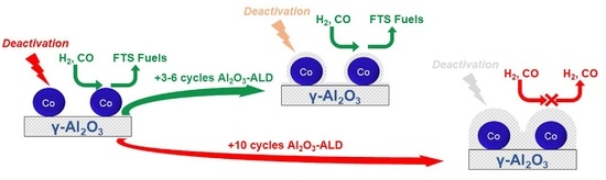
Passivation of Co/Al2O3 Catalyst by Atomic Layer Deposition to Reduce Deactivation in the Fischer–Tropsch Synthesis

1
Catalonia Institute for Energy Research (IREC), Jardins de les Dones de Negre 1, 08930 Sant Adrià de Besòs, Spain
2
Department of Mechanical, Chemical and Industrial Design Engineering, Universidad Politécnica de Madrid (UPM), ETSIDI, Ronda de Valencia 3, 28012 Madrid, Spain
3
Johnson Matthey, Belasis Avenue, Stockton-on-Tees, Billingham TS23 1LH, UK
4
Department of Materials Science and Physical Chemistry, Universitat de Barcelona (UB), Martí i Franquès 1, 08028 Barcelona, Spain
*
Author to whom correspondence should be addressed.
Catalysts 2021, 11(6), 732; https://doi.org/10.3390/catal11060732
Submission received: 26 May 2021 / Revised: 8 June 2021 / Accepted: 10 June 2021 / Published: 14 June 2021

Abstract

:
The present work explores the technical feasibility of passivating a Co/γ-Al2O3 catalyst by atomic layer deposition (ALD) to reduce deactivation rate during Fischer–Tropsch synthesis (FTS). Three samples of the reference catalyst were passivated using different numbers of ALD cycles (3, 6 and 10). Characterization results revealed that a shell of the passivating agent (Al2O3) grew around catalyst particles. This shell did not affect the properties of passivated samples below 10 cycles, in which catalyst reduction was hindered. Catalytic tests at 50% CO conversion evidenced that 3 and 6 ALD cycles increased catalyst stability without significantly affecting the catalytic performance, whereas 10 cycles caused blockage of the active phase that led to a strong decrease of catalytic activity. Catalyst deactivation modelling and tests at 60% CO conversion served to conclude that 3 to 6 ALD cycles reduced Co/γ-Al2O3 deactivation, so that the technical feasibility of this technique was proven in FTS.

Graphical Abstract

1. Introduction

Nowadays, Fischer–Tropsch synthesis (FTS) has regained interest motivated by the development of two concepts. On the one hand, the biorefinery concept, which is focused on producing chemicals and fuels from biomass sources; on the other hand, carbon capture and utilization (CCU), which is focused on producing these compounds from CO2 as feedstock [1]. The aim of FTS is to convert syngas, which is produced from biomass gasification or from the reverse water–gas shift reaction, into hydrocarbons through heterogeneous catalysts, usually based on Fe or Co. Fe-based catalysts are more suitable when light hydrocarbons and alcohols are desired, whereas Co-based ones are more selective for middle distillates and waxes.
Despite being discovered more than a century ago, FTS is still facing some economic and technical challenges, which hinder its consolidation as a viable alternative to producing synthetic fuels from renewable sources. In this regard, catalyst deactivation is a major technical issue. According to literature, the main causes of cobalt catalyst deactivation could be: poisoning due to the presence of S, N and alkali metals, reoxidation of cobalt species, coke deposition, sintering of cobalt crystallites, metal-support solid state reactions and particle attrition. Some of these phenomena, such as poisoning by sulfur compounds, can be minimized by the incorporation of sulfur-trap units based on metal–oxide adsorption columns before the reactor [2].
However, literature review shows the complexity of the Fischer–Tropsch reaction system. Sintering, carbon formation, fouling, metal reoxidation and even leaching and attrition can be involved [3]. In particular, there is still discussion about the true impact of coke deposition on catalyst deactivation [4,5]. Initial activity decay can also be attributed to the increasing mass transfer limitations resulting from wax and oil deposition [6]. Nonetheless, sintering [7] and reoxidation of cobalt species [8] are most likely the major causes of catalyst deactivation. It is reported that both phenomena occurred because of the water vapor coproduced during FTS [9,10].
Stabilization of the active phase particles, either by encapsulation or immobilization, has been reported as a way to reduce catalyst deactivation. In this sense, Yang et al. [11] synthesized silica-encapsulated core-shell Co/SiO2 with different thickness of the SiO2 shell layer. They came to the conclusion that a small layer thickness of SiO2 allowed the water vapor diffusion out of the catalyst surface and the pore channels to alleviate catalyst deactivation. Phaahlamohlaka et al. [12] developed a sinter-resistant RuCo/TiO2 catalyst through coating with a mesoporous silica shell. As a result, they synthesized a catalyst that was less prone to Co metal growth than the corresponding uncoated one. The results reported in these works suggest that alternative stabilization methods, such as atomic layer deposition (ALD), may also give positive results in terms of preventing FTS cobalt catalyst from deactivation.
ALD is a thin-film deposition technique based on sequential, self-limiting surface reactions between vapor-phase precursors and a solid substrate surface. Compared with other deposition techniques such as chemical vapor deposition (CVD), the self-limiting growth mechanism of ALD enables excellent film conformality, accurate thickness control, tunable film composition and penetration into a wide variety of surfaces [13]. ALD has been applied in various industrial and research applications such as microelectronics, photovoltaics and energy storage. Regarding heterogeneous catalysis, ALD attracted the attention of those researchers who desired to synthesize catalysts with an exhaustive control over the particle size, composition and morphology. Besides, the feasibility of ALD overcoating as a catalyst passivation technique has also been demonstrated on several reactions. By ALD overcoating, it is possible to provide stability to the catalyst against sintering in those applications where this deactivation phenomenon is relevant [14,15,16].
Baktash et al. [17] overcoated nickel nanoparticles by Al2O3-ALD technique for dry reforming of methane. They studied the effect of the number of Al2O3 cycles applied to the NiO nanoparticles on the performance and stability of the resulting catalyst. Results revealed that the material prepared with 5 cycles of Al2O3 ALD was more active and resistant to sintering, especially at elevated temperatures (700–800 °C). Feng et al. [18] applied Al2O3 overcoating over a Pd/SiO2 catalyst and they tested it in the methanol decomposition reaction. Those catalysts coated with less than 16 cycles of Al2O3-ALD were more resistant to sintering and, in some cases, even more active than the reference sample. Lee et al. [19] improved the stability of cobalt catalysts for aqueous-phase reactions using TiO2-ALD. In this case ALD again showed positive effects against sintering [20].
Concerning FTS, most works are focused on the direct incorporation of the active phase by this technique, rather than passivation. For instance, Najafabadi et al. [21] synthesized Co/γ-Al2O3 catalysts by depositing a cobalt precursor—cobalt (II) acetylacetonate—on the support by ALD. The main purpose of the authors was to have better control of cobalt oxide nanoparticle distribution, which led to catalysts with higher activity and selectivity. The authors conclude that the catalyst prepared by this technique, specifically with 6 ALD cycles, showed 38% higher conversion, 30% higher C5+ selectivity and 28% less CH4 selectivity than a reference one prepared by the impregnation method. With the aim of using ALD for passivation, to the best of our knowledge, there is only one preliminary work reported by Eskelinen et al. [22], in which the effect of ALD passivation on a 30/0.1 wt.% Co/Pt catalyst supported on γ-Al2O3 was studied, using Al2O3 as passivation agent. The main conclusion was that ALD depositions reduced the average crystallite size, as they prevented catalyst sintering. Five ALD cycles increased activity and methanation selectivity, whereas at 20 cycles the properties were similar to those of the unmodified catalyst. The authors recommended further work in order to have a broader view of this potential catalyst passivation technique.
The aim of this work is to study the effect of ALD Al2O3 overcoating as a passivation technique on the morphology and the catalytic performance of Co/Al2O3 catalysts in FTS. In the present case, a Co/γ-Al2O3 microcatalyst was used as a reference in order to propose a more stable catalyst for its potential application in the incipient microreactor technology. The relationship between long-term catalytic activity and catalyst properties is discussed.

2. Results and Discussion

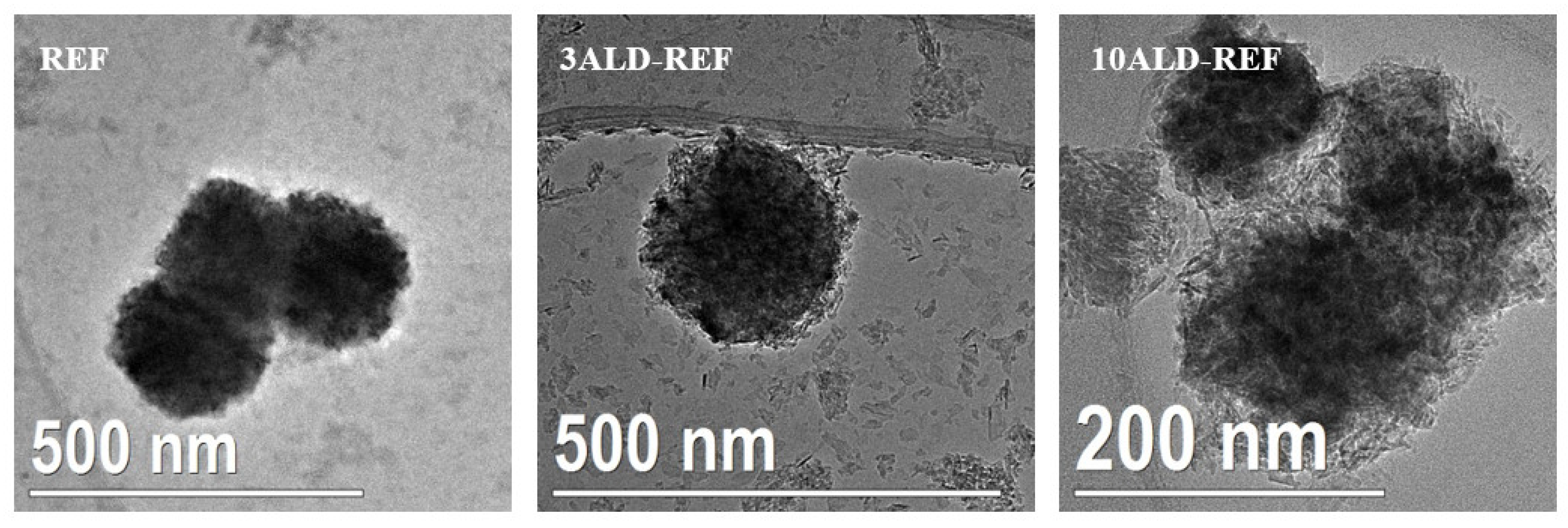
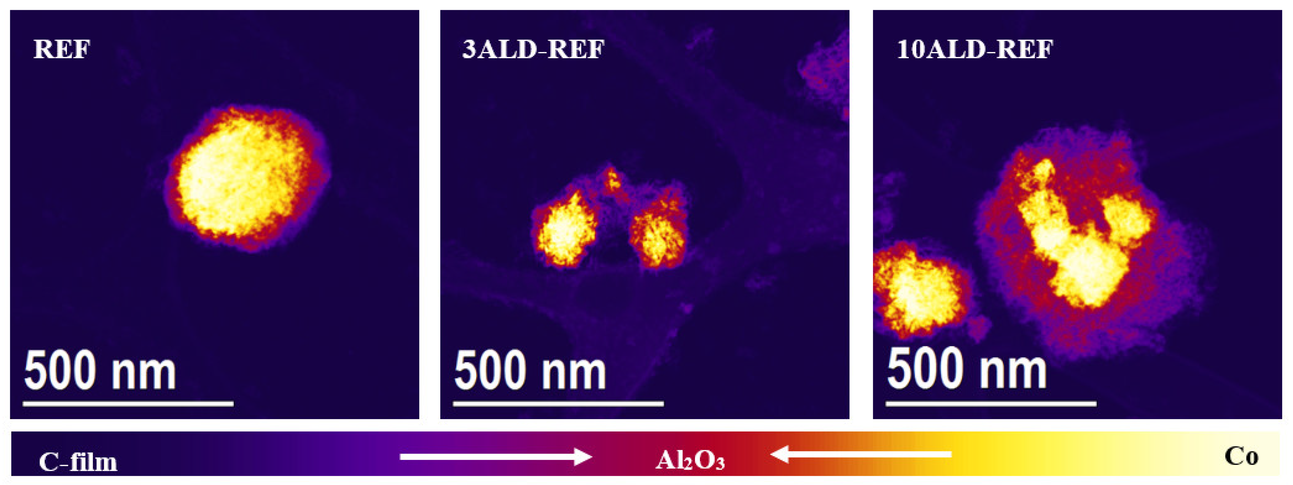
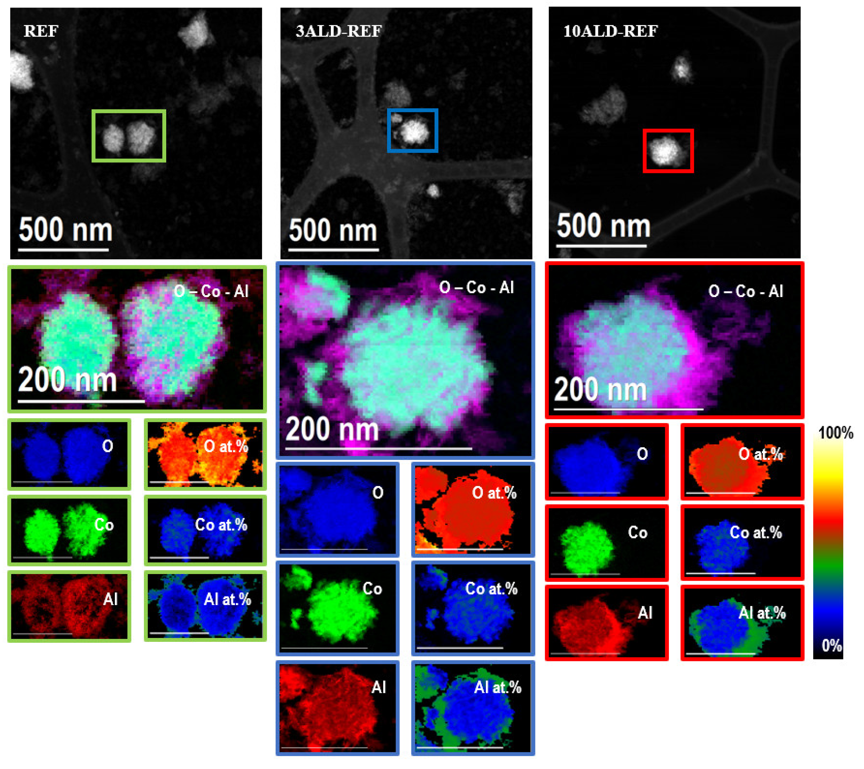
2.1. Catalyst Characterization

Table 1 lists the main characterization results obtained in the overcoated catalyst samples. At first sight, it is observed that the incorporation of Al2O3 on the catalyst by ALD cycles did not lead to significant morphology changes, neither in textural properties nor in the Co crystallite size. However, important differences in the reduction behavior of cobalt particles were inferred.
Figure 1 shows the nitrogen adsorption-desorption isotherms and the mesopore distribution of the support—γ-Al2O3—and the catalysts evaluated in the present work. All samples showed a type IV isotherm, according to IUPAC classification, which is typical of mesoporous materials, without noticeable nitrogen adsorption in the micropore range (P/P0 ≤ 0.03) and a significant increase in the mesopore range. The hysteresis loop observed in all samples (Type H4, according to IUPAC classification) [23] indicated the presence of slit-type pore and was due to capillary condensation in the mesopores. Results evidenced that porosity was induced by the support, rather than by cobalt nanoparticles.
On the one hand, it is observed that nitrogen adsorption of the cobalt catalysts (161–163 m2/g) was significantly lower than that of the support (216 m2/g), which evidenced that cobalt particles partially blocked the pores of the support during impregnation procedure, as reported elsewhere [24]. This pore blockage is confirmed by BJH desorption results, also revealing that cobalt particles were deposited uniformly on the support mesopores. On the other hand, there were no differences between BET surface area and pore volume of samples REF and ALD-coated ones, which revealed that atomic layer deposition did not lead to noticeable changes in the porosity of the catalyst.
XRD diffractograms of all samples are depicted in Figure 2. All catalysts showed a main narrow diffraction reflection, identified as the crystalline phase Co3O4, at 36.84° (ICDD Card No. 00-042-1467). Small reflections of this crystalline phase, at ca. 31.32°, 45.08°, 59.58° and 65.44°, were also detected. No more reflections were observed except some broad ones which were coincident to those of the Al2O3 support. Diffractograms of all catalysts were practically identical to each other, which revealed that ALD deposition carried out at 300 °C did not affect cobalt–alumina interactions. Indeed, cobalt crystallite size of all catalysts was similar (Table 1), taking into account the uncertainty associated with this calculation.
TPR profiles are depicted in Figure 3. In general, two main peaks were observed in all samples. The first hydrogen consumption (268–283 °C) was due to the reduction of Co3O4 to CoO, followed by the reduction of CoO to Co0 (481–530 °C) [25]. It is worth noting that sample REF showed a small shoulder at 202 °C, due to the presence of NOx from residual nitrates on this catalyst [26]. As ALD procedure is carried out, residual nitrates on ALD-passivated catalysts vanished during heating. Finally, samples 6ALD-REF and 10ALD-REF presented a small shoulder (620–642 °C) which can be linked to the formation of cobalt aluminate species.
Among samples, it is observed that 3ALD-REF did not show important differences in respect to REF (indeed, the peaks showed a slight shift to lower temperatures), whereas the peaks of samples 6ALD-REF and 10ALD-REF shifted to higher temperatures, especially the peak associated with the final reduction (CoO to Co0). Temperature shift to higher values indicates that cobalt species in these samples were more difficult to be reduced, which was directly related to the number of ALD cycles applied on them. In this way, it can be concluded that the higher the number of cycles, the harder the sample is to be reduced.
Two conclusions can be drawn from TPR profile analysis. On the one hand, overcoating by ALD may affect the diffusion of gas species (in this case H2) up to cobalt particles, leading to lower reduction degree at a certain overcoating level (10ALD-REF). On the other hand, during reduction the Al2O3 introduced by ALD may interact with cobalt particles to form irreducible species (cobalt aluminates) that are hard to reduce, as reported elsewhere [20]. In order to obtain the FT cobalt active phase (Co0) and avoid the formation of these irreducible cobalt aluminates, 380 °C was selected as the maximum reduction temperature. At this temperature, CoO reduction rate (i.e., the slope of the TPR curve) of samples REF, 3ALD-REF and 6ALD-REF was higher than that of 10ALD-REF, which was closely related to O2 titration results (see hereafter). As cobalt reduction rate was relatively low at this temperature, catalyst reduction procedure should last several hours. Therefore, 380 °C and 16 h were selected as reduction conditions prior to catalytic tests. Detailed reduction conditions are described in the experimental section.
The effect of ALD cycles on reduction properties was partially corroborated through the evaluation of the extent of cobalt reduction (Table 1). On one hand, similar extent of reduction (56.5–65.4%) was observed in samples REF, 3ALD-REF and 6ALD-REF (considering the accuracy of this technique). Although the TPR profiles of these samples were different from each other, it is possible to conclude that H2 diffusion up to cobalt particles was not hindered up to, at least, 6 ALD cycles. On the other hand, the extent of reduction attained in 10ALD-REF dropped sharply up to 11.1%.
Figure 4 shows low magnification TEM micrographs of samples REF, 3ALD-REF and 10ALD-REF, evidencing the general morphology of the catalyst samples. In order to have a clear view of the effect of ALD passivation, those images with exceptionally bigger Co agglomerates have been selected. As noticed, an Al2O3 shell grew surrounding the Co polycrystalline nanostructures in ALD-coated samples. Therefore, the passivation of samples led to an Al2O3 shell nanoflake-like morphology.
Analogously, high-angle annular dark-field scanning TEM images (STEM-HAADF, Figure 5) highlighted the presence of Al2O3 shell on ALD-coated samples. Images were reported in violet color palette in order to differentiate the species observed from the image contrast and therefore local color. Heavier atoms, in this case Co3O4, appear brighter than lighter compound, Al2O3. From this visual contrast it is possible to quantitatively recognize that the Al2O3 shell in sample 10ALD-REF fully covered the Co core. As expected, the higher the number of ALD cycles, the higher the shell thickness.
Finally, electron energy loss spectroscopy analysis in STEM mode (STEM-EELS) confirmed the presence of Al2O3 shell in ALD-passivated samples. The shell layer resulted in not being uniform. In this sense, values of ca. 3–7 nm were obtained in sample 3ALD-REF, whereas values of ca. 10–30 nm were obtained in sample 10ALD-REF. Results are reported in Figure 6, where elemental mapping evidences the local distribution of the different atomic species. In the same figure, relative composition analysis to evaluate Al, Co and O relative composition was also reported. For the elemental analysis, O K-edge at 532 eV (blue), Co L-edge at 779 eV (green) and Al K-edge at 1560 eV (red) were used. Although REF presented some Al2O3, the content was much lower than that presented by ALD-passivated samples, and can be linked to the presence of Al2O3 support traces. In any case, both the amount of Al2O3 and the layout around the cobalt particles, evidenced by the relative percentage of this species, revealed, on the one hand, how cobalt particles of ALD-passivated samples were covered by an Al2O3 shell, as well as how the number of ALD cycles affected the thickness of this shell.
Usually, the differences in reduction behavior of Co/Al2O3 catalysts are closely related to important changes in textural properties and/or cobalt particle size [27]. However, nitrogen physisorption and XRD results showed no difference among the samples used in this work, so that it is possible to conclude that ALD passivation only affected the reduction properties of these catalysts by the presence of a thin coating layer of ALD on the top of cobalt nanoparticles, while the rest of the properties were kept unchanged.

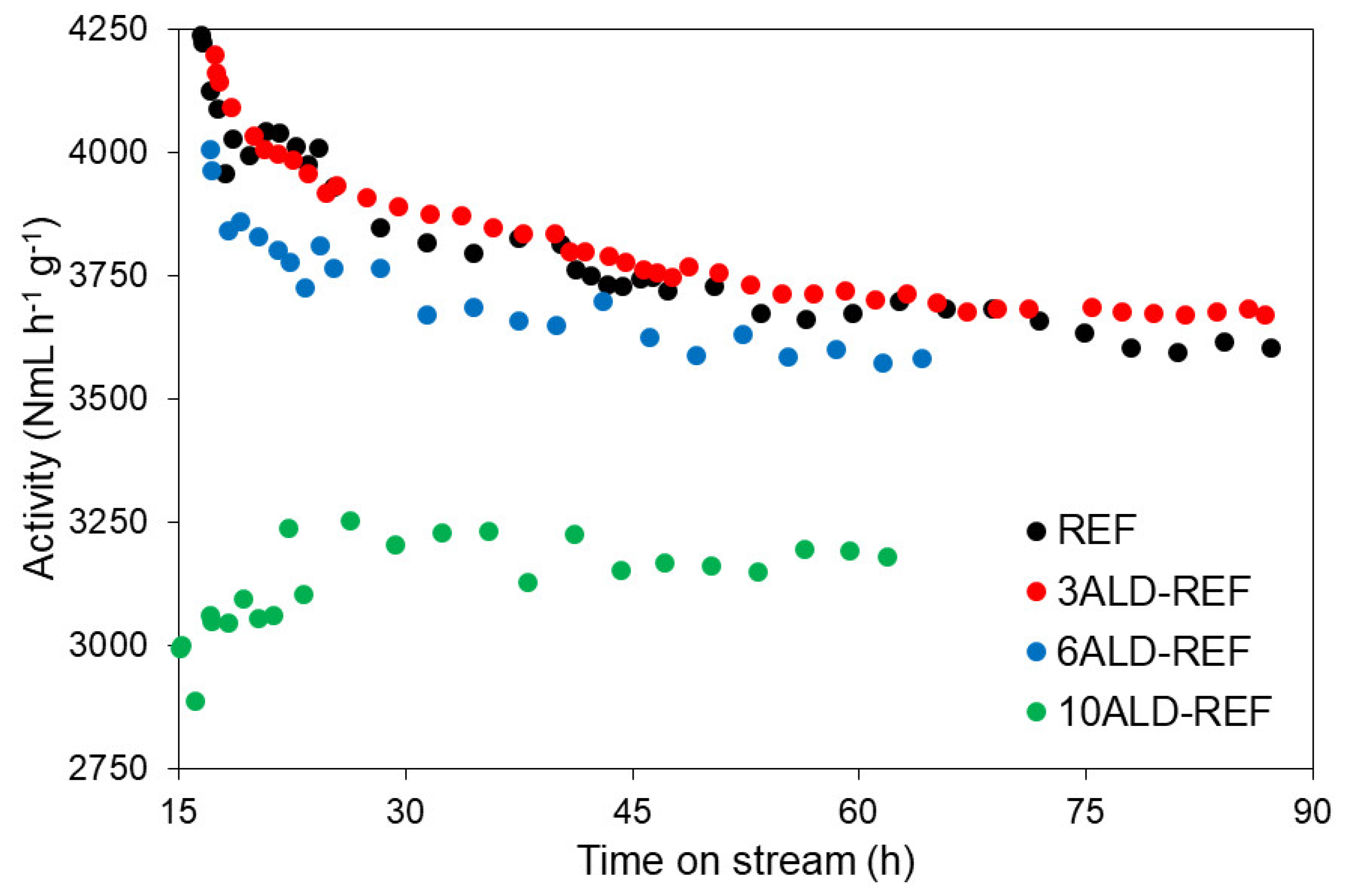
2.2. Catalytic Tests

2.2.1. Catalytic Performance at Regular Conditions (XCO ≈ 50%)

During each catalytic run, the following gas products were observed: CH4, CO2, C2H6, C2H4, C3H6, C3H8, C4H10 and traces of C5H12. Besides, liquid and solid products were obtained, which corresponded to hydrocarbons of longer chains (C5+). The maximum relative error observed between experimental species concentrations at equivalent time-on-stream (TOS) was less than 2%. Table 2 compares the activity results of all samples at two different times: 15–17 h (the time at which, once GHSV was adjusted, steady state was attained) and 87 h (otherwise the end of the experiment). In this work, activity was quantified as a function of GHSV and syngas conversion (Section 3, Equations (9) and (10)).
First of all, it is observed that, in all cases except 10ALD-REF, CO conversion experienced a significant decrease between the beginning (40.1–43.5%) and the end (34.8–36.7%) of the reaction, which confirmed catalytic activity loss in the respective catalysts. In contrast, sample 10ALD-REF showed initially lower CO conversion than REF (28.1 vs. 43.5%), and then experienced a slight increase up to 30.2%.
As for selectivity, all samples showed, on the one hand, important CH4 selectivity values, being caused by undesired CO methanation reaction. In particular, high CH4 selectivity (32.1%) was observed in sample 10ALD-REF, which consequently led to low selectivity to C5+ (57.2%). As reaction went by, CH4 selectivity values decreased in all cases, this decrease being sharp in sample 10ALD-REF. This CH4 selectivity decrease observed in sample 10ALD-REF, together with the increase in CO conversion, suggested that the active phase of this catalyst experienced changes during the time on stream, as explained hereafter. On the other hand, CO2 selectivity, caused by reverse water gas shift reaction (RWGS), whose value was lower than 1%. C2–C4 selectivity values, which shed light about catalyst chain growth, revealed that generally speaking, all samples showed similar values.
Concerning activity values, results revealed that the number of ALD cycles affected the FTS catalytic performance. Initially, the relative activity of all ALD-coated samples was lower than that of REF, although the initial values of 3ALD-REF (0.99) and 6ALD-REF (0.95) were practically similar. At the other end, initial relative activity of 10ALD-REF was around 30% lower than that of REF. At the end of the experiment, interesting results were observed. Firstly, activity of sample 3ALD-REF was higher than that of the REF, as the relative activity value rose up to 1.02. Then, initial activity loss of 6ALD-REF was partially recovered, so that relative activity of 6ALD-REF rose from 0.95 to 0.97.
As for the selectivity, if results are evaluated in terms of yield to liquid and wax products (YC5+), it is observed that, at the beginning of the reaction, the values of ALD-passivated samples were lower than those of the reference, but then they reached practically the same value (6ALD-REF) or even higher (3ALD-REF), so that it is possible to conclude that ALD overcoating also favored the catalytic selectivity to the desired products.
In order to have a more detailed view about catalyst activity, Figure 7 depicts the evolution of activity of all catalysts studied, which sheds light about their behavior with time on stream (TOS). On the one hand, samples REF, 3ALD-REF and 6ALD-REF exhibited similar activity profiles, showing an initial sharp activity drop, followed by a more gradual decline in activity. On the other hand, activity of sample 10ALD-REF increased at the beginning of the reaction, followed by stabilization at ca. 30 h of TOS. Taking into account TPR and O2 titration results, it is possible to conclude that, at the beginning, cobalt particles of 10ALD-REF were reduced by part of the syngas fed into the reactor, which consequently led to an increase of the catalytic activity. Activation of cobalt catalysts in syngas atmosphere has been reported elsewhere [28]. The high stability observed in this catalyst after 30 h of TOS suggests that, in general, ALD passivation conferred stability to the catalyst in all cases. Moreover, it is observed that, the higher the number of ALD cycles, the more stable the catalyst was.
Regarding sample 3ALD-REF, although initial activity value was slightly lower than that of REF, then this value started to be higher after ca. 25 h TOS. The gap between the activity of this catalyst and REF was getting broader and broader, until maximum gap seemed to be attained at the end of the experiment. Finally, sample 6ALD-REF also showed interesting results. Although the initial relative activity of this catalyst was slightly lower than that of REF, the gap between activities seemed to narrow as reaction advanced. This fact was corroborated by the activity ratio, as quantified above (see Table 2).
As the aim of ALD passivation is to confer stability to the catalyst without affecting activity, results of 3ALD-REF and 6ALD-REF showed that these were the most promising samples. After practically 90 h of experiment, 3ALD-REF exhibited slightly higher activity than the reference, which proves that this technique can be used to increase the resistance of Co/Al2O3 to deactivation. In order to compare quantitatively the deactivation rate of samples REF, 3ALD-REF and 6ALD-REF, deactivation modelling was carried out using a generalized power-Llw expression (GPLE) proposed by Bartholomew [29,30]:
d a d t = k d · f ( P i ) · a d
where a stands for the relationship between the reaction rate at any time and the initial value ( W c a t refers to catalyst mass):
a ( t ) = r C O ( t ) r C O ( 0 ) = ( F C O ( t ) F C O , 0 ) / W c a t ( F C O ( 0 ) F C O , 0 ) / W c a t
k d is the deactivation rate constant. f ( P i ) stands for a power-law expression of the deactivation rate dependence on the concentration (partial pressure) of reactants, products and/or poisons. Previously, it was stated f ( P i ) = P H 2 O P C O + P H 2 F H 2 O F C O + F H 2 as a criterion for estimating the deactivation rate of cobalt catalysts in FTS [31]. F H 2 O was calculated based on the oxygen balance between the reactor feed and the reactor outlet. Moreover, it is assumed that activity did not decline up to any steady state, since this value could not be obtained accurately. The exponent d is the order of deactivation, so that the following expressions can be obtained:
0 th   order :   a ( t ) = k d · f ( P i ) · t + 1
1 st   order :   a ( t ) = exp ( k d · f ( P i ) · t ) .   Linear   fitting :   ln ( ( a ( t ) ) = k d · f ( P i ) · t
2 nd   order :   a ( t ) = 1 / ( k d · f ( P i ) · t + 1 ) .   Linear   fitting :   1 / a = k d · f ( P i ) · t + 1
Table 3 lists the linear fitting results for the three orders of deactivation above described.
Modelling of the experimental results suggested that catalyst deactivation can be fitted to a 1st or 2nd order of GPLE, although the accuracy of the fitting was not enough to draw a clear conclusion about this point. What is more important is the fact that, whether deactivation obeys a 0th, 1st or 2nd order, deactivation rate constants ( k d ) of ALD-passivated samples were lower than those of REF sample and the deactivation rate constant was directly related to the number of ALD cycles applied. Lower k d means less deactivation rate, so that the benefit of ALD passivation on reducing catalyst deactivation in FTS was confirmed.

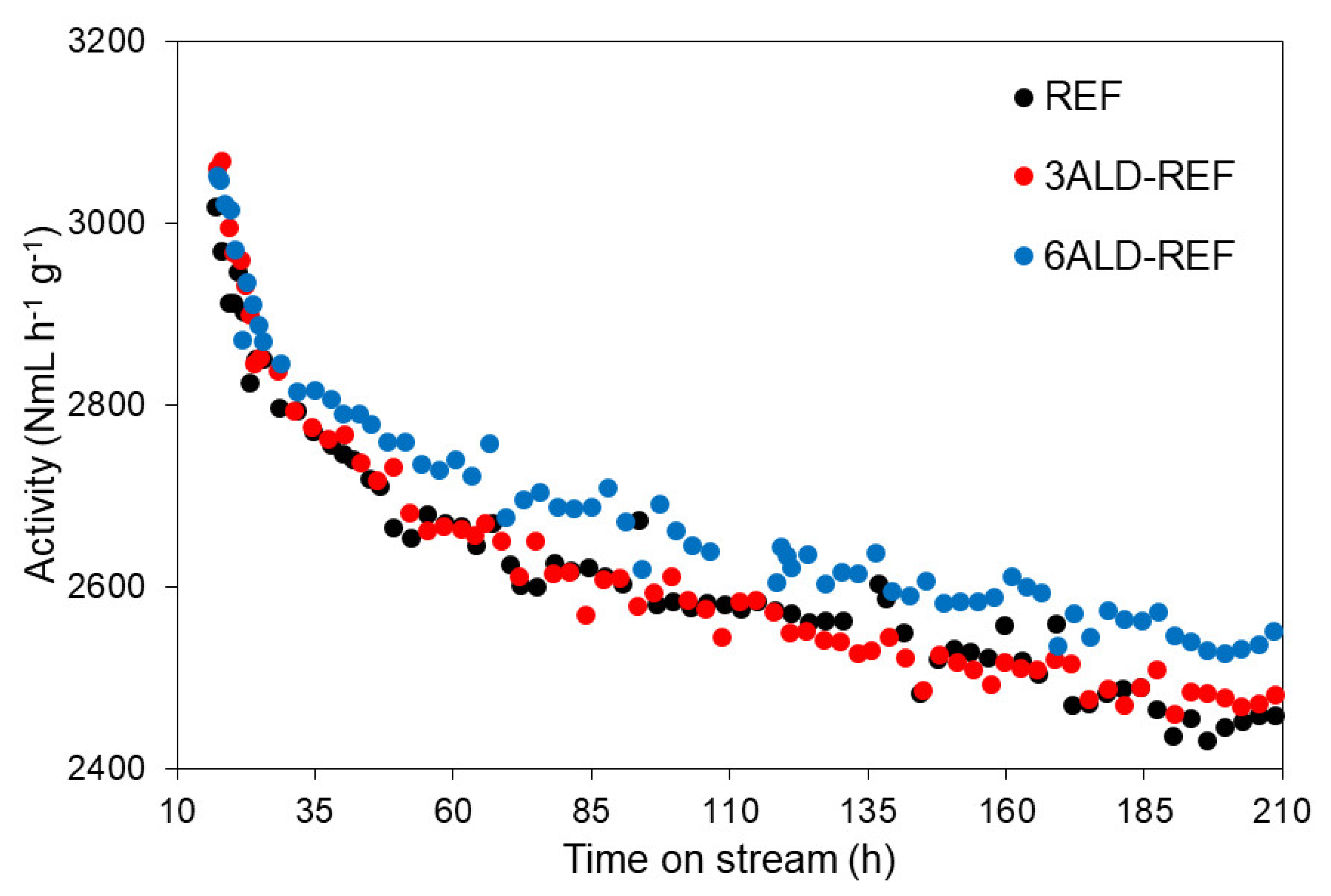
2.2.2. Catalytic Performance at Accelerated Deactivation Conditions (XCO ≈ 60%)

Although GPLE fitting and k d estimation give a first estimation of how ALD-coated samples would behave with respect to REF catalyst, further experiments at accelerated deactivation conditions were carried out in order to have a complementary experimental view of this behavior. Samples REF, 3ALD-REF and 6ALD-REF were submitted to tests at higher CO conversion level (≈60%) with the aim of evaluating their behavior in this so-called environment of accelerated deactivation. The higher the CO conversion, the higher the H2O concentration, one of the most important deactivation agents in FTS [3,26]. Results are listed in Table 4. In addition, 10ALD-REF was not evaluated at these harder conditions due to the lower catalytic activity previously observed.
Interesting facts can be remarked from results shown in this table. On the one hand, it should be noted that, using these conditions, the relative activity of sample 6ALD-REF was becoming higher and higher, whereas that of 3ALD-REF remained constant, although slightly higher than 1, i.e., higher than the activity of sample REF. On the other hand, the yield of ALD-passivated samples was lower than that of the reference in the starting point, although then these values started to increase.
Although these results seemed to give a different optimum value, it should be noted that reaction conditions in these tests were different from those performed at regular conditions. Indeed, the strong decrease of GHSV required in experiments at accelerated deactivation conditions suggested a possible change in the rate controlling step, then confirmed by experimental procedure (results not shown). In any case, FTS tests altogether confirmed that a small number of ALD cycles conferred stability to the catalyst. Figure 8 depicts the variation of the activity of studied samples versus TOS. Again, profiles of samples REF, 3ALD-REF and 6ALD-REF were similar to each other, although the activity of sample 6ALD-REF started to become higher than that of the other samples from 35 h TOS. Moreover, the gap between 6ALD-REF and the other samples was becoming higher and higher as the reaction progressed. Finally, the activity of 3ALD-REF was slightly higher than that of REF; however, the difference was lower than the margin of error, so no specific conclusion can be drawn.

3. Materials and Methods

3.1. ALD Passivation Procedure

A microcatalyst (Co/γ-Al2O3, 16.3 wt.% cobalt) was used as a reference. This catalyst was synthesized by incipient wetness impregnation of the cobalt precursor onto spheres of γ-Al2O3 (500 µm), following the procedure described in [26].
The ALD passivation procedure was carried out directly in the catalyst (3 g) in an R200 Picosun atomic layer deposition equipped with a POCA 200 powder coating system. Trimethylaluminum (TMA, Sigma Aldrich, Germany), 663301-25G, electronic grade) and H2O precursors were introduced and purged with N2 (99.999%, Linde, Spain) in successive cycles, following the sequence TMA-N2-H2O-N2. The time sequence of each cycle was 1.5-60–1.5-60 (s). The process was performed at 300 °C. Table 5 lists the samples prepared for the present study.

3.2. Sample Characterization

Textural properties were determined from N2-physisorption (adsorption/desorption) isotherms recorded by a TriStar II 3020-Micromeritics sorption analyzer. Prior to the measurements, the samples were degassed at 90 °C for 1 h, and then at 250 °C for 4 h on a FlowPrep 060 (Micromeritics, Norcross, GA, USA). Brunauer–Emmett–Teller (BET) method was used to calculate the BET surface area for a relative pressure (P·P0−1) range between 0.05 and 0.30. Furthermore, Barrett–Joyner–Halenda (BJH) method applied to desorption branch of the isotherm was used to determine the mesopore volume.
Structural properties were studied by powder X-ray diffraction (XRD). The wide-angles data were obtained on a XRD D8 Advance A25 diffractometer (Bruker, Billerica, MA, USA) using Cu Kα radiation (λ = 1.5406 mm), a voltage of 40 kV, a current of 40 mA and a step size of 0.05° (with 3 s duration at each step). The acquisitions were done in a range from 20° to 80°. The software X’Pert HighScorePlus was used to identify the crystalline phase using the standard powder XRD files published by the International Centre for Diffraction Data (ICDD). The average crystal size was calculated using the Scherer’s equation: dCo3O4 = (Kλ/βCosƟ), where λ is the X-ray wavelength, β is the full width of the diffraction line at half maximum (FWHM) and Ɵ is the Bragg angle.
Reducibility of the catalysts was analyzed by temperature programmed reduction method (H2-TPR) on an Autochem (Micromeritics, Norcross, GA, USA). In each run, 150 mg of fresh calcined catalyst was used for the analysis. The H2-TPR measurements were conducted using 12 vol.% H2/Ar at a flow of 50 NmL·min−1 in the temperature range of 35 to 800 °C and a heating ramp of 10 °C·min−1. The extent of cobalt reduction was studied using O2 titration experiments, which were conducted in the same apparatus as was used for the TPR experiments. Firstly, samples were reduced once H2-TPR results have been discussed (see below). After reduction, sample was kept at 380 °C in He and held for 1 h to desorb any chemisorbed H2. Calibrated pulses of O2 were then added into the continuous He flow until further consumption of O2 was not detected by the TCD located downstream from the reactor. The extent of reduction was calculated assuming stoichiometric reoxidation of Co0 to Co3O4.
The morphology of the catalyst was visually analyzed by high-resolution transmission electron microscopy (HRTEM) together with scanning TEM (STEM). Investigation was performed on a field emission gun FEI Tecnai F20 microscope (Thermo Fischer Scientific, Waltham, MA, USA). High angle annular dark-field (HAADF) STEM was combined with electron energy loss spectroscopy (EELS) in the Tecnai microscope by using a GATAN QUANTUM filter (Thermo Fischer Scientific, Waltham, MA, USA). For TEM analyses, sample particles were crushed, seeing the large particle size, and the obtained powder was dispersed in pure ethanol. Then, a few drops of the above suspension were deposited on a C-coated TEM Cu grid.

3.3. Catalytic Tests

Fischer–Tropsch catalytic studies were carried out in a laboratory scale fixed-bed reactor (Microactivity Reference, PID Eng&Tech, Spain). In each run, samples (0.5 g) were diluted in 5 g of SiC 46 grit (Sigma-Aldrich) to minimize the temperature gradients throughout the catalytic bed. Hydrogen (99.999%, Linde), carbon monoxide (99.5%, Linde) and nitrogen (99.999%, Linde) were used in each catalytic run. Firstly, samples were reduced in 100 NmL/min of hydrogen at 380 °C and atmospheric pressure, with a hold time of 7 h and a heating ramp of 1 °C/min. Then, the system was cooled to 150 °C under hydrogen atmosphere. Once this temperature was attained, 200 NmL/min of the reactant mixture was introduced (H2/CO ≈ 2 (v/v) and 5% N2 (v/v) as internal standard) and pressure was raised to 20 barg. This step was kept for 6 h, during which the concentration of the reactant mixture was analyzed and taken as a reference for calculations (blank experiment). Afterwards, temperature had risen to 230 °C to begin the reaction, keeping 200 NmL/min of reactant flow during 16 h. Finally, the GHSV was adjusted to a specific value depending on the set of the experiments. In a first set of experiments, referred to as “regular conditions”, GHSV was adjusted to 8400 NmL/g∙h to obtain an intermediate level of conversion. At this GHSV, CO conversion reached approximately 50% over REF. A second set of experiments, referred to as “accelerated deactivation conditions” was also performed, in which 1 g catalyst was diluted in 5 g of SiC 46 grit, and GHSV was adjusted to 4800 NmL/g∙h to attain, approximately, 60% CO conversion over REF.
After reaction, the reactor effluent passed through two consecutive traps. In the first one (100 °C and 20 barg), waxes were trapped together with some H2O, whereas the second one (10 °C and 20 barg) retained the liquid hydrocarbons and remaining H2O. The whole system (traps excluded) was placed in a hot box at 150 °C to avoid possible condensations on the tubing. The gas effluent (light hydrocarbons, CO2 and the remaining reactant mixture) was analyzed online with a gas microchromatograph equipped with a TCD (490 microGC, Agilent Technologies, Madrid, Spain), which was previously calibrated using different cylinders and N2 as standard.

3.4. Evaluation of Catalytic Performance

CO, H2 and syngas conversion (Xi) were calculated using the following formula:
X i ( % ) = 100 · F i , 0 F i F i , 0
where F is the molar flow and i refers to CO, H2 or the sum of both species. Fi was evaluated using the concentration of the N2 as internal standard in the effluent stream. Selectivity (Si) to gas products (CO2 and light hydrocarbons) with respect to CO was calculated as follows:
S i ( % ) = 100 · δ i · F i F C O , 0 F C O
where δ refers to the stoichiometric factor of CO with respect to that of the product i (CH4, CO2, C2H6, C2H4, C3H8, C3H6, C4H10). Selectivity to liquid and wax products (SC5+) was obtained considering a carbon balance of 100%:
S C 5 + = 100   S i
The activity of the catalyst was quantified as a function of the GHSV and the syngas conversion, according to the following equation:
A = G H S V ( N m L · g 1 · h 1 ) · X S y n g a s 100
being syngas conversion calculated as follows:
X S y n g a s =   F i , i n   F i , o u t   F i , i n
where F i , i n the molar inlet flow and F i , o u t the molar outlet flow. i refers to H2 and CO.
Besides, the yield to liquid and wax products (YC5+) was calculated using the formula:
Y C 5 + = X C O ( % ) · S C 5 + ( % ) 100
To compare the ALD-passivated samples, relative activity values were evaluated at any time with respect to those of the reference catalyst (Aref and YC5+ref).

4. Conclusions

The results obtained in this work gave two main conclusions. Firstly, it was proven that ALD passivation is a promising technique to increase the resistance of Co-based catalysts against deactivation in FTS. Secondly, the differences between ALD-coated samples in such a narrow range (3–10 coatings) make it necessary to carry out exhaustive control of the number of passivation cycles, which is one of the main features of this technique.
Characterization results revealed that ALD did not affect either textural properties or cobalt crystallite size. The main differences were observed in TPR and O2 titration experiments, as the number of ALD cycles affected catalyst reduction properties. In this sense, 61.4, 56.5 and 65.4% of Co contained in samples REF, 3ALD-REF and 6ALD-REF was respectively reduced, whereas only 11.1% of that in sample 10ALD-REF did. As for TEM results, it was clearly observed that a shell of Al2O3 (ALD passivating agent) was formed around cobalt particles, and the thickness of this shell was closely related to the number of ALD cycles applied on the catalyst.
Catalytic tests at regular conditions (XCO ≈ 50%) confirmed that sample 10ALD-REF resulted in being overcoated, so that in the first stages of the experiment, syngas role was reducing Co particles that resulted in not being reduced in the previous reduction step. Consequently, an initial relatively low CO conversion was observed, which started to increase slightly as reaction went by. Conversely, samples 3ALD-REF and 6ALD-REF showed promising results, as they reflected the double objective of ALD passivation, that is, conferring stability without affecting catalytic activity. Besides, ALD-coated samples were more selective to hydrocarbons of longer chain. Fitting experimental results to a GPLE function corroborated that these samples were more resistant to deactivation than REF, as the k d values of ALD-passivated samples were lower than those of REF. In order to confirm this promising estimation, experiments at accelerated deactivation conditions (XCO ≈ 60%) were carried out, confirming that 6ALD-REF catalyst showed better results in terms of activity and stability, whereas 3ALD-REF performance overlapped that of sample REF.
Therefore, the results presented in this work confirmed ALD as a promising technique for cobalt catalyst to gain resistance against deactivation. Specifically, 3 to 6 ALD cycles would be sufficient to increase catalyst stability, whereas a higher number of cycles (10) led to blocking of cobalt particles, avoiding transport of reactants up to catalyst surface. Therefore, the technical feasibility of passivating a Co/γ-Al2O3 catalyst by atomic layer deposition (ALD) to reduce deactivation rate during FTS has been confirmed. However, the positive effect observed was very small and more effort should be addressed in order to further increase the stability of the reference catalyst. Further studies dealing in depth with the causes of catalyst deactivation and how ALD prevents them are recommended.

Author Contributions

Conceptualization, T.A. and J.G.; Methodology, J.A.D.-L. and M.B.-P.; Formal Analysis and Data Curation, T.A., J.G. and J.A.D.-L.; Resources, G.K. and D.E.; Writing—Original Draft Preparation, J.A.D.-L. and J.G.; Writing—Review & Editing, J.A.D.-L., J.G. and T.A.; Supervision, Project Administration and Funding Acquisition, T.A. All authors have read and agreed to the published version of the manuscript.

Funding

The project leading to this research has received funding from the European Union’s Horizon 2020 research and innovation program under grant agreement No 764675 (Heat-To-Fuel Project). IREC is funded by the CERCA Programme and Generalitat de Catalunya (2017SGR1246).

Acknowledgments

The authors gratefully acknowledge the contribution of Maria Chiara Spadaro and Jordi Arbiol, who carried out TEM, STEM-HAADF and STEM-EELS and also contributed to discussion of the results obtained by these characterization techniques. The authors also acknowledge the contribution of Joan Ramón Morante for the conceptualization and coordination of this work.

Conflicts of Interest

The authors declare no conflict of interest.

References

  1. Panzone, C.; Philippe, R.; Chappaz, A.; Fongarland, P.; Bengaouer, A. Power-to-Liquid catalytic CO2 valorization into fuels and chemicals: Focus on the Fischer-Tropsch route. J. CO2 Util. 2020, 38, 314–347. [Google Scholar] [CrossRef]
  2. Pishahang, M.; Larring, Y.; Van Dijk, E.; Van Berkel, F.; Dahl, P.I.; Cobden, P.; McCann, M.; Bakken, E. Regenerative Copper-Alumina H2S Sorbent for Hot Gas Cleaning through Chemical Swing Adsorption. Ind. Eng. Chem. Res. 2016, 55, 1024–1032. [Google Scholar] [CrossRef]
  3. Tsakoumis, N.E.; Rønning, M.; Borg, Ø.; Rytter, E.; Holmen, A. Deactivation of cobalt based Fischer-Tropsch catalysts: A review. Catal. Today 2010, 154, 162–182. [Google Scholar] [CrossRef]
  4. Moodley, D.J.; van de Loosdrecht, J.; Saib, A.M.; Overett, M.J.; Datye, A.K.; Niemantsverdriet, J.W. Carbon deposition as a deactivation mechanism of cobalt-based Fischer–Tropsch synthesis catalysts under realistic conditions. Appl. Catal. A Gen. 2009, 354, 102–110. [Google Scholar] [CrossRef]
  5. Chen, W.; Kimpel, T.F.; Song, Y.; Chiang, F.K.; Zijlstra, B.; Pestman, R.; Wang, P.; Hensen, E.J.M. Influence of Carbon Deposits on the Cobalt-Catalyzed Fischer-Tropsch Reaction: Evidence of a Two-Site Reaction Model. ACS Catal. 2018, 8, 1580–1590. [Google Scholar] [CrossRef]
  6. Vázquez, F.V.; Koponen, J.; Ruuskanen, V.; Bajamundi, C.; Kosonen, A.; Simell, P.; Ahola, J.; Frilund, C.; Elfving, J.; Reinikainen, M.; et al. Power-to-X technology using renewable electricity and carbon dioxide from ambient air: SOLETAIR proof-of-concept and improved process concept. J. CO2 Util. 2018, 28, 235–246. [Google Scholar] [CrossRef]
  7. Rahmati, M.; Safdari, M.-S.; Fletcher, T.H.; Argyle, M.D.; Bartholomew, C.H. Chemical and Thermal Sintering of Supported Metals with Emphasis on Cobalt Catalysts During Fischer–Tropsch Synthesis. Chem. Rev. 2020, 120, 4455–4533. [Google Scholar] [CrossRef]
  8. van de Loosdrecht, J.; Balzhinimaev, B.; Dalmon, J.-A.; Niemantsverdriet, J.W.; Tsybulya, S.V.; Saib, A.M.; van Berge, P.J.; Visagie, J.L. Cobalt Fischer-Tropsch synthesis: Deactivation by oxidation? Catal. Today 2007, 123, 293–302. [Google Scholar] [CrossRef]
  9. Wolf, M.; Fischer, N.; Claeys, M. Water-induced deactivation of cobalt-based Fischer–Tropsch catalysts. Nat. Catal. 2020, 3, 962–965. [Google Scholar] [CrossRef]
  10. Rytter, E.; Holmen, A. Deactivation and Regeneration of Commercial Type Fischer-Tropsch Co-Catalysts—A Mini-Review. Catalysts 2015, 5, 478–499. [Google Scholar] [CrossRef] [Green Version]
  11. Yang, J.; Fang, X.; Xu, Y.; Liu, X. Investigation of the deactivation behavior of Co catalysts in Fischer–Tropsch synthesis using encapsulated Co nanoparticles with controlled SiO2 shell layer thickness. Catal. Sci. Technol. 2020, 10, 1182–1192. [Google Scholar] [CrossRef]
  12. Phaahlamohlaka, T.N.; Dlamini, M.W.; Mogodi, M.W.; Kumi, D.O.; Jewell, L.L.; Billing, D.G.; Coville, N.J. A sinter resistant Co Fischer-Tropsch catalyst promoted with Ru and supported on titania encapsulated by mesoporous silica. Appl. Catal. A Gen. 2018, 552, 129–137. [Google Scholar] [CrossRef] [Green Version]
  13. Singh, J.A.; Yang, N.; Bent, S.F. Nanoengineering Heterogeneous Catalysts by Atomic Layer Deposition. Annu. Rev. Chem. Biomol. Eng. 2017, 8, 41–62. [Google Scholar] [CrossRef] [PubMed]
  14. Lu, J.; Elam, J.; Stair, P. Synthesis and stabilization of supported metal catalysts by atomic layer deposition. Acc. Chem. Res. 2013, 46. [Google Scholar] [CrossRef] [PubMed]
  15. Gorey, T.J.; Dai, Y.; Anderson, S.L.; Lee, S.; Lee, S.; Seifert, S.; Winans, R.E. Selective growth of Al2O3 on size-selected platinum clusters by atomic layer deposition. Surf. Sci. 2020, 691, 121485. [Google Scholar] [CrossRef]
  16. Kwon, Y.J.; Ko, W.C.; Kang, S.; Kim, K.M.; Jeong, Y.K. Surface passivation of highly stable TiO2/V2O5 photocatalyst by atomic layer deposited-Al2O3. Appl. Surf. Sci. 2020, 507, 145128. [Google Scholar] [CrossRef]
  17. Baktash, E.; Littlewood, P.; Schomäcker, R.; Thomas, A.; Stair, P.C. Alumina coated nickel nanoparticles as a highly active catalyst for dry reforming of methane. Appl. Catal. B Environ. 2015, 179, 122–127. [Google Scholar] [CrossRef]
  18. Feng, H.; Lu, J.; Stair, P.C.; Elam, J.W. Alumina over-coating on Pd nanoparticle catalysts by atomic layer deposition: Enhanced stability and reactivity. Catal. Lett. 2011, 141, 512–517. [Google Scholar] [CrossRef]
  19. Lee, J.; Jackson, D.H.K.; Li, T.; Winans, R.E.; Dumesic, J.A.; Kuech, T.F.; Huber, G.W. Enhanced stability of cobalt catalysts by atomic layer deposition for aqueous-phase reactions. Energy Environ. Sci. 2014, 7, 1657–1660. [Google Scholar] [CrossRef]
  20. Moodley, D.J.; Saib, A.M.; Van De Loosdrecht, J.; Welker-Nieuwoudt, C.A.; Sigwebela, B.H.; Niemantsverdriet, J.W. The impact of cobalt aluminate formation on the deactivation of cobalt-based Fischer-Tropsch synthesis catalysts. Catal. Today 2011, 171, 192–200. [Google Scholar] [CrossRef]
  21. Taheri Najafabadi, A.; Khodadadi, A.A.; Parnian, M.J.; Mortazavi, Y. Atomic layer deposited Co/γ-Al2O3 catalyst with enhanced cobalt dispersion and Fischer-Tropsch synthesis activity and selectivity. Appl. Catal. A Gen. 2016, 511, 31–46. [Google Scholar] [CrossRef]
  22. Eskelinen, P.; Fransila, S. Cobalt Catalyst Characterization and Modification by Atomic Layer Deposition for Fischer-Tropsch Synthesis; Aalto University: Espoo, Finland, 2019. [Google Scholar]
  23. Rouquerol, J.; Avnir, D.; Everett, D.H.; Fairbridge, C.; Haynes, M.; Pernicone, N.; Ramsay, J.D.F.; Sing, K.S.W.; Unger, K.K. Guidelines for the Characterization of Porous Solids. In Studies in Surface Science and Catalysis; Elsevier Science B.V.: Amsterdam, The Netherlands, 1994; Volume 87, pp. 1–9. [Google Scholar]
  24. Trépanier, M.; Tavasoli, A.; Dalai, A.K.; Abatzoglou, N. Co, Ru and K loadings effects on the activity and selectivity of carbon nanotubes supported cobalt catalyst in Fischer–Tropsch synthesis. Appl. Catal. A Gen. 2009, 353, 193–202. [Google Scholar] [CrossRef]
  25. Khodakov, A.Y.; Chu, W.; Fongarland, P. Advances in the Development of Novel Cobalt Fischer−Tropsch Catalysts for Synthesis of Long-Chain Hydrocarbons and Clean Fuels. Chem. Rev. 2007, 107, 1692–1744. [Google Scholar] [CrossRef] [PubMed]
  26. Clarkson, J.; Ellis, P.R.; Humble, R.; Kelly, G.J.; McKenna, M.; West, J. Deactivation of alumina supported cobalt FT catalysts during testing in a Continuous-stirred tank reactor (CSTR). Appl. Catal. A Gen. 2018, 550, 28–37. [Google Scholar] [CrossRef]
  27. Lögdberg, S.; Yang, J.; Lualdi, M.; Walmsley, J.C.; Järås, S.; Boutonnet, M.; Blekkan, E.A.; Rytter, E.; Holmen, A. Further insights into methane and higher hydrocarbons formation over cobalt-based catalysts with γ-Al2O3, α-Al2O3 and TiO2 as support materials. J. Catal. 2017, 352, 515–531. [Google Scholar] [CrossRef]
  28. de la Peña O’Shea, V.A.; Homs, N.; Fierro, J.L.G.; Ramírez de la Piscina, P. Structural changes and activation treatment in a Co/SiO2 catalyst for Fischer–Tropsch synthesis. Catal. Today 2006, 114, 422–427. [Google Scholar] [CrossRef]
  29. Argyle, M.D.; Frost, T.S.; Bartholomew, C.H. Cobalt Fischer–Tropsch Catalyst Deactivation Modeled Using Generalized Power Law Expressions. Top. Catal. 2014, 57, 415–429. [Google Scholar] [CrossRef]
  30. Bartholomew, C.H. Sintering kinetics of supported metals: New perspectives from a unifying GPLE treatment. Appl. Catal. A Gen. 1993, 107, 1–57. [Google Scholar] [CrossRef]
  31. Tavasoli, A.; Malek Abbaslou, R.M.; Dalai, A.K. Deactivation behavior of ruthenium promoted Co/γ-Al2O3 catalysts in Fischer–Tropsch synthesis. Appl. Catal. A Gen. 2008, 346, 58–64. [Google Scholar] [CrossRef]
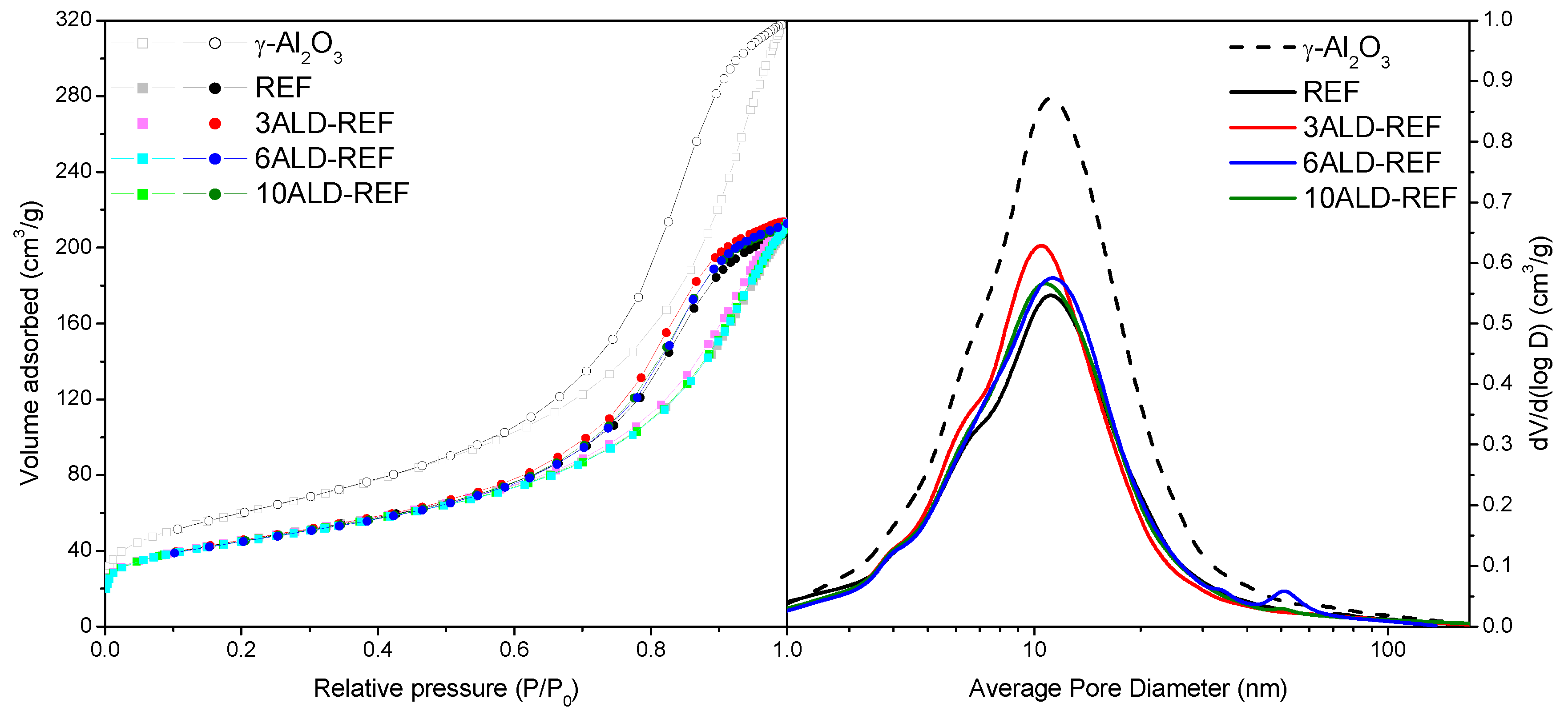
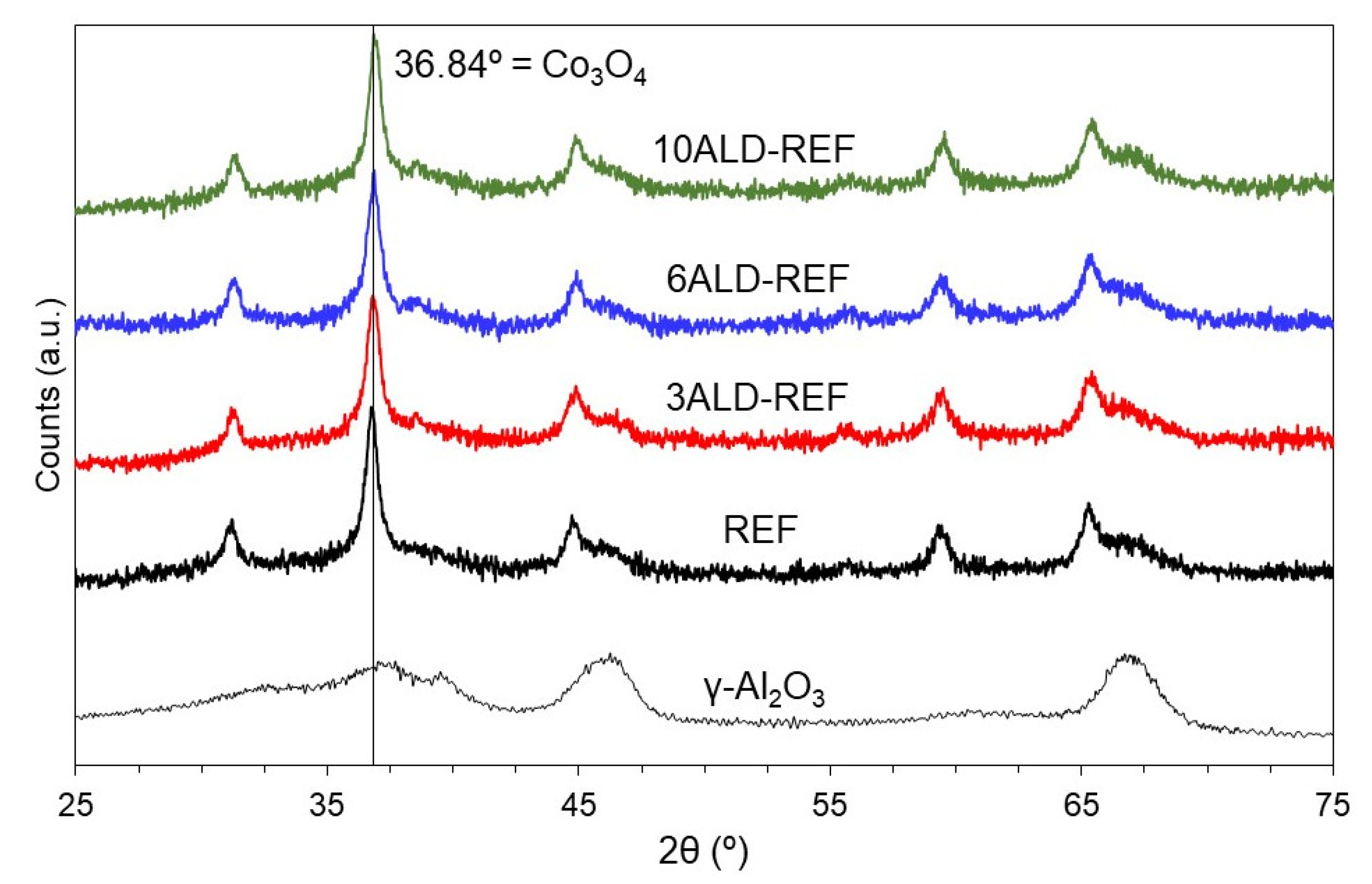
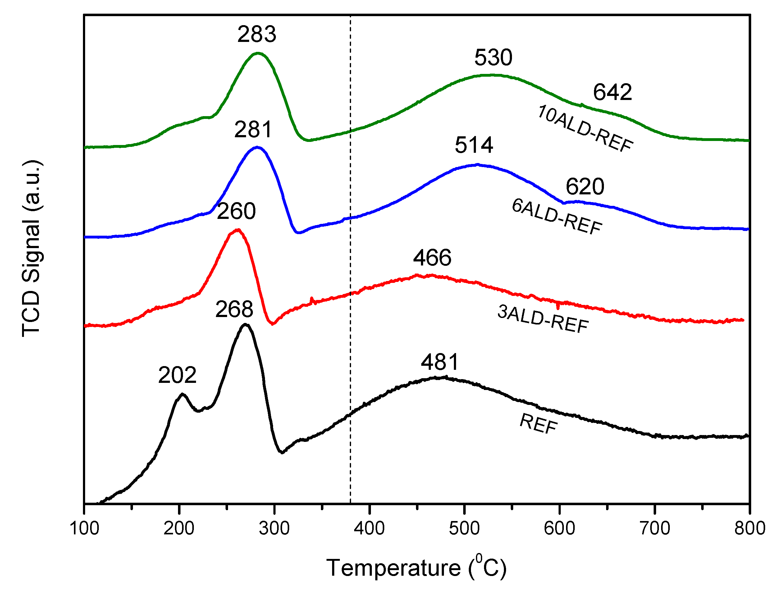
Figure 1. N2 adsorption-desorption isotherms (left) and mesopore size distribution (right) of all samples.
Catalysts 11 00732 g001
Figure 2. XRD diffractograms of support, REF and ALD-coated samples.
Catalysts 11 00732 g002
Figure 3. TPR profiles of REF and ALD-coated samples. Dashed line indicates the reduction temperature selected.
Catalysts 11 00732 g003
Figure 4. Low magnification TEM micrographs of samples REF (left panel), 3ALD-REF (central panel) and 10ALD-REF (right panel).
Catalysts 11 00732 g004
Figure 5. STEM-HAADF images of REF (left panel), 3ALD-REF (central panel) and 10ALD-REF (right panel).
Catalysts 11 00732 g005
Figure 6. STEM-EELS maps of REF (left panel), 3ALD-REF (central panel) and 10ALD-REF (right panel). Composite Co-Al-O maps and single element maps are reported. On the right side of the element map, the atomic relative composition maps are also reported.
Catalysts 11 00732 g006
Figure 7. Activity vs. TOS of catalysts studied at regular conditions.
Catalysts 11 00732 g007
Figure 8. Activity vs. TOS of catalysts studied at accelerated deactivation conditions.
Catalysts 11 00732 g008
Table 1. Main catalyst properties obtained by characterization.
SampleBET Surface Area (m2/g)Pore Volume (cm3/g)TPR-Tmax (°C) aCo Crystallite Size (nm) bExtent of Co Reduction (%) c
γ-Al2O32160.492---
REF1630.320268/48112.461.4
3ALD-REF1630.331260/46611.656.5
6ALD-REF1610.322281/51411.165.4
10ALD-REF1610.327283/53012.111.1
a TPR: Co3O4 → CoO/CoO → Co0. b XRD: obtained with the Scherrer formula, from the Co3O4 reflection at 36.8° and the equation dCo0 = 0.75∙dCo3O4. c O2 titration: assuming complete oxidation of Co0 to Co3O4 as theoretical.
Table 2. Experimental results (reaction conditions: 20 barg, 230 °C, 8400 NmL/g∙h, H2/CO = 2/1 (mol/mol)).
SampleTime (h)XCO (%)Selectivity (%) A ( t i ) A r e f ( t i ) Y C 5 + ( t i ) Y C 5 + r e f ( t i )
CH4CO2C2–C4 aC5+
REF1643.515.90.704.7878.611
8735.914.90.5911.673.011
3ALD-REF1743.017.20.765.276.90.9900.967
8736.715.20.5710.973.31.0181.026
6ALD-REF1740.115.30.747.676.30.9450.895
6434.814.00.6611.573.90.972 b0.981
10ALD-REF1528.132.10.789.957.20.7060.470
6230.221.20.6212.266.00.860 b0.760
a Sum of C2H6, C2H4, C3H8, C3H6 and C4H10 concentrations. b Aref: activity value of REF at the same time as this sample (64 and 62 h, respectively).
Table 3. Deactivation rate parameters for 0th, 1st and 2nd order GPLE’s.
Deactivation Order012
Sample k d   ( m i n 1 ) r 2 k d   ( m i n 1 ) r 2 k d   ( m i n 1 ) r 2
REF2.38 × 10−40.80212.63 × 10−40.81542.92 × 10−40.8279
3ALD-REF2.02 × 10−40.84962.20 × 10−40.86192.41 × 10−40.8735
6ALD-REF1.73 × 10−40.73841.90 × 10−40.75282.07 × 10−40.7665
Table 4. Experimental results (reaction conditions: 20 barg, 230 °C, 4800 NmL/g∙h, H2/CO = 2/1 (mol/mol)).
SampleTime (h)XCO (%)Selectivity (%) A ( t i ) A r e f ( t i ) Y C 5 + ( t i ) Y C 5 + r e f ( t i )
CH4CO2C2–C4 aC5+
REF1756.813.60.875.3380.211
10047.612.50.5410.376.711
20044.512.60.5310.776.211
3ALD-REF1756.714.90.965.6478.51.0140.977
10047.712.40.5610.077.01.0111.001
20044.812.30.5110.376.91.0131.016
6ALD-REF1756.816.31.086.7275.91.0120.946
10048.414.10.7010.874.41.0290.986
20045.713.40.5810.775.31.0341.015
a Sum of C2H6, C2H4, C3H8, C3H6 and C4H10 concentrations.
Table 5. List of the samples studied in the present work.
Reference SampleNumber of ALD CyclesNomenclature
16Co/γ-Al2O3
(Johnson Matthey)
0REF
33ALD-REF
66ALD-REF
1010ALD-REF
Publisher’s Note: MDPI stays neutral with regard to jurisdictional claims in published maps and institutional affiliations.

