1. Introduction
3D printing technologies, known broadly as additive manufacturing (AM) processes, fabricate three-dimensional structures from CAD files by adding successive layers of materials. The emergence of advanced digital technologies has led building construction practitioners to rethink the cost- and resource-effectiveness of their productivity, and make decisions towards adopting new technologies [
1,
2,
3]. Many industries—from manufacturing to medicine—have made use of 3D printing technologies since the 1980s. However, architectural practices and the construction industry have only recently begun to adopt these technologies for construction [
4].
3D techniques can be described in terms of four main manufacturing processes: (i) subtractive manufacturing; (ii) additive method (rapid prototyping); (iii) forming techniques; and (iv) hybrid methods. Subtractive manufacturing refers to cutting technologies that remove undesirable parts of objects using CNC (Computer Numerical Control) machines or similar tools. AM refers to the addition of materials to an object or the creation of a new object from design in the absence of human intervention. Forming techniques involve the reshaping of objects without reducing or adding materials, and hybrid manufacturing processes involve a combination of the best features of both subtractive and additive techniques [
5].
3D printing, which is the focus of this paper, was first associated with a specific AM process. AM is now widely recognised as a disruptive technology that could transform the construction industry, with 3D printing technologies and materials reconstructing traditional manufacturing methods, whether in a revolutionary or evolutionary way.
3D printing, as a technique for constructing matter, has become popular in recent years. Using a virtual and digitally constructed 3D design model as its blueprint, it sequentially lays down layers of material until the envisaged physical object has been created. The technique is cost effective and saves time. When compared with traditional concrete construction, it saves on labour costs and offers a higher curing rate, due to the nature of the materials used. Various additive manufacturing techniques (e.g., extrusion, jetting, sheet lamination, and photopolymerisation) are used to fabricate light-weight and large-scale composite products that combine polymers and fillers (e.g., carbon fibre, glass, CNTs (Carbon nanotubes), etc.) [
6,
7,
8]. These are highly efficient for manufacturing, and minimise both costs and waste. Thermoplastics used in the process include polyethylene, polypropylene, polycarbonate, polyvinylchloride and acrylonitrile butadiene styrene (ABS).
There exist a variety of automated additive manufacturing methods but, among them, 3D inkjet printing has proved to be highly efficient. It draws from different computer-design morphologies (e.g., 2D or 3D), offers a continuous extrusion process, and has the capacity to cure areas designed in polymer/filler suspension. 3D printing has been used to build such functional components as large buildings, car products, medical devices (human tissues, organs, and dental material) and wearable gut. It also has applications in other branches of production, and the manufacturing of acoustic and vibration products.
The potential advantages of AM in housing are significant. They include not only improved efficiencies pertaining to the environment and financial resources but, also, the capacity to customise designs for aesthetic and structural applications to increase architectural freedom. Previous studies suggested drivers for automation, and digital technology adoption includes an improvement in productivity and safety, and a reduction in construction costs and time [
9,
10,
11]. Many recently completed projects—such as Contour Crafting in the United States, Apis Cor in Russia, and Winsun in China—have provided evidence that the 3D printing of houses can be realised on various scales, and AM technologies offer innovative solutions for affordable housing construction.
While various scholars have described the benefits of AM, “rapid building prototyping” (RBP) practices have not been sufficiently explored from a construction perspective. The construction industry is complicated by the variety of building components created: their sizes, quality, and safety, and their strength as used in different projects. Scholars must, therefore, extend their RBP practices to different scales in the laboratory, and on actual construction sites. This study applies a structural analysis perspective to the design of a roof prototype that uses particular materials.
Recent studies have tended to develop and apply frameworks to test the performance of fresh printing mixtures in the laboratory [
12]. Such studies have tended to create small prototypes of building designs to understand potential challenges and deficiencies associated with RBP. This project aims to analyse the structural feasibility of a 3D-printed building prototype by using the finite element software Strand 7. It also investigates the feasibility of building a 3D-printed house prototype.
Previous studies have generally looked at 3D printing in different contexts, and presented the technology’s advantages. However, its practical limitations—for example, its inability to produce steel bars and other complicated building elements—have not been fully investigated. Overall, its advantages include layer-by-layer deposition, which negates the need for formwork, and moulds that lead to a reduction in construction waste. Highly accurate placement means that materials can be considered as more efficient materials for construction. However, previous studies have failed to fully introduce and investigate replacements for steel, particularly from a practical perspective. In situ 3D printing has the potential to cut transport costs, energy consumption, and pollutant emissions, as well as injuries and fatalities [
13]. However, such potential benefits should be evaluated in the contexts where they are critical to practitioners. Furthermore, while construction companies use a variety of material mixes—including cement, steel, and fibres—and 3D printing has the capacity to introduce multi-material deposition, including different percentages of plastics and fine materials, there is insufficient evidence to show that all construction materials can be mixed and used by 3D printers. This is of significant importance, since variations in the material composition at different stages of a print could reduce material use if it is not structurally required.
This paper aims to demonstrate that the combination of highly efficient materials with recycled waste products, in the formation of structural housing elements, is desirable, saving construction companies costs while protecting the environment by introducing waste solutions. In addition, the paper uses laboratory 3D printing to examine a smaller scale of its proposed roof elements for the feasibility of their shape stability. Although the process is simple, it is efficient enough to provide solutions for remote areas, where supplies and skilled labour can be hard to come by.
For a range of high-end applications, such as 3D-printed buildings and products used in the aerospace and automotive industries, it is essential to understand the mechanical properties of materials [
14,
15]. Mechanical properties pertain to a material’s ability to withstand applied loads and displacements. Underlying these properties is a constitutive law that relates the strain experienced by the material to an applied stress. This strain is measured using tensile tests: a sample is loaded with tension, and the strains are measured as a function of applied stress to determine such properties as stiffness, strength, ductility, and toughness. Stiffness relates to the elastic modulus and defines the force required to produce elastic deformation. Three factors are critical to the design of novel, high-strength materials: chemical composition, nano/microstructure, and architecture.
Various materials have been used in 3D printing for a range of applications. Kazemian et al. [
12] used a mixture of cementitious materials and nano-clay, or polypropylene fibre or silica fume, to study the workability of such 3D-printed mixtures on a construction-scale project in terms of print quality, shape stability, and printability window. Another concrete printing machine consisted of a 5.4 m × 4.4 m × 5.4 m frame, and a printed head on a movable horizontal-beam that shifted in the Y and Z directions while the printing head moved only in the X direction [
9,
16], and time-dependent structural build-up of cement materials in a layer-by-layer construction process [
17]. A fibre/cement mixture (cement content: 827 kg/m
3) was used to print a 2 m concrete bench with the compressive strength of 110 MPa, and the shear strength of 0.3–0.9 kPa [
18]. Rushing et al. [
19] tested the physical properties of components developed from 3D printing by applying extruder testing, drop table tests, compressive strength, and flexural strength. Furthermore, various mixed concrete materials (e.g., fillers, wood fibres, polymers, and geopolymers) have been used to print 2D and 3D components for building applications [
20,
21,
22,
23,
24,
25]. Nakagawa et al. [
26] used the technique to fabricate 3D products using carbon fibre (tensile strength: 5.3 GPa) combined with ABS (tensile strength: 30 MPa) and without cement. However, limited work has been carried out on the printing of 3D building materials that use polymer/nanocarbon-based composites.
In December 2016, one 3D house printing manufacturer [
27] successfully utilised mobile 3D printing technology to create the first house printed solely from 3D printed materials. It was built on site in Moscow, with a pure machine printing time of 24 h and a cost of
$10,000, as stated by Apis Cor [
27]. The area of the printed build was only 38 m
2—it aimed to serve as a capability showcase—but the time it took, and the total cost, were extremely advantageous when compared with traditional methods. Since such 3D-printed buildings arise from the implementation of an innovative technology to construct a physical model, making use of a relatively new method rather than traditional practices, they are not yet common place.
At the time of writing this report, there were no strict guidelines or related Australian standards for the design of 3D-printed buildings. As a consequence, the functions and limitations of 3D printing in construction are closely linked to a contractor’s knowledge. Existing Australian standards for structural strength, however, provide a reliable guide to the design of structural integrity in a modelled structure. In particular, AS1170 and AS3600 can be used as design guidelines.
This paper begins by reviewing the literature and categorising advances in and applications of AM. Second, it presents a specific roof prototype and discusses various materials before analysing the designed prototype with the structural analysis software Strand 7. Third, the paper uses virtual information and converts it into a physical object that represents the roof. Finally, the paper discusses the lessons learnt and the challenges to this mixed design-built practice on a laboratory scale. It also suggests future directions.
4. Results and Discussion
4.1. Numerical Modelling
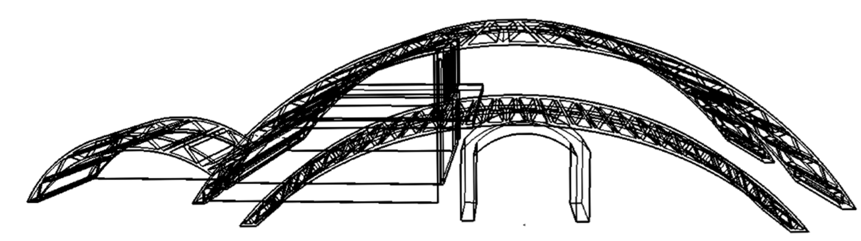
Finite element software, Strand 7, was used to conduct a numerical analysis of the design structure that is the subject of this paper. The overall structure consists of multiple arch roofs that contain triangular voids. These form a truss-like structure inside the arch roofs, taking advantage of the transfer of loads within a truss structure and reducing self-weight. Smaller sized triangular voids at the end of the structure provide greater strength while reducing the possibility of buckling.
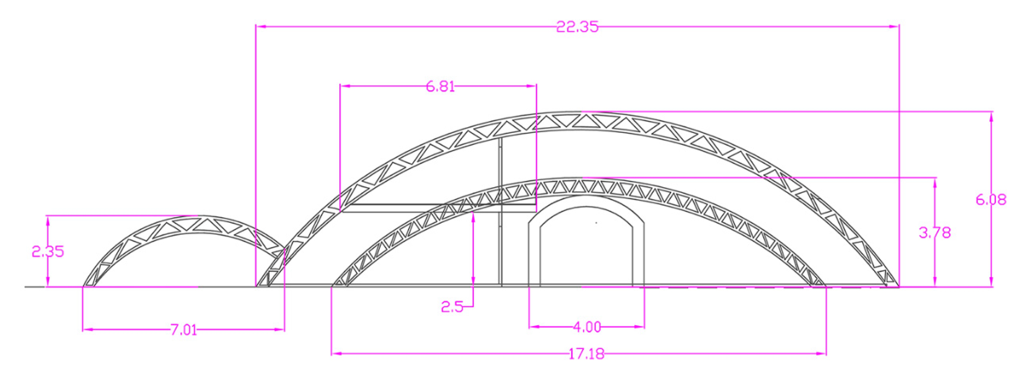
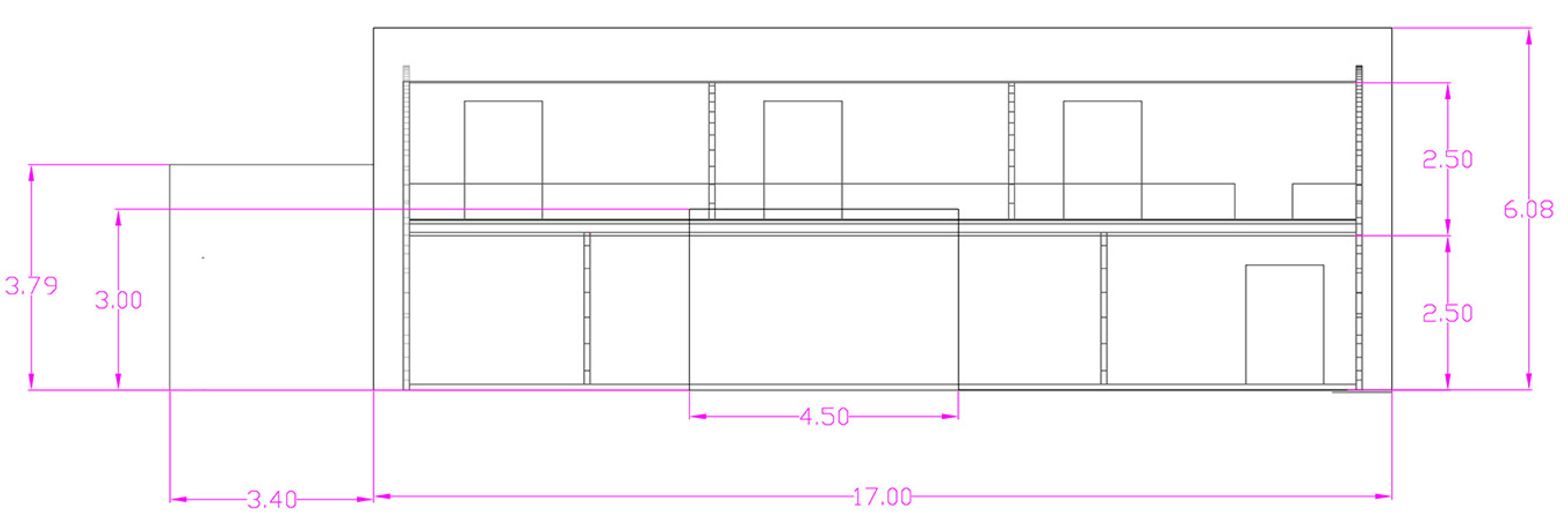
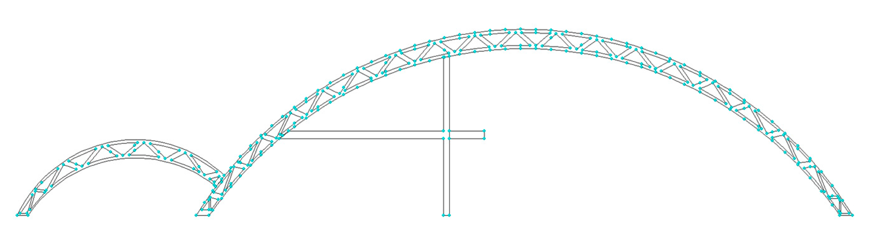
The front elevation of the model was first constructed in AutoCAD, due to the structure’s complexity. The roof consists of multiple triangular voids within a curved arch. This is impossible to model by hand with regular square elements in Strand 7, so the structure was first modelled as a 2D vector model in AutoCAD. The 2D model was constructed by following the dimensions in
Figure 7. The resulting model was imported as a dxf file, and into Strand 7 as a face element. This face element is shown in
Figure 8. It shows the main arch roof, the side arch roof, the garage, the shear walls within the main roof, and the first-floor slab.
Next, the auto-meshing function of Strand 7 was adopted to create the best mesh for the model, as computed by Strand 7. The mesh sizes were controlled to generate mesh within a dimension of less than 0.15 m so as to increase the accuracy and converge the numerical result. Quad 4 elements and Tri 3 elements were used in generating the front face shell elements. Then, the shell elements were extruded to brick elements, with the same length increments as the dimensions of the Quad 4 elements. After obtaining the 3D model that was formed by brick elements, further modification was made within Strand 7, including the design of door and window openings, constraints for the base supports, defining material properties of the concrete–rHDPE mixtures, defining loads and load combinations, etc.
4.2. Load Combinations
The combination of actions used to design this 3D-printed house would satisfy the load combinations outlined in AS1170.0 [
33]. The house was designed to the ultimate limit states that are used for checking stability, with the following combination factors given in AS1170.0 [
33] Clause 4.2.1. Note that, as this structure is assumed to be located in the Sydney area of Australia, the significance of earthquake load is minimal. According to AS1170.4 [
33] in domestic housing structures with heights under 8.5 m, or an importance level of 1, the significance of earthquake load is outweighed by other loads. As a result, any earthquake load imposed on the structure is not included in this analysis. In the following load combinations, the symbol G represents permanent action, Q represents imposed action, and W
u represent wind action. These are the load combinations used in Strand 7 to check the structural design action as stated in the Australian Standards:
1.35G
1.2G + 1.5Q
1.2G + Wu + 0.4Q (positive wind)
1.2G + Wu + 0.4Q (negative wind)
0.9G + Wu (positive wind)
0.9G + Wu (negative wind)
4.3. Gravity Load
Self-weight is defined as the weight of the structure itself, and was calculated by including gravity in the load combination. The density of the brick elements had to be defined, as well as the concrete–rHDPE mixtures. The density of the mixture is slightly less dense—at 2380 kg/m
3—due to the addition of rHDPE fibres, than typical concrete mix, which has a density of 2400 kg/m
3. In Strand 7, 9.81 m/s
2 is taken as the acceleration due to gravity in the Z direction.
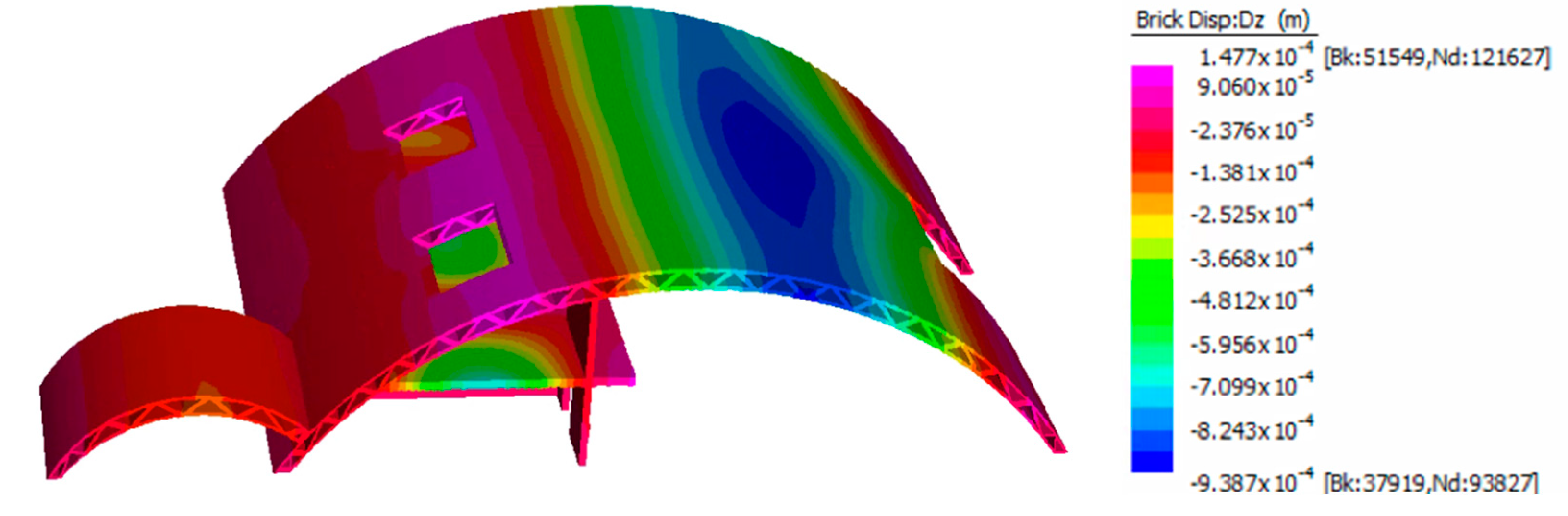
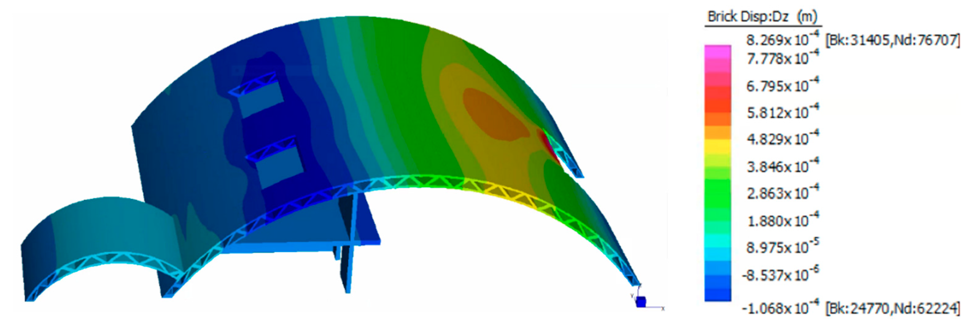
Figure 7 is a graphical representation of the displacement scale of the structure purely due to gravity load.
The overall loading effect, in this case, is owing to self-weight, which includes gravity and is vertically downwards. The contour shows that maximum deflection occurs in the main roof, near its right-hand side. This is due to the large opening and lack of support from shear walls. The large opening in the right-hand side of the roof, which forms an entrance to the garden from the house, may also contribute to this deflection. However, the deflection is at a minimum, at only 0.94 mm, and falls within the acceptable range according to AS3600 [
34]. Although there are window openings on the left-hand side of the roof, this area does not seem to experience concentrated stress because it is well supported by the shear walls, in accordance with the design decision. This dead load is used at a later stage as a loading combination in accordance with AS1170.0 [
33].
4.4. Imposed Action
Imposed action is the sufficient allowance for vertical impacts that arise from the usual movement of people and shifting of furniture. In accordance with AS1170.1 [
33], the designed location is defined as Group A1 (domestic and residential activities, self-contained dwellings). The imposed action for Group A1 should satisfy the follow requirements.
For the ground floor, the imposed action shall be designed as a uniformly distributed action of 1.5 kPa, or concentrated action of 1.8 kN if the area is greater than 320 mm2, for the calculation of punching and crushing shear. Since the house has a ground floor of 374 mm2, both the uniformly distributed action and the punching/crushing shear will be considered in the calculations.
For the first floor, the imposed action shall be designed as a uniformly distributed action of 1.5 kPa, or a concentrated action of 1.8 kN if the area is greater than 320 mm2, for the calculation of punching and crushing shear. Since the first floor has an area of 102 mm2, calculation of punching/crushing shear is not required.
For the stair area, the imposed action shall be designed as a uniformly distributed action of 2.0 kPa, or concentrated action of 2.7 kN.
For the non-habitable roof space, the imposed action shall be designed in accordance with AS1170.1 [
33]. Since the roof is defined as R2—a roof that uses structural elements—the uniformly distributed actions shall be calculated as:
However, the uniformly distributed load shall be no less than 0.25 kPa. Since the area projected by the roof is 379.46 m
2:
Therefore, the imposed action shall be taken as 0.25 kPa. It shall also satisfy a concentrated load of 1.4 kN for the requirements of punching/crushing shear.
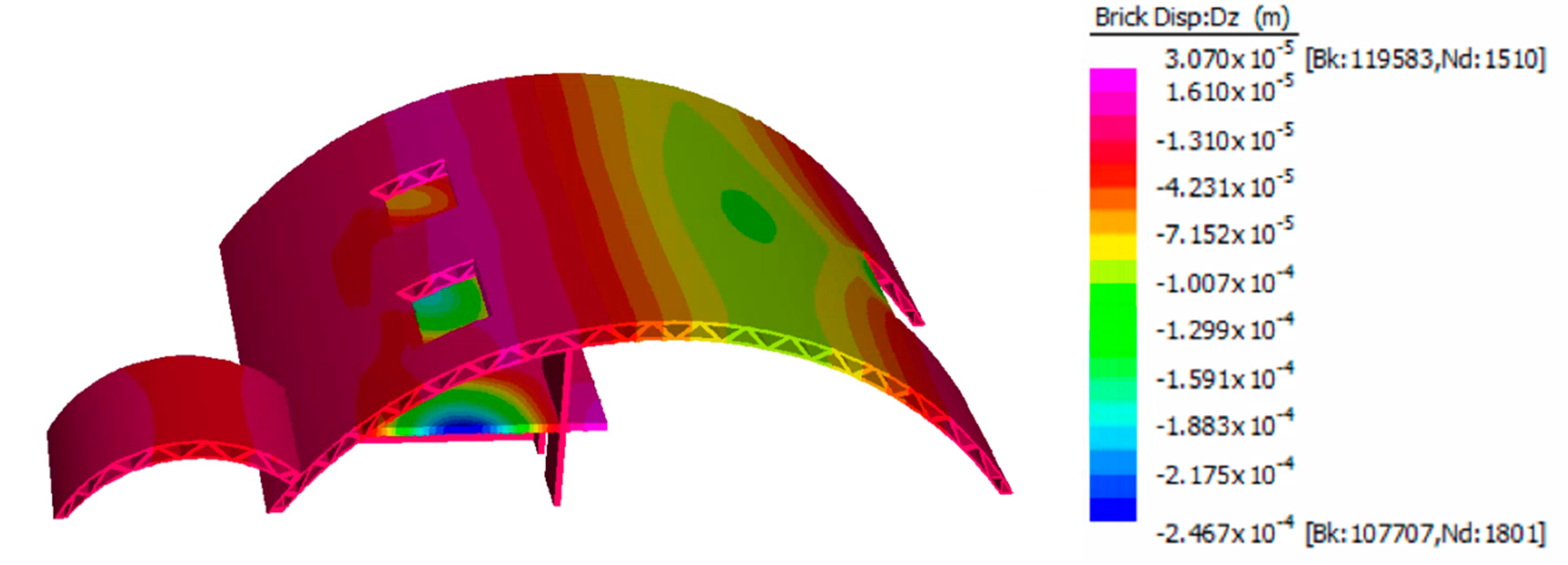
Figure 9 is a graphical representation of the stress contour of the structure after all imposed action had been incorporated into Strand 7.
The live load areas are defined as concentrated only in habitable areas (i.e., the floors and first-floor slab), with minimal loadings in inhabitable areas (i.e., the arch roofs). Therefore, the deflection contour due to imposed action shows a different profile when compared with the deflection due to dead load in
Figure 9. The maximum deflection occurs within the first-floor slab, with a value of 0.25 mm. The differing nature of both load cases is due to the way AS1170.1 [
33] defines imposed action according to an allowance of the effects of vertical impact from live load. The deflection by imposed action is minimal, and within the acceptable range. The difference in load concentration area is advantageous to prevent loadings concentrated at a single spot during load combinations with dead loads. This load case is used at a later stage for the load combinations.
4.5. Wind Load
The 3D-printed house was assumed to be located in the Hornsby area of Sydney for the sake of load analysis. Therefore, in accordance with AS1170.2 [
33], it would be classified as Region A2. It was assumed that the topography was flat, and there was no shielding effect. The building was in terrain category 3. The dynamic response factor for such a building was conservatively taken as 1.0. For the designed build, there exists a large door on the west side with dimensions of 4.5 m wide and 3.06 m high. There are also three windows on the east side, with dimensions of 2 m by 2 m.
The building was designed to face a wind event with an average recurrence interval of 500 years. It was designed for wind from a northerly direction. Area reduction and combination factors were ignored, and taken as 1.0 for ease of calculation, and as part of a conservative approach.
First, the design wind speed needed to be established from the given data. The design parameter of the roof height is 6.08 m. For Region A2, the wind average recurrence V500 = 45 m/s. For wind coming from the north, the critical Md is 0.95 from a northwesterly direction. The terrain multiplier Mz,cat was taken as 0.83 for a roof at 6.08 m within terrain 3. Therefore, the designed wind speed was taken as
The wind speed at full roof height should therefore be taken as 39.76 m/s. For the external wind pressure, it should be calculated in accordance with AS1170.2:2002, where for an arch roof with r/d = 3/22 = 0.14:
Therefore, the external pressure
p is found by
where
, and
shall be taken as 1.0 for the most conservative case. Therefore,
For the leeward wall, for d/b = 17/22 = 0.77,
Cp,e is taken as −0.5. Therefore, leeward wall pressure is calculated as
For side wall pressure, in accordance with
Table 3, pressure differs according to the location of the wall, with consideration of the maximum roof height.
Table 3 summarises the wall location and its corresponding wind pressure.
Figure 10 shows the graphical representation of the displacement scale of the structure due to wind load. The deflection contour due to wind load shows a different profile when compared with the other load case. The main difference is that wind loads are applied perpendicular to the surface of the roof, instead of being a vertical load. Wind loads are only applied on the roof, and not on the shear walls or first-floor slab. Therefore, the loading effects are higher in areas that are exposed to the outer environment which, in this case, are the arch roofs. Maximum deflection occurs at the main roof slab, with a value of 0.11 mm. This is the least out of three of the load cases, which is intuitive since wind has a minimal effect on low-rise buildings. Wind loads will often be a concern only in high-rise buildings. This load case is used at a later stage for the load combinations.
4.6. Load Combination Result
All six different loading combinations in accordance with AS1170.0 [
33], with different multiplier factors, were fed into Strand 7 and compared.
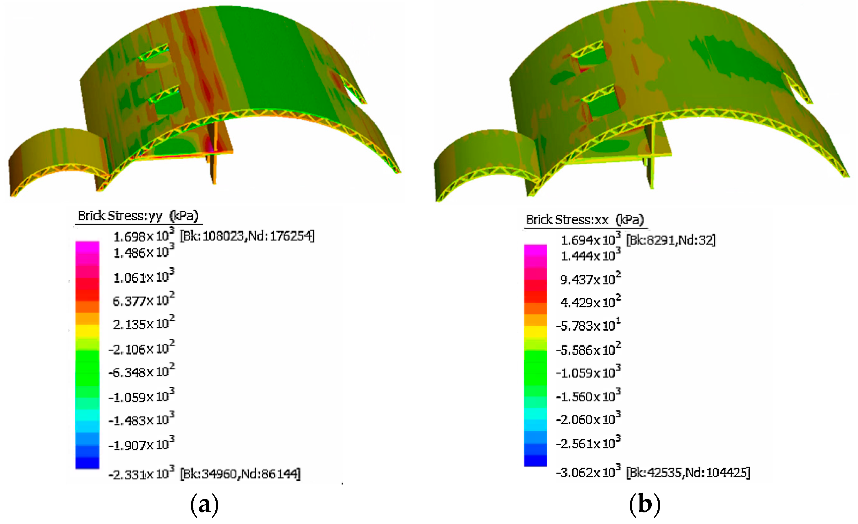
Figure 11 shows the resulting stress bar for the maximum tensile and compressive stresses that the structure experienced among all load combinations. Both are from a load combination of 1.2G + 1.5Q, where
Figure 11a shows the stress in yy and
Figure 11b shows the stress in xx directions. Both figures also include the contour for inspecting the load concentration point among the building’s design. As stated previously, the minimal effect of wind loadings arises because low-rise buildings expose a limited surface area, and there is minimal wind speed at a low height. The resulting critical load combination case is, therefore, one without wind loadings, and its influence is minimal.
Note that the maximum tensile stresses in both xx and yy directions are very similar, and differ by less than 0.01 MPa. The maximum tensile stress in yy direction is 1.698 MPa and, in xx direction, is 1.694 MPa. Those two values are less than the tensile characteristics of the concrete–rHDPE mix used for the structure, which exceed 2.8 MPa in tensile strength. The maximum compressive stress among all load combinations, on the other hand, is 3.063 MPa, which is significantly smaller than the compressive characteristic of concrete mix, at 26 MPa. Therefore, the structure would withstand the load combinations that a typical house would experience, according to AS1170 [
33]. As shown in
Figure 11a, the concentration of stress is mostly along the first-floor slab and the roof, which are sufficiently supported by the shear walls near the middle. If not for the shear wall in the middle, which allows for the large roof span, the numerical result might have been different, and exceed its tensile strength due to an unsupported span. The use of rHDPE mix is, again, highly advantageous because it increases the tensile strength of the concrete and enables it to withstand most of the tensile stress without the addition of reinforcements.
4.7. Structural Design
It was in our best interests to investigate the benefits of adapting an arch design for this 3D-printed house. A limiting factor of this project was the inability to use a reinforcement bar within the cement mix. Therefore, arch design comprised the main design concept because of its ability to reduce tensile stress. Hand calculations of the main arch roof were performed, as well as an analytical estimation of arch-like structures [
32]. The calculations assessed the behaviour of the arch under gravitational line loads, with the use of the small angle theorem among other assumptions. Dym et al. [
32] discussed the underlying assumption while performing this analytical solution. The main analytical method used for this report is noted, with
Figure 12 showing the parameters required. An arch is defined by radius
R and semi vertex angle
α by design. The parameter q represents the force per unit length,
z represents the roof height,
v and
w the force vector along the arch, and theta
θ the angle along the arch.
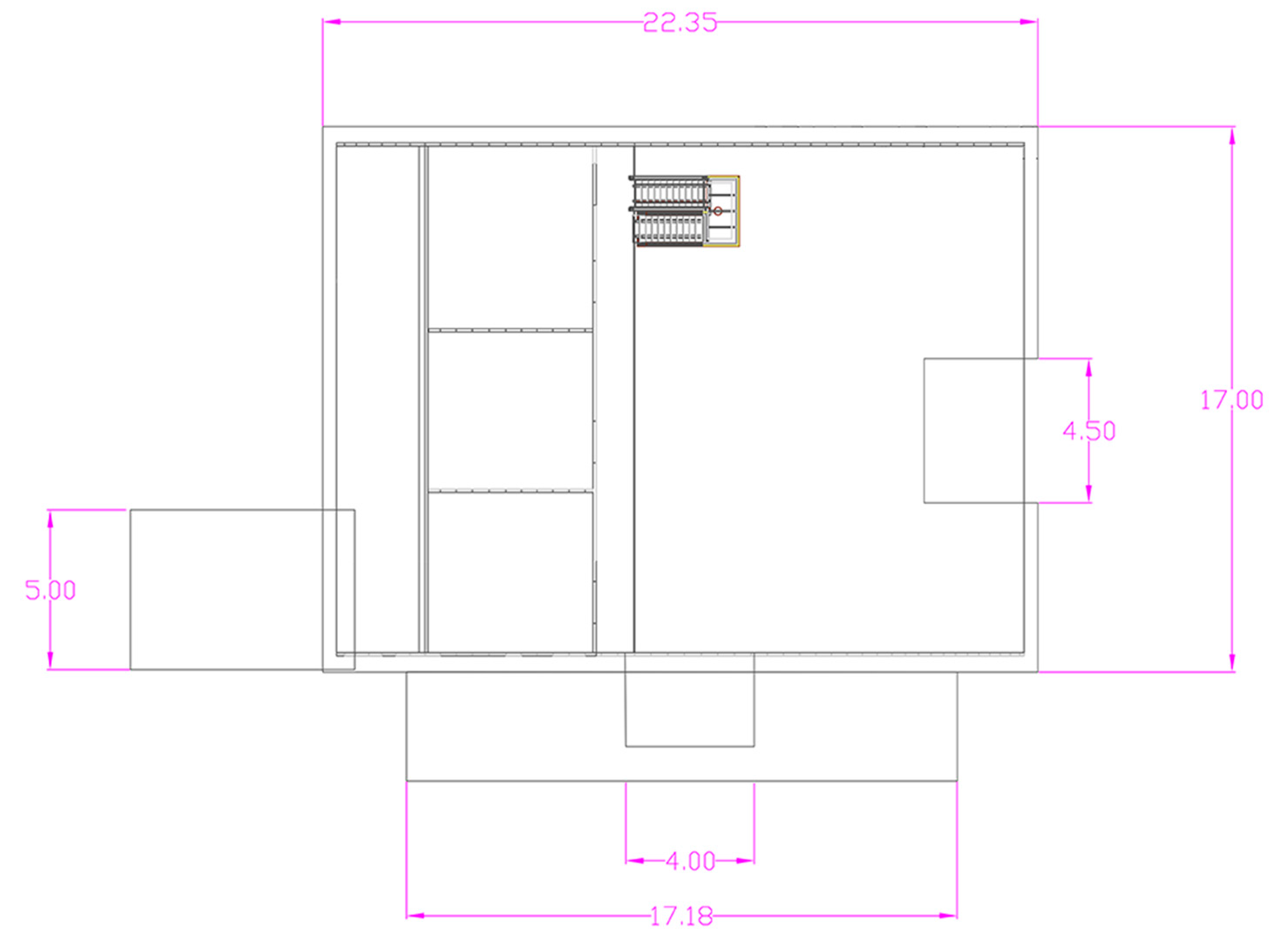
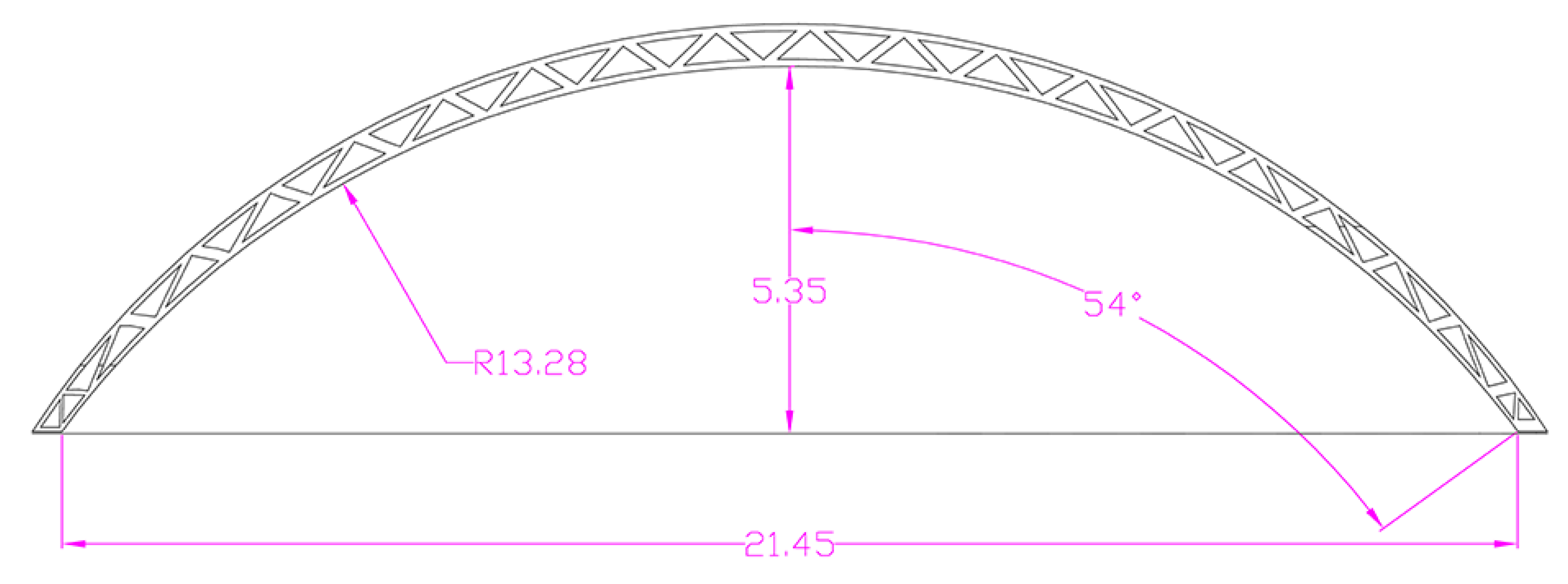
Figure 13 shows the design parameters for the roof arch of the 3D-printed house. The truss-like voids within this arch were not considered in the hand calculations (the arch is assumed to be fully filled as a solid concrete roof). Therefore, the gravity load for the roof would be overestimated in this hand-calculation, and over-conservative. It should also be noted that the depth of the roof is 17 m, as per the design in the 3D model within Strand 7 (
Figure 13).
From the analytical formula by Dym et al. [
32], the arch rise parameter λ is given by the ratio of the roof rise as
and the moment resultant along the roof arch is given by
By substituting the arch rise parameter
λ, the bending moment can be obtained.
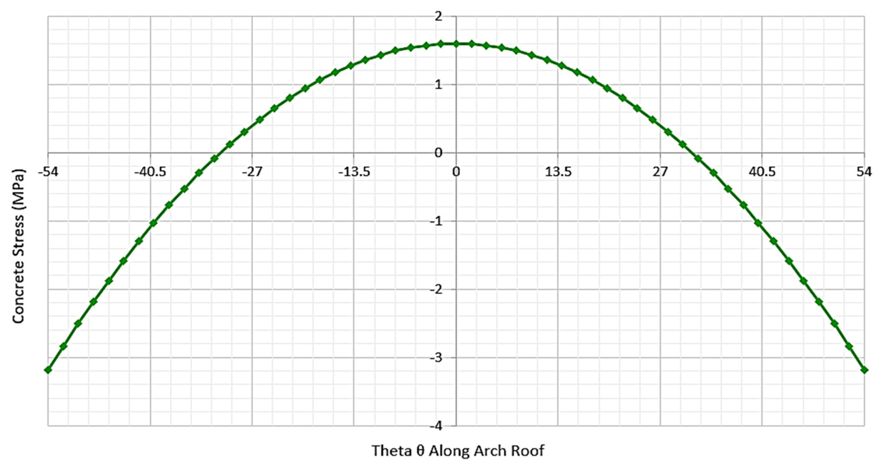
Figure 14 shows a plot of the bending moment stress along roof angle
θ. The roof is mostly subjected to compressive stress along the two roof-ends, with the middle subjected to tensile stress. The maximum tensile stress is about 1.6 MPa, which the concrete roof can withstand because the 3D-printed house uses a concrete–rHDPE mixture that has a tensile characteristic of 3.0 MPa. Therefore, the concrete required no reinforcement. This result is consistent with the numerical analysis from Strand 7, where the maximum tensile stress experienced by the arch roof was found to be 1.69 MPa. Note that the referring result arose from a load combination instead of a pure dead load by the roof. However, since this hand calculation assumed a solid roof-slab, rather than a roof full of truss-like voids, the result of the hand calculation should be taken as an overestimate of the bending stress experience by the roof itself (see
Figure 14).
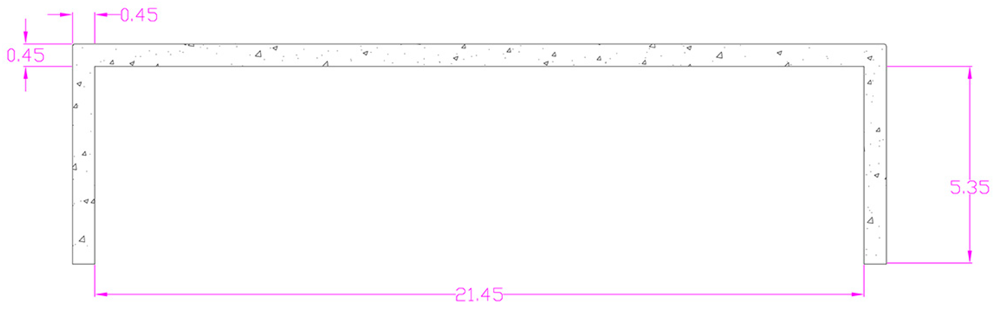
This result was compared with a traditional flat-slab roof for the purposes of investigating and comparing the benefits of using an arch roof in this design. A typical flat-slab roof is used for this calculation to find the maximum bending moment within the roof slab.
Figure 15 shows the typical setup of a flat-slab roof with the same dimensions (width and height) as the arch roof. The width of the roof and column are the same as the arch roof.
The calculations for finding the bending moment within the flat-slab roof are performed using the simply supported beam theory, with each end of the slab assumed to be pin-jointed. The formula for the stress along the slab, at distance
x, is given by the analytical solution of
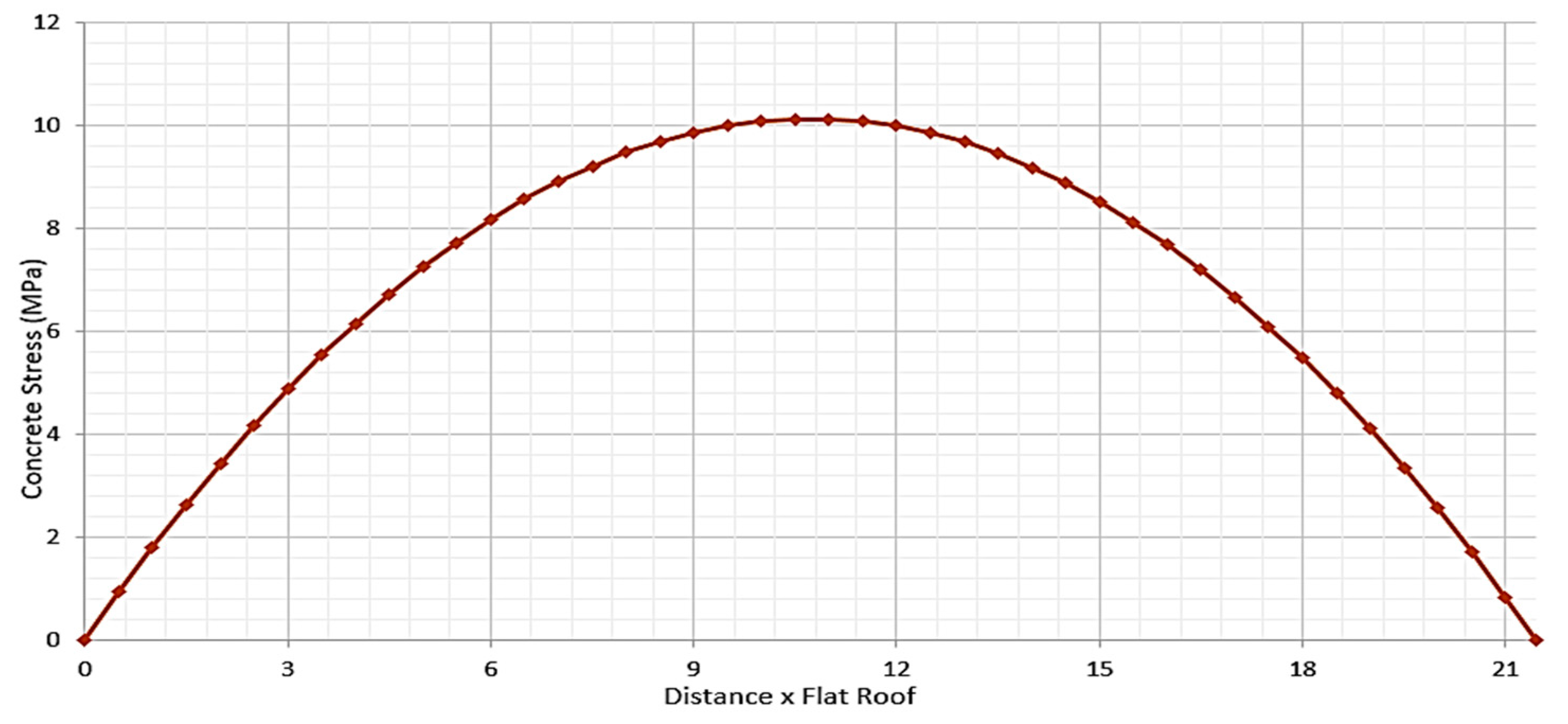
The plot of bending stress along the slab is shown in
Figure 16. The tensile stress is higher than that of the arch roof. The maximum bending stress that the flat-slab roof can experience is 10 MPa at the middle of the roof. This result was expected since the flat slab would have maximum sagging in the middle, particularly in the absence of any support. The long span of the roof induced an excessive tensile stress that was much greater than the tensile strength of the concrete–rHDPE mixture, which is only 3 MPa. Such high tensile stress in the middle of the flat slab is typically acceptable in traditional reinforced concrete. However, for this 3D-printed house, the excessive tensile stress does not suit the cement mix in the absence of reinforcement. Therefore, a flat-slab roof design is not suitable for 3D-printed housing. The excessive tensile stress would cause the concrete to fail.
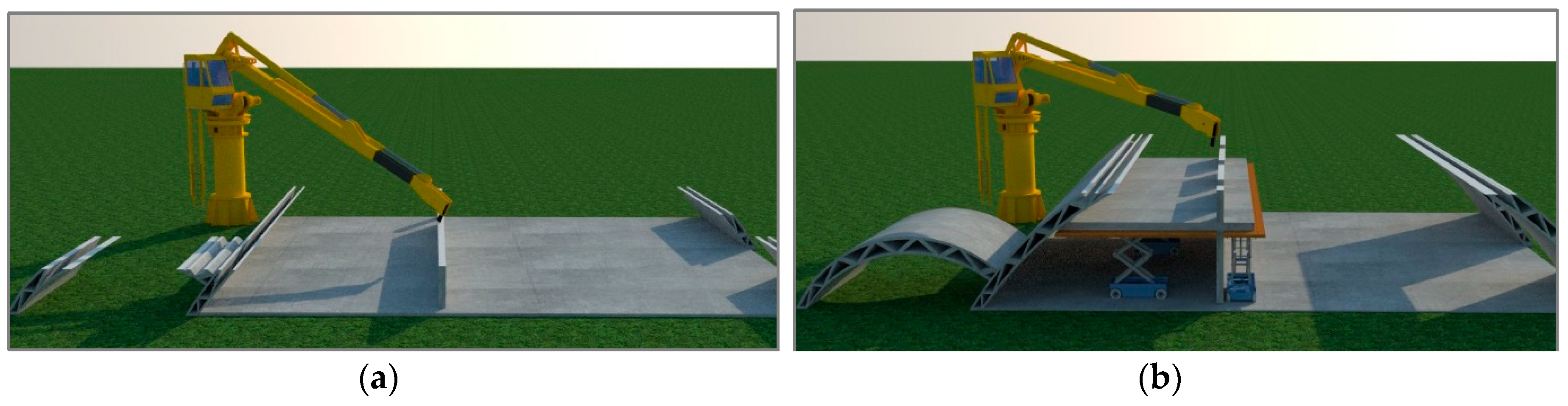
Special attention was devoted to preparing and assembling the numerical models developed using 3D printing. Initial preparations, which included drafting the relevant executive sketches of the roof as well as other members, were undertaken, with precision, in AutoCAD. The prepared AutoCAD files were considered AS input files for the 3D printing machine.
4.8. Structural Design
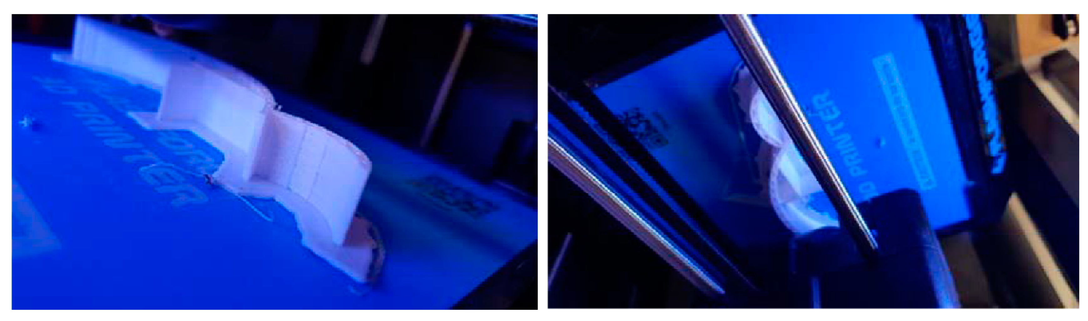
Figure 17 illustrates different stages in the creation of the 3D model. As presented, different elements of the roof were added, step by step, to the initial elements, to complete the drafted curved roof. Further details can be seen in
Figure 18. One of the main contributions of the current paper is to display the capacity of 3D printing techniques to create structural details, including diagonal and bracing members that are available in the developed numerical models.
5. Discussion
This study contributes to the design of a numerical model that uses a cement mix material combined with the recycled waste product HDPE. It differs from previous studies in two ways. First, the presented design procedure and analysis of an arched truss-like roof has been carefully analysed to evaluate the feasibility of constructing this case, complicated by the need for steel reinforcements and specific shape requirements. This paper shows that the limitations of 3D printing, through which it is not easy to produce steel bars in situ, can be addressed by making use of HDPE materials. Second, the paper analysed the shape stability of this design, and a small-sized model was developed to evaluate its feasibility.
With the application of Strand 7 Finite Element Analysis, it was found that the construction efficiency could be increased, and the overall building costs would fall as a result of implementing the designed material and 3D printing. Strand 7 software was used because it is commercially common in the Australian region, and previous 3D printing studies had ignored both its use and Australian standards in their analytical methods. This had raised uncertainties about the use of 3D printing in practice in this geographic region.
The specific roof design presented in this paper for a 3D-printed building was also used to manufacture a prototype for further laboratory testing of shape stability. Shape stability was a major criterion suggested by a recent publication for the laboratory testing of fresh printing mixtures [
12]. Initial experiments have shown that 3D printing technology is highly customisable for various sites, terrains, and to meet the aesthetic requirements of design, even though the efficiency of the method, including the production time and logistics, should be investigated in future studies. Using this technology, a formwork system is not required for layer-by-layer deposition. The size of a building or modular item is, therefore, not restricted, and any material dimensions and an almost infinite array of geometric shapes are achievable. Furthermore, individualised design that does not incur the costs of traditional construction variations can lead to cost reductions and higher customer satisfaction. However, the benefits of AM in construction have largely been studied from the viewpoint of the end-user, even though the benefits of these technologies and processes present an opportunity to rethink decisions made in the design process [
29].
Previous studies have discussed other applications for 3D printing, from material perspectives and size limitations [
35]. However, detailed investigations of the whole process—from virtual data and the reproduction of a physical object to becoming a reality—are scarce. This study aimed to use both Strand 7 and CAD information to develop a prototype that was complicated in terms of its proposed materials and shape. Additionally, Labonnote [
29] investigated potential improvements in material science, both in terms of construction and improving material properties, for additive manufacturing.
This study differed from previous works by carefully investigating the whole process of converting virtual data into a physical model at different scales, and reporting the results of the laboratory experience. It is crucial that results be investigated further to provide a more rigorous framework for understanding the virtual data and its real objects. This study also argued that we still need to extend our theoretical understanding of the process of shifting from the virtual to reality by testing all new, advanced software and hardware technologies, as practitioners try to use larger machines to produce larger objects. Such a possibility is still in doubt, however, since the real size does not necessarily equate to large, because modular construction tends to use smaller parts of items and assemble them in real construction sites. Xu [
36] recently discussed the results of two printed half individual plinths, and demonstrated that it is possible to create small objects that use convenient AM machines for building maintenance.
The present study faced several limitations. The proposed design considered the real size roof, and the analysis focused on a numerical modelling of the roof, applying Strand 7 Finite Element Analysis software. The design aimed to serve as an investigation into the feasibility of building such a roof, in a way that would satisfy Australian standards for 3D printing, with a cement mix that incorporated the recycled waste product HDPE. In this section, the real size of the structure was considered. However, the second part of the paper tended to create a prototype of the roof for evaluating its form and shape stability in the context of AM techniques. In this case, the limitation was the size of the printer. While the size of the machine limited the evaluation of the prototype, it was, though, helpful in understanding how different design methods and materials affect the final product. The main contribution of our experiments was identifying the challenges of prototyping that can assist practitioners to know what to avoid when they intend to create a real-sized roof. In fact, the central contribution of this study is the evaluation of RBP practices, which refers to emerging technologies for the use of design data (e.g., CAD and Strand 7) in fabricating building objects quickly and economically. Previous studies have tried to evaluate rapid prototyping techniques in a different context, but many shapes and construction objects have been ignored [
35]. We used three different printing machines, two of them being smaller sized 3D printers that produced a roof model with a maximum 9.5 cm span, and the third being a robot that produced a 30 cm span. Printing limitations pertaining to size have been reported in previous studies [
37] but, recently, scholars had suggested continuous laboratory experiments to learn more about the possibilities of producing different building parts [
12].
One of the limitations of 3DP construction is the number of materials available for structural AM [
31]. In terms of concrete building structures, there are commonly two main ways to build: one involves pouring concrete on site; the other involves precast concrete slabs/beams being delivered to the site. For pouring concrete on site, curing under typical site conditions, can only achieve about 65% of the concrete’s compressive strength in seven days, attaining in excess of 90% of its compressive strength after 28 days [
38]. Precast concrete requires intensive transport and labour costs, and offers limited design flexibility because the concrete is cast in a factory. Regardless of which method is used, intensive labour and time are required. With the increasing cost of labour and time needed to finish construction work by hand, conventional house construction methods would become only more expensive over time. Therefore, it is a major challenge to produce a stable, printable material with properties such as consistent or predictable setting times, stability during construction, and effective bonding between layers. Particularly for in situ manufacturing, material behaviours must be thoroughly investigated under a range of conditions to achieve a robust product that will not only withstand the structural load upon completion but, also, during the fabrication process.

 ,
, 


