

A Conceptual Framework for BIM-Based Site Safety Practice

1
Civil Engineering Department, Symbiosis Institute of Technology (SIT), Symbiosis International (Deemed University) (SIU), Lavale, Pune 412115, Maharashtra, India
2
School of Architecture, Building and Civil Engineering, Loughborough University, Loughborough LE11 3TU, Leicestershire, UK
*
Author to whom correspondence should be addressed.
Buildings 2024, 14(1), 272; https://doi.org/10.3390/buildings14010272
Submission received: 28 November 2023
/
Revised: 26 December 2023
/
Accepted: 12 January 2024
/
Published: 19 January 2024
(This article belongs to the Section Construction Management, and Computers & Digitization)
Abstract
:With developments in Industry 4.0, there is growing momentum to adopt technology-assisted tools to support existing processes. Even though most construction processes are now computerized, safety procedures have not yet fully embraced the digital revolution. Building information modeling (BIM) is a platform that radically redefines the way in which businesses operate. Various past studies on the application of BIM in site safety mainly focus on using BIM for safety during construction and for a specific project type. The potential benefits of BIM for site safety have not yet been fully explored. The aim of the present study is to develop a BIM-based automatic safety checking (ASC) framework for an early identification of hazards. It includes safety checking with codified OSHA rules, corrective actions, scheduling, and reporting in a virtual environment. All these steps are part of the risk lifecycle which is typically managed according to the phases of construction on a physical site. However, in the proposed framework, all these steps are managed at the preconstruction stage in a virtual environment. The major contribution of this study is the proposed framework that provides the conceptual foundation for early site safety management by identifying hazards at the design stage. The integration of a 3D model with codified OSHA standard safety rules ensures that the design is in adherence to safety rules and is rendered hazard-free for a pilot case.
1. Introduction
Due to its dynamic nature, the construction industry is thought to play a significant role in the economic development of every nation. However, in order to keep up with the fast-paced digital world economy, the industry needs to undergo digital transformation [1]. Different advancements in the realm of information and communication technology (ICT) are quickly changing traditional construction into smart construction [2]. In the construction field this mainly consists of concepts from Industry 4.0, which refers to using digital advancements to innovate and advance the construction industry [3]. It is an umbrella term for trending technologies such as 3D modeling and printing, Artificial Intelligence, Robotics, Cloud computing, virtual reality, sensor technologies, Unmanned Aerial Vehicles (UAV), and BIM. One of the broadly used techniques amongst these is BIM. BIM is described as “a systematic process for managing and disseminating holistic information generated throughout the development and operation of building design” [4]. Applications of BIM cover a facility’s whole lifecycle [5]. The primary BIM applications are visualization, scheduling, cost, energy, facility, and safety management (level 3D–8D) [6]. Despite being aware of BIM’s potential, Indian construction businesses have not completely tapped into its advantages [7].
BIM offers the potential to advance safety management practices. Current safety practices in India are deemed to be inefficient, as the rate of onsite accidents is still on the rise. Manual observations are used in traditional safety planning, which is labour-intensive, prone to error, and frequently highly ineffective [8]. Also, the effectiveness of this practice is determined by the (in)experience of the site safety personnel. These inefficiencies deter the attainment of safety objectives. About 48,000 workers in India die from work-related accidents, 38 of which occur in the construction sector every day [9]. Between 2008 and 2012, the minimum number of fatalities per year in the Indian construction industry was 11,614 [10]. One other compelling factor that contributes to accidents is design errors [11]. According to a 2003 Health and Safety Executive investigation based on 100 accidents, design changes could have avoided around half of these incidents. The Nationwide Institute of Occupational Safety and Health (NIOSH) organised the first prevention through design (PtD) workshop and launched a national campaign to promote PtD practises in July 2007, since they realised the potential of the design for construction safety concepts [12]. Nevertheless, the accident statistics are rising each year, which indicates that traditional safety precautions are insufficient [13].
The widely recognized BIM approach has the potential to overcome the challenges associated with conventional safety practices. Many studies have focused on using BIM for safety during the construction stage [14,15] and for a specific project type. The studies conducted lack the timely execution of safety activities. Moreover, most of the research is unfortunately still in its infancy and not applied in practice. This study utilizes the potential of BIM for safety checking and develops the BIM-based automatic safety checking (ASC) framework, which identifies the hazards at an early stage of construction.
2. Research Purpose and Methodology
The aim of this study is to develop a BIM-based automatic safety checking (ASC) framework for the early identification of hazards. It involves the integration of a 3D model with codified standard safety rules. In this study, the lifecycle of a construction hazard (e.g., fall from edges) is considered, and it includes hazard identification, its safety checking, corrective actions, scheduling, and reporting in a virtual environment. All these steps are the lifecycle of risk which are typically managed across the 3 stages of construction (lifecycle stages). However, this study proposes a framework in which all these steps are managed at the preconstruction stage itself in the virtual environment. The framework shows the different steps designed throughout the three key stages of construction (preconstruction, construction, post construction) that can be performed in the virtual environment prior to the physical construction stage. This research objective is investigated by performing the following activities:
- Literature Review:
- -
- Conventional safety practices in India and findings are critiqued by industry professionals.
- -
- BIM for site safety management.
- Categorization of BIM tools for site safety throughout the project lifecycle;
- Development of ASC framework;
- Validation.
To understand the current safety practices, the initial part of this study presents the flow of the conventional (i.e., pre-BIM) safety process. Further, it focuses on a critical review of different BIM-based approaches to managing site safety. It identifies BIM-based tools and categorizes them as per fundamental safety requirements such as risk identification, safety checking, safety monitoring and inspection, and information management. Further, the framework is validated for the one-hazard case. The findings of the study are globally applicable; for the purpose of this study, the ASC is performed in an Indian scenario. Finally, this paper highlights the potential benefits of adopting BIM-based automatic site safety checking for construction projects.
3. Literature Review
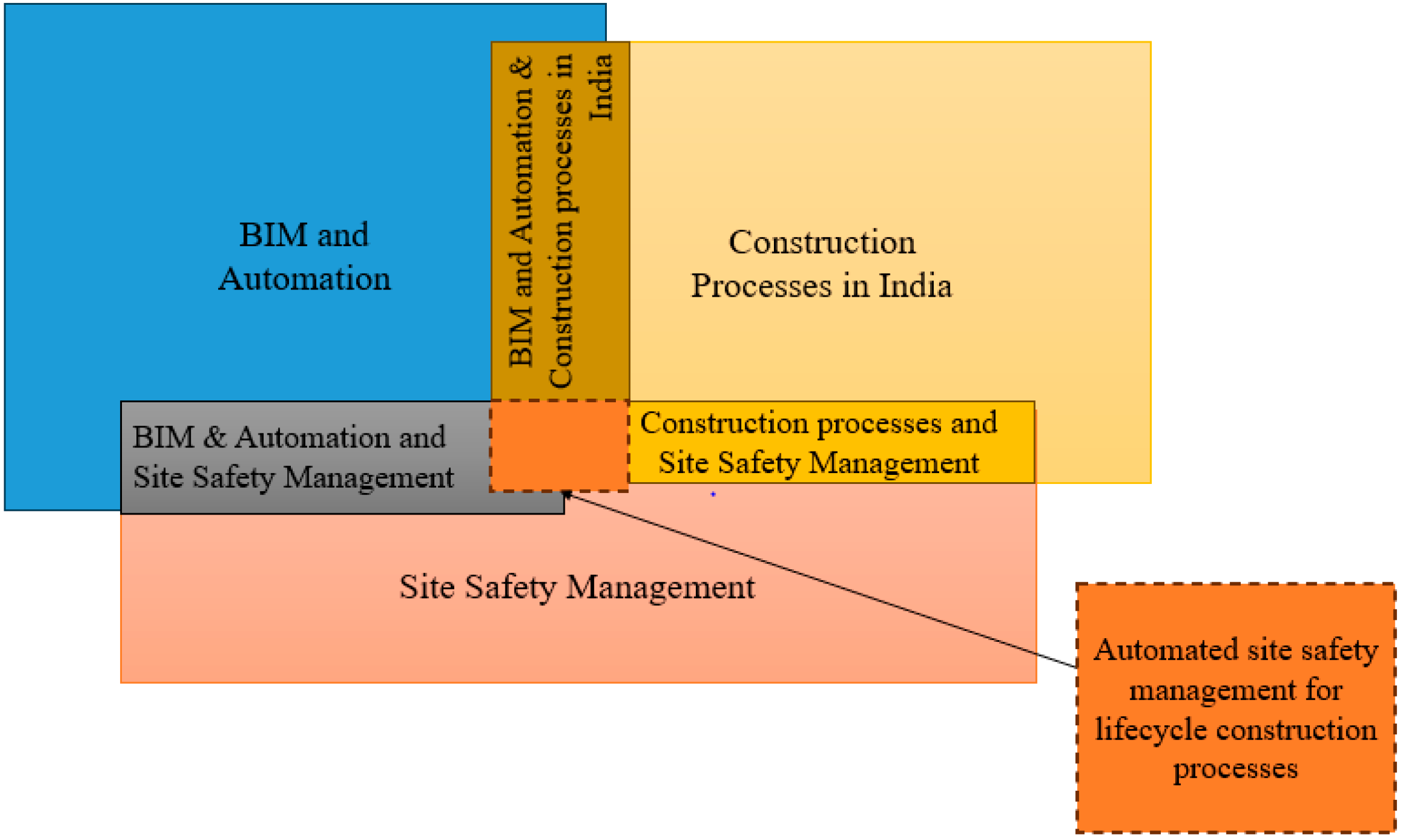
To identify opportunities for automated BIM-based site safety management, it is important to study and understand the existing site safety management processes. This research, although focused on site safety management practices in India, examines research from outside India. This helps us to understand advancements in site safety management practices globally and, as appropriate, apply lessons locally, i.e., within the Indian site safety management context. To understand the current processes, this research examined the current literature (topics covered in Figure 1) and includes findings from discussions with site safety experts. The key topics examined in this research are illustrated in the Venn diagram (Figure 1).
This study examines how BIM capabilities could be leveraged for effective site safety management. To understand this further, a critical review has been conducted and classified using three BIM approaches: (1) through 3D modeling with visual checks; (2) through automatic safety checks with rule-checking platforms; and (3) through integration with innovative technologies. To facilitate the BIM-based safety process, BIM tools play a critical role. Different tools can be used throughout the lifecycle of the project, so a complete safety solution set is provided. The tools identified from the literature review have been categorized as per their ability to fulfil the specific site safety objectives.
3.1. Conventional Site Safety Practices in India
This study began with a critical review of conventional safety approaches that are adopted on typical construction sites. Site safety is one of the major factors that affects overall construction productivity [16,17]. There are various ways in which safety management is explained. According to [18], the duties of setting the context, identifying, evaluating, assessing, treating, monitoring, and communicating risks require the systematic application of management policies, processes, and procedures. As per [19], the key process of typical conventional site safety management is risk establishment for the environment, hazard identification, risk analysis, risk evaluation, and risk treatment. Procedures for risk management involve continuous monitoring with routine evaluations of the safety results, and continuous improvement of the safety management system’s effectiveness [20].
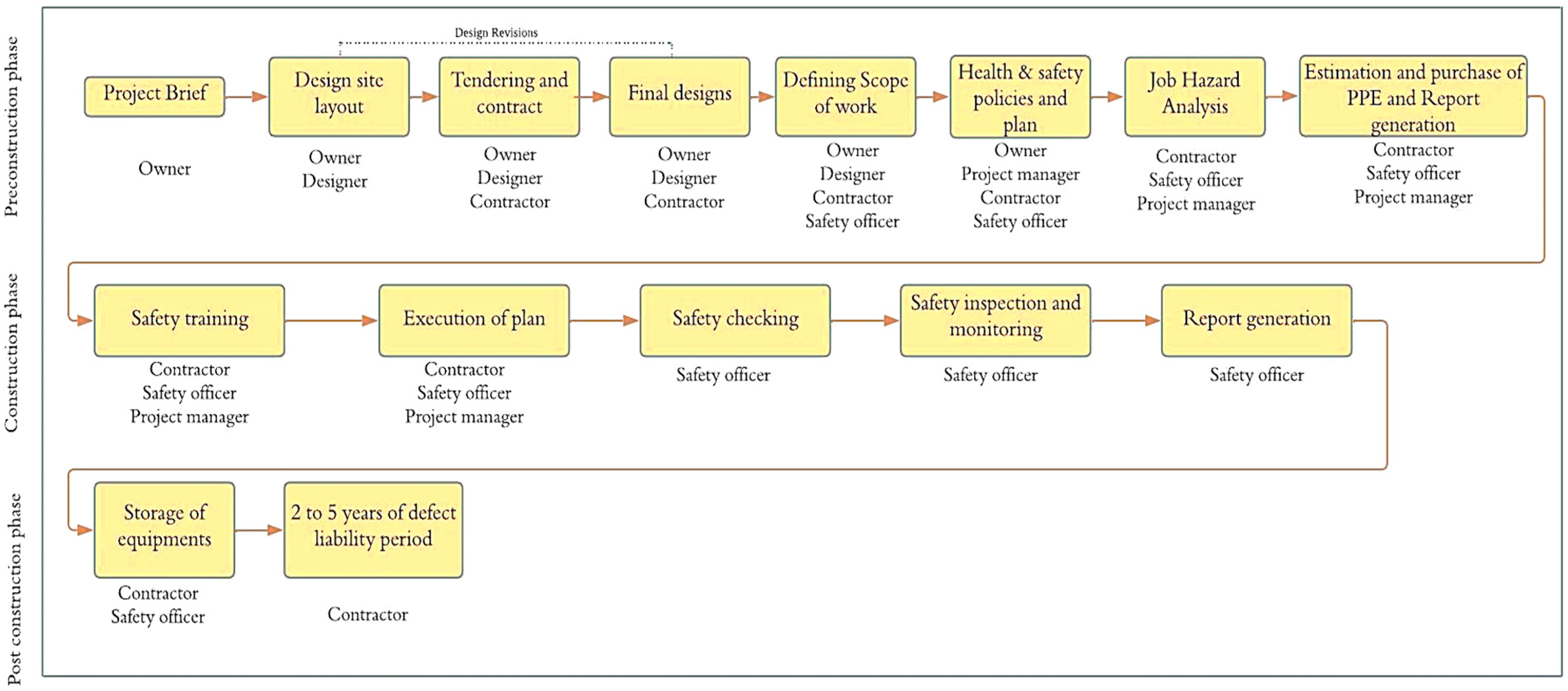
It is also important to understand the flow of these safety-related processes, the stage at which they are conducted, and the people who are involved in this process during the lifecycle of the construction project. On a typical construction project, the execution of work is mainly carried out in three different stages consisting of preconstruction, construction, and post-construction [21]. The preconstruction stage mainly includes the project brief, defining the client/user’s requirements and objectives in sufficient detail to enable the proposed facility to be designed and specified [22]. Designing is the most important step in any construction project. Based on designs, the contracts and tendering are invited for procurement. Various contractors submit their tenders. Considering the safety procurement, for large-scale projects following good safety measures, a separate safety department is appointed, but in the case for small-scale projects, safety is taken up by local contractors [23]. At the design stage, the factor of safety is considered by the designers. The factor of safety is the load-carrying capacity of a structural system beyond what it supports. Thus, the safety consideration in conventional design pertains to structural safety, as opposed to the practice of site safety management. Designers are not asked to consider worker safety [23], and, in the current safety practice, designers are held responsible for the safety of end-users while construction worker safety is the contractors’ responsibility [24]. After the finalization of the project by contractors, the planning department, along with the safety officer/inspector, defines the scope of work and finalizes the activities and their estimated times. The individual plan for each construction activity, i.e., excavation, slab-laying, etc., is designed as per the scope. Further, as per the scope, a health and safety plan is designed, which involves a Job Hazard Analysis (JHA) as a key tool to identify how to perform a step-by-step appraisal of the “job tasks and early identification of any hazards associated with the task, so controls to mitigate the hazards can be introduced”. This critical step, with its emphasis on job task analysis, ensures the early identification of hazards before they result in injury. Hazards are difficult to predict because even though the activities performed are similar or even the same, every construction project has its unique location, time schedule, and work conditions [25]. Moreover, construction sites are dynamic, and even if the hazards were accurately predicted for such precisely defined conditions, there is a large probability that the conditions could change by the time the construction activity is scheduled to be performed. The next step after identifying hazards and before deciding on mitigation strategies is determining the risk levels of the hazards. The risk level is most often determined by multiplying probability and severity scores. Quantifying severity, on the other hand, is much more abstract and is dependent on the safety expert’s judgment [25]. Further, as per the requirements made in the JHA plan, the safety equipment is estimated and purchased for execution.
Until the preconstruction stage, the safety process is paper-based. During the construction stage, the plan is implemented. The workers are given safety training as per the work schedule. The plan implementation and safety checking are supervised physically by a safety inspector. However, there is no evidence as to how strictly the plan is followed; a lack of adherence to standards is one of the major reasons for accidents at this stage. The thoroughness of the inspection held on-site varies from inspector to inspector. Site safety inspectors supervise construction sites based on their previous work experience and through visual observations and the identification of hazards. Hence, the hazards are identified during the construction stage. Typically, verbal instructions are given to mitigate any potential risk. The communication channels are often ad hoc and one-to-one, leading to a risk of costly mistakes because of miscommunication. A lack of communication among the various departments involved and a lack of proper inspections are the major reasons for accidents occurring at construction sites [23]. There is no evidence of the use of a common platform to share information between project stakeholders. Thus, the risk of defects and liabilities because of miscommunication is compounded. The site engineers employed by the contractor collect the necessary on-site progress data, and the progress of site work is recorded manually by updating the construction schedule, which is backed up by images, updates in the site diary, progress meeting minutes, and correspondence [26].
Record keeping of hazards is in the form of safety manuals and paper-based documents [13]. Based on the literature, a flow chart involving the different safety activities that take place in the project’s lifecycle has been prepared. The reported findings on conventional safety management in construction projects in India are presented in Figure 2. All components of the current safety approach illustrated in Figure 2 take place in the physical environment.
On a typical construction project in India, to some extent, safety during a construction project is influenced by decisions made at the early planning and design stages. Thus, the early identification of risks and hazards would ensure that mitigating measures are introduced early on, and safety on site is enhanced. In the early design stage, designs are in a state of constant flux, undergoing changes. Thus, a fluidity in the program is observed. Time and cost estimates are based on the design. So, if the design is ambiguous, then all subsequent activities would be affected, which in turn results in time and cost overruns.
There are several problems with current hazard identification in the construction industry. In India, on a typical construction project, most of the safety management processes are largely paper-based. Manual observations, which require a lot of work and are prone to error, are used to carry out safety planning. There is a lack of practices that identify the risk-prone areas before commencing with construction [13]. There are no specific digital tools that are used on construction sites for safety. AutoCAD is used for designing, but the rest of the processes are carried out by referring to printouts of drawings (e.g., plans, elevations, and sections, to name a few). Traditional safety planning relies on manual efforts for identifying and preventing safety hazards [27]. This approach is manual and based on the knowledge and experience of the safety planner; the process is labour intensive, time-consuming, inefficient, and error-prone [27,28].
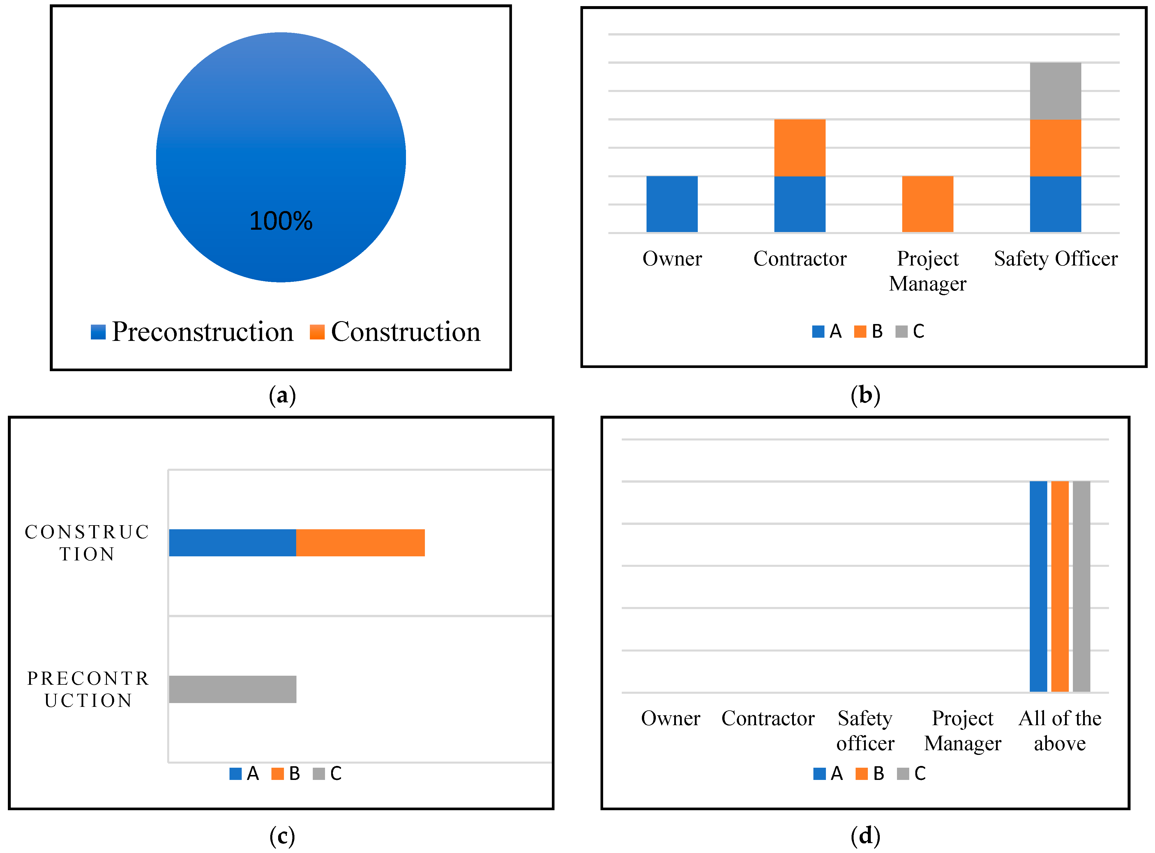
To obtain a more realistic view and the current state of the safety practices in Indian AECO, the flow diagram was critiqued by industry professionals through a small semi-structured interview. For this study, three semi-structured interviews were conducted in June 2022 with representatives of various construction companies. The sampling technique adopted for this survey was judgmental sampling and it is often referred to as selective or subjective sampling, which relies on the researcher’s discretion when determining who to ask to participate. The targeted interviewees had rich experience in working on construction projects. Two interviewees were employed as health and safety officers with 15 and 9 years of experience and one interviewee was an owner and contractor with 12 years of experience in the Indian construction sector. Currently, they are associated with multinational companies and contracting firms. The early career professionals understood the current technology being used in construction sector; the mid-stage career professionals were aware of current construction processes. The interview combined open-ended and closed questions. Figure 3 represents the analysis of closed-ended questions and their responses.
The analysis was conducted using MS Excel (Version 2312) where A, B, and C indicate the responses received from three interviewees.
The process for analyzing and interpreting these three interviews involves reviewing the data that were collected in the form of detailed notes. In the respondents’ opinion, the first step for site safety management is understanding the needs; the safety measures required and safety planning, including ensuring that all safety equipment are procured as per the plan. The key steps of safety management that are followed before the commencement of construction include the preparation of the safety plan, hazard probability and severity analysis, the arrangement of PPE, documentation, and safety training for workers. On the commencement of construction, the safety plan is implemented, and the safety inspector supervises the site. Sometimes a site person in charge also supervises the site, conducting toolbox meetings. The recording of hazards is manual, and reports are maintained of daily safety activities. For unforeseen hazards, an emergency plan is prepared, and the opinion of a safety expert is considered during decision making. At the design stage, structural safety is considered, and different design codes are followed; however, designers are not asked to consider the safety of workers.
The responses from the interviewees mapped with the flow chart of conventional safety processes. Their responses helped to strengthen the flow chart (Figure 2). From the interviews it was also noted that, at the design stage, designers consider the codes, which are mainly for structural safety. The supervision is manual, and decisions are based on the expertise of an officer.
The growing rate of accidents [29] points to the severity of the problem and is a strong indicator that conventional approaches are simply not effective. It points to the need to adopt a fresh and improved perspective that promotes effective safety management practices. This research leverages the capability of advanced technologies and promotes safer practices on site.
3.2. BIM for Site Safety Management
The global construction industry has been rapidly moving towards digitization. The adoption of computerized tools to support lifecycle construction processes has rapidly increased. BIM is an enabler of digital information and has gained prominence in the industry and academic research. Different countries are at different levels of maturity. A bibliometric analysis carried out by [5] examined global BIM trends that point to the varying levels of BIM maturity across the globe, and more specifically to the emerging presence of BIM in the Indian construction industry. Thus, the urgent need to act is more pronounced than ever before.
BIM is an integrated process which helps complete a project faster and for less money while reducing risks related to the environment, workplace safety, and other issues [30]. With the help of various BIM-based tools and techniques, safety planning can be carried out more effectively than with a conventional approach. This section explains the BIM approaches and associated tools for the management of construction site safety. There are three different approaches through which risks can be identified in a BIM environment.
3.2.1. Through 3D Modeling with Visual Checks
Modeling is the basic requirement for any digital construction management process. 3D BIM is the process of creating geometrical and non-geometrical information and sharing this information in a common data environment (CDE) [31]. Through this simulation the location of risk areas, the required safety measures, the scheduling of safety plans, and the identification and estimation of PPE can be performed. Three-dimensional models help users to visualize the project well in advance before the structure is constructed. Safety officers can examine the virtual model through a rendering and provide their inputs. Once the model is corrected, it can be used for the final construction stage. This model can be used to train workers to virtually identify hazardous areas and take safety measures accordingly [32]. There are a variety of BIM tools that are used for modeling purposes, for instance, Autodesk Revit, Tekla [33], and SketchUP [34], to name a few. The most popular BIM modeling tool used by Indian AEC professionals is Revit [13]. It is one of the most popular software packages in Autodesk [35,36]. These platforms can be combined with other tools using the export/import function. For example, a Revit model can be exported to Navisworks, which then extends its capability to identify the clashes in the project, and offers 4D scheduling capabilities [37].
The Revit is 3D modeling tool and does not have an ASC capability within. It relies on human input to visually verify whether the model meets the health and safety requirements. Thus, the accuracy of the check is dependent on the knowledge and expertise of the human.
3.2.2. Through Automatic Safety Checks with Rule-Checking Platforms
To determine the requirements for safety equipment on a construction site, traditional safety planning still mostly uses paper-based 2D designs and schedules [28,38]. It also has a problem with the separation of the design and implementation phases. Traditional approaches rely on safety inspections to identify potential dangers and annotate pertinent 2D drawings [39]. Currently, the creation of new tools and technology encourages designers to take construction safety into account early in the design process. Thus, the requirement for safety planning during the design process is becoming more and more apparent. Past studies on information technology-enabled methods or tools for PtD focused on clash detection [40], knowledge-based systems, and rule-based systems. The degree of automation and efficiency in PtD has been improved to a certain extent. However, most existing studies are partial and fragmented or still at the concept and prototype stage [41]. Additionally, effective safety planning is essential for reducing delays and overhead costs [28].
Safety standards (e.g., OSHA) play a crucial part in the safety management of a project as they contain the basic guidelines used to assess hazards. The safety standards are most often paper-based guidelines and procedures that must be followed when carrying out building work and the requirements for specific aspects of a construction project. Rule checking aims to automate the paper-based safety rules and check the design of a project to identify its hazards. To automate the safety rules, they need to be converted into a machine-readable format. ASC is not a function supported within existing BIM-based software. It can be achieved by either incorporating a plugin into the software (for example Revit, ArchiCAD, or Tekla) or by integrating the BIM platform with a rule-checking platform or, alternatively, within a platform that can read building models (for example, IFC (Industry Foundation Class) platforms and Navisworks) [33]. There are benefits and drawbacks to every integration technique (tool type). Since it would be integrated natively into an already-existing software program, like some commercial BIM authoring tools, the plug-in might be the easiest to install. A few programs already have integrated programming tools, like the Application Programming Interface, built-in (API). The major downside in this case would be the limitation to only one BIM authoring software. Due to possible issues with data interoperability, only native BIM models could be used by the system. Another potential issue is the limit of the programming capabilities of the integrated programming tool [25].
To codify the safety rules, various rule-checking systems such as ePlanCheck, FORNAX [42], Sematic Web [43], Kbim [44], and Natural Language Processing (NLP) [45] are available. The Solibri Model Checker is a commercial program that is widely used in various nations, [46]. The Solibri Model Checker has now been superseded by Solibri Office, which can import models from all major BIM software products and allows users to interpret the safety rules and identify hazards from the model. The benefit of these systems is that they check the model in a virtual environment and identify the hazards at the design stage itself. Some widely used rule-checking platforms and their code representations are presented in Table 1 below.
The most important step in automated code compliance checking is the rule interpretation process, for which a number of technologies have been researched and used. There is no standardized way for converting the rules and regulations into a computer-readable form [50]. The above-mentioned platforms have some limitations associated with them. For instance, the FORNAX is a computable rule that will then work with the FORNAX library, but not on any other platform. Similar is the case of SmartCODES; the greatest challenge is its applicability to various kinds of text from different rule sources [51]. Solibri is the only commercial software available for checking some aspects of building design like clash detection and space validation [50]. Through the use of the IFC schema and a separate software package, it is possible to import models from almost any BIM modeling tool, making it less constrained by the capabilities of the programming language being used. Additionally, the software itself could incorporate a few basic modeling features.
3.2.3. Through an Integrated Approach
In the construction sector, technology has been crucial in identifying site risks. The availability of technology is thought to make construction safety attainable. There are various technologies that have been integrated with BIM. BIM aims to provide real-time hazard identification, accident prediction, workspace planning, and more. The BIM can be integrated with other technologies, which mainly include the Global Information System (GIS) [52], UAV [53], Global Positioning System (GPS) [54], Radio Frequency Identification (RFID) [55], Ultra-Wide Bands (UWBs) [56], and sensors [57]. The application of all these technologies is presented in Table 2.
Monitoring and control systems are used to make sure that safety regulations and standards are followed when implementing safety measures during a project. Data from real-time data capturing technologies (e.g., UAVs such as drones) can help to monitor progress on construction projects. Drones have a fantastic potential to increase construction site safety [61]. The use of 4D simulation and scheduling in BIM-based modeling has greatly improved safety and logistics applications.
Many research articles contain more than one technology or approach. It was discovered that BIM and 3D/4D models have a boundless potential to integrate with technologies used in construction site health and safety [62]. However, only a small amount of automation in safety process modeling and planning has been utilized thus far [63]. These technologies are advanced in comparison to conventional practices. However, there are some limitations associated with these technologies. For instance, in the case of UWBs, they do not produce a strong signal, and were unable to pass through more than two heavy walls. A single UWB receiver also does not cover a large area effectively. So, with its capacity it could alert the workers regarding hazards within a limited area. The positioning sensors required a high-frequency strong sensor, and this had given false alarms sometimes. For GPS-based safety tracking, continuous Wi-Fi is required, and this system is very expensive.
Although three different BIM approaches are reviewed (Section 3) in this paper, this paper focuses on approach 2, which is an automatic safety checking (ASC) approach. The purpose behind selecting this approach is because it considers hazard management holistically at the design stage, which covers hazard identification, safety checking, corrective actions, and reporting. The first approach, that of 3D modeling, is limited to risk identification, and it relies on humans for checking. However, the third approach is about real-time safety, which relies on hazard-capturing tools. If safety is effectively managed at the design stage, then it certainly helps to minimize real-time hazards as they have already been considered. Hence, the scope of this study is focused on reducing the risks at the design stage, offering the lifecycle management of hazards in the virtual environment. This study proposes a conceptual framework for BIM-based ASC and incorporates some of the identified BIM tools to provide an effective safety solution that is hazard-free. Since it can be difficult to identify which tool can be used for fulfilling different safety objectives, a categorization of tools was necessary. This helped us to identify which specific tools are used for specific safety requirements at different periods across the entire ASC process.
The above review explained the different BIM approaches for safety management throughout the lifecycle of a project. In addition, it was observed that most of these technologies focused on one type of hazards, i.e., fall hazards; there are various types of fall hazards such as unprotected edges, holes and openings, staircase falls, and scaffolding falls. Each of these causes needs to be considered while designing the technology-based safety system. It is also noted that the majority of these technologies were created with safety solutions for the construction stage in mind. Nevertheless, it is necessary to expand the applications of technology for construction safety beyond the construction stage to include the preconstruction and post-construction phases. The majority of these technological applications were restricted to academic research and had limited implementation for construction safety management. The focus should be more on transitioning technology from research into practice.
To facilitate BIM-based safety processes, BIM tools play a critical role. For the purposes of this research, BIM tools are software (e.g., Revit, Navisworks) that support the BIM process. Here the software could be one proprietary tool or a suite of a few. Different tools can be used throughout the lifecycle of a project, so a complete safety solution set is provided. The tools required at each stage may not be the same. Hence, to identify the tools according to their use, as well as the stage at which they can be used, a categorization of these tools is carried out and presented in the next section.
4. BIM-Based Tools for Safety Management
Based on the review conducted, the different tools have been identified. These tools have specific functionalities that can be utilized as per the safety requirement throughout the lifecycle of the project. Table 3 shows the project stage-wise requirements of BIM-based safety processes and suitable tools that can fulfill those requirements.
The safety requirements and their tools mentioned above show that, at each stage of construction, different BIM approaches can be adopted. At the preconstruction stage BIM helps to build an as-planned model, while at the construction stage it builds an as-built model, and at the post-construction stage it creates an as-constructed model. The as-planned model differs substantially from the as-built model for reasons including rework and other changes to the original design made as construction progresses. All these models are generated at different stages, with a huge amount of information forming a repository of the data of the entire project. The potential of BIM-based safety is that it allows designers to combine different platforms with distinct natures.
The identification and categorization of tools helps us to understand which BIM tools could be used to perform a specific safety requirement. There are different safety requirements throughout the lifecycle of a project. For instance, in a typical safety management scenario of a construction project, the requirement of 3D modeling can be carried out using the tool Revit, likewise the scheduling requirement of safety activities can be fulfilled using Navisworks. The ability of a single tool is limited and alone it cannot meet different safety requirements. However, with the interoperability of BIM different tools can be combined, and a complete package of safety solutions can be achieved.
The categorization of tools helps us to develop a conceptual framework by indicating the specific tools needed for specific safety requirements at different periods in the entire ASC process, with the aim of the early identification of hazards. The identified tools also help us to understand the nature of the input data required for conducting the process in the respective tool. The type of tool determines the data input requirements to be ‘processed’ to produce a hazard-free site safety output. This forms the basis of the conceptual framework presented in this paper.
The novelty of this study is the proposed framework for the early identification of hazards by safety checking with standard rules at the preconstruction stage. It also includes the virtual scheduling (4D) of required safety equipment, which is typically carried out at the physical construction stage, followed by information storage. All of these steps are the lifecycle of risk, which is typically managed in all three stages of construction (lifecycle stages). However, this study proposes a framework wherein all these steps are managed at the preconstruction stage itself, in a virtual environment. Hazard identification, and its virtual inspection, will be conducted in a virtual environment prior to actual construction. Further, the framework is validated for the one-hazard case of an Indian construction environment, highlighting the potential benefits of BIM-based automatic site safety checking that can support current safety practices for the effective site safety management of construction projects.
5. Development of BIM-Based Automatic Safety Checking Framework
Considering all BIM approaches, and to understand the process flow of ASC, this study presents a conceptual framework. This framework is developed for the lifecycle management of a Hazard Scenario (HS) in virtual environments, with the main purpose of reducing the onsite hazards by managing them at an early stage of construction. The designs are the critical element of the entire construction project, as further execution of the project is dependent upon the designs, and so also the designers. If the safety management can be achieved through the design, major delays, reworks, and overruns can be avoided at an early stage. Hazard identification achieved at an early stage can save the time required for physical identification. In addition, design errors such as conflicts in the design, the overlapping of structural, mechanical, plumbing, and electrical elements, leads to a rework of the design, through which the project schedule is impacted [64]. These clashes can be detected and fixed before the construction begins, and reduce the rework required as well the associated delays [65]. The study of conventional safety practices helped to identify the key processes that must be considered while developing any safety management framework. Those processes include risk identification, safety checking with standards, and safety monitoring and reporting. These identified processes form the basis for the development of an ASC framework, and they are performed in the Preconstruction, Construction, and Post construction stages.
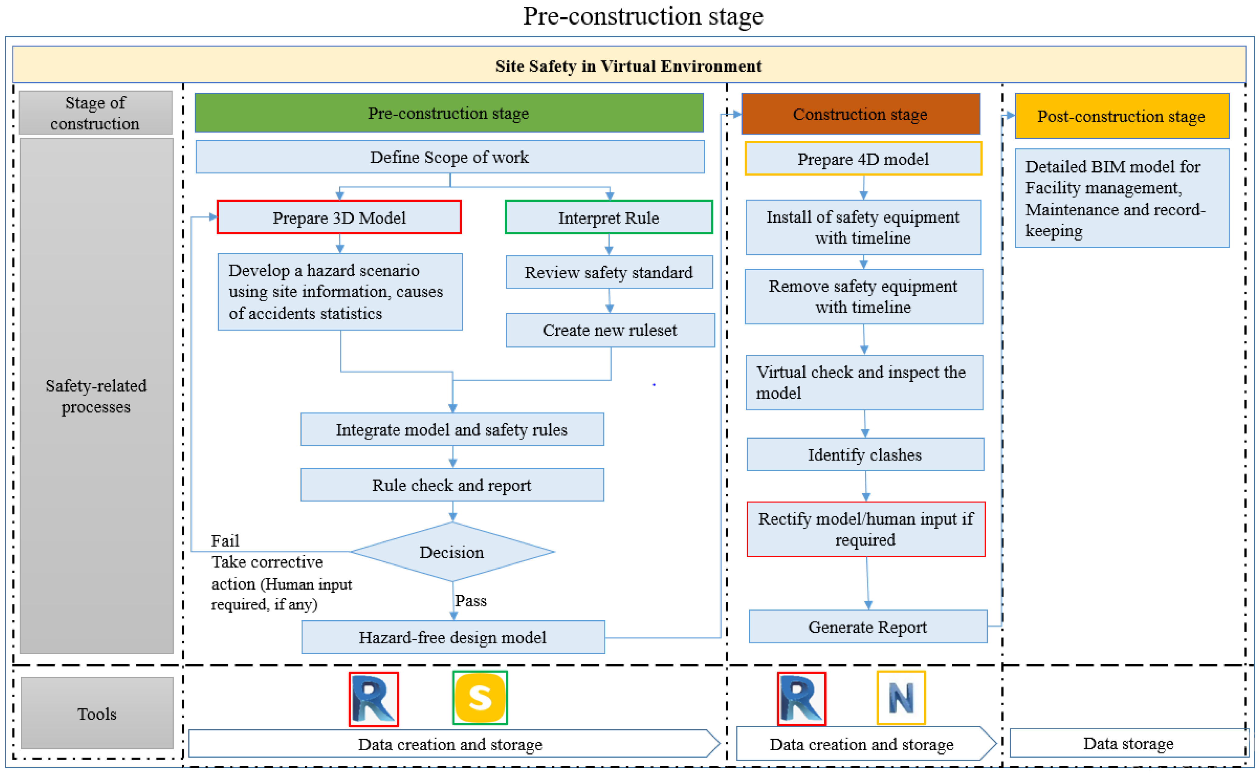
To perform the key processes in ASC, some steps have been designed. The key steps in the framework include the preparation of a 3D model, interpretation of safety rules, integration of the model and the rules, rule checking and reporting, and preparation of a 4D model followed by report generation. The process of ASC is continuous until the design is hazard-free, with all safety checks passed. The output for this process results in the hazard-proof design of the construction project along with safety provisions and its schedule. Figure 4 depicts the conceptual framework for ASC to be conducted at the preconstruction stage in a virtual environment.
The process of ASC begins at the preconstruction stage. The key steps designed to be conducted in this stage are explained below:
- Define scope of the work: There are multiple sequential activities (excavation, foundation, slab casting) to be conducted in an entire construction project. Each of these activities requires specific safety measures. Hence, to manage these measures effectively, the framework begins with defining the scope of the work. In this study, the scope of the work includes considering hazards and designing the HS. To design the HS, past research on types of accidents and hazard statistics from various organizations can be refered to. For instance, in the activity of slab casting (a scope), one major hazard that led to falls is the “Unprotected edges of slab”. So, complete ASC will be performed for this HS in a virtual environment. Similarly, different HSs can be considered, and safety checks can be performed.
- Prepare 3D model: This is a fundamental step of ASC. In this process, 3D models provide highly detailed geometric and parametric information about the construction components. The facilitate this, the input data required are drawing plans (2D plans) along with all sets of dimensions, such that the HSs can be presented in a 3D model. One of the key benefits of BIM-enabled ASC is the virtual replica of the developed construction project, which helps designers to observe and identify issues in a cyber environment. The proposed framework uses Revit (Version 2020) as it is one of the most popular 3D modeling tools.
- Interpret safety rules: A vital step of the ASC process is converting the paper-based safety rules into a computer-readable format. This interpretation requires data on the standard safety rules (OSHA). Notably, these rules are in sentence format and need to be converted into a parametric format. For this purpose, Solibri office (Version 9.13.0.23) is used as it is recognized as a prominent tool for rule checking and interpretation. For instance, as per OSHA [66], the standard rule for an unprotected edges scenario is that “Each employee on a walking/working surface (horizontal and vertical surface) with an unprotected side or edge which is 6 feet (1.8 m) or more above a lower level shall be protected from falling by the use of guardrail systems, safety net systems, or personal fall arrest systems”. This textual rule is considered while interpreting and converting it into a parametric format along with the dimensions of the guardrails.
- Integrate the model and safety rules: Once the rules are interpreted, they need to be assimilated with the information-rich 3D model. The interoperability function of BIM allows us to exchange data between two different platforms. Here, the 3D model is integrated with a rule platform using an IFC capability. During the integration, the rule-checking platform reads the 3D model and makes it ready for performing rule checking.
- Rule check and report: The successfully integrated model can be checked for designed HSs with associated safety rules from Solibri. The checking would result in a passing or failure of the rule. If the rule is passes, it indicates that the model design is hazard-free. However, if the rule fails, it shows that the design has errors and does not comply with the safety rule. A detailed report and presentation of hazards can be created, along with responsibilities to be assigned, in platform itself. The report for hazards includes detailed information about hazards such as the components of the hazard, its location, and mitigations. The report can be sent to the design team to make the corrections.
- Take corrective action and recheck: This step involves the redesigning of the 3D model considering the hazard measures mentioned in the report. The 3D model needs to be updated and rectified. Further, safety checking can be performed until the rule is successfully passed and the model becomes hazard-free.
Once the checking of all scenarios is completed, the hazard-free design can be progressed to construction stage, which includes scheduling. The steps designed for the construction stage are explained below:
- 7.
- Prepare 4D Model: The hazard-free model is further progressed to scheduling. The scheduling of construction activities helps us to understand the sequence and time required for each activity involved. The 4D BIM deals with the time function. The schedule of the project is required as input data here. In this step, safety activities such as the installation and removal of safety equipment such as guardrails is scheduled with the tool Navisworks (Version 2020). The 4D model will ensure the correct sequence of the guardrails, i.e., if the walls or any vertical element across the edges of slabs are to be constructed the provided guardrails will be removed, and the same guardrails will be reinstalled for the next slab. This way, the model will use the required set of guardrails repeatedly throughout the construction work to maintain economic viability.
- 8.
- Inspect virtually and monitor: In this step, the safety officers and project managers can inspect the model virtually. This will provide a clear understanding of the sequence of safety activities, while clashes can be resolved, and any required modifications to the schedule or design can be carried out before the model proceeds further.
- 9.
- Generate report: the final report of the ASC for the project includes a hazard-free 3D design model, the location and properties of PPE, a schedule for installation and the removal of PPE, and details of the data generated throughout the process.
At the end, in the post-construction stage, the data which are created throughout the process are stored and used for facility management purposes. These data can be used for future projects/renovation of the building, and maintenance purposes [67]. The data generated through the safety checking process can be used for similar kinds of projects to locate hazard cases, their mitigation, and equipment information, eliminating the repetition of all the safety checking steps.
The output for this ASC process is a hazard-free construction design at the preconstruction stage. All the safety measures are provided in the virtual environment, including the project’s scheduling and data storage. The mitigation measures are proactive rather than reactive.
6. Validation of the Framework
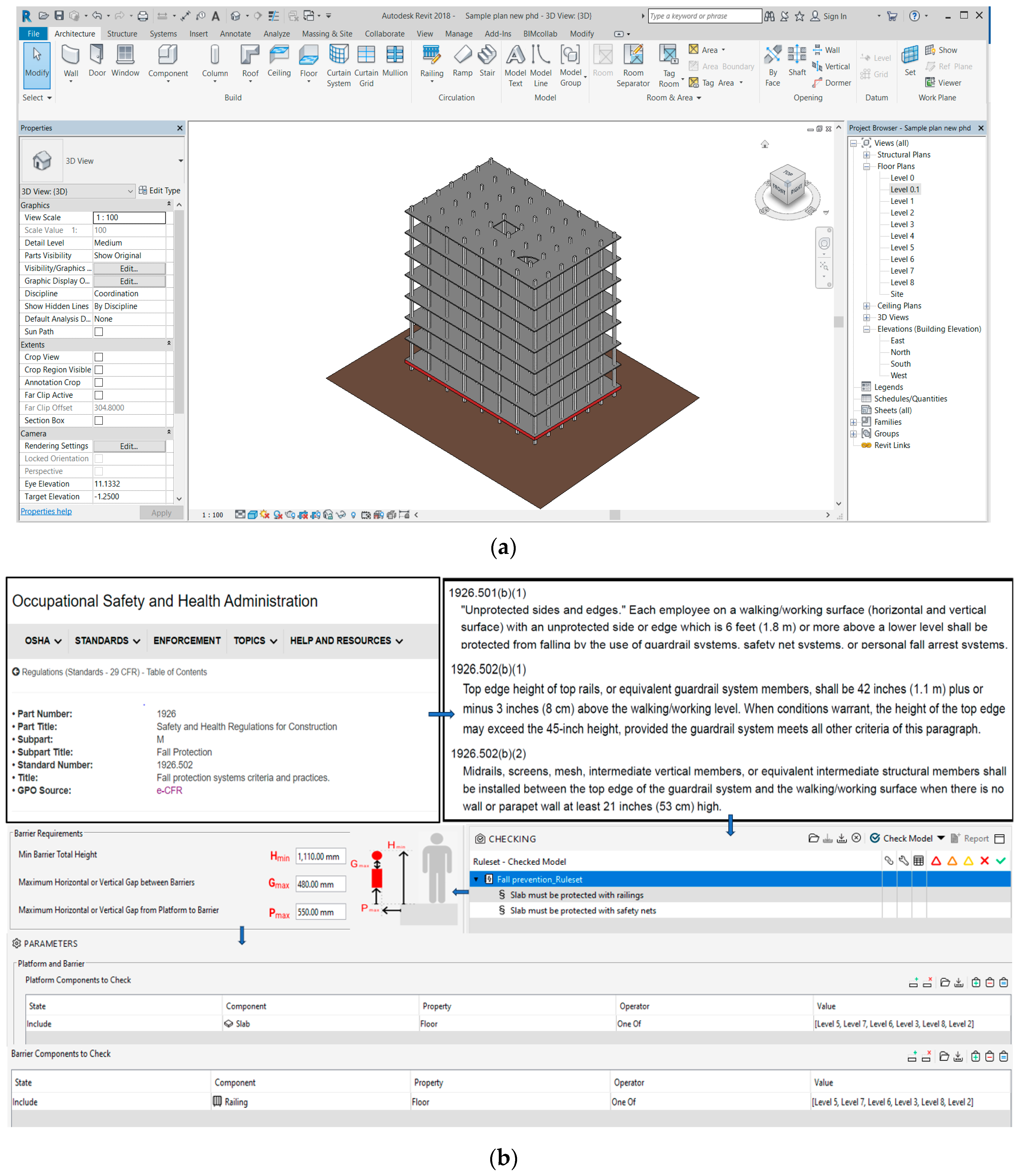
For the validation of the proposed framework, a pilot study is conducted with the one-hazard scenario of the unprotected edges of a slab. A sample 3D model without a safety guardrail system at the edge of the slab is created using Autodesk Revit. To perform the automatic safety checking, all the required steps presented in the framework are followed. In this study, the framework is validated for the preconstruction stage, which mainly consists of the automatic safety checking of the model for a hazard-free design. Figure 5 represents the validation results for the sample model.
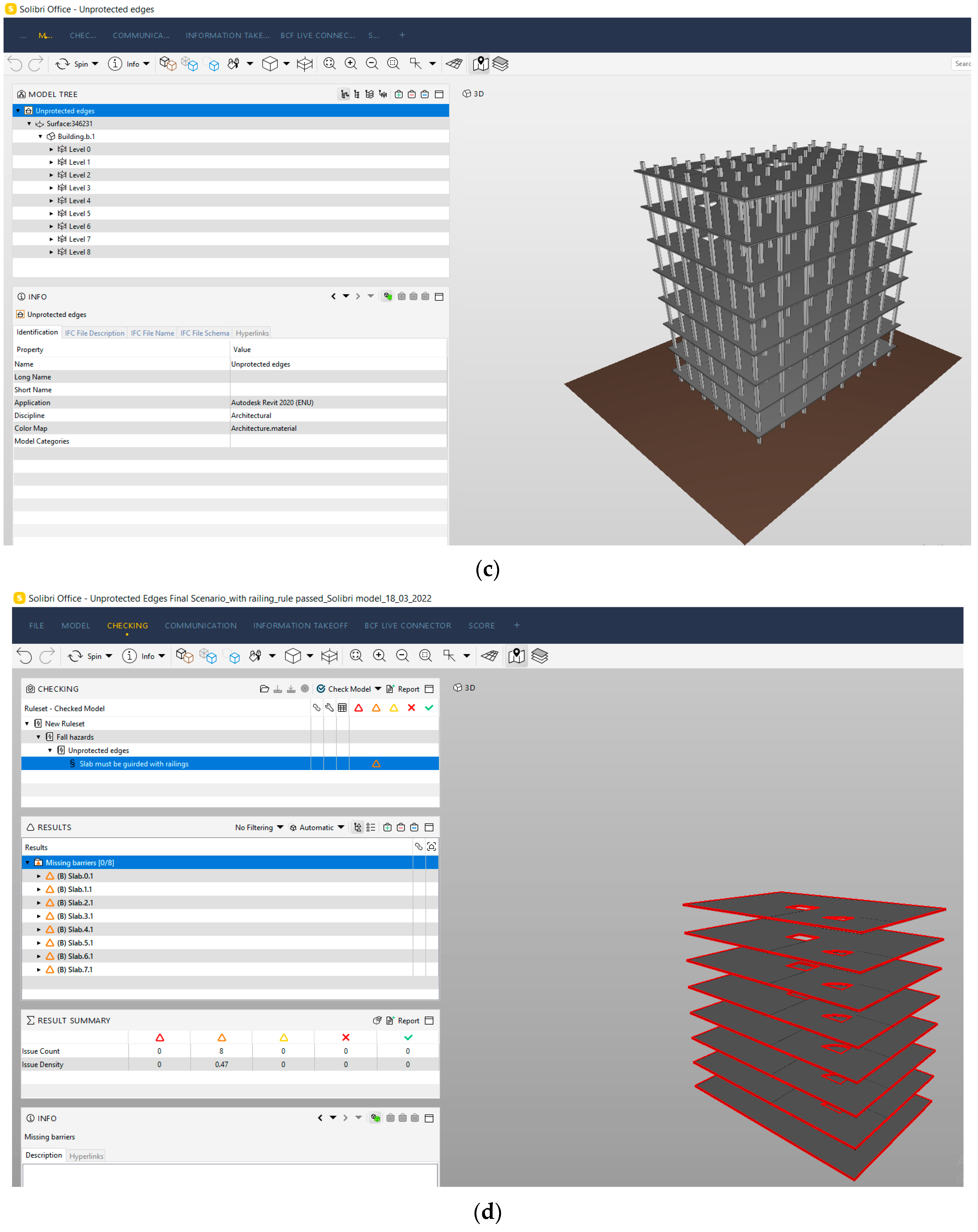
The safety rule for the case of an unprotected edge of a slab is identified from OSHA. In Solibri Office, using the ruleset manager, the rule is created as “Slab must be protected with guardrails” and all the required dimensions of the guardrails are converted into a parametric table. Further, for the purpose of integration, the 3D model is converted to IFC and transferred to Solibri Office (Figure 5c). Furthermore, the rule checking is performed in Solibri, and it runs successfully. The hazards are identified and represented by missing barriers along the edge of the slab, highlighted with a red-colored line (Figure 5d).
Once the hazards are identified, the reports will be generated (Figure 5e). The report highlights the edges of the slabs which are unprotected, and it also mentions that there are missing barriers for the slab levels. So, here it is identified that the design is not hazard-proof and needs revision. The generated report of the identified hazards will be communicated for corrective actions. Figure 5f represents the corrective actions taken in the form of the provision of safety guardrails to the 3D model.
After the corrective actions, the model is integrated with the rule-checking platform once again, and a rechecking of the model is performed. The checking is performed until all the slabs are provided with guardrails of an appropriate size and the design is hazard-free.
After a successful passing of the rules, a hazard-free 3D model is obtained, and a report is generated. The next part of the framework includes the 4D model, and this will be performed in future work, where the scheduling of safety guardrails will also be performed.
7. Discussion
The BIM-based automatic safety checking system has different benefits for safety management. Some of the benefits are discussed in this section.
- 3D modeling and the visualization of hazards: As opposed to updating a 2D design, a 3D model enables designers to explore a wider range of options during the design process and adjust the design quickly and effectively. The benefits of the 3D model are not limited to visualization, as it also offers precise geometrical and parametric information about the construction components. Hazard areas can be visualized in the model and required preventions can be checked out. The visual model can be used for providing safety training to the workers. The 3D model is an excellent communication tool for all stakeholders. Safety officers can virtually review the project and can provide their inputs to reduce the possible risks earlier.
- Eliminates relying on manual checking: The process of ASC in the proposed framework mainly relies on computerized safety rules. The paper-based rules are interpreted and stored in a library of the rule-checking platform. These rules automatically check the model, identify the hazards, and provide safety solutions. Unlike conventional approaches, it does not have to rely on human decisions. However, it also allows humans to provide their input if required.
- Guaranteed to follow safety guidelines: Obedience of the safety standards is crucially important in any construction project. The ASC completely relies on the standard rules that are codified. The design model can go through standard-based safety checking at the design stage.
- Scheduling of safety activities: The technique of intelligently connecting a 3D digital model with time- or schedule-related information is known as 4D BIM. Navisworks can be used to plan PPE installation and removal procedures while taking safety into consideration. This has eliminated the problem of misunderstanding brought on by a lack of visibility that was present in conventional construction scheduling.
- Storage of information: Data management in construction is equally important in as huge volumes of data are generated over the entire construction project. In the process of ASC, the rules will be interpreted and stored in a library which will form the knowledge database for different HSs. Because of the automatic systems, at each stage the data will be stored in the required format, which can be used anytime in the future.
8. Conclusions
The applications of BIM for site safety checking can provide effective safety solutions throughout the lifecycle of a project. However, its potential applications are not fully explored in India’s construction industry. Nevertheless, the need to better manage safety process lifecycles is clear. Poor safety practices lead to increases in accidents and reduced productivity. This study examined the current approach of conventional site safety practices and reveals different BIM-enabled approaches to site safety. The conventional approaches are paper-based and rely on human decisions. These practices are error-prone and reactive. In the conventional process, at the preconstruction stage, paper-based methods such as checklists and manuals are prepared; however, there are no methods that can identify the hazards prior to construction, and no adherence to safety standards is ensured. These safety practices hence lack the proper execution of safety activities, which leads to onsite accidents. This study provides direction to streamline the focus on overcoming these challenges with different BIM-based approaches. The major contributions of the present study to the existing body of knowledge are two-fold. First, the different BIM tools for lifecycle safety management are identified and categorized, as per safety requirements, in the form of a comprehensive table for construction professionals. This will help us in understanding the abilities of different tools and the input data required for fulfilling different safety objectives throughout the lifecycle of a project. The integration of BIM with innovative technologies such as UAV, GIS, GPS, and RFID can provide the best possible solution. Second, a conceptual framework for the early identification of hazards is developed.
The lifecycle management of a hazard is considered in the virtual environment. The proposed framework allows for the ASC of a construction project by integrating its 3D model with computerized standard safety rules. It also provides the scheduling of safety activities. This framework is validated with a sample model for hazard identification obtained by performing automatic safety checking.
Considering the growing rate of onsite accidents, the current practices need improvement and ASC can overcome the challenges of conventional approaches. This conceptual framework analyses how BIM can be used for site safety in the lifecycle of project management and provides a conceptual foundation to facilitate further research into the implementation of BIM in practice. The process of ASC requires information from different disciplines such as design, safety rules, and schedules, and here all these are integrated, which enhances their multidisciplinary collaboration. The stakeholders, along with the safety officer, will be involved, since this process occurs at the preconstruction stage and they can provide their input from the start, which will lead to the smooth performance of work at the construction stage. This ASC process would form a library of safety rules that can be used by construction professionals to check their designs and manage the hazards involved. Designs and their related hazards can be visualized in a 3D environment; hazards can be identified, and checking can be performed until the issues are solved or corrective actions are taken at the design stage itself. By identifying hazards earlier, the rework can be reduced, leading to reduced time and cost overruns. An early plan for the scheduling of safety activities helps stakeholders to consider all possible delays before the execution of work and keeps the project on track. Through virtual training, workers can be informed about hazard-prone areas and can prepare accordingly. Through the ASC process accidents can be minimized by considering them at the design stage. The knowledge which usually takes place at the construction stage is brought forward to the preconstruction stage.
In this study, the model was validated only up to the automatic safety checking stage for the early identification of hazards. The further part, 4D scheduling, will be validated in future work. Also, only a one-hazard scenario was considered for safety checking; future research can focus on implementing the framework for different types of hazard scenarios.
Author Contributions
Conceptualization, S.H. and K.R.; Methodology, S.H. and K.R.; Validation, S.H.; Writing—original draft, S.H.; Writing—review & editing, S.S. and K.R.; Supervision, S.S. and K.R. All authors have read and agreed to the published version of the manuscript.
Funding
This research received no external funding.
Data Availability Statement
Some or all data, models, or code that support the findings of this study are available from the corresponding author upon reasonable request.
Conflicts of Interest
The authors declare no conflict of interest.
References
- Musarat, M.A.; Hameed, N.; Altaf, M.; Alaloul, W.S.; Al Salaheen, M.; Alawag, A.M. Digital Transformation of the Construction Industry: A Review. In Proceedings of the 2021 International Conference on Decision Aid Sciences and Application 2021, DASA 2021, Sakheer, Bahrain, 7–8 December 2021; pp. 897–902. [Google Scholar] [CrossRef]
- Webb, T.; Langar, S. Utilizing BIM as a Tool for Managing Construction Site Safety: A Review of Literature ollege Students’ Perception of Household Energy Efficiency View Project Residential Industry Perception for Resilience View Project. 2019, pp. 339–347. Available online: http://www.ascpro.ascweb.org (accessed on 27 March 2023).
- Stewart, O. Semiotics: What It Means, and What It Means for You. Sablono. 2022, pp. 1–14. Available online: http://www.psychologytoday.com/blog/ambigamy/201102/semiotics-what-it-means-and-what-it-means-you%5Cnhttps://www.psychologytoday.com/blog/ambigamy/201102/semiotics-what-it-means-and-what-it-means-you (accessed on 24 December 2023).
- Gerrish, T.; Ruikar, K.; Cook, M.; Johnson, M.; Phillip, M.; Lowry, C. BIM application to building energy performance visualisation and managementChallenges and potential. Energy Build. 2017, 144, 218–228. [Google Scholar] [CrossRef]
- Hire, S.; Sandbhor, S.; Ruikar, K. Bibliometric Survey for Adoption of Building Information Modeling (BIM) in Construction Industry—A Safety Perspective. Arch. Comput. Methods Eng. 2021, 29, 679–693. [Google Scholar] [CrossRef]
- Eastman, C.; Teicholz, P.; Sacks, R.; Liston, K. BIM Handbook: A Guide to Building Information Modeling for Owners, Managers, Designers, Engineers And Contractors, 2nd ed.; John Wiley & Sons, Inc.: Hoboken, NJ, USA, 2008. [Google Scholar]
- Ahuja, R.; Sawhney, A.; Jain, M.; Arif, M.; Rakshit, S. Factors influencing BIM adoption in emerging markets—The case of India. Int. J. Constr. Manag. 2020, 20, 65–76. [Google Scholar] [CrossRef]
- Getuli, V.; Capone, P.; Bruttini, A.; Isaac, S. BIM-based immersive Virtual Reality for construction workspace planning: A safety-oriented approach. Autom. Constr. 2020, 114, 103160. [Google Scholar] [CrossRef]
- Express News Service. Accidents at Workplaces in India “Under Reported”; 38 per Day in Construction Sector: Study; The Indian Express: Noida, Indian, 2023; pp. 1–13. [Google Scholar]
- Patel, D.A.; Jha, K.N. An estimate of fatal accidents in Indian construction. In Proceedings of the 32nd Annual ARCOM Conference, ARCOM 2016, Manchester, UK, 5–7 September 2016; pp. 539–548. [Google Scholar]
- Zulkifli, A.R.; Ibrahim, C.K.I.C.; Belayutham, S. The Integration of Building Information Modelling (BIM) and Prevention Through Design (PtD) Towards Safety in Construction: A Review; Lecture Notes in Civil Engineering; Springer: Singapore, 2021; Volume 139, pp. 271–283. [Google Scholar] [CrossRef]
- NIOSH. The National Institute for Occupational Safety and Health. Contact Dermat. 2013, 3, 321–326. [Google Scholar] [CrossRef]
- Hire, S.; Sandbhor, S.; Ruikar, K.; Amarnath, C.B. BIM usage benefits and challenges for site safety application in Indian construction sector. Asian J. Civ. Eng. 2021, 22, 1249–1267. [Google Scholar] [CrossRef]
- Gambatese, J.; Hinze, J. Addressing construction worker safety in the design phase. In The Organization and Management of Construction; Shaping Theory and Practice: Managing the Construction Project and Managing Risk; Routledge: London, UK, 2002; Volume 2, pp. 871–880. [Google Scholar] [CrossRef]
- Shalaka, H.; Sayali, S.; Kirti, R. Technology Landscape for BIM in Construction Site Safety Management. In Proceedings of the SECON’23, Angamaly, India, 7–9 June 2023; Part of the book series: Lecture Notes in Civil Engineering. Springer: Cham, Switzerland, 2023; Volume 381, pp. 931–943. [Google Scholar] [CrossRef]
- Intergraph Corporation. Factors Affecting Construction Labor Productivity; Intergraph Corporation: Norcross, GA, USA, 2012; Volume 2, pp. 165–180. [Google Scholar]
- Gopal, S.R.T.G.; Krishna, M. Analysis of Factors Affecting Labour Productivity in Construction. Int. J. Recent Sci. Res. 2016, 7, 11744–11747. Available online: https://www.researchgate.net/publication/304527018_ANALYSIS_OF_FACTORS_AFFECTING_LABOUR_PRODUCTIVITY_IN_CONSTRUCTION (accessed on 27 November 2023).
- Cooper, D.; Grey, S.; Raymond, G.; Walker, P. Project Risk Management Guidelines: Managing Risk in Large Projects and Complex Procurements; John Wiley & Sons, Ltd.: Oxford, UK, 2005; Available online: http://library.deep-blue-sea.net/Management/Project%20risk%20management%20guidelines.pdf (accessed on 27 November 2023).
- ISO 31000; Risk Management—Principles and Guidelines: BS ISO 31000:2009 = Management du Risque—Principes et Lignes Directrices. ISO: Genève, Switzerland, 2009; pp. 1–34.
- Sandbhor, S.; Ruikar, K.; Hire, S. Paradigm Shift in Construction Processes with Industry 4.0. In Industry 4.0 in Small and Medium-Sized Enterprises (SMEs); CRC Press: Boca Raton, FL, USA, 2022; pp. 33–52. [Google Scholar] [CrossRef]
- LISC. The 3 Primary Stages of a Construction Project. 2022, pp. 1–8. Available online: https://www.lisc.org/charter-schools/understanding-your-needs/construction/3-primary-stages-construction-project/#:~:text=Amidst%20COVID-19-,1.,and%20resources%20required%20for%20construction (accessed on 6 December 2023).
- Scottish Procurement and Property Directorate. Construction Procurement Handbook Chapter 2 Creating the Project Brief; Scottish Procurement and Property Directorate: Edinburgh, Scotland, 2018. [Google Scholar]
- Kanchana, S.; Sivaprakash, P.; Joseph, S. Studies on labour safety in construction sites. Sci. World J. 2015, 2015, 590810. [Google Scholar] [CrossRef]
- Taiebat, M. Tuning Up BIM for Safety Analysis Proposing Modeling Logics for Application of BIM in DfS. Ph.D. Thesis, Virginia Polytechnic Institute and State University, Blacksburg, VA, USA, 2011. Volume 178. Available online: https://vtechworks.lib.vt.edu/server/api/core/bitstreams/2c4e3210-1741-4c21-93be-7789b48cd261/content (accessed on 12 January 2022).
- Mihić, M. Incorporation of Health and Safety into Building Information Modelling through Hazard Integration System. Ph.D. Thesis, Faculty of Civil Engineering, University of Zagreb, Zagreb, Croatia, 2018. [Google Scholar] [CrossRef]
- Vacanas, Y.; Themistocleous, K.; Agapiou, A.; Hadjimitsis, D. Building Information Modelling (BIM) and Unmanned Aerial Vehicle (UAV) technologies in infrastructure construction project management and delay and disruption analysis. In Proceedings of the Third International Conference on Remote Sensing and Geoinformation of the Environment (RSCy2015), Paphos, Cyprus, 16–19 March 2015; p. 9535. [Google Scholar]
- Kim, K.; Cho, Y. BIM-based planning of temporary structures for construction safety. Congr. Comput. Civ. Eng. 2015, 2015, 436–444. [Google Scholar] [CrossRef]
- Bansal, V.K. Application of geographic information systems in construction safety planning. Int. J. Proj. Manag. 2011, 29, 66–77. [Google Scholar] [CrossRef]
- Jared, B. Fatal Construction Accidents on the Rise: What You Need to Know. 2021, pp. 1–13. Available online: https://www.woodworkingnetwork.com/best-practices-guide/plant-production-software/fatal-construction-accidents-rise-need-know (accessed on 14 June 2023).
- Rodrigues, F.; Baptista, J.S.; Pinto, D. BIM Approach in Construction Safety—A Case Study on Preventing Falls from Height. Buildings 2022, 12, 73. [Google Scholar] [CrossRef]
- 3D BIM Explained—The Foundation of a BIM Journey Definition: What Is 3D BIM? pp. 1–11. Available online: https://3ddesignbureau.com/blog/3d-bim-explained-the-foundation-of-a-bim-journey/#:~:text=3D%20BIM%20is%20the%20process,and%20analyzing%20complex%20structural%20problems (accessed on 6 June 2023).
- Ahn, S.; Kim, T.; Park, Y.-J.; Kim, J.-M. Improving Effectiveness of Safety Training at Construction Worksite Using 3D BIM Simulation. Adv. Civ. Eng. 2020, 2020, 2473138. [Google Scholar] [CrossRef]
- Zhang, S.; Teizer, J.; Lee, J.-K.; Eastman, C.M.; Venugopal, M. Building Information Modeling (BIM) and Safety: Automatic Safety Checking of Construction Models and Schedules. Autom. Constr. 2013, 29, 183–195. [Google Scholar] [CrossRef]
- Azhar, S.; Behringer, A.; Sattineni, A.; Mqsood, T. BIM for Facilitating Construction Safety Planning and Management at Jobsite. In Proceedings of the CIB W099 International Conference on “Modelling and Building Health and Safety”, Singapore, 10–11 September 2012; pp. 82–92. Available online: https://www.irbnet.de/daten/iconda/CIB_DC25800.pdf (accessed on 27 November 2023).
- ADMEC Multimedia. Know, Why Revit Is so Popular Among Architects and BIM Professionals? ADMEC Multimedia: New Delhi, India, 2018; pp. 1–10. [Google Scholar]
- NBS. National BIM Report 2019:The Definitive Industry Update; NBS: Newcastle upon Tyne, UK, 2019; pp. 1–28. [Google Scholar] [CrossRef]
- Tsai, M.H.; Wu, C.H.; Md, A.M.; Fan, S.L.; Kang, S.C.; Hsieh, S.H. Experiences using building information modeling for a construction project. In Proceedings of the EG-ICE 2010—17th International Workshop on Intelligent Computing in Engineering 2019, Leuven, Belgium, 30 June–3 July 2019. [Google Scholar]
- Chantawit, D.; Hadikusumo, B.H.; Charoenngam, C.; Rowlinson, S. 4DCAD-Safety: Visualizing project scheduling and safety planning. Constr. Innov. 2005, 5, 99–114. [Google Scholar] [CrossRef]
- Zhang, S.; Sulankivi, K.; Kiviniemi, M.; Romo, I.; Eastman, C.M.; Teizer, J. BIM-based fall hazard identification and prevention in construction safety planning. Saf. Sci. 2015, 72, 31–45. [Google Scholar] [CrossRef]
- Hu, Z.; Zhang, J.; Deng, Z. Construction Process Simulation and Safety Analysis Based on Building Information Model and 4D Technology. Tsinghua Sci. Technol. 2008, 13 (Suppl. 1), 266–272. [Google Scholar] [CrossRef]
- Yuan, J.; Li, X.; Xiahou, X.; Tymvios, N.; Zhou, Z.; Li, Q. Accident prevention through design (PtD): Integration of building information modeling and PtD knowledge base. Autom. Constr. 2019, 102, 86–104. [Google Scholar] [CrossRef]
- Khemlani, L. CORENET e-PlanCheck: Singapore’s Automated Code Checking System. AECbytes—Building the Future. 2005, pp. 1–8. Available online: http://www.aecbytes.com/buildingthefuture/CORENETePlanCheck.htm (accessed on 18 May 2022).
- Pauwels, P.; Van Deursen, D.; Verstraeten, R.; De Roo, J.; De Meyer, R.; Van de Walle, R.; Van Campenhout, J. A semantic rule checking environment for building performance checking. Autom. Constr. 2011, 20, 506–518. [Google Scholar] [CrossRef]
- Park, S.; Lee, Y.C.; Lee, J.K. Definition of a domain-specific language for Korean building act sentences as an explicit computable form. J. Inf. Technol. Constr. 2016, 21, 422–433. [Google Scholar]
- Zhang, J.; El-Gohary, N.M. Semantic NLP-Based Information Extraction from Construction Regulatory Documents for Automated Compliance Checking. J. Comput. Civ. Eng. 2016, 30, 04015014. [Google Scholar] [CrossRef]
- Kashmiri, D.; Hwang, B.-G.; Her, P.W.Y. Construction Research Congress 2020 809. Constr. Res. Congr. 2020, 7, 809–818. [Google Scholar]
- Hossain, M.M.; Ahmed, S. Developing an automated safety checking system using BIM: A case study in the Bangladeshi construction industry. Int. J. Constr. Manag. 2019, 22, 1206–1224. [Google Scholar] [CrossRef]
- Ding, L.; Drogemuller, R.; Rosenman, M.; Marchant, D.; Gero, J. Automating Code Checking for Building Designs-DesignCheck Automating Code Checking for Building Designs-DesignCheck Lan Ding Information and Communication Technologies Improving Efficiencies Refereed Paper Automating Code Checking for Building Designs-Des; CRC for Construction Innovation: Brisbane, Australia, 2006; pp. 1–16. Available online: http://ro.uow.edu.au/engpapers/4842 (accessed on 18 May 2022).
- See, R. SMARTcodes: Enabling BIM Based Automated Code Compliance Checking. In Proceedings of the AEC-ST Conference, Anaheim, CA, USA, 21 May 2008; pp. 1–7. [Google Scholar]
- Narayanswamy, H.; Liu, H.; Al-Hussein, M. BIM-based automated design checking for building permit in the light-frame building industry. In Proceedings of the 36th International Symposium on Automation and Robotics in Construction, ISARC 2019, Banff, AB, Canada, 21–24 May 2019; pp. 1042–1049. [Google Scholar] [CrossRef]
- Bell, H.; Bjørkhaug, L.; Hjelseth, E. Standardized Project Report 2009; National Office of Building Technology and Administration: Oslo, Norway, 2009. [Google Scholar]
- Sani, M.J.; Rahman, A.A. Gis and Bim Integration At Data Level: A Review. Int. Arch. Photogramm. Remote Sens. Spat. Inf. Sci. 2018, XLII, 3–5. [Google Scholar] [CrossRef]
- Alizadehsalehi, S.; Yitmen, I.; Celik, T.; Arditi, D. The effectiveness of an integrated BIM/UAV model in managing safety on construction sites. Int. J. Occup. Saf. Ergon. 2018, 26, 829–844. [Google Scholar] [CrossRef] [PubMed]
- Arslan, M.; Cruz, C.; Ginhac, D. Semantic trajectory insights for worker safety in dynamic environments. Autom. Constr. 2019, 106, 102854. [Google Scholar] [CrossRef]
- Costin, A.M.; Teizer, J.; Schoner, B. RFID and bim-enabled worker location tracking to support real-time building protocol control and data visualization. J. Inf. Technol. Constr. 2015, 20, 495–517. [Google Scholar]
- Giretti, A.; Carbonari, A.; Naticchia, B.; De Grassi, M. Design and first development of an automated real-time safety management system for construction sites. J. Civ. Eng. Manag. 2009, 15, 325–336. [Google Scholar] [CrossRef]
- Cheung, W.F.; Lin, T.H.; Lin, Y.C. A real-time construction safety monitoring system for hazardous gas integrating wireless sensor network and building information modeling technologies. Sensors 2018, 18, 436. [Google Scholar] [CrossRef]
- Naticchia, B.; Vaccarini, M.; Carbonari, A. A monitoring system for real-time interference control on large construction sites. Autom. Constr. 2013, 29, 148–160. [Google Scholar] [CrossRef]
- Abd, A.M.; Hameed, A.H.; Nsaif, B.M. Documentation of construction project using integration of BIM and GIS technique. Asian J. Civ. Eng. 2020, 21, 1249–1257. [Google Scholar] [CrossRef]
- Zhang, S.; Teizer, J.; Pradhananga, N.; Eastman, C.M. Workforce location tracking to model, visualize and analyze workspace requirements in building information models for construction safety planning. Autom. Constr. 2015, 60, 74–86. [Google Scholar] [CrossRef]
- Zhou, Z.; Irizarry, J.; Li, Q. Applying advanced technology to improve safety management in the construction industry: A literature review. Constr. Manag. Econ. 2013, 31, 606–622. [Google Scholar] [CrossRef]
- Asnafi, M. 3D/4D BIM-Based Hazard Identification, Safety Regulations and Safety Monitoring of Construction Projects in Pre-construction and Construction Phases. 2016. Available online: http://i-rep.emu.edu.tr:8080/xmlui/handle/11129/3608 (accessed on 6 November 2020).
- Pihl, D. The Role of Objects in Decision-Making Processes The Case of an Energy Renovation. In Proceedings of the 9th Nordic Conference on Construction Economics and Organization, Gothenburg, Sweden, 12–14 June 2017. [Google Scholar]
- Riyazahmed, Z. Achieving Efficiency in the Construction phase through Clash Detection. 2021, pp. 1–5. Available online: https://www.linkedin.com/pulse/achieving-efficiency-construction-phase- (accessed on 15 June 2023).
- Umraniya, B. BIM Clash Detection: Understanding the Process, Advantages and Practices; Virtual Building Studio Inc.: Houston, TX, USA, 2023; pp. 1–10. [Google Scholar]
- OSHA. Fall Protection in Construction. Occupational Safety and Health Administration. 2015; p. 41. Available online: https://www.osha.gov/Publications/OSHA3146.pdf (accessed on 27 November 2023).
- Schley, M.; Haines, B.; Roper, K.; Williams, B. BIM for Facility Management. Version 2.1. 2016. Available online: https://it.ifma.org/wp-content/uploads/2019/04/BIM-FM-Consortium-BIM-Guide-v2_1.pdf (accessed on 27 November 2023).
Figure 1.
Key topics examined.

Figure 2.
General conventional safety management approach.

Figure 3.
Analysis of quantitative questions from semi-structured interviews: (a) stage of a construction project at which safety-related processes initiate, (b) responsible stakeholder for the execution of the safety plan at the construction stage, (c) stage at which safety officers get involved in the construction project, (d) stakeholders involved in the safety management process.

Figure 4.
Conceptual framework for ASC.

Figure 5.
Validation of the framework for a sample model: (a) 3D model prepared in Revit, (b) safety rule interpretation in Solibri, (c) integration of model, (d) rule checking and hazard identification, (e) generated hazard report, (f) corrective actions taken in 3D model, (g) rechecking after corrective actions, (h) generated safety report.


Table 1.
Automatic rule-checking platforms.
| Sr. No | Rule-Checking Platform | Development Agency/Project | Code Representation | Reference |
|---|---|---|---|---|
| 1. | FORNAX | Singapore CORENET | Computer code | [42] |
| 2. | Sematic Web | Acoustic Performance Checking Occupational Circulation Rules | Semantic rule language | [43] |
| 3. | KBIM | Korea | Parametric table | [44] |
| 4. | Solibri Office | Finland | Parametric tables | [47] |
| 5. | EDM | Australia | Rule-based language | [48] |
| 6. | SmartCodes | ICC (International Code Council) | SMARTCODE builder | [49] |
Table 2.
Integrated technologies for site safety.
| Sr. No | Integrated Technology | Application | Reference |
|---|---|---|---|
| 1. | BIM, UWBs | Tracking of workers, real-time risk management, transmission of safety information | [56] |
| 2. | BIM, Sensors | Real-time construction safety monitoring | [57,58] |
| 3. | BIM, GIS | Hazard identification with GIS-based navigable 3D animation in the safety planning process, 3D model along with its surrounding topography and schedule for documentation, risk evaluation, and accident prediction | [28,59] |
| 4. | BIM, GPS | Tracking worker movements in dynamic construction environments, identification of high-risk locations, workforce location tracking | [54,60] |
| 5. | BIM, RFID | Worker location tracking, monitoring safety | [55,61] |
| 6. | BIM, UAV | Hazard identification in the construction phase | [26,53] |
| 7. | BIM VR | Workspace planning | [8] |
Table 3.
Tools used throughout the project lifecycle.
| Stage | BIM-Based Safety Requirements | Tools/File Format | ||
|---|---|---|---|---|
| Site Safety Management | ||||
| Preconstruction stage | As-planned model | |||
| Communication and co-ordination | Preparation of 3D model and visualization of hazards |     | ||
 Automatic safety checking Automatic safety checking | +  OR + NLP OR + NLP | |||
| + OR + NLP | ||||
| Scheduling of safety-related activities |  |  | ||
 | ||||
| Virtual safety inspection and monitoring | | Visual checks | ||
| Estimation and QTO of PPE | | | ||
| ||||
| Safety Data Generation and Transfer from preconstruction stage | ||||
| Construction stage | As-built model | |||
| Real-time hazard identification | |  UAV UAV | ||
 GIS GIS | ||||
| Automatic safety checking | + | | ||
| Tracking of worker location | |  GPS GPS | ||
| Safety inspection and monitoring | | | ||
| Data generation and transfer from construction stage | ||||
| Post-construction stage | As-constructed model | Data stored in associated platforms/COBie /BIM Cloud | ||
| Data for future projects/renovation of the building | ||||
| Maintenance information | ||||
| Equipment information | ||||
| Facility management | ||||
| Emergency plan | ||||
| Project Archive | ||||
Disclaimer/Publisher’s Note: The statements, opinions and data contained in all publications are solely those of the individual author(s) and contributor(s) and not of MDPI and/or the editor(s). MDPI and/or the editor(s) disclaim responsibility for any injury to people or property resulting from any ideas, methods, instructions or products referred to in the content. |
© 2024 by the authors. Licensee MDPI, Basel, Switzerland. This article is an open access article distributed under the terms and conditions of the Creative Commons Attribution (CC BY) license (https://creativecommons.org/licenses/by/4.0/).
Share and Cite
MDPI and ACS Style
Hire, S.; Sandbhor, S.; Ruikar, K. A Conceptual Framework for BIM-Based Site Safety Practice. Buildings 2024, 14, 272. https://doi.org/10.3390/buildings14010272
AMA Style
Hire S, Sandbhor S, Ruikar K. A Conceptual Framework for BIM-Based Site Safety Practice. Buildings. 2024; 14(1):272. https://doi.org/10.3390/buildings14010272
Chicago/Turabian StyleHire, Shalaka, Sayali Sandbhor, and Kirti Ruikar. 2024. "A Conceptual Framework for BIM-Based Site Safety Practice" Buildings 14, no. 1: 272. https://doi.org/10.3390/buildings14010272
Note that from the first issue of 2016, this journal uses article numbers instead of page numbers. See further details here.