

Mechanical Steel Stitches: An Innovative Approach for Strengthening Shear Deficiency in Undamaged Reinforced Concrete Beams


1
Faculty of Engineering and Natural Sciences, Department of Civil Engineering, Konya Technical University, Konya 42130, Turkey
2
Faculty of Engineering, Department of Civil Engineering, Necmettin Erbakan University, Konya 42000, Turkey
*
Author to whom correspondence should be addressed.
Buildings 2022, 12(10), 1501; https://doi.org/10.3390/buildings12101501
Submission received: 26 August 2022
/
Revised: 16 September 2022
/
Accepted: 16 September 2022
/
Published: 21 September 2022
(This article belongs to the Collection Building's Vulnerability Assessment against Natural Hazards by Using Modern Computational Techniques)
Abstract
:In this study, reinforced concrete beams with insufficient shear capacity were strengthened on both sides of the beam along the shear openings by a novel approach: Mechanical Steel Stitches (MSS). This innovative method facilitates the application of strengthening the beams with a low-cost solution. In this concept, six specimens were experimentally investigated under vertical load. While one of the specimens was tested as a reference, the others were strengthened with MSS application at different ratios (ρMS), ranging from 0.2% to 1% at both the beams’ shear span. MSS were applied with the angle of 90° considering stirrup logic. The diameter, anchorage depth and mechanical properties of the MSSs were kept constant, and their effects on the strengthening of the beams in terms of ductility, strength, stiffness, and energy dissipation capacities were investigated by changing the spacing of the MSSs. The results revealed that increasing MSS ratio caused a dramatic positive change in the behavior in terms of both strength and energy dissipation capacity. MSSs to be made at appropriate intervals ((%1) MSS ratio or (d/5) MSS spacing) significantly improved the shear capacity. However, a 43% loss in stiffness occurred with the increase in ρMS since the MSSs are applied to the beams by drilling and anchoring from the outside.
1. Introduction
Reinforced concrete members are expected to have a sufficient level of the three most important parameters, such as ductility, strength, and rigidity, to carry the loads safely. Some of the existing reinforced concrete structures do not have enough of these parameters for various reasons. For this reason, even under the influence of service loads, damages are observed in the structures. The beam is usually the first element to experience damage in a reinforced concrete building [1,2]. Damages in beams are observed as shear or bending damage (in some cases, both). In order to prevent cracks caused by principal tensile stresses in beams, transverse reinforcement (stirrup) is placed perpendicular to the cracks. No matter how small the shear stress may be, in all construction regulations used today, it is obligatory to use a minimum level of transverse reinforcement to prevent possible shear damage. If there will be damage to the beams, it must first be bending damage. For this purpose, the transverse reinforcements placed in sufficient amounts prevent shear fracture and reach the bending capacity of the beam to ensure bending power depletion.
Structural elements may need to be strengthened during their service life due to design and application errors, time-related capacity losses due to corrosion and durability problems, changing the purpose of use and being insufficient according to new regulations [3,4]. In general, the low compressive strength of the concrete and the insufficient stirrup reinforcement to meet the shear stress of the reinforced concrete elements are the most common deficiencies in existing reinforced concrete structures [5]. For this reason, conventional and innovative strengthening methods have been investigated by many researchers in the literature to increase the bearing capacity, bending and shear strength of the structural members [6,7]. Reinforced concrete jacketing, wrapping with steel plate and fiber reinforced polymers (FRP) etc., form conventional reinforcements. While methods such as these have been examined, relatively new reinforcement methods such as reinforcement with FRP have been examined by many researchers on beams due to the decrease in their cost in recent years [8,9,10,11]. It is seen that some of the studies in the literature are for the repair of damaged beams, and some of them are on the strengthening of undamaged beams. Table 1 presents a review of current studies for pre-damaged and undamaged reinforced concrete beams.
As seen in Table 1, there are many alternatives for strengthening beam members. However, it is crucial and challenging to determine which damage type, damage level, and strengthening/repair method will be more effective in practice. An inexperienced engineer often has difficulty choosing an effective retrofit/repair method based on existing or potential damage. Effective strengthening depends on the extent to which the chosen reinforcement has increased the structural parameters of the beam, such as ductility, strength and rigidity, as well as the method being easy, applicable and economical.
A new strengthening method has emerged in the literature in recent years. This method, which emerged as a Mechanical Steel Stitch (MSS) or Cracks Locking System (CLS), is used to strengthen reinforced concrete beams that are insufficient in shear. When the literature is examined comprehensively, it is seen that the first study aimed at repairing bending cracks in small-scale unreinforced concrete beams was carried out by Hamoush and Ahmad in 1997. The study is on a limited number of experimental studies and their analytical confirmation. In this way, the study was created to represent a guide prepared for the use of seams as a crack repair method in concrete structures. The study presents an analytical method to determine the effectiveness of crack suturing as a repair tool.
For MS repair/reinforcement of pre-damaged beams, Alshlash et al. [66] carried out a series of experimental studies. As a result of the experimental test, 50%, 65% and 85% of pre-damaged shear beams were strengthened with MSSs, resulting in 17%, 43% and 50% increases in shear capacity, respectively, compared to the reference beam. As a result, it was stated that it would be among the main methods that can be used in practice in the future. On top of that, Aksoylu [48] performed a series of experimental studies on undamaged front beams using the similar beam geometry of Alshlash et al. [66]. The MSSs in the study were placed systematically with 45° angles to prevent this damage, considering the shear damage in the reference beam. The observation of ductile behavior at the end of the experiment also proved that MSSs with 45° angles are effective reinforcement alternatives that can be used directly for both strength increase and sufficient ductility.
In this study, the strengthening technique with MSSs, which was proposed as an innovative strengthening alternative, was preferred because it is easy to apply, economical and effective. However, unlike the two studies [48,66] in the literature, MSs were applied to beams at 90° considering stirrup logic in this study. For this, six reinforced concrete MSSs, one of which is a reference, were applied to reinforced concrete beams with insufficient shear, considering the different volumetric ratios. With the study, the effectiveness of MSSs in the case of applying the stirrup logic to the beams was investigated.
2. Materials and Method
2.1. Preparation of Shear Beam
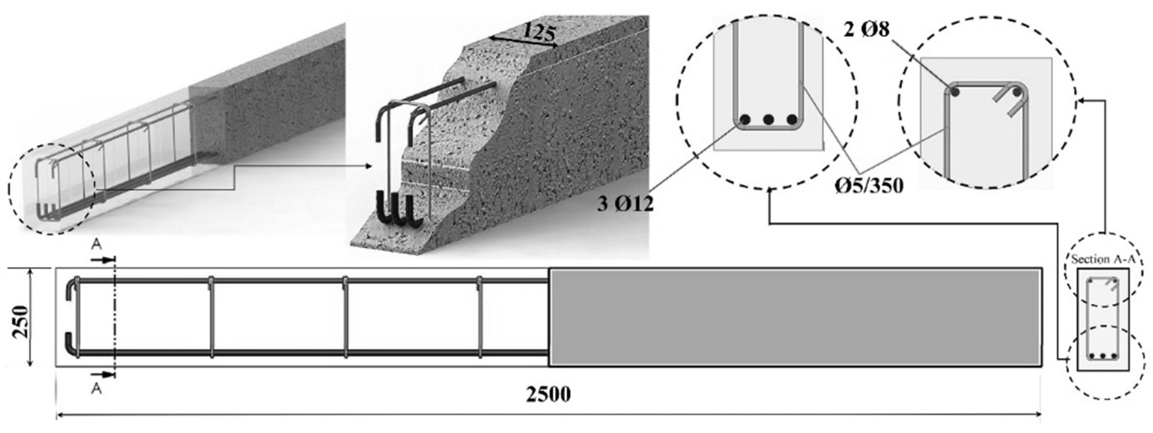
Shear deficient reinforced concrete beams were tested in Konya Technical University Construction and Earthquake Laboratory. The beams produced have a geometric scale of ½ and a cross-sectional area of 125 × 250 mm, and their length was 2500 mm. Details of the beam are shown in Figure 1. Although concrete compressive strength targets 20–25 MPa, the 28-day cylinder concrete compressive strength of the beams was calculated as 29 MPa (between C25 and C30 grade). The splitting tensile strength was determined as 1.3 MPa. B420c type ribbed 3ϕ12 (ρ = 0.0117) longitudinal reinforcement was placed in the bending zone of the beam and 2ϕ8 (ρ’ = 0.00347) longitudinal reinforcement was placed in the compression zone. The reinforcement ratio considered in the design of the beams is higher than the minimum reinforcement ratio (ρmin = 0.00306), according to the Turkish Reinforced Concrete Building Code [79]. In addition, the longitudinal reinforcements were selected in accordance with the under-balance ductile design. The transverse reinforcements were applied as ϕ5/350 mm. On the other hand, stirrup hooks were bent at 90°, which is common and contrary to the regulation. Additionally, 25 mm placers are used in the beams.
2.2. Strengthening Technic by Mechanical Steel Stitches (MSS)
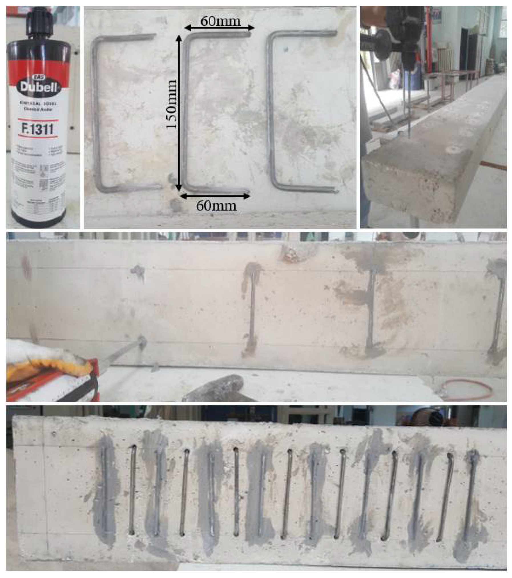
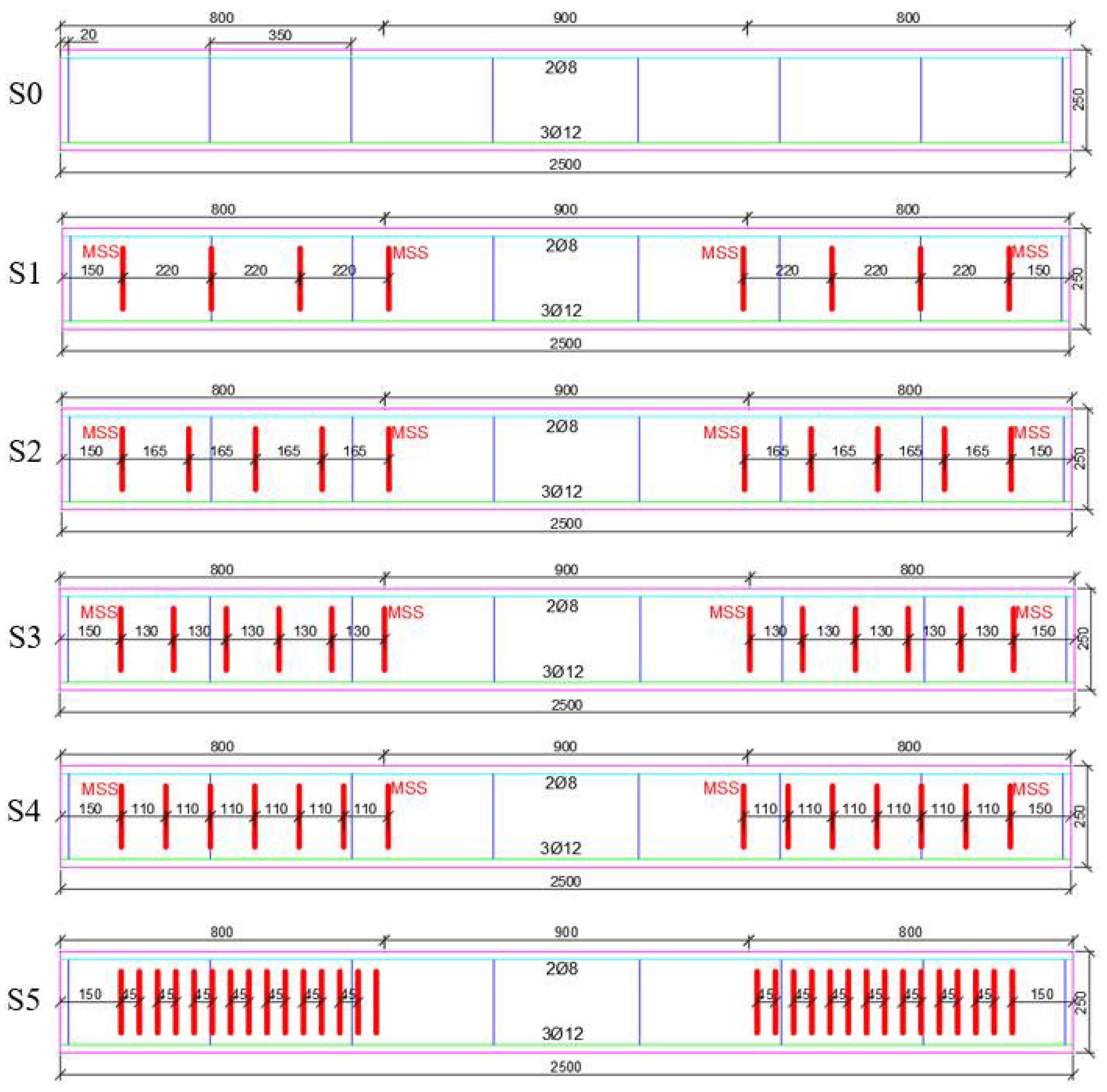
In reinforcement applications, U-type mechanical steel stitches (MSS) were prepared by using a ϕ6 mm diameter cold-formed transmission steel. Each stitch length is 150 mm, and the squares are designed as 60 mm (10ϕ). The points determined on the beam surface to be applied were drilled to a depth of 60 mm with an 8 mm diameter drill (ϕ8), and the holes were filled with Dubell-F.1311 brand epoxy after cleaning with compressed air. Prepared U-type MSSs were placed in the holes drilled on both sides of the beam. According to the manufacturer’s recommendations, after the MSs were fixed to the beams with epoxy, they were left to cure for one day at room temperature (25 °C). The MSSs applied to the shear opening of the beams were applied at 90° in stirrup logic (Figure 2). MS with five different placements was applied to the shear span of the beams (700 mm part). One is the reference (S0), and the other five represent the specimens strengthened by the placement of MSSs with different spacings (Figure 3).
The placed MSSs were applied considering the increasing volumetric ratio (). Here n; number of stirrup arms, A0; stirrup cross-sectional area, bw; beam width and s; MSS represents the application range. Details depending on the MSS diameter (ϕ), spacing (s) and volumetric ratio (ρMS) for beams reinforced with MSSs applied with different spacing are given in Table 2. All the MSSs made were placed perpendicular to the expected crack, taking into account the crack mechanism of the S0 beam at the end of the experiment. MSSs transmit force with the friction force they create between the surfaces to which they are attached. For this, the number and size of MSS are significant for effective strengthening. Therefore, MSSs were prepared considering the remaining height after deducting the rust, longitudinal reinforcement and transverse reinforcement allowances of the MSS beam. MSS application has very important advantages compared to other strengthening methods. First of all, since it is very easy to apply, fewer workers are needed compared to other reinforcement alternatives, and this process can even be carried out with a single worker. It is also the most cost-effective compared to other strengthening methods.
2.3. Test Setup
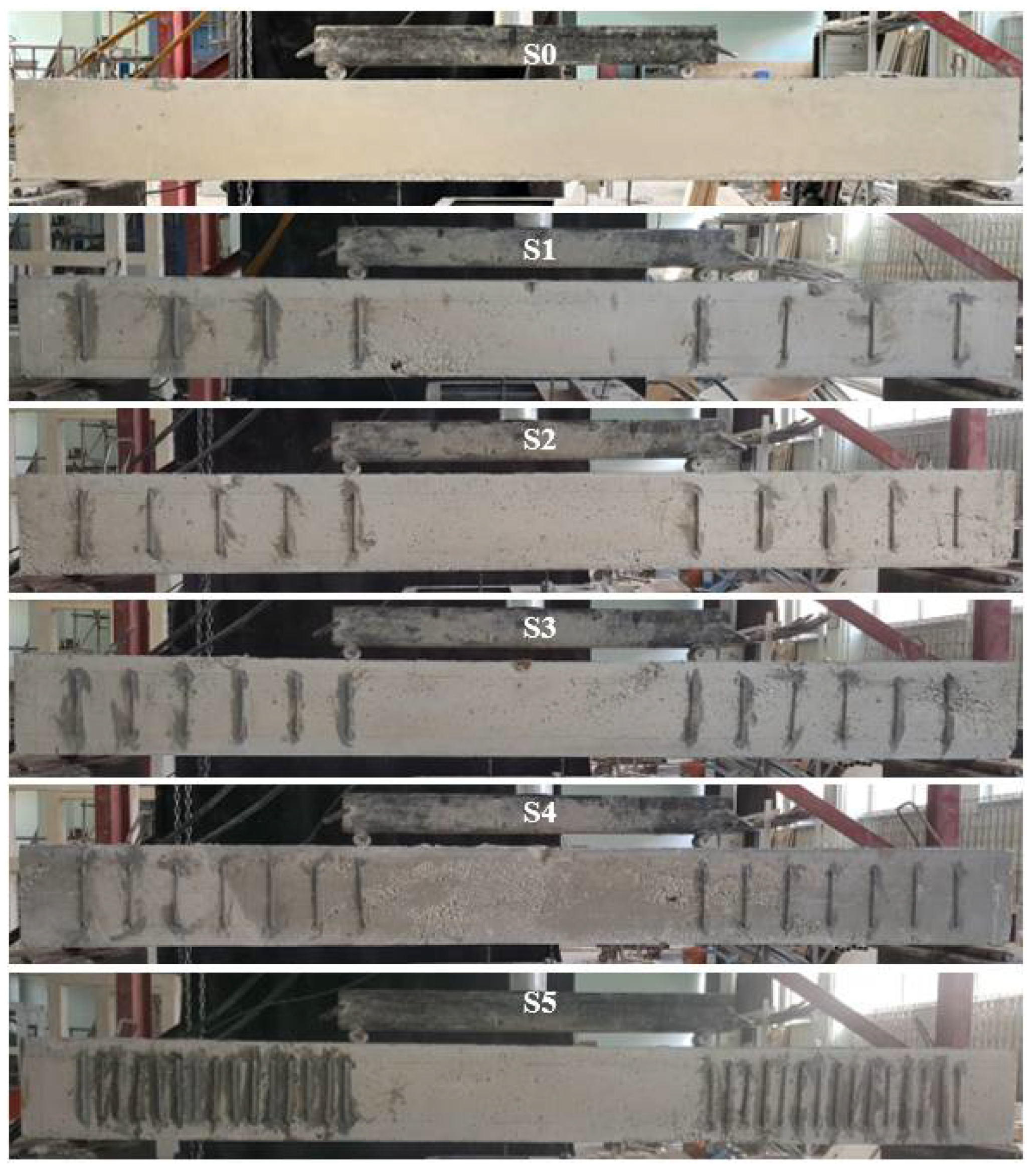
The reference and strengthened specimens were tested under vertical loads in a four-point bending setup in the rigid steel loading frame shown in Figure 4. In Figure 5, the pre-experimental views of each specimen are shown. The beams are simply supported so that 100 mm of them fits on the supports. Since shear damage in the reference beam was desired, the av/d ratio (shear span to depth ratio (70/22.5) (mm/mm)) was chosen as 3.11 [80,81]. In this way, the formation of shear damage was observed in reference S0. The load cell used for loading the beam has a capacity of 300 kN. A load-displacement curve was obtained for each specimen by considering two displacement meters (LVDT) located in the middle of the beam, and the load and the distance between them are 160 mm. All records were recorded with the data collection system. As a result of splitting the load from the vertical piston into two over the spreader beam, a single load transfer is achieved. With vertical monotonic loading, 10 kN increments were continued until the end of the experiments. The experiments continued with displacement control depending on the behavior of the beams at the time of yielding. In the experiments, each monotonic loading was waited for a short time to mark the cracks on the test.
3. Experimental Results and Discussion
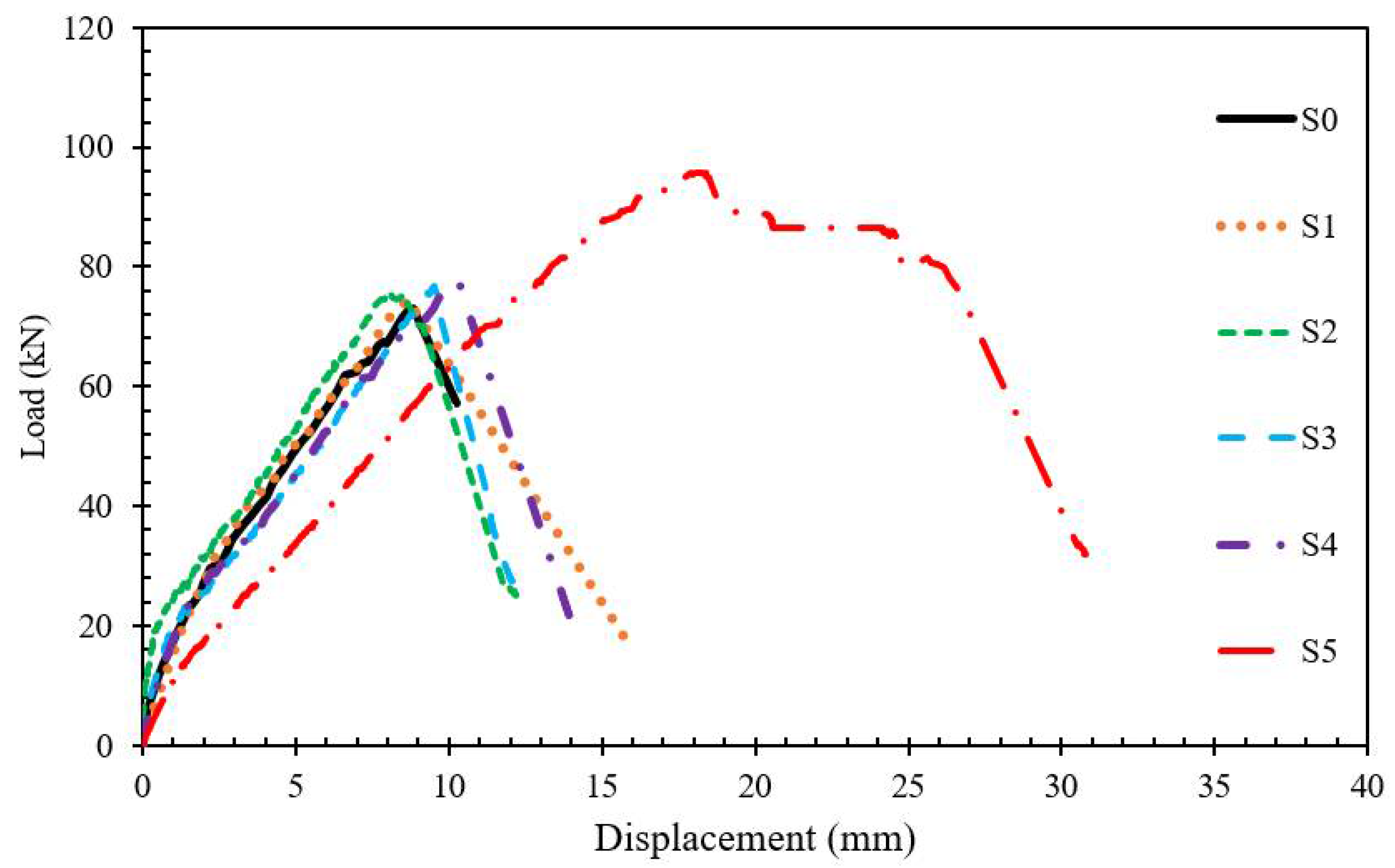
In the experimental study, vertical load-mid-point displacement graphs of each specimen were drawn. By comparing the reference specimen (S0) with the strengthened specimens (S1, S2, S3, S4 and S5), deep discussions on MSS were reached. Comparisons were made step by step with the systematic application of MSSs to the beam. Graphical comparisons were made by considering the increasing volumetric ratio of MSS (ρMS) in strengthening applications. This way, behavior changes and suggestions could be put forward clearly. In the experiments, the number of MSS (4, 5, 6, 7 and 15) applied to the beams was increased step by step. Each experiment was compared with previous experiments, and a cumulative evaluation was made at the end. In other words, the number and range of MSSs were determined by making evaluations before each reinforcement design. All MS applications were performed along the shear span on both sides of the beam. Experimental studies, respectively, are explained in detail and interpreted by comparison. Comparisons are limited by the load carrying capacity, stiffness, ductility and energy dissipation capacity. The test results of all specimens are summarized in Table 3. In addition, the comparison of all specimens is shown in Figure 6. During the whole experiment, no peeling and rupture damage was observed in the MSSs, and shear, bending and adherence damage were observed in the concrete. This also showed that the anchor length (10ϕ = 60 mm) of the applied MSSs was sufficient. At the end of the experiment, comprehensive damage analyzes were performed for each specimen.
3.1. Reference Specimen: S0
The S0 specimen was tested as a reference beam with insufficient shear reinforcement. The vertical load was applied in increments of 10 kN. The first cracks in the experiment were observed in the middle span of the beam (in the bending region) and at the load level of 30 kN. These first cracks represent linear elastic cracks at the minor level. With the load reaching 60 kN, shear cracks observed in beam shear openings occurred below the neutral axis (midpoint of the beam section). With the vertical load of 70 kN and the current displacement of 8.3 mm, the shear cracks extended to the support point under the spreader beam. Finally, when the S0 specimen reached the maximum load level of 73 kN at 8.83 mm displacement, sudden and brittle shear damage occurred in the left shear opening. This showed that the beam design with insufficient shear and the selected av/d ratio were sufficient. A damage analysis view of the beam is given in Figure 7. When the damage analysis is examined, it is seen that typical shear damage occurs. Choosing the stirrup spacing as 350 mm caused the cracks formed in the shear opening of the beam to extend along the beam height with increasing load. The absence of stirrups to limit the propagation of cracks made the occurrence of shear damage inevitable.
3.2. Strengthened Specimens: S1, S2, S3, S4 and S5
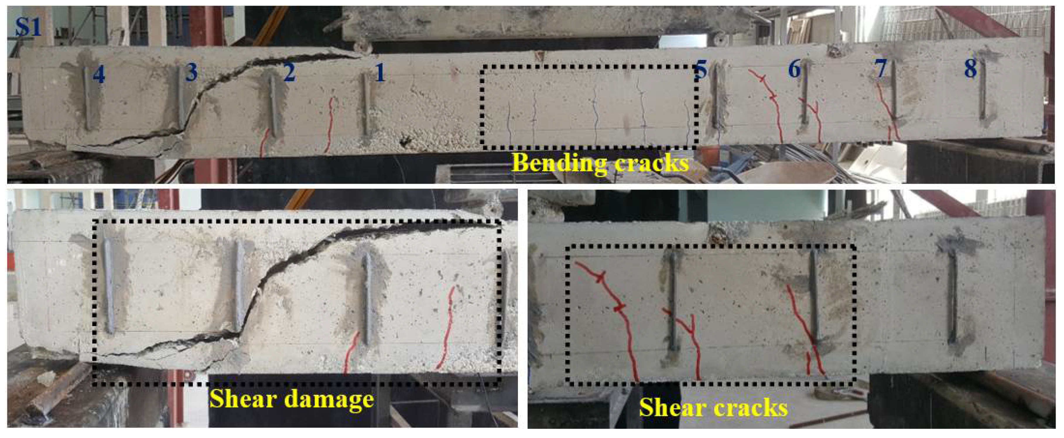
Specimen S1 was strengthened by epoxy application of 4 MSSs with a diameter of 6 mm, a length of 150 mm and an anchor length of 60 mm on one side of the shear opening of the reference beam (S0). In other words, the S1 beam was strengthened by applying a total of sixteen MSS to the beam shear openings. In the experiment, the first minor bending cracks started to appear in the middle span of the beam at a load level of 10 kN. When the load reached 30 kN, a displacement of 2.68 mm occurred in the middle region of the beam. At this load, the minor cracks extended towards the neutral axis. Additionally, as shown in Figure 8, the first capillary shear cracks occurred in the lower left part of MSS 2, just below MSS 5, and finally in the middle of MSS 5 and 6. With the load reaching 40 kN, a new crack occurred in the bending region. In addition, elongation was observed in the shear crack between 5 and 6 MSS at this load value. After this load value, a new shear crack was observed between MSS 1-2 and MSS 6-7 in the shear zone at 50 kN load level. With the load reaching 60 kN, no further elongation or new cracks were observed in the cracks in the bending region. With the load reaching 74.59 kN and the displacement reaching 8.67 mm, shear damage occurred in the left shear opening of the beam, passing through the middle of the MSS 2-3, and the experiment was terminated. Up to a certain value of the load, the crack propagation, which reaches 6 MSS, is prevented by the mechanical stitches. When the damage observed between MSS 2 and 3 in the left shear opening is examined, it is understood that the cracks try to reach the beam pressure zone by the shortest route. As a matter of fact, the angle of the shear damage in the reference sample with the horizontal is less. Here, the presence of MSSs 1 and 2 caused a partial change in the location of the shear damage. In addition, when compared to the S0 specimen, there was an increase of approximately 2.17% in the load-carrying capacity. This shows that the MSSs that are located makes a very small contribution to the load-carrying capacity. Finally, as in the S0 specimen, sufficient ductility could not be achieved in the S1 specimen.
In the S2 specimen, the number of MSS was increased to 5. In this way, the distance between the MSSs has been reduced to 165 mm. The total number of MSSs placed on the beam shear zone is twenty. In the S2 specimen, the first microcracks were observed at the 20 kN load level, that is, at the vertical displacement level of 1.65 mm. These cracks represent elastic cracks. With the vertical load of 30 kN and the displacement value of 2.92 mm, the first shear cracks occurred between the MSSs 6-7 and 7-8. At this load value, it was observed that the cracks in the middle region of the beam were elongated towards the neutral axis, and new cracks were formed. Since the vertical load on the beam reached 50 kN and the displacement value reached 5.26 mm, shear cracks occurred between MSSs 1-2 and 2-3. In addition, bending cracks observed in the middle of the beam at this load value were limited to the neutral axis level. With the load reaching 60 kN and the displacement 6.23 mm, new shear cracks were observed between the MSSs 3-4 and 8-9. Finally, with the load reaching 75.79 kN and the vertical displacement 8.07 mm, shear damage occurred in the right shear opening and the experiment was terminated. It cannot be said that sufficient MSS number and spacing are provided in terms of ductility in the S2 specimen, where shear behavior was observed. However, the load-carrying capacity of the S2 specimen increased by 3.8% and 1.6%, respectively, compared to the S0 and S1 specimens. MSSs applied to the S2 specimen did not significantly contribute to the bending stiffness of the beams. This indicates that due to the fact that the shear capacity does not increase significantly, it can respond to less rotational demand and that the longitudinal reinforcements in the tension zone do not yield. The damage of the S2 specimen at the end of the test is shown in Figure 9. When Figure 9 is examined, the failure has migrated between MSSs 8 and 9. The shear damage in S2 is quite similar to the damage in S1. Reducing the MS gap in the S2 specimen partially changed the path of the crack. However, if it is taken into account, the occurrence of shear damage passing through the upper part of the MSS 8 and the lower point of the MSS 9 showed that the cracks were directed to the damaged points by drilling holes beforehand. This shows that there should be MSSs that prevent the propagation of cracks. Since this situation is thought to be possible only by reducing the MSS interval, the following test specimen was prepared.
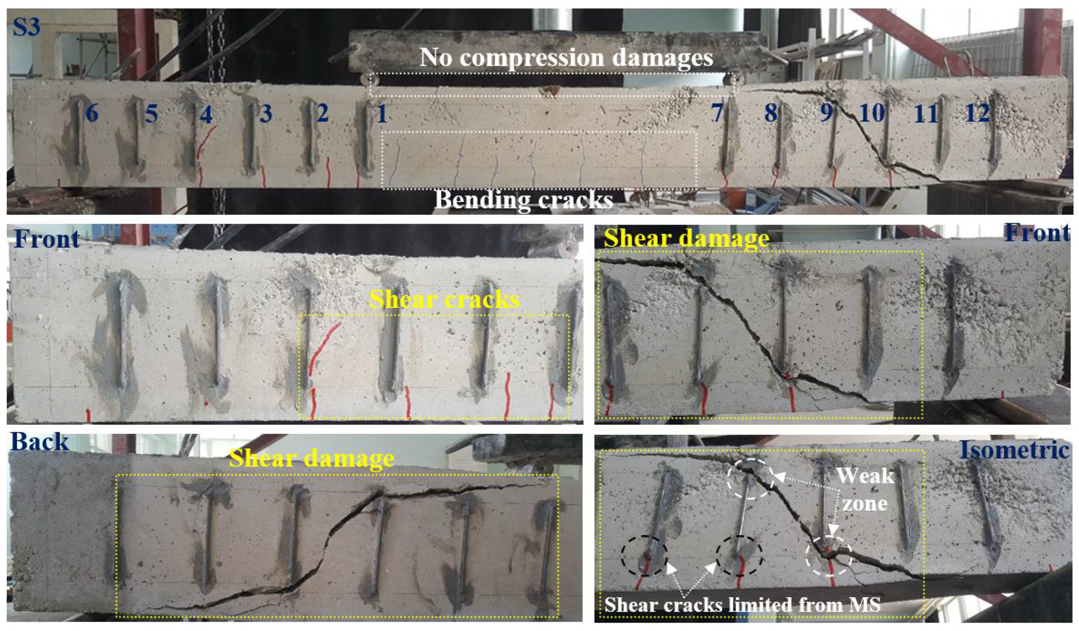
Although the MSSs placed in the S2 increased the load carrying capacity slightly, the S3 was created because they could not prevent shear damage. The total number of MSS placed in the S3 sample is twenty-four. The distance between each MSS was set to 130 mm. The aim here is to prevent the shear cracks to be formed by more MSS. For this, the first three bending cracks were observed in the middle of the beam with monotonic increasing loads and a load of 20 kN and a displacement of 1.95 mm (Figure 10). Cracks continued to increase in the bending zone as the load reached 30 kN and the displacement reached 3.98 mm. In addition, the first shear crack occurred at this load value between the 1-2 and 2-3 numbered MSSs in the left shear span. With a load of 50 kN and a displacement of 5.74 mm, minor shear cracks were observed at the lower points of MSSs 4, 7, 8 and 9. No propagation was observed in bending cracks at the neutral axis level at this load level. This indicates that the shear capacity is more difficult. With a load of 70 kN and a displacement of 7.34 mm, a minor shear crack started from the lower part of the MSS 4 and along the height of the MSS. This crack did not propagate in subsequent loadings. At this load level, the increase in minor shear cracks, especially in the right and left shear span, indicates that the shearing capacity is approached. Finally, with the load of 76.90 kN and the displacement of 9.53 mm, shear damage occurred with the propagation of the crack between the MSS 9-10 in the left shear span. Particularly, the weak areas at the upper point of MSS 9 and the lower point of MSS 10 accelerated the progression of the crack. In terms of load carrying capacity, the S3 increased by 5.34%, 3.08% and 1.45%, respectively, compared to S0, S1 and S2. The fact that sufficient ductility value could not be obtained with the increase in load carrying capacity showed that the number of MSS should be increased.
Since the desired ductile behavior could not be obtained in the S3, the MSS spacing was reduced to 110 mm. In this way, more MSS was applied to prevent possible shear damage that may occur in the shear zone. In other words, shear damage was tried to be prevented with seven MSSs placed on one side of the shear opening of the designed S4 specimen. In this way, the behavior change was investigated with a total of twenty-eight MSSs applied to the beam. In this loading, the first crack similarly occurred in the bending region at a load of 30 kN and a displacement of 3.63 mm. When the load is 40 kN and the displacement is 5.23 mm, the first shear crack was observed between MSS 3 and 4. When the load is 60 kN and the displacement is 7.16 mm, a shear crack occurred between MSS 1-2, 2-3 and the lower right of the MSS 10. The crack, which started under the MSS 13 with a vertical load of 70 kN and a displacement of 8 mm, progressed between MSS 11 and 12 and reached the upper cap (Figure 11). Finally, shear damage occurred when the vertical displacement reached 10.17 mm and the vertical load reached 78.10 kN. The load carrying capacity of the S4 increased by 6.98%, 4.69%, 3.03% and 1.56%, respectively, compared to the S0, S1, S2 and S3. However, since the ductility ratio was calculated as 1.36, it can also be said for S4 that sufficient ductility could not be obtained according to the literature. Although the load carrying capacity of the S1, S2, S3 and S4 obtained by strengthening the S0 up to this stage was relatively increased, the inability to obtain ductile behavior indicates that the MSSs do not work in the stirrup logic existing in the beam. The number of stitches was applied as 4 (range 220 mm), 5 (range 165 mm), 6 (range 130 mm) and 7 (range 110 mm) on one side in the shear area until this stage, but it was thought that more frequent MSS should be applied since shear damage could not be prevented. Since the crack formed in the shear zone at each step reached the beam’s upper head between the two MSS in the shortest way and caused the formation of shear damage.
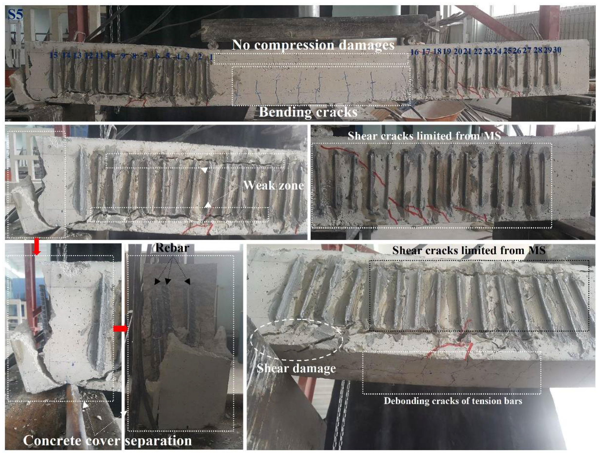
Finally, the S5 was prepared in order to strengthen the S0 beam. The difference between S-5 from other reinforcement types was that the most frequent (range 45 mm) MSS application was made along the shear opening. In this way, the behavior of MSSs placed in the stirrup logic in the most common situation was clearly seen. For this, fifteen MSS were applied to one side of the shear opening. In this way, the beam was strengthened using a total of 60 MSS. Initial bending cracks were observed for the S5 specimen at a load of 20 kN and a displacement of 2.56 mm. With the load of 30 kN and the displacement of 4.43 mm, the elongation of the cracks in the bending region was observed. In addition, at this load value, the first shear crack occurred in the right shear span of the beam, just below the 26 numbered MSS. With the increase in the load, new cracks were formed in the beam bending region with a load of 40 kN and a displacement of 6.16 mm and the elongation in the existing cracks continued. This was evaluated as a sign that the applied MSSs increased the shear capacity and forced the bending region of the beam. In addition, a shear crack was observed under the MSS 7 in the left shear opening at this load value. With the load reaching 50 kN and the displacement 7.94 mm, new cracks were formed in the bending region and elongation was observed in the existing cracks. When the load reached 60 kN and 9.47 mm, the cracks in the bending zone reached the neutral axis level. In addition, a shear crack was observed just below MSSs 1 and 22. With the increase in the vertical load, the 19-20-21 MSSs with 70 kN load and 11.27 mm displacement tried to prevent the propagation of shear cracks. At this load, new bending cracks also formed and moved towards the neutral axis. This showed that bending reinforcements started to yield at this load value. When the load reached 80 kN and the displacement reached 13.69 mm, the crack reaching MSS 19 advanced towards MSS 18. The propagation of cracks in the right shear span indicates that the shear capacity was forced. In addition, the fact that it continues to elongate in the cracks in the bending region at this load value shows that the longitudinal reinforcements are also forced. As the load reached 90 kN and the displacement reached 16.45 mm, the propagation of the cracks in the bending zone stopped. The crack reaching the number 18 MSS progressed and advanced to the bottom of the spreader beam right support. In addition, shear cracks were observed under MSSs 7 and 8 in the left shear opening at this load value. Finally, with the load reaching 95.74 kN and the displacement 17.89 mm, the load carrying capacity suddenly decreased and the experiment was terminated. It was observed in Figure 12 that cracks progressed on a horizontal line in the upper and lower parts of the MSSs in the left shear span. Due to the application of the applied MSSs between the lower and upper reinforcement, cracks developed from the weakest link. The MSSs present in the left shear span prevented the cracks from expanding and causing shear damage. Therefore, the support area, which was not reinforced, was broken by remaining weaker. When the specimen was examined, the test was terminated by the fracture of the weaker shell concrete than the point where the longitudinal reinforcements in the support area just ended. As a result, it can be said that the applied MSSs prevent the beam from direct shear damage. Considering the load carrying capacity, the S5 showed an increase of 31.15%, 28.33%, 26.30%, 24.49% and 22.58%, respectively, compared to the S0, S1, S2, S3 and S4 specimens.
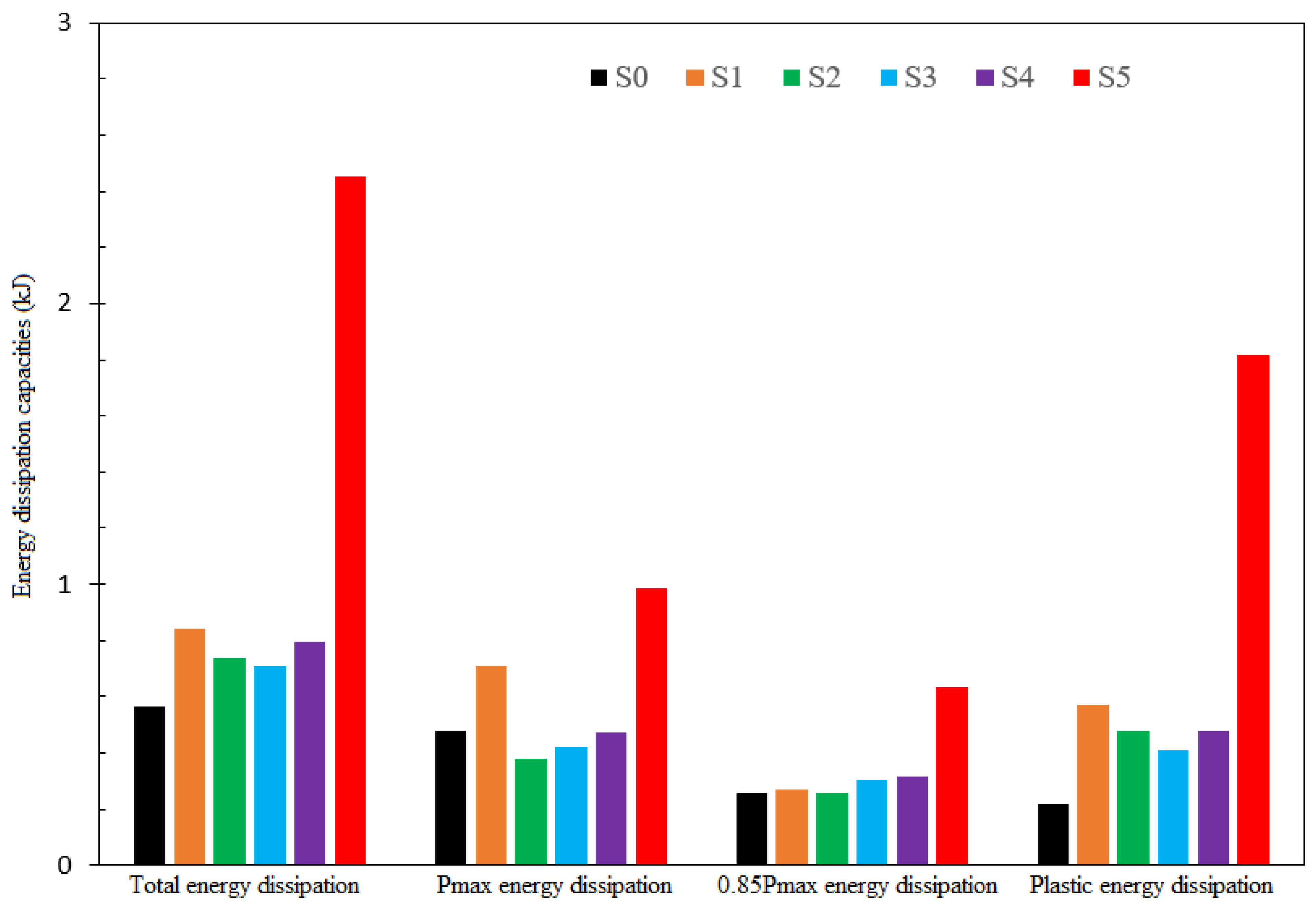
The energy dissipation capacities of each specimen are given in Figure 13 and Figure 14 and Table 4 and Table 5. When compared in terms of elastic energy dissipation, the S5 specimen showed an increase of 142.30%, 133.33%, 142.30%, 110% and 103.22%, respectively, compared to the S0, S1, S2, S3 and S4 specimens. This shows that the energy dissipation temporarily stored in the linear elastic behavior of the S5 specimen is the highest compared to other strengthening methods. In other words, it shows that the elastic energy dissipation capacity of the S5 specimen is better under sudden vertical load effects. The energy dissipated after damage to the building elements, especially under forced effects such as earthquakes, is known as plastic energy. In this respect, the S5 specimen has a higher plastic energy dissipation capacity. In other words, the S5 specimen has 8.62 times, 3.17 times, 3.85 times, 4.52 times and 3.85 times more plastic energy dissipation capacity than S0, S1, S2, S3 and S4 specimens, respectively. Although the S5 specimen has the highest plastic energy dissipation capacity among the reinforcement alternatives, it can be said that this is not at a sufficient level when evaluated with ductility, especially the high plastic energy dissipation capacity in S5 is due to the frequency of applied MSS. If this situation is considered to be applied to the beams in the stirrup logic, it should be applied at maximum 45 mm intervals. It should be noted that otherwise, direct shear damage to the beam will occur.
4. Conclusions
There are many different strategies (including the use of external steel reinforcement, section enlargement, internal steel or FRP reinforcement, supplemental members, FRP plates and strips, both steel and FRP NSMR, and external pre-stressing) in the conventional strengthening or retrofitting of existing reinforced concrete buildings. The strategies chosen vary in relation to the expected behavior of the existing reinforced concrete member. In this study, U-shaped Mechanical Steel Stitches (MSS) have been tested for the first time in the literature, especially for reinforced concrete beams where brittle fracture is expected under shear. The performance of MSSs applied over the cracks of damaged reinforced concrete elements, which were previously conducted in the literature, was tested on undamaged reinforced concrete beams in this study. In the experimental study carried out on six reinforced concrete beams, while the mechanical properties of the existing beam and MS were kept constant, the only variable was the application range (spacing) of MSSs. The findings obtained from the experimental study are as follows;
- (1)
- As expected, shear failure occurred in the reference S0 beam. On the other hand, shear failure could not be prevented in S1, S2, S3 and S4 beams, where the MSS spacing gradually changes between d and d/2. It has been observed that the cracks formed in the range of 45°–60°. In the S5 specimen, where the MSS range was d/5 ((1%) MSS ratio), crack formation did not occur with this angle. Therefore, it can be concluded that tightening the spacing of MS would be helpful in preventing the shear fracture of the beams.
- (2)
- Since the MSs are attached to the existing reinforced concrete beam with anchors, some losses in section due to the drilling have occurred in the stiffness of the existing beams. For example, a 38% loss in initial stiffness occurred in S5 compared to S0. This situation slightly increased the amount of deflection occurring in the span of the beam. Especially in MSS application, micro-cracks formed during the drilling of existing beams merged due to the close proximity of the holes, and a damage mechanism similar to an adherence crack was observed.
- (3)
- While the capacity increase in S1, S2, S3 and S4 beams was limited compared to S0, a gain of nearly 31% occurred in the S-5 beam. However, a load carrying capacity increase depending on the d/s amount (s is spacing between MS) was not observed in the experiments. This situation is also related to the formation of cracks in the d to d/2 range without coinciding with the MSSs.
- (4)
- The energy consumed (absorbed) by the beams S1, S2, S3 and S4 increased gradually compared to the reference beam S0. In addition, with the considerable increase in strength, the energy consumption of the S5 beam increased approximately 4 times compared to the S0 beam. The increase in displacement due to the decrease in stiffness of the S-5 beam had an effect on this increase.
- (5)
- Experimental results show that the RC beams strengthened with different MSS configurations as S1, S2, S3, and S4 have a modest increase in failure load. It would also seem that in terms of ductility the arrangement of the pins up to a spacing of 110 mm is negligible. On the other hand, the S5 MSS configuration allows a considerable increase in the ultimate load. Therefore, it is concluded that a certain level of spacing is quite critical in this novel external strengthening method.
- (6)
- It has been seen that the method proposed in this study can be used for strengthening purposes, especially in the RC members under the effect of shear, when traditional strengthening methods are not suitable in terms of cost, application, and time. Therefore, the outcomes of this study will be frontiers for new studies to be carried out for the optimum design of MSSs, which is not in the existing codes and is a fairly new retrofit/strengthening alternative for the literature.
- (7)
- In this study, MSSs applied angle, MS diameter, anchorage depth and mechanical properties were kept constant. Therefore, the effect of these parameters on the behavior of beams reinforced with MS should be investigated in future studies. Similarly, the mechanical properties of the beams, stirrups and longitudinal reinforcement amounts, beam’ geometric shapes, loading patterns, etc., are also waiting as an important research topic in MSS-reinforced beams.
- (8)
- In addition to the above-mentioned positive features, it is quite possible that MSSs will be exposed to corrosion over time due to their properties. For this, it is very important that the outside of the material is covered with a corrosion inhibitor in the strengthening to be made. In addition, in future studies, MSS applications can also be made with FRP materials. In this way, the corrosion situation is eliminated.
Author Contributions
Conceptualization, C.A., Y.O.Ö. and M.H.A.; methodology, C.A., Y.O.Ö. and M.H.A.; formal analysis, C.A., Y.O.Ö. and M.H.A.; investigation, C.A., Y.O.Ö. and M.H.A.; data curation, C.A., writing—original draft preparation, C.A., writing—review and editing, C.A., Y.O.Ö. and M.H.A.; funding acquisition, C.A, Y.O.Ö. and M.H.A. All authors have read and agreed to the published version of the manuscript.
Funding
The study was supported by the Scientific and Technological Council of Turkey (TÜBİTAK) through grant number 122M091. The opinions expressed in this paper are those of the authors and do not reflect the views of the sponsor.
Institutional Review Board Statement
Not applicable.
Informed Consent Statement
Not applicable.
Data Availability Statement
Not applicable.
Conflicts of Interest
The authors declare no conflict of interest.
References
- Bousias, S.N.; Biskinis, D.; Fardis, M.N.; Spathis, A.-L. Strength, stiffness, and cyclic deformation capacity of concrete jacketed members. ACI Struct. J. 2007, 104, 521. [Google Scholar]
- Altun, F. An experimental study of the jacketed reinforced-concrete beams under bending. Constr. Build. Mater. 2004, 18, 611–618. [Google Scholar] [CrossRef]
- Bayülke, N. Structural Damage on 27 June 1998 Adana-Ceyhan Earthquake; General Directorate of Disaster Affairs, ERD: New Delhi, India, 1998. [Google Scholar]
- Korkmaz, H.H.; Dere, Y.; Özkılıç, Y.O.; Bozkurt, M.B.; Ecemiş, A.S.; Özdoner, N. Excessive snow induced steel roof failures in Turkey. Eng. Fail. Anal. 2022, 141, 106661. [Google Scholar] [CrossRef]
- Özkılıç, Y.O.; Aksoylu, C.; Arslan, M.H. Numerical evaluation of effects of shear span, stirrup spacing and angle of stirrup on reinforced concrete beam behaviour. Struct. Eng. Mech. Int’l. J. 2021, 79, 309–326. [Google Scholar]
- Gemi, L.; Madenci, E.; Özkılıç, Y.O.; Yazman, Ş.; Safonov, A. Effect of Fiber Wrapping on Bending Behavior of Reinforced Concrete Filled Pultruded GFRP Composite Hybrid Beams. Polymers 2022, 14, 3740. [Google Scholar] [CrossRef]
- Gemi, L.; Madenci, E.; Özkılıç, Y.O. Experimental, analytical and numerical investigation of pultruded GFRP composite beams infilled with hybrid FRP reinforced concrete. Eng. Struct. 2021, 244, 112790. [Google Scholar] [CrossRef]
- Özkılıç, Y.O.; Aksoylu, C.; Yazman, Ş.; Gemi, L.; Arslan, M.H. Behavior of CFRP-strengthened RC beams with circular web openings in shear zones: Numerical study. Structures 2022, 41, 1369–1389. [Google Scholar] [CrossRef]
- Arslan, M.H.; Yazman, Ş.; Hamad, A.A.; Aksoylu, C.; Özkılıç, Y.O.; Gemi, L. Shear strengthening of reinforced concrete T-beams with anchored and non-anchored CFRP fabrics. Structures 2022, 39, 527–542. [Google Scholar] [CrossRef]
- Özkılıç, Y.O.; Yazman, Ş.; Aksoylu, C.; Arslan, M.H.; Gemi, L. Numerical investigation of the parameters influencing the behavior of dapped end prefabricated concrete purlins with and without CFRP strengthening. Constr. Build. Mater. 2021, 275, 122173. [Google Scholar] [CrossRef]
- Gemi, L.; Aksoylu, C.; Yazman, Ş.; Özkılıç, Y.O.; Arslan, M.H. Experimental investigation of shear capacity and damage analysis of thinned end prefabricated concrete purlins strengthened by CFRP composite. Compos. Struct. 2019, 229, 111399. [Google Scholar] [CrossRef]
- Raza, S.; Khan, M.K.; Menegon, S.J.; Tsang, H.-H.; Wilson, J.L. Strengthening and repair of reinforced concrete columns by jacketing: State-of-the-art review. Sustainability 2019, 11, 3208. [Google Scholar] [CrossRef]
- More, R.U.; Kulkarni, D. Flexural behavioural study on RC beam with externally bonded aramid fiber reinforced polymer. Int. J. Res. Eng. Technol. 2014, 3, 316–321. [Google Scholar]
- Wu, B.; Zhang, S.; Liu, F.; Gan, T. Effects of salt solution on mechanical behaviors of aramid fiber–reinforced polymer (AFRP) sheets and AFRP-to-concrete joints. Adv. Struct. Eng. 2016, 19, 1855–1872. [Google Scholar] [CrossRef]
- Zhang, S.; Wu, B. Effects of salt solution on the mechanical behavior of concrete beams externally strengthened with AFRP. Constr. Build. Mater. 2019, 229, 117044. [Google Scholar] [CrossRef]
- Raval, C.; Shah, S.; Machhi, C. Experimental Study on Shear Behaviour of RC Beam Strengthened by AFRP Sheet. Int. J. All Res. Writ. 2020, 3, 62–68. [Google Scholar]
- Ma, C.-K.; Apandi, N.M.; Sofrie, C.S.Y.; Ng, J.H.; Lo, W.H.; Awang, A.Z.; Omar, W. Repair and rehabilitation of concrete structures using confinement: A review. Constr. Build. Mater. 2017, 133, 502–515. [Google Scholar] [CrossRef]
- Ma, G.; Li, H.; Yan, L.; Huang, L. Testing and analysis of basalt FRP-confined damaged concrete cylinders under axial compression loading. Constr. Build. Mater. 2018, 169, 762–774. [Google Scholar] [CrossRef]
- Qin, Z.; Tian, Y.; Li, G.; Liu, L. Study on bending behaviors of severely pre-cracked RC beams strengthened by BFRP sheets and steel plates. Constr. Build. Mater. 2019, 219, 131–143. [Google Scholar] [CrossRef]
- Duic, J.; Kenno, S.; Das, S. Flexural rehabilitation and strengthening of concrete beams with BFRP composite. J. Compos. Constr. 2018, 22, 04018016. [Google Scholar] [CrossRef]
- Joyklad, P.; Suparp, S.; Hussain, Q. Flexural response of JFRP and BFRP strengthened RC beams. Int. J. Eng. Technol. 2019, 11, 203–207. [Google Scholar] [CrossRef]
- Pham, T.M.; Chen, W.; Elchalakani, M.; Karrech, A.; Hao, H. Experimental investigation on lightweight rubberized concrete beams strengthened with BFRP sheets subjected to impact loads. Eng. Struct. 2020, 205, 110095. [Google Scholar] [CrossRef]
- Shen, D.; Li, M.; Kang, J.; Liu, C.; Li, C. Experimental studies on the seismic behavior of reinforced concrete beam-column joints strengthened with basalt fiber-reinforced polymer sheets. Constr. Build. Mater. 2021, 287, 122901. [Google Scholar] [CrossRef]
- Prado, D.M.; Araujo, I.D.G.; Haach, V.G.; Carrazedo, R. Assessment of shear damaged and NSM CFRP retrofitted reinforced concrete beams based on modal analysis. Eng. Struct. 2016, 129, 54–66. [Google Scholar] [CrossRef]
- Karzad, A.S.; Al Toubat, S.; Maalej, M.; Estephane, P. Repair of reinforced concrete beams using carbon fiber reinforced polymer. In Proceedings of the MATEC Web of Conferences: EDP Sciences 2017, Sharjah, United Arab Emirates, 18–20 April 2017; p. 01008. [Google Scholar]
- Karam, E.C.; Hawileh, R.A.; El Maaddawy, T.; Abdalla, J.A. Experimental investigations of repair of pre-damaged steel-concrete composite beams using CFRP laminates and mechanical anchors. Thin-Walled Struct. 2017, 112, 107–117. [Google Scholar] [CrossRef]
- Karzad, A.S.; Leblouba, M.; Al Toubat, S.; Maalej, M. Repair and strengthening of shear-deficient reinforced concrete beams using Carbon Fiber Reinforced Polymer. Compos. Struct. 2019, 223, 110963. [Google Scholar] [CrossRef]
- Yu, F.; Zhou, H.; Jiang, N.; Fang, Y.; Song, J.; Feng, C.; Guan, Y. Flexural experiment and capacity investigation of CFRP repaired RC beams under heavy pre-damaged level. Constr. Build. Mater. 2020, 230, 117030. [Google Scholar] [CrossRef]
- Yu, F.; Fang, Y.; Zhou, H.; Bai, R.; Xie, C. A Simplified Model for Crack Width Prediction of Flexural-Strengthened High Pre-Damaged Beams with CFRP Sheet. KSCE J. Civ. Eng. 2020, 24, 3746–3764. [Google Scholar] [CrossRef]
- Yu, F.; Fang, Y.; Guo, S.; Bai, R.; Yin, L.; Mansouri, I. A simple model for maximum diagonal crack width estimation of shear-strengthened pre-damaged beams with CFRP strips. J. Build. Eng. 2021, 41, 102716. [Google Scholar] [CrossRef]
- Bahij, S.; Omary, S.; Feugeas, F.; Faqiri, A. Structural Strengthening/Repair of Reinforced Concrete (RC) Beams by Different Fiber-Reinforced Cementitious Materials-A State-of-the-Art Review. J. Civ. Environ. Eng. 2020, 10. [Google Scholar] [CrossRef]
- Zaki, M.A.; Rasheed, H.A.; Alkhrdaji, T. Performance of CFRP-strengthened concrete beams fastened with distributed CFRP dowel and fiber anchors. Compos. Part B Eng. 2019, 176, 107117. [Google Scholar] [CrossRef]
- Aksoylu, C.; Özkılıç, Y.O.; Yazman, Ş.; Gemi, L.; Arslan, M.H. Experimental and Numerical Investigation of Load Bearing Capacity of Thinned End Precast Purlin Beams and Solution Proposals. Tek. Dergi 2021, 3, 10823–10858. [Google Scholar]
- Al-Khafaji, A.; Salim, H.; El-Sisi, A. Behavior of RC Beams Strengthened with CFRP Sheets under Sustained Loads; Elsevier: Amsterdam, The Netherlands, 2021; pp. 4690–4700. [Google Scholar]
- Kotynia, R.; Oller, E.; Marí, A.; Kaszubska, M. Efficiency of shear strengthening of RC beams with externally bonded FRP materials–State-of-the-art in the experimental tests. Compos. Struct. 2021, 267, 113891. [Google Scholar] [CrossRef]
- Abed, M.J.; Fayyadh, M.M.; Khaleel, O.R. Effect of web opening diameter on performance and failure mode of CFRP repaired RC beams. Mater. Today Proc. 2021, 42, 388–398. [Google Scholar] [CrossRef]
- Al-Fakih, A.; Hashim, M.H.M.; Alyousef, R.; Mutafi, A.; Sabah, S.H.A.; Tafsirojjaman, T. Cracking Behavior of Sea Sand RC Beam Bonded Externally with CFRP Plate; Elsevier: Amsterdam, The Netherlands, 2021; pp. 1578–1589. [Google Scholar]
- Jahami, A.; Temsah, Y.; Khatib, J.; Baalbaki, O.; Kenai, S. The behavior of CFRP strengthened RC beams subjected to blast loading. Mag. Civ. Eng. 2021, 3, 10309. [Google Scholar]
- Alhassan, M.; Al-Rousan, R.; Ababneh, A. Anchoring of the main CFRP sheets with transverse CFRP strips for optimum upgrade of RC Beams: Parametric experimental study. Constr. Build. Mater. 2021, 293, 123525. [Google Scholar] [CrossRef]
- Samb, N.; Chaallal, O.; El-Saikaly, G. Multilayer versus monolayer externally bonded CFRP sheets for shear strengthening of concrete T-Beams. J. Compos. Constr. 2021, 25, 04021025. [Google Scholar] [CrossRef]
- Mukhtar, F.M.; Shehadah, M.E. Shear behavior of flexural CFRP-strengthened RC beams with crack-induced delamination: Experimental investigation and strength model. Compos. Struct. 2021, 268, 113894. [Google Scholar] [CrossRef]
- Mansour, W. Numerical analysis of the shear behavior of FRP-strengthened continuous RC beams having web openings. Eng. Struct. 2021, 227, 111451. [Google Scholar] [CrossRef]
- Gemi, L.; Alsdudi, M.; Aksoylu, C.; Yazman, S.; Ozkilic, Y.O.; Arslan, M.H. Optimum amount of CFRP for strengthening shear deficient reinforced concrete beams. Steel Compos. Struct. 2022, 43, 735–757. [Google Scholar]
- Siddika, A.; Al Mamun, M.A.; Alyousef, R.; Amran, Y.M. Strengthening of reinforced concrete beams by using fiber-reinforced polymer composites: A review. J. Build. Eng. 2019, 25, 100798. [Google Scholar] [CrossRef]
- Capozucca, R.; Magagnini, E.; Vecchietti, M.V.; Khatir, S. RC beams damaged by cracking and strengthened with NSM CFRP/GFRP rods. Frat. Ed Integrità Strutt. 2021, 15, 386–401. [Google Scholar] [CrossRef]
- Panigrahi, A.K.; Biswal, K.; Barik, M. Strengthening of shear deficient RC T-beams with externally bonded GFRP sheets. Constr. Build. Mater. 2014, 57, 81–91. [Google Scholar] [CrossRef]
- Boumaaza, M.; Bezazi, A.; Bouchelaghem, H.; Benzennache, N.; Amziane, S.; Scarpa, F. Behavior of pre-cracked deep beams with composite materials repairs. Struct. Eng. Mech. 2017, 63, 575–583. [Google Scholar]
- Aksoylu, C. Experimental analysis of shear deficient reinforced concrete beams strengthened by glass fiber strip composites and mechanical stitches. Steel Compos. Struct. Int. J. 2021, 40, 267–285. [Google Scholar]
- Rahman, Z. Strength and ductility behaviour of FRC beams strengthened with externally bonded GFRP laminates. Mater. Today: Proc. 2021, 37, 2542–2546. [Google Scholar]
- Kumari, A.; Nayak, A. Strengthening of shear deficient RC deep beams using GFRP sheets and mechanical anchors. Can. J. Civ. Eng. 2021, 48, 1–15. [Google Scholar] [CrossRef]
- Ali, H.; Assih, J.; Li, A. Flexural capacity of continuous reinforced concrete beams strengthened or repaired by CFRP/GFRP sheets. Int. J. Adhes. Adhes. 2021, 104, 102759. [Google Scholar] [CrossRef]
- Abbass, M.; Medhlom, M.; Ali, I. Strength Capacity Cracks Propagations Deflection and Tensile Enhancement of Reinforced Concrete Beams Warped by Glass Fiber Reinforced Polymer Strips. Int. J. Eng. 2021, 34, 1094–1104. [Google Scholar]
- Miruthun, G.; Vivek, D.; Remya, P.; Elango, K.; Saravanakumar, R.; Venkatraman, S. Experimental investigation on strengthening of reinforced concrete beams using GFRP laminates. Mater. Today: Proc. 2021, 37, 27448. [Google Scholar] [CrossRef]
- Al-Shalif, S.A.; Akın, A.; Aksoylu, C.; Arslan, M.H. Strengthening of Shear-Critical Reinforced Concrete T-Beams with Anchored and Non-Anchored GFRP Fabrics Applications; Elsevier: Amsterdam, The Netherlands, 2022; pp. 809–827. [Google Scholar]
- Peng, J.; Tang, H.; Zhang, J. Structural behavior of corroded reinforced concrete beams strengthened with steel plate. J. Perform. Constr. Facil. 2017, 31, 04017013. [Google Scholar] [CrossRef]
- Kazem, H.; Rizkalla, S.; Kobayashi, A. Shear strengthening of steel plates using small-diameter CFRP strands. Compos. Struct. 2018, 184, 78–91. [Google Scholar] [CrossRef]
- Alam, M.A.; Onik, S.A.; Mustapha, K.N.B. Crack based bond strength model of externally bonded steel plate and CFRP laminate to predict debonding failure of shear strengthened RC beams. J. Build. Eng. 2020, 27, 100943. [Google Scholar] [CrossRef]
- Aykac, S.; Özbek, E. Strengthening of reinforced concrete T-beams with steel plates. Tek. Dergi 2011, 22. [Google Scholar]
- Acar, D. Çelik Levha ve Karbon Kumaşlarla Güçlendirilmiş Betonarme Kirişlerin Davranış ve Dayanımı. Master Thesis, Gazi University, Ankara, Turkey, 2014. [Google Scholar]
- Aykaç, B.; Acar, D. Betonarme Kirişlerin Dıştan Yapıştırılmış Karbon Kumaş Ve Çelik Levhalardan Oluşan Kompozit Malzemeyle Güçlendirilmesi. J. Fac. Eng. Archit. Gazi Univ. 2014, 29, 1. [Google Scholar] [CrossRef]
- Abdul-Razzaq, K.S.; Ali, H.I.; Abdul-Kareem, M.M. A new strengthening technique for deep beam openings using steel plates. Int. J. Appl. Eng. Res. 2017, 12, 15935–15947. [Google Scholar]
- Demir, A.; Ercan, E.; Demir, D.D. Strengthening of reinforced concrete beams using external steel members. Steel Compos. Struct. 2018, 27, 453–464. [Google Scholar]
- Osman, B.H.; Wu, E.; Ji, B.; Abdulhameed, S.S. Repair of Pre-cracked Reinforced Concrete (RC) Beams with Openings Strengthened Using FRP Sheets Under Sustained Load. Int. J. Concr. Struct. Mater. 2017, 11, 171–183. [Google Scholar] [CrossRef]
- Xu, C.-X.; Peng, S.; Deng, J.; Wan, C. Study on seismic behavior of encased steel jacket-strengthened earthquake-damaged composite steel-concrete columns. J. Build. Eng. 2018, 17, 154–166. [Google Scholar] [CrossRef]
- Xu, C.C.X.; Sheng, P.S.; Wan, C.C. Experimental and Theoretical Research on Shear Strength of Seismic-Damaged SRC Frame Columns Strengthened with Enveloped Steel Jackets. Adv. Civ. Eng. 2019, 2019, 6401730. [Google Scholar] [CrossRef]
- Alshlash, S.; Aksoylu, C.; Erkan, I.H.; Arslan, M.H. Kesme Kapasitesi Yetersiz On Hasarli Betonarme Kirislerin “Dikis Demirleri” Ile Onarim/Guclendirilmesi”. In Proceedings of the IV International Scientific and Vocational Studies Congress—Engineering, Ankara, Turkey, 12–15 December 2019. [Google Scholar]
- Hamoush, S.; Ahmad, S. Concrete crack repair by stitches. Mater. Struct. 1997, 30, 418–423. [Google Scholar] [CrossRef]
- Altın, S.; Anıl, Ö.; Gökten, Y. Betonarme Kirişlerin Kesmeye Karşı Güçlendirilmesinde bir Kelepçe Uygulaması; Gazi Üniversitesi Mühendislik Mimarlık Fakültesi Dergisi: Ankara, Turkey, 2004; Volume 19, pp. 415–422. [Google Scholar]
- Rizal, A.R.; Wibowo, A.; Wijatmiko, I.; Remayanti, C. Effect of Repairing with Retrofit Method (Concrete Jacketing) Using Bamboo Reinforcement on Flexural Capacity of Reinforced Concrete Beam with Initial Damage Variation. Res. J. Adv. Eng. Sci. 2019, 4, 340–344. [Google Scholar]
- Chalioris, C.E.; Kytinou, V.K.; Voutetaki, M.E.; Papadopoulos, N.A. Repair of heavily damaged RC beams failing in shear using U-shaped mortar jackets. Buildings 2019, 9, 146. [Google Scholar] [CrossRef]
- Aldhafairi, F.; Hassan, A.; Abd-El-Hafez, L.M.; Abouelezz, A.E.Y. Different techniques of steel jacketing for retrofitting of different types of concrete beams after elevated temperature exposure. Structures 2020, 28, 713–725. [Google Scholar] [CrossRef]
- Di Trapani, F.; Malavisi, M.; Marano, G.C.; Sberna, A.P.; Greco, R. Optimal seismic retrofitting of reinforced concrete buildings by steel-jacketing using a genetic algorithm-based framework. Eng. Struct. 2020, 219, 110864. [Google Scholar] [CrossRef]
- Yuan, F.; Chen, M.; Pan, J. Flexural strengthening of reinforced concrete beams with high-strength steel wire and engineered cementitious composites. Constr. Build. Mater. 2020, 254, 119284. [Google Scholar] [CrossRef]
- Murthy, A.R.; Ganesh, P.; Sakthi Priya, G.N. Flexural Behaviour of Severely Damaged RC Beams Strengthened with Ultra-High Strength Concrete. In Recent Advances in Structural Engineering; Rao, A.R.M., Ramanjaneyulu, K., Eds.; Springer: Singapore, 2019; Volume 2, pp. 699–707. [Google Scholar]
- Hassan, A.; Baraghith, A.T.; Atta, A.M.; El-Shafiey, T.F. Retrofitting of shear-damaged RC T-beams using U-shaped SHCC jacket. Eng. Struct. 2021, 245, 112892. [Google Scholar] [CrossRef]
- Ganesh, P.; Ramachandra Murthy, A. Analytical model to predict the fatigue life of damaged RC beam strengthened with GGBS based UHPC. Structures 2021, 33, 2559–2569. [Google Scholar] [CrossRef]
- Chandrakar, J.; Singh, A.K. Retrofitting of Rcc Structral Members Using Concrete Jacketing. Int. J. Recent Dev. Civ. Environ. Eng. 2017, 2. ISSN 25814117. [Google Scholar]
- Rodrigues, H.; Pradhan, P.M.; Furtado, A.; Rocha, P.; Vila-Pouca, N. Structural Repair and Strengthening of RC Elements with Concrete Jacketing. In Strengthening and Retrofitting of Existing Structures; Costa, A., Arêde, A., Varum, H., Eds.; Springer: Singapore, 2018; pp. 181–198. [Google Scholar]
- TS500, Enstitü, T.S. TS 500 Betonarme Yapıların Tasarım ve Yapım Kuralları. Ankara, Türkiye. 2000. Available online: https://www.resmigazete.gov.tr/eskiler/2000/07/20000712M1-23.pdf (accessed on 25 August 2022).
- Özkılıç, Y.O.; Aksoylu, C.; Arslan, M.H. Experimental and numerical investigations of steel fiber reinforced concrete dapped-end purlins. J. Build. Eng. 2021, 36, 102119. [Google Scholar] [CrossRef]
- Aksoylu, C.; Özkılıç, Y.O.; Arslan, M.H. Damages on prefabricated concrete dapped-end purlins due to snow loads and a novel reinforcement detail. Eng. Struct. 2020, 225, 111225. [Google Scholar] [CrossRef]
Figure 1.
The reinforcement details of the specimens, dimensions in mm.

Figure 2.
Strengthening beams with MSS.

Figure 3.
Appearance of test specimens after strengthening in mm.

Figure 4.
Four-point bending test setup in accordance with the standards used in the experiments.

Figure 5.
Pre-experiment view of reference and reinforced beams.

Figure 6.
Comparison for load-displacement, S0–S5.

Figure 7.
S0 specimen.

Figure 8.
Damages at S1.

Figure 9.
Damages at S2.

Figure 10.
Damages at S3.

Figure 11.
Damages at S4.

Figure 12.
Damages at S5.

Figure 13.
Energy dissipation capacity, ductility, and rigidity calculation of specimens.

Figure 14.
Energy dissipation values for specimens.


Table 1.
Current studies on reinforced pre-damaged and undamaged beams.
| Strengthening Type | Pre-Damaged Beams | Undamaged Beams | |
|---|---|---|---|
| FRP | AFRP * | Raza et al. (2019) [12] | More and Kulkarni (2014) [13]; Wu et al. (2016) [14]; Zhang and Wu (2019) [15]; Raval et al. (2020) [16]; |
| BFRP * | Ma et al. (2017) [17]; Ma et al. (2018) [18]; Qin et al. (2019) [19]; | Duic et al. (2018) [20]; Joyklad et al. (2019) [21]; Pham et al. (2020) [22]; Shen et al. (2021) [23] | |
| CFRP * | Prado et al. (2016) [24]; Karzad et al. (2017) [25]; Karam et al. (2017) [26]; Karzad et al. (2019) [27]; Yu et al. (2020) [28]; Yu et al. (2020) [29]; Yu et al. (2021) [30]; Bahij et al. (2020) [31] | Gemi et al. (2019) [11]; Zaki et al. (2019) [32]; Aksoylu et al. (2021) [33]; Al-Khafaji et al. (2021) [34]; Kotynia et al. (2021) [35]; Abed et al. (2021) [36]; Al-Fakih et al. (2021) [37]; Jahami et al. (2021) [38]; Alhassan et al. (2021) [39]; Samb et al. (2021) [40]; Mukhtar and Shehadah (2021) [41]; Mansour (2021) [42]; Gemi et al. (2022) [43]; | |
| GFRP * | Siddika et al. (2019) [44]; Capozucca et al. (2021) [45]; | Panigrahi et al. (2014) [46]; Boumaaza et al. (2017) [47]; Aksoylu (2021) [48]; Rahman (2021) [49]; Kumari ve Nayak (2021) [50]; Ali et al. (2021) [51]; Abbas et al. (2021) [52]; Miruthun et al. (2021) [53]; Al-Shalif et al. (2022) [54]; | |
| Steel Plate | Peng et al. (2017) [55]; Kazem (2018) [56]; Alam et al. (2020) [57] | Aykaç ve Özbek (2011) [58]; Acar (2014) [59]; Aykaç and Acar (2014) [60]; Abdul-Razzaq et al. (2017) [61]; Demir et al. (2018) [62] | |
| Mechanical Connections | Osman et al. (2017) [63]; Xu et al. (2018) [64]; Xu et al. (2019) [65]; Alshlash et al. (2019) [66] | Hamoush and Ahmad (1997) [67]; Altin et al. (2004) [68]; Rizal et al. (2019) [69]; Chalioris et al. (2019) [70]; Aldhafairi et al. (2020) [71]; Di Trapani et al. (2020) [72]; Yuan et al. (2020) [73]; | |
| Jacketing | Murthy et al. (2019) [74]; Hassan et al. (2021) [75]; Ganesh and Murthy (2021) [76] | Chandrakar ve Singh (2017) [77]; Rodrigues et al. (2018) [78] | |
* A: Aramid, B: Bazalt C: Carbon and G: Glass.
Table 2.
Details of specimens.
| Specimen | MS Diameter (ϕ) (mm) | MS Number | MS Spacing (s) (mm) | MS Volumetric Ratio (ρMS) |
|---|---|---|---|---|
| S0 | - | - | - | --- |
| S1 | 6 | 4 | 220 | 0.0020 |
| S2 | 6 | 5 | 165 | 0.0027 |
| S3 | 6 | 6 | 130 | 0.0034 |
| S4 | 6 | 7 | 110 | 0.0041 |
| S5 | 6 | 15 | 45 | 0.0100 |
Table 3.
Experimental test results and observed damage.
| Specimen No | First Crack | Beam Damage Type | MSS Damage Type | Special Cases | ||||
|---|---|---|---|---|---|---|---|---|
| Load (kN) | Design Type | Angle | Place | Load (kN) | Failure Type | |||
| S0 | 30 | Bending | 90° | Bending zone | 73.00 | Shear | --- | Experiment ended up shear failure on the left side |
| S1 | 10 | Bending | 90° | Bending zone | 74.59 | Shear | No damage observed on MS | Experiment ended up shear failure on the left side |
| S2 | 20 | Bending | 90° | Bending zone | 75.79 | Shear | No damage observed on MS | Experiment ended up shear failure on the right side |
| S3 | 20 | Bending | 90° | Bending zone | 76.90 | Shear | No damage observed on MS | Experiment ended up bending failure on the right side |
| S4 | 30 | Bending | 90° | Bending zone | 78.10 | Shear | No damage observed on MS | Experiment ended up bending failure on the right side |
| S5 | 20 | Bending | 90° | Bending zone | 95.74 | Shear | No damage observed on MS | Experiment ended up bending failure on the left side |
Table 4.
Experimental results for load and displacement values.
| Test Specimens | Pmax (kN) | Rate of Increase at Max Load (%) | Displacement at Maximum Load (mm) | Stiffness at Maximum Load (Pmax) (kN/mm) | Pu (0.85Pmax) (kN) | Displacement at Yield, δy (mm) | At Yield (0.85Pmax) Stiffness (kN/mm) | δu (mm) | Ductility Ratio |
|---|---|---|---|---|---|---|---|---|---|
| S0 | 73.00 | 1.00 | 8.83 | 8.26 | 62.00 | 6.62 | 9.36 | 9.83 | 1.49 |
| S1 | 74.59 | 2.17 | 8.67 | 8.60 | 63.40 | 7.02 | 9.02 | 10.06 | 1.43 |
| S2 | 75.79 | 3.82 | 8.07 | 9.39 | 64.42 | 6.45 | 9.98 | 9.49 | 1.47 |
| S3 | 76.90 | 5.34 | 9.53 | 8.06 | 65.36 | 7.87 | 8.30 | 10.02 | 1.27 |
| S4 | 78.10 | 6.98 | 10.17 | 7.68 | 66.38 | 8.07 | 8.22 | 11.02 | 1.36 |
| S5 | 95.74 | 31.15 | 17.89 | 5.35 | 81.38 | 14.00 | 5.81 | 25.66 | 1.83 |
Table 5.
Experimental test results for energy dissipation capacities.
| Test Specimens | Maximum Displacement (mm) | Energy Dissipation at Pmax (kJ) | Energy Dissipation at 0.85Pmax (kJ) | Plastik Energy Dissipation (kJ) | Total Energy Dissipation (kJ) | Failure Type | Ductility Level |
|---|---|---|---|---|---|---|---|
| S0 | 10.26 | 0.47 | 0.26 | 0.21 | 0.56 | Shear | Deficient |
| S1 | 15.84 | 0.70 | 0.27 | 0.57 | 0.84 | Shear | Deficient |
| S2 | 12.21 | 0.37 | 0.26 | 0.47 | 0.73 | Shear | Deficient |
| S3 | 12.09 | 0.41 | 0.30 | 0.40 | 0.71 | Shear | Deficient |
| S4 | 14.01 | 0.47 | 0.31 | 0.47 | 0.794 | Shear | Deficient |
| S5 | 30.77 | 0.98 | 0.63 | 1.81 | 2.45 | Shear | Deficient |
Publisher’s Note: MDPI stays neutral with regard to jurisdictional claims in published maps and institutional affiliations. |
© 2022 by the authors. Licensee MDPI, Basel, Switzerland. This article is an open access article distributed under the terms and conditions of the Creative Commons Attribution (CC BY) license (https://creativecommons.org/licenses/by/4.0/).
Share and Cite
MDPI and ACS Style
Aksoylu, C.; Özkılıç, Y.O.; Arslan, M.H. Mechanical Steel Stitches: An Innovative Approach for Strengthening Shear Deficiency in Undamaged Reinforced Concrete Beams. Buildings 2022, 12, 1501. https://doi.org/10.3390/buildings12101501
AMA Style
Aksoylu C, Özkılıç YO, Arslan MH. Mechanical Steel Stitches: An Innovative Approach for Strengthening Shear Deficiency in Undamaged Reinforced Concrete Beams. Buildings. 2022; 12(10):1501. https://doi.org/10.3390/buildings12101501
Chicago/Turabian StyleAksoylu, Ceyhun, Yasin Onuralp Özkılıç, and Musa Hakan Arslan. 2022. "Mechanical Steel Stitches: An Innovative Approach for Strengthening Shear Deficiency in Undamaged Reinforced Concrete Beams" Buildings 12, no. 10: 1501. https://doi.org/10.3390/buildings12101501
Note that from the first issue of 2016, this journal uses article numbers instead of page numbers. See further details here.