
Performance Characteristics of a Novel 3D-Printed Bubble Intermittent Mandatory Ventilator (B-IMV) for Adult Pulmonary Support

 ,
,
Abstract
:1. Introduction
2. Materials and Methods
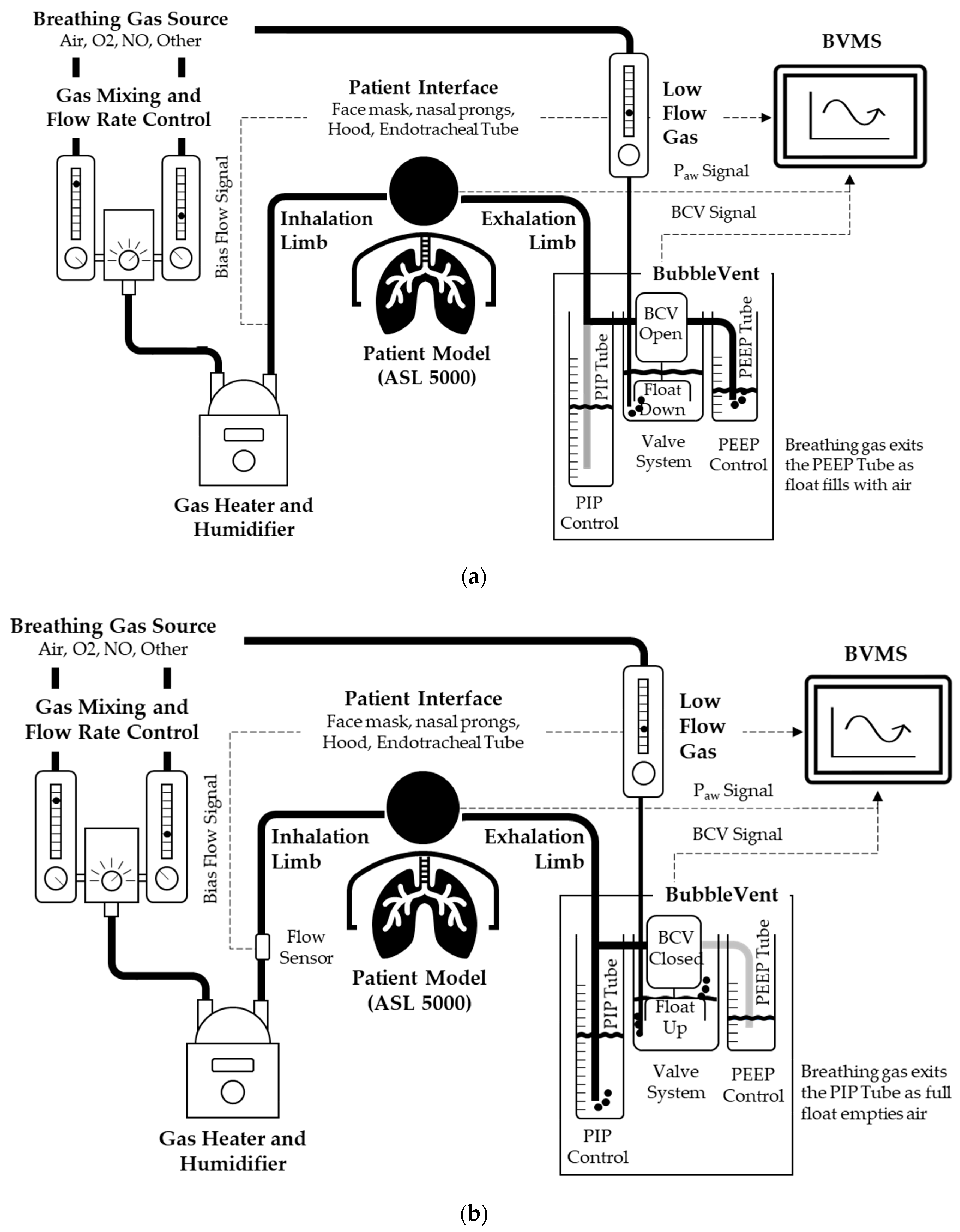
2.1. Description and Operation of the BubbleVent
2.1.1. Airway Pressure Control
2.1.2. Control of PIP and PEEP Delivery
2.1.3. Control of PIP and PEEP Timing
2.1.4. Noninvasive Monitoring with Sequoia
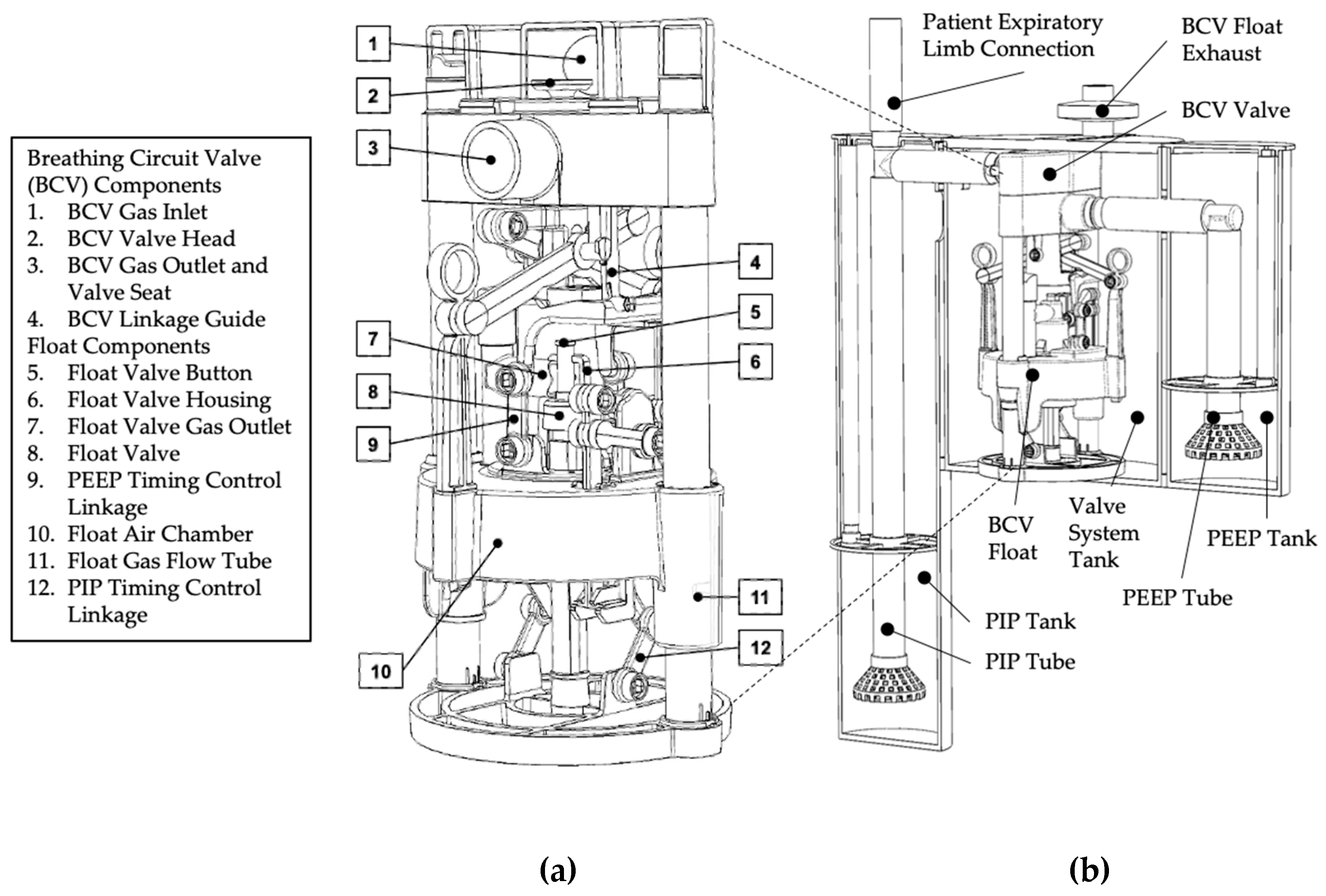
2.2. BubbleVent Manufacturing
2.2.1. Valve System
2.2.2. Water Tanks
2.3. In Vitro Testing of BubbleVent
2.3.1. Experimental Setup
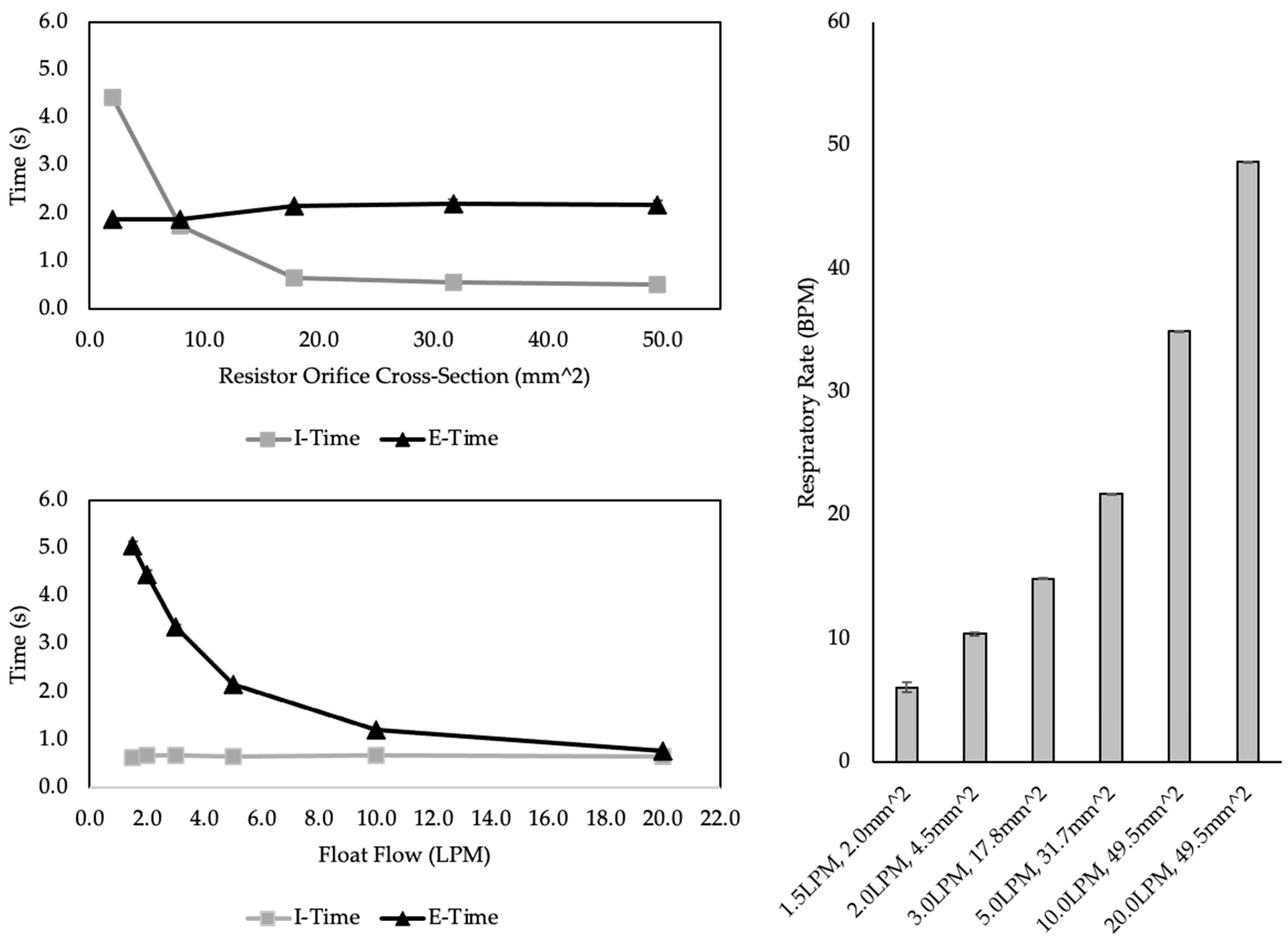
2.3.2. Test 1: Timing Control
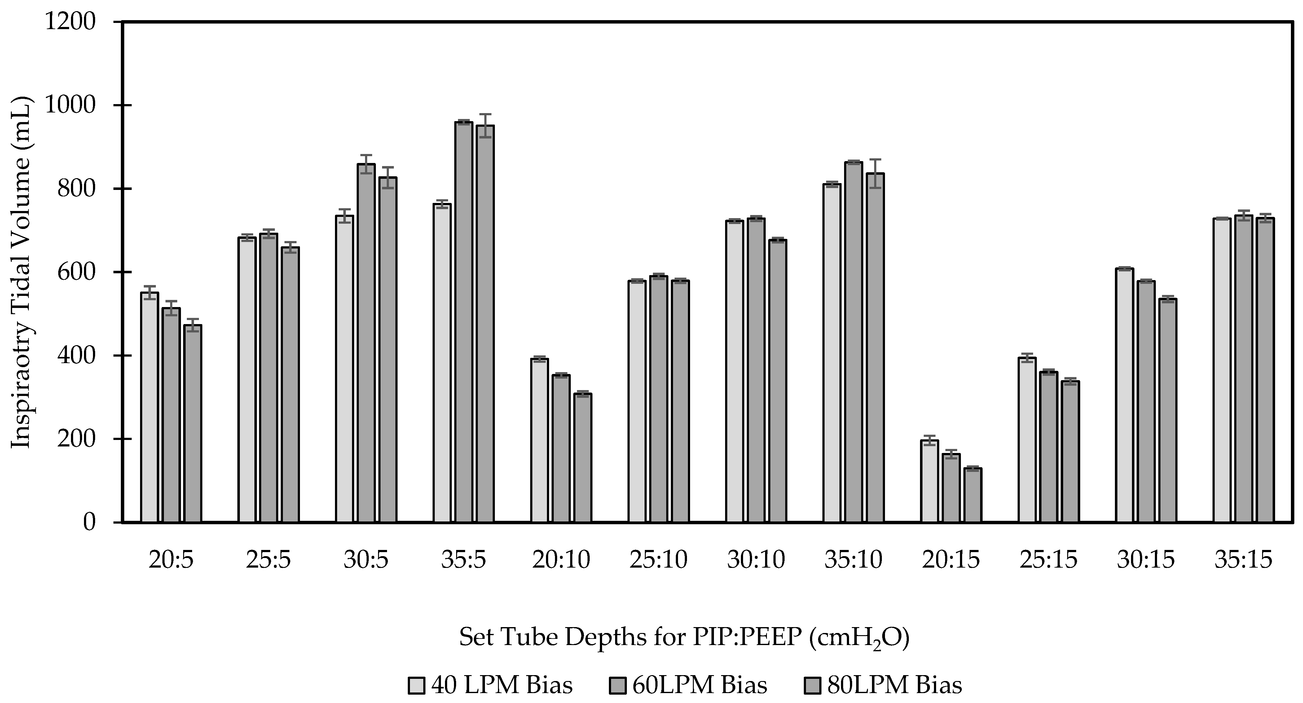
2.3.3. Pressure Control and Volume Delivery
2.3.4. Comparison with a Critical Care Ventilator
3. Results
3.1. Test 1 Results
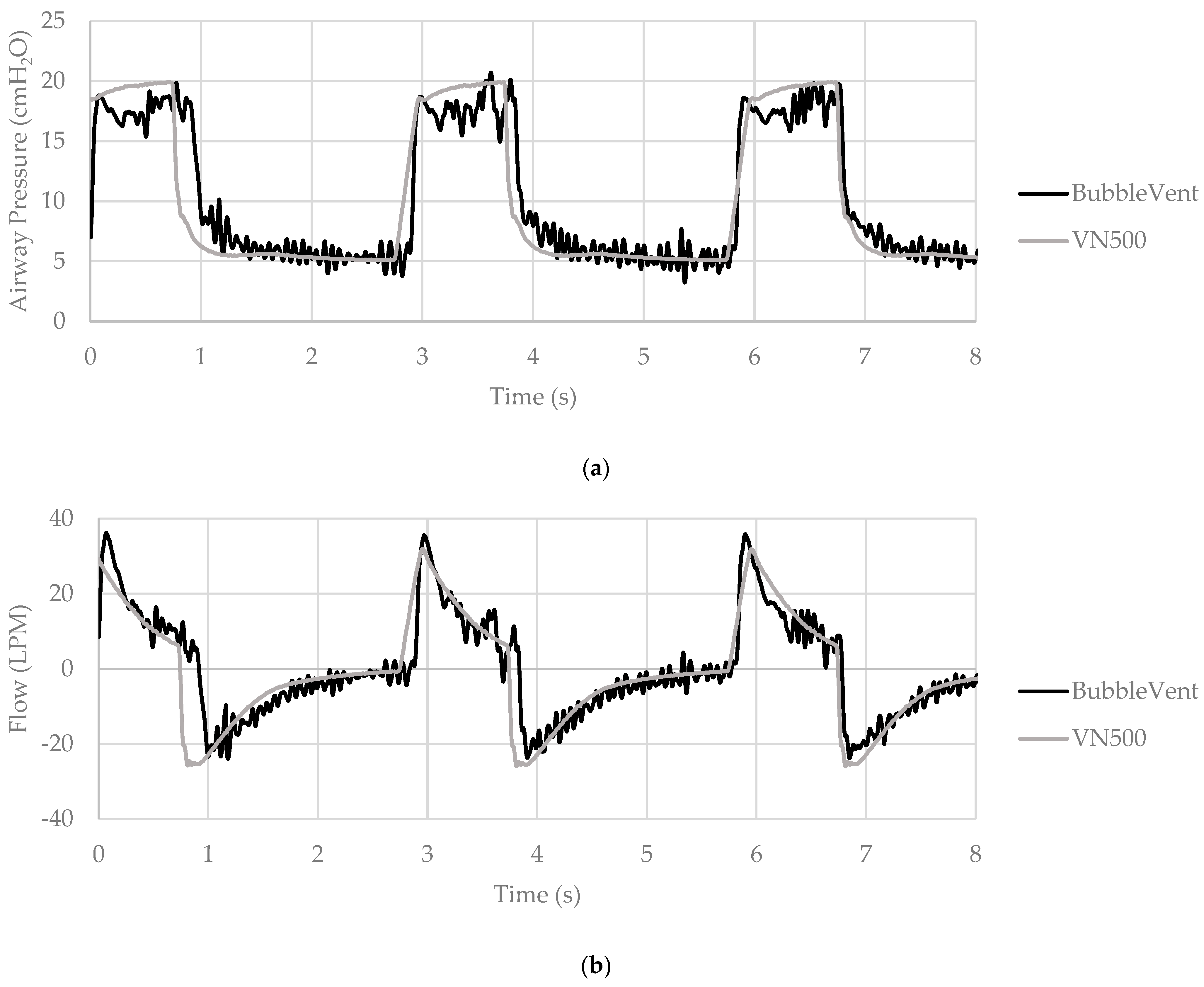
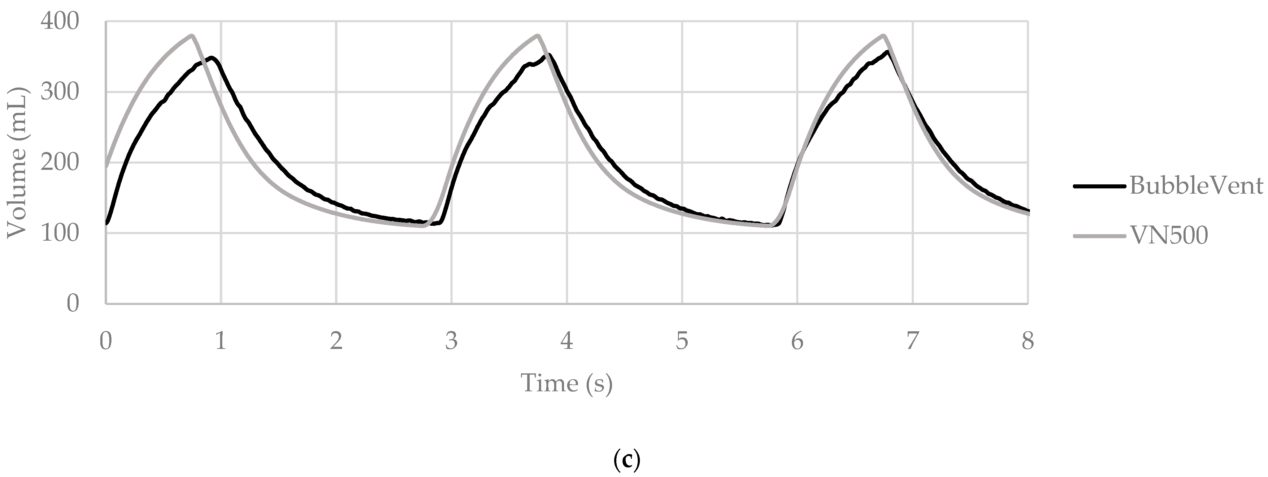
3.2. Test 2 Results
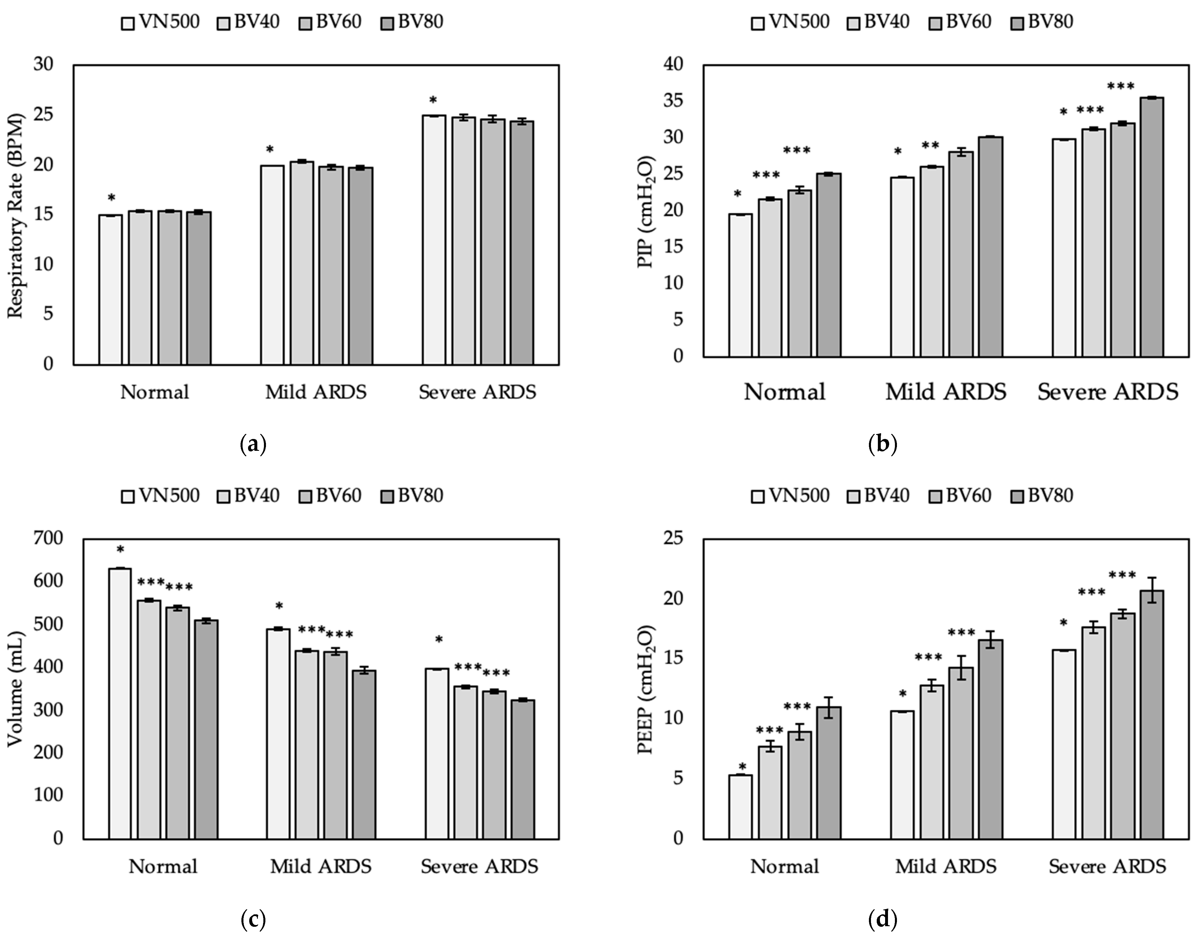
3.3. Test 3 Results
4. Discussion
4.1. Design Risks and Limitations
4.2. Study Limitations
5. Conclusions
Supplementary Materials
Author Contributions
Funding
Institutional Review Board Statement
Informed Consent Statement
Data Availability Statement
Acknowledgments
Conflicts of Interest
References
- John Hopkins Coronavirus Resource Center. COVID-19 Dashboard. Available online: https://coronavirus.jhu.edu/map.html (accessed on 11 October 2021).
- Gattinoni, L.; Coppola, S.; Cressoni, M.; Busana, M.; Rossi, S.; Chiumello, D. COVID-19 Does Not Lead to a “Typical” Acute Respiratory Distress Syndrome. Am. J. Respir. Crit. Care Med. 2020, 201, 1299–1300. [Google Scholar] [CrossRef] [PubMed] [Green Version]
- Dondorp, A.M.; Hayat, M.; Aryal, D.; Beane, A.; Schultz, M.J. Respiratory Support in COVID-19 Patients, with a Focus on Resource-Limited Settings. Am. J. Trop. Med. Hyg. 2020, 102, 1191–1197. [Google Scholar] [CrossRef] [PubMed]
- Ranney, M.L.; Griffeth, V.; Jha, A.K. Critical Supply Shortages—The Need for Ventilators and Personal Protective Equipment during the COVID-19 Pandemic. N. Engl. J. Med. 2020, 382, e41. [Google Scholar] [CrossRef] [PubMed]
- Agarwal, A.; Basmaji, J.; Muttalib, F.; Granton, D.; Chaudhuri, D.; Chetan, D.; Hu, M.; Fernando, S.M.; Honarmand, K.; Bakaa, L.; et al. High-flow nasal cannula for acute hypoxemic respiratory failure in patients with COVID-19: Systematic reviews of effectiveness and its risks of aerosolization, dispersion, and infection transmission. Can. J. Anaesth. 2020, 67, 1217–1248. [Google Scholar] [CrossRef] [PubMed]
- Radovanovic, D.; Rizzi, M.; Pini, S.; Saad, M.; Chiumello, D.A.; Santus, P. Helmet CPAP to Treat Acute Hypoxemic Respiratory Failure in Patients with COVID-19: A Management Strategy Proposal. J. Clin. Med. 2020, 9, 1191. [Google Scholar] [CrossRef]
- Meara, J.G.; Leather, A.J.; Hagander, L.; Alkire, B.C.; Alonso, N.; Ameh, E.A.; Bickler, S.W.; Conteh, L.; Dare, A.J.; Davies, J.; et al. Global Surgery 2030: Evidence and solutions for achieving health, welfare, and economic development. Lancet 2015, 386, 569–624. [Google Scholar] [CrossRef]
- Pearce, J.M. A review of open source ventilators for COVID-19 and future pandemics [version 2; peer review: 3 approved]. F1000Research 2020, 9, 218. [Google Scholar] [CrossRef]
- Welty, S.E.; Rusin, C.G.; Stanberry, L.I.; Mandy, G.T.; Gest, A.L.; Ford, J.M.; Backes, C.H., Jr.; Richardson, C.P.; Howard, C.R.; Hansen, T.N.; et al. Short term evaluation of respiratory effort by premature infants supported with bubble nasal continuous airway pressure using Seattle-PAP and a standard bubble device. PLoS ONE 2018, 13, e0193807. [Google Scholar] [CrossRef]
- Christou, A.; Ntagios, M.; Hart, A.; Dahiya, R. GlasVent—The rapidly deployable emergency ventilator. Glob. Chall. 2020, 4, 2000046. [Google Scholar] [CrossRef]
- Vasan, A.; Weekes, R.; Connacher, W.; Sieker, J.; Stambaugh, M.; Suresh, P.; Lee, D.E.; Mazzei, W.; Schlaepfer, E.; Vallejos, T.; et al. MADVent: A low-cost ventilator for patients with COVID-19. Med. Devices Sens. 2020, 5, e10106. [Google Scholar] [CrossRef]
- Gino, B.; Wang, Z.; d’Entremont, P.; Renouf, T.S.; Dubrowski, A. Automated Inflating Resuscitator (AIR): Design and Development of a 3D-Printed Ventilator Prototype and Corresponding Simulation Scenario Based on the Management of a Critical COVID-19 Patient. Cureus 2020, 12, e9134. [Google Scholar] [CrossRef] [PubMed]
- Grimshandl, D.; Gerken, M.; Lippi, E.; Tran, B.; Hassan, S.Z.; Becher, J.H.; Jochim, S.; Weidemüller, M.; Föhner, G.; Brucker, S.; et al. The HDvent Emergency Ventilator System. arXiv 2020, arXiv:2012.13005. [Google Scholar]
- Khan, Y.; Fahad, H.M.; Muin, S.; Gopalan, K. A low-cost, helmet-based, non-invasive ventilator for COVID-19. arXiv 2020, arXiv:2005.11008. [Google Scholar]
- Raymond, S.J.; Wesolowski, T.; Baker, S.; Liu, Y.; Edmunds, J.L.; Bustamante, M.J.; Ley, B.; Free, D.; Maharbiz, M.; Van Wert, R.; et al. A low-cost, rapidly scalable, emergency use ventilator for the COVID-19 crisis. medRxiv 2020. [Google Scholar] [CrossRef]
- Cole, J.H.; Hughey, S.B.; Rector, C.H.; Booth, G.J. A novel low-cost ventilator for use in a worldwide pandemic: The Portsmouth ventilator. Crit. Care Explor. 2020, 2, e0292. [Google Scholar] [CrossRef]
- LaChance, J.; Zajdel, T.J.; Schottdorf, M.; Saunders, J.; Dvali, S.; Seirup, L.; Marshall, C.; Notterman, D.A.; Cohen, D.J. PVP1—The People’s Ventilator Project: A fully open, low-cost, pressure-controlled ventilator. medRxiv 2020. [Google Scholar] [CrossRef]
- Poli, J.A.; Richardson, C.P.; DiBlasi, R.M. Volume Oscillations Delivered to a Lung Model Using 4 Different Bubble CPAP Systems. Respir. Care 2015, 60, 371–381. [Google Scholar] [CrossRef] [Green Version]
- Diblasi, R.M.; Zignego, J.C.; Tang, D.M.; Hildebrandt, J.; Smith, C.V.; Hansen, T.N.; Richardson, C.P. Noninvasive respiratory support of juvenile rabbits by high-amplitude bubble continuous positive airway pressure. Pediatr. Res. 2010, 67, 624–629. [Google Scholar] [CrossRef] [Green Version]
- Wung, J.T.; Driscoll, J.M., Jr.; Epstein, R.A.; Hyman, A.I. A new device for CPAP by nasal route. Crit. Care Med. 1975, 3, 76–78. [Google Scholar] [CrossRef]
- Diblasi, R.M.; Zignego, J.C.; Smith, C.V.; Hansen, T.N.; Richardson, C.P. Effective gas exchange in paralyzed juvenile rabbits using simple, inexpensive respiratory support devices. Pediatr. Res. 2010, 68, 526–530. [Google Scholar] [CrossRef] [Green Version]
- John, S.C.; Barnett, J.D.; Habben, N.D.; Le, H.T.; Cheng, E.; John, S.P.; Gustafson, P.A. Development and Testing of a Bubble Bi-Level Positive Airway Pressure System. Respir. Care 2017, 62, 1131–1136. [Google Scholar] [CrossRef] [PubMed] [Green Version]
- John, S.C.; Mohammed, A.; Church, J.T.; John, A.V.; Perkins, E.M.; McLeod, J.S.; Carr, B.D.; Smith, S.; Barnett, J.H.; Gustafson, P.A.; et al. Bubble bilevel ventilation facilitates gas exchange in anesthetized rabbits. Pediatr. Res. 2021, 89, 622–627. [Google Scholar] [CrossRef] [PubMed]
- John, S.C.; John, A.V.; Moss, A.W.; Gustafson, P.A.; Fernando-Silva, L.; John, S.P. Bench Testing of a Bubble Noninvasive Ventilation Device in an Infant Lung Simulator. Respir. Care 2020, 65, 1339–1345. [Google Scholar] [CrossRef] [PubMed]
- Milliner, B.H.; Bentley, S.; DuCanto, J. A pilot study of improvised CPAP (iCPAP) via face mask for the treatment of adult respiratory distress in low-resource settings. Int. J. Emerg. Med. 2019, 12, 7. [Google Scholar] [CrossRef] [Green Version]
- Pillow, J.J.; Hillman, N.; Moss, T.J.; Polglase, G.; Bold, G.; Beaumont, C.; Ikegami, M.; Jobe, A.H. Bubble continuous positive airway pressure enhances lung volume and gas exchange in preterm lambs. Am. J. Respir. Crit. Care Med. 2007, 176, 63–69. [Google Scholar] [CrossRef]
- Arnal, J.M.; Garnero, A.; Saoli, M.; Chatburn, R.L. Parameters for Simulation of Adult Subjects During Mechanical Ventilation. Respir. Care 2018, 63, 158–168. [Google Scholar] [CrossRef] [Green Version]
- Ntoumenopoulos, G.; Shannon, H.; Main, E. Do commonly used ventilator settings for mechanically ventilated adults have the potential to embed secretions or promote clearance? Respir. Care 2011, 56, 1887–1892. [Google Scholar] [CrossRef] [Green Version]
- Albert, R.K. Constant Tidal Volume Ventilation and Surfactant Dysfunction: An Overlooked Cause of Ventilator-Induced Lung Injury. Am. J. Respir. Crit. Care Med. 2021, 205, 152–160. [Google Scholar] [CrossRef]


| Pressure State | BCV State | Valve Head State | Float State |
|---|---|---|---|
| PIP | Closed | Down | Up |
| PEEP | Open | Up | Down |
| Parameter | No ARDS | Mild ARDS | Severe ARDS |
| Lung Compliance (mL/cmH2O) | 55 | 45 | 35 |
| Inspiratory Resistance (cmH2O/L/min) | 12 | 12 | 12 |
| Expiratory Resistance (cmH2O/L/min) | 12 | 13 | 14 |
| Setting | No ARDS | Mild ARDS | Severe ARDS |
| Set PEEP (cmH2O) | 5 | 10 | 15 |
| Set PIP (cmH2O) | 20 | 25 | 30 |
| Set TI (s) | 1.3 | 1.0 | 0.8 |
| Set RR (BPM) | 15 | 20 | 25 |
| Set TI (s) | Set RR (BPM) | BVMS TI (s) | Measured TI (s) | TI Percent Error (%) | BVMS RR (BPM) | Measured RR (BPM) | RR Percent Error (%) |
|---|---|---|---|---|---|---|---|
| 0.5 | 15.0 | 0.56 ± 0.01 | 0.46 ± 0.05 | 22.0 | 14.99 ± 0.08 | 14.9 ± 0.08 | 0.6 |
| 0.5 | 20.0 | 0.55 ± 0.05 | 0.56 ± 0.03 | −1.6 | 19.93 ± 0.33 | 19.52 ± 0.05 | 2.1 |
| 0.5 | 30.0 | 0.53 ± 0.04 | 0.5 ± 0.01 | 5.4 | 30.51 ± 0.39 | 30.66 ± 0.03 | −0.5 |
| 0.5 | 40.0 | 0.53 ± 0.04 | 0.48 ± 0.01 | 11.2 | 40.38 ± 1.26 | 40.13 ± 0.02 | 0.6 |
| 0.5 | 50.0 | 0.58 ± 0.01 | 0.43 ± 0.01 | 35.3 | 50.27 ± 0.64 | 50.28 ± 0.01 | 0.0 |
| 0.8 | 8.0 | 0.79 ± 0.03 | 0.73 ± 0.08 | 8.8 | 8.14 ± 0.23 | 7.88 ± 0.25 | 3.3 |
| 0.8 | 16.0 | 0.79 ± 0.01 | 0.66 ± 0.01 | 20.6 | 16.08 ± 0.18 | 16.27 ± 0.04 | −1.2 |
| 0.8 | 24.0 | 0.84 ± 0.04 | 0.79 ± 0.02 | 6.0 | 24.01 ± 0.48 | 24.19 ± 0.02 | −0.7 |
| 1.0 | 5.0 | 0.99 ± 0.02 | 0.88 ± 0.03 | 12.0 | 5.26 ± 0.23 | 5.3 ± 0.12 | −0.9 |
| 1.0 | 10.0 | 0.99 ± 0.01 | 0.86 ± 0.03 | 15.9 | 10.06 ± 0.14 | 10.16 ± 0.05 | −1.0 |
| 1.0 | 15.0 | 0.96 ± 0.05 | 0.88 ± 0.01 | 9.2 | 14.99 ± 0.25 | 14.84 ± 0.04 | 1.0 |
| 1.0 | 20.0 | 1.02 ± 0.07 | 0.9 ± 0.05 | 13.4 | 19.78 ± 0.33 | 19.5 ± 0.08 | 1.5 |
| 1.0 | 30.0 | 1.08 ± 0.02 | 0.92 ± 0.02 | 17.4 | 30.55 ± 0.65 | 30.74 ± 0.03 | −0.6 |
| 1.5 | 10.0 | 1.55 ± 0.08 | 1.39 ± 0.09 | 11.6 | 9.43 ± 0.65 | 10.01 ± 0.15 | −5.7 |
| 1.5 | 20.0 | 1.59 ± 0.03 | 1.49 ± 0.04 | 6.6 | 21.01 ± 0.17 | 20.96 ± 0.04 | 0.2 |
| 1.5 | 30.0 | 1.46 ± 0.04 | 1.2 ± 0.02 | 21.0 | 30.3 ± 0.66 | 29.97 ± 0.02 | 1.1 |
| 2.0 | 20.0 | 1.97 ± 0.04 | 1.76 ± 0.05 | 11.8 | 20.63 ± 0.35 | 20.58 ± 0.05 | 0.2 |
| 3.0 | 15.0 | 2.97 ± 0.04 | 2.88 ± 0.15 | 3.3 | 14.77 ± 0.18 | 14.6 ± 0.15 | 1.2 |
| 4.0 | 10.0 | 3.92 ± 0.15 | 4.2 ± 0.34 | −6.7 | 10.21 ± 0.31 | 9.39 ± 0.42 | 8.7 |
| Set PEEP (cmH2O) | Set PIP (cmH2O) | Bias Flow (LPM) | Measured PIP (cmH2O) | PIP Percent Error (%) | Measured PEEP (cmH2O) | PEEP Percent Error (%) |
|---|---|---|---|---|---|---|
| 5 | 20 | 40 | 21.59 ± 0.25 | 7.94 | 7.96 ± 0.30 | 59.15 |
| 5 | 20 | 60 | 23.37 ± 0.26 | 16.83 | 9.90 ± 0.88 | 97.93 |
| 5 | 20 | 80 | 26.43 ± 0.25 | 32.17 | 12.39 ± 0.77 | 147.78 |
| 5 | 25 | 40 | 24.93 ± 0.16 | −0.28 | 7.82 ± 0.63 | 56.32 |
| 5 | 25 | 60 | 27.32 ± 0.39 | 9.27 | 9.26 ± 0.53 | 85.16 |
| 5 | 25 | 80 | 29.23 ± 0.56 | 16.90 | 11.61 ± 0.9 | 132.25 |
| 5 | 30 | 40 | 27.97 ± 0.12 | −6.77 | 8.12 ± 0.53 | 62.50 |
| 5 | 30 | 60 | 30.67 ± 0.47 | 2.24 | 9.52 ± 0.78 | 90.38 |
| 5 | 30 | 80 | 32.64 ± 0.51 | 8.80 | 12.28 ± 0.99 | 145.56 |
| 5 | 35 | 40 | 28.28 ± 0.12 | −19.19 | 7.72 ± 0.55 | 54.30 |
| 5 | 35 | 60 | 34.09 ± 0.08 | −2.61 | 9.46 ± 0.77 | 89.28 |
| 5 | 35 | 80 | 35.65 ± 0.54 | 1.84 | 11.95 ± 0.67 | 139.06 |
| 10 | 20 | 40 | 22.74 ± 0.30 | 13.71 | 12.66 ± 0.41 | 26.57 |
| 10 | 20 | 60 | 25.91 ± 0.12 | 29.53 | 14.43 ± 1.02 | 44.33 |
| 10 | 20 | 80 | 30.10 ± 0.13 | 50.48 | 16.92 ± 0.88 | 69.20 |
| 10 | 25 | 40 | 26.93 ± 0.43 | 7.74 | 12.96 ± 0.61 | 29.64 |
| 10 | 25 | 60 | 28.56 ± 0.49 | 14.23 | 14.33 ± 0.82 | 43.31 |
| 10 | 25 | 80 | 26.84 ± 0.42 | 7.37 | 12.75 ± 0.25 | 27.54 |
| 10 | 30 | 40 | 30.23 ± 0.13 | 0.76 | 12.95 ± 0.43 | 29.48 |
| 10 | 30 | 60 | 32.61 ± 0.35 | 8.69 | 14.45 ± 0.68 | 44.47 |
| 10 | 30 | 80 | 33.92 ± 0.51 | 13.06 | 16.84 ± 0.43 | 68.44 |
| 10 | 35 | 40 | 34.03 ± 0.03 | −2.78 | 12.84 ± 0.55 | 28.38 |
| 10 | 35 | 60 | 35.75 ± 0.31 | 2.14 | 15.07 ± 0.28 | 50.74 |
| 10 | 35 | 80 | 36.62 ± 0.78 | 4.63 | 16.58 ± 1.15 | 65.78 |
| 15 | 20 | 40 | 24.62 ± 0.20 | 23.10 | 17.71 ± 0.53 | 18.06 |
| 15 | 20 | 60 | 28.77 ± 0.44 | 43.83 | 19.41 ± 1.17 | 29.43 |
| 15 | 20 | 80 | 31.49 ± 0.84 | 57.44 | 20.67 ± 0.83 | 37.80 |
| 15 | 25 | 40 | 27.35 ± 0.28 | 9.38 | 17.20 ± 0.52 | 14.67 |
| 15 | 25 | 60 | 30.40 ± 0.16 | 21.61 | 18.92 ± 0.71 | 26.10 |
| 15 | 25 | 80 | 34.33 ± 0.26 | 37.30 | 19.98 ± 0.58 | 33.23 |
| 15 | 30 | 40 | 31.02 ± 0.09 | 3.40 | 16.57 ± 0.46 | 10.50 |
| 15 | 30 | 60 | 33.32 ± 0.61 | 11.08 | 18.77 ± 0.89 | 25.16 |
| 15 | 30 | 80 | 34.45 ± 0.38 | 14.83 | 20.95 ± 0.52 | 39.68 |
| 15 | 35 | 40 | 35.22 ± 0.10 | 0.63 | 17.45 ± 0.63 | 16.33 |
| 15 | 35 | 60 | 37.23 ± 0.64 | 6.38 | 19.36 ± 0.71 | 29.07 |
| 15 | 35 | 80 | 38.90 ± 0.67 | 11.16 | 20.91 ± 0.96 | 39.43 |
Publisher’s Note: MDPI stays neutral with regard to jurisdictional claims in published maps and institutional affiliations. |
© 2022 by the authors. Licensee MDPI, Basel, Switzerland. This article is an open access article distributed under the terms and conditions of the Creative Commons Attribution (CC BY) license (https://creativecommons.org/licenses/by/4.0/).
Share and Cite
Poli, J.A.; Howard, C.; Garcia, A.J., III; Remboski, D.; Littlewood, P.B.; Kress, J.P.; Kasthuri, N.; Comai, A.; Soni, K.; Kennedy, P.; et al. Performance Characteristics of a Novel 3D-Printed Bubble Intermittent Mandatory Ventilator (B-IMV) for Adult Pulmonary Support. Bioengineering 2022, 9, 151. https://doi.org/10.3390/bioengineering9040151
Poli JA, Howard C, Garcia AJ III, Remboski D, Littlewood PB, Kress JP, Kasthuri N, Comai A, Soni K, Kennedy P, et al. Performance Characteristics of a Novel 3D-Printed Bubble Intermittent Mandatory Ventilator (B-IMV) for Adult Pulmonary Support. Bioengineering. 2022; 9(4):151. https://doi.org/10.3390/bioengineering9040151
Chicago/Turabian StylePoli, Jonathan A., Christopher Howard, Alfredo J. Garcia, III, Don Remboski, Peter B. Littlewood, John P. Kress, Narayanan Kasthuri, Alia Comai, Kiran Soni, Philip Kennedy, and et al. 2022. "Performance Characteristics of a Novel 3D-Printed Bubble Intermittent Mandatory Ventilator (B-IMV) for Adult Pulmonary Support" Bioengineering 9, no. 4: 151. https://doi.org/10.3390/bioengineering9040151