
Modeling and Analysis of Foot Function in Human Gait Using a Two-Degrees-of-Freedom Inverted Pendulum Model with an Arced Foot

 ,
,
Abstract
:
1. Introduction
2. Methods
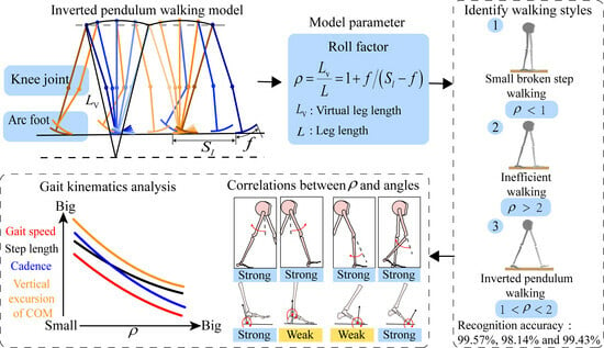
2.1. Gait Model
2.2. Gait Parameters
2.3. Gait Recognition
3. Experiment
3.1. Subjects
3.2. Protocol
3.2.1. Treadmill Test for Model Verification
3.2.2. Level Walk Test for Gait Recognition with the 2-DOF Model
3.3. Data Collection and Kinematic Parameter Calculation
3.4. Statistical Analysis
4. Results
4.1. Gait Analysis
4.2. Gait Recognition
5. Discussion
6. Conclusions
Author Contributions
Funding
Institutional Review Board Statement
Informed Consent Statement
Data Availability Statement
Acknowledgments
Conflicts of Interest
References
- Alves, F.; Cruz, S.; Ribeiro, A.; Silva, A.B.; Martins, J.; Cunha, I. Walkability Index for Elderly Health: A Proposal. Sustainability 2020, 12, 7360. [Google Scholar] [CrossRef]
- Chan, E.T.H.; Li, T.E.; Schwanen, T. People and Their Walking Environments: An Exploratory Study of Meanings, Place and Times. Int. J. Sustain. Transp. 2021, 15, 718–729. [Google Scholar] [CrossRef]
- Lee, I.M.; Buchner, D.M. The Importance of Walking to Public Health. Med. Sci. Sport. Exerc. 2008, 40, S512–S518. [Google Scholar] [CrossRef] [PubMed]
- McDermott, M.M.; Spring, B.; Tian, L. Effect of Low-Intensity vs High-Intensity Home-Based Walking Exercise on Walk Distance in Patients with Peripheral Artery Disease: The LITE Randomized Clinical Trial. JAMA 2021, 325, 1266–1276. [Google Scholar] [CrossRef]
- Gothe, N.P.; Ehlers, D.K.; Salerno, E.A.; Fanning, J.; Kramer, A.F.; McAuley, E. Physical Activity, Sleep and Quality of Life in Older Adults: Influence of Physical, Mental and Social Well-being. Behav. Sleep Med. 2019, 18, 797–808. [Google Scholar] [CrossRef]
- Xiong, J.; Ye, M.; Wang, L.; Zheng, G. Effects of Physical Exercise on Executive Function in Cognitively Healthy Older Adults: A Systematic Review and Meta-Analysis of Randomized Controlled Trials: Physical Exercise for Executive Function. Int. J. Nurs. Stud. 2021, 114, 103810. [Google Scholar] [CrossRef]
- Kalita, B.; Narayan, J.; Dwivedy, S.K. Development of Active Lower Limb Robotic-Based Orthosis and Exoskeleton Devices: A Systematic Review. Int. J. Soc. Robot. 2021, 13, 775–793. [Google Scholar] [CrossRef]
- Plaza, A.; Hernandez, M.; Puyuelo, G. Lower-Limb Medical and Rehabilitation Exoskeletons: A Review of the Current Designs. IEEE Rev. Biomed. Eng. 2021, 16, 278–291. [Google Scholar] [CrossRef] [PubMed]
- Rodríguez, F.A.; Lobo, P.J.; Font, L.J.M. Systematic Review on Wearable Lower-Limb Exoskeletons for Gait Training in Neuromuscular Impairments. J. Neuroeng. Rehabil. 2021, 18, 22. [Google Scholar] [CrossRef] [PubMed]
- Miller, T.M.; Natividad, R.F.; Lim, D.Y.L. A Wearable Soft Robotic Exoskeleton for Hip Flexion Rehabilitation. Front. Robot. AI 2022, 9, 835237. [Google Scholar] [CrossRef]
- Kapsalyamov, A.; Jamwal, P.K.; Hussain, S.; Ghayesh, M.H. State of the Art Lower Limb Robotic Exoskeletons for Elderly Assistance. IEEE Access 2019, 7, 95075–95086. [Google Scholar] [CrossRef]
- Wang, T.; Zhang, B.; Liu, C.; Liu, T.; Han, Y.; Wang, S.; Ferreira, J.P.; Dong, W.; Zhang, X. A Review on the Rehabilitation Exo-skeletons for the Lower Limbs of the Elderly and the Disabled. Electronics 2022, 11, 388. [Google Scholar] [CrossRef]
- Viteckova, S.; Kutilek, P.; Jirina, M. Wearable Lower Limb Robotics: A review. Biocybern. Biomed. Eng. 2013, 33, 96–105. [Google Scholar] [CrossRef]
- Zhou, J.; Yang, S.; Xue, Q. Lower Limb Rehabilitation Exoskeleton Robot: A review. Adv. Mech. Eng. 2021, 13, 16878140211011862. [Google Scholar] [CrossRef]
- Vidal, A.P.; Morales, J.R.; Torres, G.O.; Vázquez, F.S.; Rojas, A.C.; Mendoza, J.B.; Cerda, J.R. Soft Exoskeletons: Development, Requirements, and Challenges of the Last Decade. Actuators 2021, 10, 166. [Google Scholar] [CrossRef]
- Baud, R.; Manzoori, A.R.; Ijspeert, A.; Bouri, M. Review of Control Strategies for Lower-Limb Exoskeletons to Assist Gait. J. Neuroeng. Rehabil. 2021, 18, 119. [Google Scholar] [CrossRef]
- Chinmilli, P.; Redkar, S.; Zhang, W. A Review on Wearable Inertial Tracking Based Human Gait Analysis and Control Strategies of Lower-Limb Exoskeletons. Int. Robot. Autom. J. 2017, 3, 398–415. [Google Scholar]
- Kolaghassi, R.; Al-Hares, M.K.; Sirlantzis, K. Systematic Review of Intelligent Algorithms in Gait Analysis and Prediction for Lower Limb Robotic systems. IEEE Access 2021, 9, 113788–113812. [Google Scholar] [CrossRef]
- Xiang, Y.J.; Arora, J.S.; Karim, A.M. Physics-Based Modeling and Simulation of Human Walking: A Review of Optimization-Based and Other Approaches. Struct. Multidisc. Optim. 2010, 42, 1–23. [Google Scholar] [CrossRef]
- Rajagopal, A.; Dembia, C.; Demers, M.; Delp, D.; Hicks, J.; Delp, S. Full-Body Musculoskeletal Model for Muscle-Driven Simulation of Human Gait. IEEE Trans. Biomed. Eng. 2016, 63, 2068–2079. [Google Scholar] [CrossRef]
- Sylvester, A.D.; Lautzenheiser, S.G.; Kramer, P.A. A Review of Musculoskeletal Modelling of Human Locomotion. Interface Focus 2021, 11, 20200060. [Google Scholar] [CrossRef] [PubMed]
- Grabke, E.P.; Masani, K.; Andrysek, J. Lower Limb Assistive Device Design Optimization Using Musculoskeletal Modeling: A Review. J. Med. Devices 2019, 13, 040801. [Google Scholar] [CrossRef]
- Yu, J.; Zhang, S.; Wang, A.; Li, W.; Song, L. Musculoskeletal modeling and humanoid control of robots based on human gait data. PeerJ Comput. Sci. 2021, 7, e657. [Google Scholar] [CrossRef] [PubMed]
- Schiehlen, W. Human Walking Dynamics: Modeling, Identification and Control. In Proceedings of the MATEC Web of Conferences, CSNDD 2014-International Conference on Structural Nonlinear Dynamics and Diagnosis, Agadir, Morocco, 19–21 May 2014; Volume 16, p. 05008. [Google Scholar]
- Sun, C.; Wu, Q.; Zhang, K.; Li, H. A Simulation Method for Walking Gait of Human Daily Activity Oriented on Intelligent Artificial Limbs and Exoskeleton. In Proceedings of the 5th Annual IEEE International Conference on Cyber Technology in Automation 2015, Control and Intelligent Systems, Shenyang, China, 6–10 June 2015. [Google Scholar]
- Cavagna, G.A.; Heglund, N.C.; Taylor, C.R. Mechanical Work in Terrestrial Locomotion: Two Basic Mechanisms for Minimizing Energy Expenditure. Am. J. Physiol. 1977, 235, R243–R261. [Google Scholar] [CrossRef]
- Buczek, F.L.; Cooney, K.M.; Walker, M.R.; Rainbow, M.J.; Concha, M.C.; Sanders, J.O. Performance of an Inverted Pendulum Model Directly Applied to Normal Human Gait. Clin. Bio. 2006, 21, 288–296. [Google Scholar] [CrossRef]
- Kuo, A.D. The Six Determinants of Gait and the Inverted Pendulum Analogy: A Dynamic Walking Perspective. Hum. Mov. Sci. 2007, 26, 617–656. [Google Scholar] [CrossRef]
- Martin, A.E.; Schmiedeler, J.P. Predicting Human Walking Gaits with a Simple Planar Model. J. Biomech. 2014, 47, 1416–1421. [Google Scholar] [CrossRef]
- McGrath, M.; Howard, D.; Baker, R. A Forward Dynamic Modelling Investigation of Cause-and-Effect Relationships in Single Support Phase of Human Walking. Comput. Math. Methods Med. 2015, 2015, 383705. [Google Scholar] [CrossRef]
- Hong, H.; Kim, S.; Kim, C.; Lee, S.; Park, S. Spring-Like Gait Mechanics Observed During Walking in Both Young and Older Adults. J. Biomech. 2013, 46, 77–82. [Google Scholar] [CrossRef]
- Koolen, T.; Boer, T.D.; Rebula, J.; Goswami, A.; Pratt, J. Capturability-Based Analysis and Control of Legged Locomotion, Part 1: Theory and Application to Three Simple Gait Models. Int. J. Robot. Res. 2012, 31, 1094–1113. [Google Scholar] [CrossRef]
- Shahbazi, M.; Babuska, R.; Lopes, G.A.D. Unified Modeling and Control of Walking and Running on the Spring-Loaded Inverted Pendulum. IEEE Trans. Robot. 2016, 32, 1178–1195. [Google Scholar] [CrossRef]
- Srinivasan, M. Fifteen Observations on the Structure of Energy-Minimizing Gaits in Many Simple Biped Models. J. R. Soc. Interface 2010, 8, 74–98. [Google Scholar] [CrossRef] [PubMed]
- Lim, H.; Park, S. Kinematics of Lower Limbs During Walking Are Emulated by Springy Walking Model with a Compliantly Connected, Off-Centered Curvy Foot. J. Biomech. 2018, 71, 119–126. [Google Scholar] [CrossRef]
- Lim, H.; Park, S. A Bipedal Compliant Walking Model Generates Periodic Gait Cycles with Realistic Swing Dynamics. J. Biomech. 2019, 91, 79–84. [Google Scholar] [CrossRef]
- Gard, S.A.; Childress, D.S. What Determines the Vertical Displacement of the Body During Normal Walking. J. Prosthet. Orthot. 2001, 13, 64–67. [Google Scholar] [CrossRef]
- Faraji, S.; Ijspeert, A.J. 3LP: A Linear 3D-Walking Model Including Torso and Swing Dynamics. Int. J. Robot. Res. 2017, 36, 436–455. [Google Scholar] [CrossRef]
- Kuo, A.D.; Donelan, J.M. Dynamic Principles of Gait and Their Clinical Implications. Phys. Ther. 2010, 90, 157–174. [Google Scholar] [CrossRef]
- Lin, B.; Zhang, Q.; Fan, F.; Shen, S. A damped bipedal inverted pendulum for human–structure interaction analysis. Appl. Math. Model. 2020, 87, 606–624. [Google Scholar] [CrossRef]
- Yang, H.; Wu, B.; Li, J.; Bao, Y.; Xu, G. A Spring-Loaded Inverted Pendulum Model for Analysis of Human-Structure Interaction on Vibrating Surfaces. J. Sound Vib. 2022, 522, 116727. [Google Scholar] [CrossRef]
- Lin, B.; Zivanovic, S.; Zhang, Q.; Fan, F. Implementation of Damped Bipedal Inverted Pendulum Model of Pedestrian into FE Environment for Prediction of Vertical Structural Vibration. Structures 2023, 48, 523–532. [Google Scholar] [CrossRef]
- Zhu, A.; Shen, Z.; Shen, H.; Wu, H.; Zhang, X. Design of a Passive Weight-Support Exoskeleton of Human-Machine Multi-Link. In Proceedings of the 2018 15th International Conference on Ubiquitous Robots (UR), Honolulu, HI, USA, 26–30 June 2018; IEEE: Piscatvey, NJ, USA, 2018; pp. 296–301. [Google Scholar]
- Hanavan, E.P. A Mathematical Model of the Human Body; Technical Report Amrl.; Aerospace Medical Research Laboratories, Aerospace Medical Division, Air Force Systems Command: Dayton, OH, USA, 1964; pp. 64–102. [Google Scholar]
- Hurmuzlu, Y.; Genot, F.; Brogliato, B. Modeling, Stability and Control of Biped Robots a General Framework. Automatica 2004, 40, 1647–1664. [Google Scholar] [CrossRef]
- Ishigaki, T.; Yamamoto, K. Dynamics Computation of a Hybrid Multi-Link Humanoid Robot Intergrating Rigid and Soft Bodies. In Proceedings of the 2021 IEEE/RSJ International Conference on Intelligent Robots and Systems (IROS), Prague, Czech Republic, 27 September–1 October 2021; pp. 2816–2821. [Google Scholar]
- Borisov, A.V.; Kaspirovich, I.E.; Mukharlyamov, R.G. On Mathematical Modeling of the Dynamics of Multilink Systems and Exoskeletons. J. Comput. Sys. Sci. Int. 2021, 60, 827–841. [Google Scholar] [CrossRef]
- Usherwood, J.R. The Collisional Geometry of Economical Walking Predicts Human Leg and Foot Segment Proportions. J. R. Soc. Interface 2023, 20, 20220800. [Google Scholar] [CrossRef] [PubMed]
- Farris, D.J.; Kelly, L.A.; Cresswell, A.G. The Functional Importance of Human Foot Muscles for Bipedal Locomotion. Proc. Natl. Acad. Sci. USA 2019, 116, 1645–1650. [Google Scholar] [CrossRef]
- Perry, J.; Burnfield, J.M. Gait Analysis: Normal and Pathological Function, 2nd ed.; SLACK Incorporated: Thorofare, NJ, USA, 2010. [Google Scholar]
- Jeong, B.; Ko, C.Y.; Chang, Y.; Ryu, J.; Kim, G. Comparison of Segmental Analysis and Sacral Marker Methods for Determining the Center of Mass During Level and Slope Walking. Gait Posture 2018, 62, 333–341. [Google Scholar] [CrossRef]
- Vicon Documentation. Available online: https://docs.vicon.com/display/Nexus25/Plug-in+Gait+kinematic+variables (accessed on 20 March 2020).
- Pfister, A.; West, A.M.; Bronner, S. Comparative Abilities of Microsoft Kinect and Vicon 3D Motion Capture for Gait Analysis. J. Med. Eng. Technol. 2014, 38, 274–280. [Google Scholar] [CrossRef]
- Van, D.B.T. Practical Guide to Data Smoothing and Filtering. 1996, pp. 1–6. Available online: http://isbweb.org/software/sigproc/bogert/filter.pdf (accessed on 31 October 1996).
- Schwartz, M.H.; Trost, J.P.; Wervey, R.A. Measurement and Management of Errors in Quantitative Gait Data. Gait Posture 2004, 20, 196–203. [Google Scholar] [CrossRef]
- Wright, C.; Seitz, A.L.; Arnold, B.L. Repeatability of Ankle Joint Kinematic Data at Heel Strike Using the Vicon Plug-In Gait model. Available online: https://www.researchgate.net/publication/268380486 (accessed on 16 January 2011).
- Webber, J.T.; Raichlen, D.A. The Role of Plantigrady and Heel-Strike in the Mechanics and Energetics of Human Walking with Implications for the Evolution of the Human Foot. J. Exp. Biol. 2016, 219, 3729–3737. [Google Scholar] [CrossRef]
- Zhang, J.; Si, Y.; Zhang, Y.; Liu, Y. The Effects of Restricting the Flexion-Extension Motion of the First Metatarsophalangeal Joint on Human Walking Gait. Bio-Med. Mater. Eng. 2014, 24, 2577–2584. [Google Scholar] [CrossRef]
- Khalaj, N.; Vicenzino, B.; Heales, L.J.; Smith, M.D. Is Chronic Ankle Instability Associated with Impaired Muscle Strength? Ankle, Knee and Hip Muscle Strength in Individuals with Chronic Ankle Instability: A Systematic Review with Meta-analysis. Br. J. Sports Med. 2020, 54, 839–847. [Google Scholar] [CrossRef] [PubMed]
- Kim, S.H.; Kwon, O.Y.; Park, K.N.; Jeon, I.C.; Weon, J.H. Lower Extremity Strength and the Range of Motion in Relation to Squat Depth. J. Hum. Kinet. 2015, 45, 59–69. [Google Scholar] [CrossRef]
- Wu, R.; Zhang, Y.; Bai, J.J.; Sun, J.; Bao, Z.J.; Wang, Z. Impact of Lower Limb Muscle Strength on Walking Function Beyond Aging and Diabetes. J. Int. Med. Res. 2020, 48, 1–9. [Google Scholar] [CrossRef]
- Adamczyk, P.G.; Collins, S.H.; Kuo, A.D. The Advantages of a Rolling Foot in Human Walking. J. Exp. Biol. 2006, 209, 3953–3963. [Google Scholar] [CrossRef] [PubMed]
- Kim, J.; Lee, G.; Heimgartner, R.; Revi, D.A.; Karavas, N.; Nathanson, D.; Galiana, I.; Eckert-Erdheim, A.; Murphy, P.; Perry, D.; et al. Reducing the Metabolic Rate of Walking and Running with a Versatile, Portable Exosuit. Science 2019, 365, 668–672. [Google Scholar] [CrossRef] [PubMed]
- Song, Y.; Cen, X.; Zhang, Y. Development and Validation of A Subject-Specific Coupled Model for Foot and Sports Shoe Complex: A Pilot Computational Study. Bioengineering 2022, 9, 553. [Google Scholar] [CrossRef] [PubMed]
- Farzad, M.; Safaeepour, Z.; Nabavi, H. Effect of Different Placement of Heel Rockers on Lower-Limb Joint Biomechanics in Healthy Individuals. J. Am. Podiatr. Med. Assoc. 2018, 108, 231–235. [Google Scholar] [CrossRef]


| Types | Small Broken Step Walking | Inefficient Walking | Inverted Pendulum Walking | |||
|---|---|---|---|---|---|---|
| Subject Number | Accuracy 1 (%) | Error Rate 2 (%) | Accuracy (%) | Error Rate (%) | Accuracy (%) | Error Rate (%) |
| No. 1 | 100 | 0 | 98 | 0 | 100 | 1 |
| No. 2 | 100 | 0 | 100 | 0 | 100 | 0 |
| No. 3 | 99 | 0 | 98 | 0.5 | 100 | 1 |
| No. 4 | 99 | 0 | 100 | 2.5 | 96 | 0 |
| No. 5 | 100 | 0 | 97 | 0 | 100 | 1.5 |
| No. 6 | 99 | 0 | 98 | 0.5 | 100 | 1 |
| No. 7 | 100 | 0 | 96 | 0 | 100 | 2 |
| Average | 99.57 | - | 98.14 | - | 99.43 | - |
Disclaimer/Publisher’s Note: The statements, opinions and data contained in all publications are solely those of the individual author(s) and contributor(s) and not of MDPI and/or the editor(s). MDPI and/or the editor(s) disclaim responsibility for any injury to people or property resulting from any ideas, methods, instructions or products referred to in the content. |
© 2023 by the authors. Licensee MDPI, Basel, Switzerland. This article is an open access article distributed under the terms and conditions of the Creative Commons Attribution (CC BY) license (https://creativecommons.org/licenses/by/4.0/).
Share and Cite
Xiang, Q.; Guo, S.; Wang, J.; Hashimoto, K.; Liu, Y.; Liu, L. Modeling and Analysis of Foot Function in Human Gait Using a Two-Degrees-of-Freedom Inverted Pendulum Model with an Arced Foot. Bioengineering 2023, 10, 1344. https://doi.org/10.3390/bioengineering10121344
Xiang Q, Guo S, Wang J, Hashimoto K, Liu Y, Liu L. Modeling and Analysis of Foot Function in Human Gait Using a Two-Degrees-of-Freedom Inverted Pendulum Model with an Arced Foot. Bioengineering. 2023; 10(12):1344. https://doi.org/10.3390/bioengineering10121344
Chicago/Turabian StyleXiang, Qian, Shijie Guo, Jiaxin Wang, Kazunobu Hashimoto, Yong Liu, and Lei Liu. 2023. "Modeling and Analysis of Foot Function in Human Gait Using a Two-Degrees-of-Freedom Inverted Pendulum Model with an Arced Foot" Bioengineering 10, no. 12: 1344. https://doi.org/10.3390/bioengineering10121344