Article

Equivalent Circuit Model for High-Power Lithium-Ion Batteries under High Current Rates, Wide Temperature Range, and Various State of Charges

Research Group MOBI—Mobility, Logistics and Automotive Technology Research Centre, Vrije Universiteit Brussel, Pleinlaan 2, 1050 Brussels, Belgium
*
Author to whom correspondence should be addressed.
Batteries 2023, 9(2), 101; https://doi.org/10.3390/batteries9020101
Submission received: 23 December 2022 / Revised: 13 January 2023 / Accepted: 27 January 2023 / Published: 1 February 2023
(This article belongs to the Topic Electric Vehicles Energy Management)

Abstract

:
The most employed technique to mimic the behavior of lithium-ion cells to monitor and control them is the equivalent circuit model (ECM). This modeling tool should be precise enough to ensure the system’s reliability. Two significant parameters that affect the accuracy of the ECM are the applied current rate and operating temperature. Without a thorough understating of the influence of these parameters on the ECM, parameter estimation should be carried out manually within the calibration, which is not favorable. In this work, an enhanced ECM was developed for high-power lithium-ion capacitors (LiC) for a wide temperature range from the freezing temperature of −30 °C to the hot temperature of +60 °C with the applied rates from 10 A to 500 A. In this context, experimental tests were carried out to mimic the behavior of the LiC by modeling an ECM with two RC branches. In these branches, two resistance and capacitance (RC) are required to maintain the precision of the model. The validation results proved that the semi-empirical second-order ECM can estimate the electrical and thermal parameters of the LiC with high accuracy. In this context, when the current rate was less than 150 A, the error of the developed ECM was lower than 3%. Additionally, when the demanded power was high, in current rates above 150 A, the simulation error was lower than 5%.

1. Introduction

Recently, electrical energy storage systems (ESS) are in higher demand due to their clean nature and high capabilities [1]. These ESSs are being more and more employed in electric vehicles (EVs) and hybrid EVs (HEVs) [2,3]. Lithium-ion batteries (LiB) and supercapacitors (SC) are among the best options to be used as the ESSs for EVs and HEVs [4]. On one hand, LiBs have a significant role in next generation ESSs, since they benefit from high specific energy [5], low self-discharge [6], and fast charging capabilities [7]. On the other hand, SCs are used mainly because of higher specific power and a very long lifetime [8]. The main disadvantage of SCs is their low energy density which is a barrier to their usage in EVs [9]. In this regard, combining SCs and LiBs led to a new technology called lithium-ion capacitors (LiCs) [10]. This new technology has the main advantages of both SCs and LiBs, including high energy densities, high power densities, low self-discharge, and fast charging capabilities [11,12].
Nevertheless, when LiCs are used for fast charging applications, excess heat is generated through the battery packs [13]. There are some methods to increase the performance of the batteries such as using metal organic frameworks (MOF) as a cathode [14,15] or using carbonyl-based organic polymers for the electrode materials [16]. However, these methods are not mature and need more investigation to be used in EV battery packs [17]. Therefore, a thermal management strategy is crucial to maintain the pack’s temperature within a safe limit [18,19]. Generally, two cooling methods are used for vehicle applications to control the pack temperature [20,21]. These two cooling methods are classified into active [22] and passive methods [23,24]. Active cooling systems include immersion cooling [25], refrigerant cooling [26], air-cooled systems [27], and liquid-cooled systems [28,29]. Passive cooling systems include heat pipes [30,31], heat sinks [32], and phase change materials [33,34]. A Combination of these methods led to hybrid cooling systems that can be active–active [35,36], active–passive [37,38], and passive–passive [39,40]. Using all the mentioned cooling methods in EVs and HEVs requires cost and time. Therefore, using computational fluid dynamics (CFD) is a good way of cost reduction before selecting the final system [41,42]. However, before developing a CFD model, understanding the heat generation of batteries is the most vital step [43,44]. In this context, one of the best methods is equivalent circuit modeling (ECM) for electrical and thermal behavior estimation [45,46]. Above what has been mentioned, ECM is vital to developing precise algorithms for the estimation of battery states, including state of charge (SOC) [47], state of health (SOH) [48], state of power (SOP) [49], state of energy (SOE) [50], and state of safety (SOS) [51].
Electrochemical modeling is another method of state estimating, but the high computational cost makes them not applicable for real applications [52]. Thus, ECMs can be used for their accuracy, computational capabilities, and simplicity. A dynamic ECM model was proposed in [53] that identified the electrical parameters employing a model with one RC branch for SOC estimation. A Thevenin ECM was used in [54] for sensor fault detection in the battery management system. A hybrid electrothermal model was proposed in [55] with an ECM to estimate the SOC and SOH [56]. Omar et al. [57] developed a model for LiCs that was extended from the Zubieta model for supercapacitors. Firouz et al. has extended this model and used a parameter identification method to understand the electrical parameters of LiCs [58]. Then, Soltani et al. developed a second-order ECM for LiCs with 5% verification error. In addition, their model did not include the 3D coupled thermal part [59]. An ECM with a Kalman filter (KF) was proposed in [60] for SOC estimation of batteries. Pang et al. have proposed a novel extended KF (EKF) using an enhanced electro-thermal model [61]. They also developed a physics-based ECM to estimate the SOC of LiBs to capture the electrical and chemical behavior of batteries [62]. Precision and complexity are two main factors of a dynamic battery model that can fulfilled by the ECM. The ECM’s main components include resistance and capacitance (RC). The order of ECMs can be defined by increasing or decreasing the number of these components.
In this article, a second-order ECM was developed with the potential to satisfy the factors of precision and complexity. Since the structure of the LiC cell is asymmetric, two resistance and capacitance (RC) branches were required to maintain the model’s accuracy. The proposed enhanced ECM was developed for LiCs under wide temperature ranges from the freezing temperature of −30 °C to the hot temperature of +60 °C for the applied rates from 10 A to 500 A, which shows the uniqueness of this work. In this context, experimental tests were carried out to mimic the behavior of the LiC by modeling a second-order ECM. In this context, battery parameters will be revealed following the validation against experimental tests. The measured voltage was verified with the voltage obtained from the ECM model. The accuracy of the results was checked to prove the reliability of the developed model. A highly dynamic drive cycle was used for this purpose to test the model in high-power applications. An essential advantage of the proposed ECM is allowing analysis in various SOC and temperature values.
In this article, the second section explains the experimental tests. The ECM development and analysis is described in the third section. Section 4 provides the validation of the second-order ECM and Section 5 presents the concluding remarks.

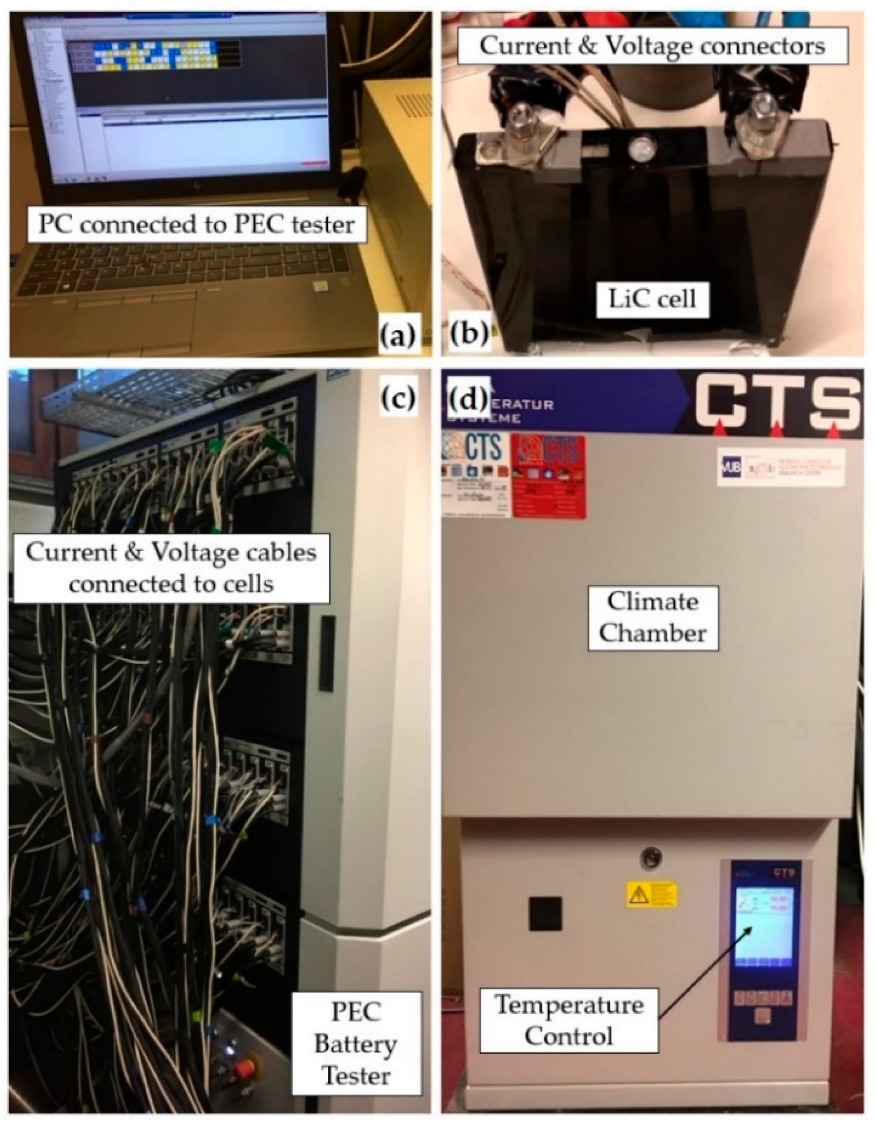
2. Experimental Procedures

The experimental test bench comprises ten commercial prismatic LiCs. The JSR company has produced the cells under the commercial name of ULTIMO cells. The specifications of the cells used are shown in Table 1. The energy density of the used LiC at the ambient temperature of 25 °C and discharge current of 100 A is 14 Wh/L, with a specific energy of 8 Wh/kg. The power density of the used LiC at maximum continuous discharge current is 14.7 kW/L, where its specific power is 9 kW/kg. The nominal capacity of the employed LiC at constant current discharge rate of 10 A is 1 Ah. The maximum current rate that can be applied to the cells is 500 A continuous with a 1100 A pulse current.
Half of the LiCs were used for characterization and for the SOC and temperature analysis regarding the electrical parameters, while the other cells were employed for validation purposes. The nominal capacitance of the LiC is 2300 F. The LiC cells were charged and discharged continuously with high current rates over time to achieve the lowered capacities. The experimental test bench is shown in Figure 1.
The PEC battery cycler was employed for applying the voltage and current rates. A CTS climate chamber was used to control the environment temperature and to set various temperatures for the experiments. The voltage and current cables were connected to the LiCs in the climate chamber. Before each test, the temperature of the climate chamber was set, and the LiCs rested in that temperature for half an hour to perfectly match the internal temperature of the LiCs with the ambient temperature. A computer with software to control the PEC battery tester was used to collect the current and voltage data. The tests were defined for high-power applications that are expected to generate excess heat from cells [63].
The characterization of the LiCs included the preconditioning test, the captest, the OCV test (open circuit voltage), the HPPC test (hybrid pulse power characterization), and verification [59]. The algorithm used to implement the proposed equivalent circuit is illustrated in Figure 2. The preconditioning of LiCs included constant current constant voltage (CCCV) charging of the cells under 10 C (capacitance) and constant current discharging of cells under 10 C. The CCCV charging and CC discharging in this step was applied in ten cycles followed by 600 s of rest. The captest was used to check the capacity of cells subjected to a CCCV charging and CC discharging with 1 C followed by an 1800 s rest. The OCV test included CCCV charging with 1 C followed by a 3600 s rest. Then, the cells were discharged by 5% SOC to obtain the minimum cut-off voltage. Each discharge was followed by a 3600 s rest, and then, the cells were recharged by 5% CC until they were fully charged.
The HPPC test was performed at various levels of SOC. HPPC means hybrid pulse power characterization, in which the cells are charged under 1C with CCCV followed by a 3600 s rest. After the cells were fully charged, discharging with 5% under 1C followed by a 3600 s rest was applied. A set of 10 A to 500 A charge and discharge pulses were applied until the cells reached the cut-off voltage. The ohmic resistance and polarization resistance can also be calculated by the HPPC. In addition, the power capability considering the battery voltage in charge and discharge was measured by the HPPC by applying 10 s pulses of charge and discharge at different SOC values. These pulses should be applied during the time that SOC is constant. The battery should rest for 1 h, and then should be fully charged to start the HPPC. Then, the battery should be discharged to the next SOC value, prior to the next profile start. Nevertheless, the 10 s pulses cannot be applied to the LiC cells due to the drastic change in the SOC value because of the limited storage capacity and high currents. In this regard, each pulse should change the SOC value by a maximum of 0.5%. Therefore, 10 s pulses have been replaced by 2 s pulses to keep the SOC change below the 5% limit. The pulse duration should be decreased appropriately for the higher applied current rates. A dynamic driving cycle was selected to verify the robustness of the developed second-order semi-empirical ECM, as is shown in Figure 3. The tested temperature ranges were between the freezing temperature of −30 °C to +60 °C, which is unique.

3. Equivalent Circuit Model (ECM) Development and Trend Analysis

3.1. The Second-Order Equivalent Circuit Model (ECM)

The second-order ECM is a semi empirical model that is shown in Figure 4. The model has two RC branches due to its asymmetric structure. By applying a high current to the model, the output should be the cell’s voltage as a response. An ideal voltage source can represent the OCV, that corresponds to the LiC SOC. Ro accounts for the ohmic resistance of the cell. The first parallel RC branch (R1 and C1) and the second RC branch (R2 and C2) show the transient behavior of the LiC. The terminal voltage ( V t ) is calculated as in [64]:
V t = O C V S o C , T I L R 0 S o C , T , I L V C P 1 S o C , T , I L V C P 2 S o C , T , I L
d V C P i d t = 1 R P i C P i V C P i + 1 C P i I L
τ i = R P i C P i
where I L represents the cell current, CP denotes the polarization capacitance, RP is the polarization resistance, and τ i is the model’s time constant. Indices 1 and 2 indicate the first and second RC branches. V C P 1 and V C P 2 are the voltage in the first and second polarization capacitance branches, respectively.
The ECM consists of two look-up tables (LUTs) for OCV (one for charge and one for discharge), two LUTs for the charge/discharge ohmic resistance, two LUTs for the first parametrization resistance (charge/discharge), two LUTs for the second parametrization resistance (charge/discharge), two LUTs for the first time constant (charge/discharge), and two LUTs for the second time constant (charge/discharge). Moreover, one LUT for the charge capacity and one LUT for the discharge capacity have been employed for the SOC calculation. These LUTs are responsible for storing the identified parameters.

3.2. The LiC Cell Characterization Results and Trend Analysis

The relation between OCV and SOC can be achieved by slowly charging and discharging LiCs and measuring the voltage during the charge and discharge process [65]. The OCV–SOC curve shown in Figure 5 is at the beginning of the LiC’s life. However, this curve should not be changed that much when the cells are aged. The experiment was carried out at various temperature ranging from −30 °C to +60 °C, and the LUTs were built.
The electrical parameters of the developed model, such as ohmic and polarization resistances and polarization capacitance are functions of temperature and SOC. Developing the second-order model can estimate these parameters. In the MATLAB model, we first tested the cells. The inputs were set, such as the initial state of charge, initial temperature, initial capacity, initial internal resistance, and initial number of cycles. This way, we can calculate the electrical parameters for ohmic resistance, polarization resistance, and time constant as a function of SOC, current rate, and temperature. Then, these values were used in the LUTs to make the developed model. These initial parameters and the LUTs were responsible for calculating the voltage and the heat generation of the cell based on the equations. That is why we call it a semi-empirical model.
Table 2 shows the ECM’s estimated electrical parameters at 25 °C. It is worth mentioning that all these parameters have been generated for the other temperatures such as −10 °C, 0 °C, 10 °C, 40 °C, 50 °C, and 60 °C. The table includes the applied current of 10 A, 20 A, 50 A, 70 A, 100 A, 150 A, 200 A, 300 A, 400 A, and 500 A. Three SOC values have been considered in the table, including 25% SOC, 50% SOC, and 100% SOC to compare how the electrical parameters differ at different SOC values. Ro-dis(Ω) denotes the ohmic resistance, Rp1-dis(Ω) denotes the polarization resistance for the first RC branch, Rp2-dis(Ω) denotes the polarization resistance for the second RC branch, τ1 (s) denotes the time constant for the first RC branch, and τ2 (s) denotes the time constant for the second RC branch. The time constant can be calculated by Equation (3).
The electrical parameters that were estimated were used in the LUTs inside the model to mimic the voltage behavior of the LiC cell. Then, the simulated voltage was verified against the experimentally measured voltage to check the accuracy of the developed second-order ECM. The evaluation was based on 0% SOC to 100%, with a step of 5%, which means we evaluated 21 SOC values: 0%, 5%, 10%, 15%, 20%, 25%, 30%, 35%, 40%, 45%, 50%, 55%, 60%, 65%, 70%, 75%, 80%, 85%, 90%, 95%, and 100%. In Table 2, we only listed three values among the tested SOC values (25%, 50%, 100%).
Figure 6 demonstrates that decreasing the temperature increased the ohmic resistance (Ro-dis(Ω)) sharply, regardless of the health status of the cell. Moreover, when the LiC ages, the ohmic resistance increased. When the ohmic resistance is increased by 200%, the cell is called a dead cell (end-of-life degradation). This behavior is even sharper when the operating temperature is too cold, meaning that the ohmic resistance increased faster. Additionally, the behavior of ohmic resistance at different SOC values is seen in the figure.
Figure 6a shows the ohmic resistance change in various SOCs and currents at −10 °C. Figure 6b shows the ohmic resistance change in various SOCs and currents at 0 °C. Figure 6c shows the ohmic resistance change in various SOCs and currents at 10 °C. Figure 6d shows the ohmic resistance change in various SOCs and currents at 25 °C. Figure 6e shows the ohmic resistance change in various SOCs and currents at 40 °C. Figure 6f shows the ohmic resistance change in various SOCs and currents at 50 °C. Figure 6g shows the ohmic resistance change in various SOCs and currents at 60 °C.
This trend is the same for the polarization resistances for both RC branches, meaning they increase by decreasing the temperature. However, polarization resistance changed sharply with SOC variation. However, the polarization capacitances for both RC branches rose with temperature. All in all, the electrical parameters of ohmic resistance, polarization capacitance, and polarization resistance changed significantly at different current rates, temperatures, and SOC values. Therefore, it can be concluded that these electrical parameters are functions of the current rate, temperature, and SOC.
The sensitivity analysis is of high importance for each experimental test. Therefore, by using the error of data measurement and accuracy of each facility that was used in the experimental test bench, the uncertainty analysis was performed. The method of Cole has been employed in this context for our test bench. Therefore, the uncertainty error is calculated as follows [66]:
U R = i = 1 n R V I U V I 2 1 / 2
In this equation, each factor’s error is denoted by U V I . In addition, the total number of errors is shown by U R . After calculation of the error regarding Table 3, the maximum uncertainty of the experimental tests can be calculated as 1.17%.
This work uses a semi-empirical ECM to represent the relation between various electrical parameters as functions of the current rate, temperature, and SOC. The range of SOC employed in this work was from 10% to 100%, meaning that the depth of discharge is 90%. Such a SOC range is quite normal for real driving cycles and applications. Within this SOC range, the results proved that the relation between ohmic resistance, polarization resistance, and polarization capacitance with the current rate, temperature, and SOC is somehow monotonic functions. This trend proves the claim that the developed model is second order, and the RC branches increase the detail and precision of the proposed ECM. Thus, the suitability for real applications like battery management system can be enhanced.
The electrical parameters of the second-order ECM at 25 °C can be seen in Figure 7. Figure 7a shows the polarization resistance for the first RC branch, and Figure 7b depicts the polarization resistance for the second RC branch. Additionally, Figure 7c illustrates the time constant for the first RC branch, and Figure 7d demonstrates the time constant for the second RC branch. A comparison can be made for these electrical parameters with Figure 6, where the ohmic resistance has been illustrated.

4. Validation of the Second-Order ECM

Figure 8 depicts the results of the developed second-order ECM regarding the voltage validation. Figure 8a gives information about the experimental and simulation analysis curves for voltage in 10,000 s in the high dynamic driving cycle. Figure 8b shows the error of analysis for the measured voltage vs. simulated voltage during 10,000 s. The error was calculated based on the experimental and simulation voltage error. In this context, the voltage from the beginning to the end of the experiment was measured.
On the other hand, the model calculated the simulated ECM’s voltage from the beginning to the end of the simulation time. The error was measured in each time step by subtracting the simulation and experimental voltage values. Therefore, the curve in Figure 8b is the voltage error for each step time.
As is evident, the developed model can mimic the behavior of voltage in the real world, showing the model’s performance and precision in such a high dynamic driving cycle. In addition, where the current rate was less than 150 A, the error of ECM was lower than 3%, which is perfect. However, when the demanded power was high, in current rates above 150 A, the simulation error was lower than 5%. This trend proves that using a second-order semi-empirical model led to the development of a high-precision model for hybrid LiC cells. Such a model can also be linked to the thermal model to generate the system’s heat loss, which is vital for heat transfer modeling and computational fluid dynamics analysis [67]. It is worth mentioning that these 3% and 5% calculated errors are the maximum percentage that has been calculated, not an average. Therefore, the maximum error of voltage that can be achieved by comparing the simulation and experimental results was 5% for the highest or current rate. Moreover, the maximum error of voltage that can be achieved by comparing the simulation and experimental results for the current rates below 150 A was 3%.

5. Conclusions

In this work, an enhanced ECM was developed for high-power lithium-ion capacitors (LiC) for a wide range of temperatures from the freezing temperature of −30 °C to the hot temperature of +60 °C, under high current rates from 10 A to 500 A, which is unique. In this context, experimental tests were carried out to mimic the behavior of the LiC by modeling a semi-empirical second-order ECM. The precision of the ECM could be increased by adding the order, but the complexity would also be increased, resulting in higher computational costs. Since the structure of the LiC cell is asymmetric, two resistance and capacitance (RC) branches were required to maintain the accuracy of the model. The following remarks can be highlighted:
  • The electrical parameters were generated at other temperatures such as −10 °C, 0 °C, 10 °C, 40 °C, 50 °C, and 60 °C. The table includes the applied current of 10 A, 20 A, 50 A, 70 A, 100 A, 150 A, 200 A, 300 A, 400 A, and 500 A.
  • The SOC range was from 0% to 100%, but in this paper, three SOC values have been listed in the table, including 25% SOC, 50% SOC, and 100% SOC, to compare how the electrical parameters differ at different SOC values.
  • The results proved that decreasing the temperature increases the ohmic resistance sharply, regardless of the health status of the cell. Moreover, when the LiC was aged, the ohmic resistance was increased. When the ohmic resistance was increased by 200%, the cell is called a dead cell (end-of-life degradation).
  • This behavior was even sharper when the operating temperature was too cold, meaning that the ohmic resistance increased faster. This trend was the same for the polarization resistances for both RC branches, which was increased by decreasing the temperature. However, polarization resistance was changed sharply with SOC variation.
  • The validation results exhibit that, where the current rate was less than 150 A, the error of the developed ECM was lower than 3%. When the demanded power was high, in current rates above 150 A, the error of the developed model was lower than 5%.

Author Contributions

Conceptualization, D.K.; methodology, D.K.; software, D.K.; validation, D.K.; formal analysis, D.K.; investigation, D.K.; data curation, D.K.; writing—original draft preparation, D.K.; writing—review and editing, H.B., J.V.M., and M.B.; visualization, D.K.; supervision, J.V.M. and M.B.; All authors have read and agreed to the published version of the manuscript.

Funding

This research received no external funding.

Data Availability Statement

Not applicable.

Acknowledgments

This research has been made possible thanks to the JSR company.

Conflicts of Interest

The authors declare no conflict of interest.

References

  1. Van Mierlo, J.; Berecibar, M.; El Baghdadi, M.; De Cauwer, C.; Messagie, M.; Coosemans, T.; Jacobs, V.; Hegazy, O. Beyond the State of the Art of Electric Vehicles: A Fact-Based Paper of the Current and Prospective Electric Vehicle Technologies. World Electr. Veh. J. 2021, 12, 20. [Google Scholar] [CrossRef]
  2. Khaleghi, S.; Hosen, M.; Karimi, D.; Behi, H.; Beheshti, S.; Van Mierlo, J.; Berecibar, M. Developing an online data-driven approach for prognostics and health management of lithium-ion batteries. Appl. Energy. 2022, 308, 118348. [Google Scholar] [CrossRef]
  3. Kim, G.; Pesaran, A.; Spotnitz, R. A three-dimensional thermal abuse model for lithium-ion cells. J. Power Sources. 2007, 170, 476–489. [Google Scholar] [CrossRef]
  4. Karimi, D.; Behi, H.; Van Mierlo, J.; Berecibar, M. Novel Hybrid Thermal Management System for High-Power Lithium-Ion Module for Electric Vehicles: Fast Charging Applications. World Electr. Veh. J. 2022, 13, 86. [Google Scholar] [CrossRef]
  5. Soltani, M.; Berckmans, G.; Jaguemont, J.; Ronsmans, J.; Kakihara, S.; Hegazy, O.; Van Mierlo, J.; Omar, N. Three dimensional thermal model development and validation for lithium-ion capacitor module including air-cooling system. Appl. Therm. Eng. 2019, 153, 264–274. [Google Scholar] [CrossRef]
  6. Soltani, M.; Beheshti, S. A comprehensive review of lithium ion capacitor: Development, modelling, thermal management and applications. J. Energy Storage 2021, 34, 102019. [Google Scholar] [CrossRef]
  7. Akbarzadeh, M.; Kalogiannis, T.; Jin, L.; Karimi, D.; Van Mierlo, J.; Berecibar, M. Experimental and numerical thermal analysis of a lithium-ion battery module based on a novel liquid cooling plate embedded with phase change material. J. Energy Storage. 2022, 50, 104673. [Google Scholar] [CrossRef]
  8. Karimi, D.; Behi, H.; Van Mierlo, J.; Berecibar, M. A Comprehensive Review of Lithium-Ion Capacitor Technology: Theory, Development, Modeling, Thermal Management Systems, and Applications. Molecules 2022, 27, 3119. [Google Scholar] [CrossRef]
  9. Soltani, M.; Ronsmans, J.; Kakihara, S.; Jaguemont, J.; Van den Bossche, P.; van Mierlo, J.; Omar, N. Hybrid battery/lithium-ion capacitor energy storage system for a pure electric bus for an urban transportation application. Appl. Sci. 2018, 8, 1176. [Google Scholar] [CrossRef]
  10. Karimi, D.; Behi, H.; Akbarzadeh, M.; Khaleghi, S.; Van Mierlo, J.; Berecibar, M. Optimization of 1D/3D Electro-Thermal Model for Liquid-Cooled Lithium-Ion Capacitor Module in High Power Applications. Electricity 2021, 2, 503–523. [Google Scholar] [CrossRef]
  11. Karimi, D.; Behi, H.; Van Mierlo, J.; Berecibar, M. An Experimental Study on Thermal Performance of Graphite-Based Phase-Change Materials for High-Power Batteries. Energies 2022, 15, 2515. [Google Scholar] [CrossRef]
  12. Sedlakova, V.; Sikula, J.; Majzner, J.; Sedlak, P.; Kuparowitz, T.; Buergler, B.; Vasina, P. Supercapacitor equivalent electrical circuit model based on charges redistribution by diffusion. J. Power Sources. 2015, 286, 58–65. [Google Scholar] [CrossRef]
  13. Karimi, D.; Hosen, M.; Behi, H.; Khaleghi, S.; Akbarzadeh, M.; Van Mierlo, J.; Berecibar, M. A hybrid thermal management system for high power lithium-ion capacitors combining heat pipe with phase change materials. Heliyon 2021, 7, e07773. [Google Scholar] [CrossRef] [PubMed]
  14. Li, C.; Zhang, C.; Wang, K.; Yu, F.; Xie, J.; Zhang, Q. Multi-thiol-supported dicarboxylate-based metal–organic framework with excellent performance for lithium-ion battery. Chem. Eng. J. 2022, 431, 133234. [Google Scholar] [CrossRef]
  15. Li, C.; Zhang, C.; Xie, J.; Wang, K.; Li, J.; Zhang, Q. Ferrocene-based metal-organic framework as a promising cathode in lithium-ion battery. Chem. Eng. J. 2021, 404, 126463. [Google Scholar] [CrossRef]
  16. Wang, H.; Yao, C.; Nie, H.; Wang, K.; Zhong, Y.; Chen, P.; Mei, S.; Zhang, Q. Recent progress in carbonyl-based organic polymers as promising electrode materials for lithium-ion batteries (LIBs). J. Mater. Chem. A 2020, 8, 11906–11922. [Google Scholar] [CrossRef]
  17. Li, C.; Yang, H.; Xie, J.; Wang, K.; Li, J.; Zhang, Q. Ferrocene-Based Mixed-Valence Metal-Organic Framework as an Efficient and Stable Cathode for Lithium-Ion-Based Dual-Ion Battery. ACS Appl. Mater. Interfaces 2020, 12, 32719–32725. [Google Scholar] [CrossRef]
  18. Behi, H.; Karimi, D.; Kalogiannis, T.; He, J.; Patil, M.; Muller, J.-D.; Haider, A.; Van Mierlo, J.; Berecibar, M. Advanced hybrid thermal management system for LTO battery module under fast charging. Case Stud. Therm. Eng. 2022, 33, 101938. [Google Scholar] [CrossRef]
  19. Jaguemont, J.; Van Mierlo, J. A comprehensive review of future thermal management systems for battery-electrified vehicles. J. Energy Storage. 2020, 31, 101551. [Google Scholar] [CrossRef]
  20. Karimi, D.; Behi, H.; Akbarzadeh, M.; Van Mierlo, J.; Berecibar, M. A Novel Air-Cooled Thermal Management Approach towards High-Power Lithium-Ion Capacitor Module for Electric Vehicles. Energies 2021, 14, 7150. [Google Scholar] [CrossRef]
  21. Patel, J.; Rathod, M. Recent developments in the passive and hybrid thermal management techniques of lithium-ion batteries. J. Power Sources 2020, 480, 228820. [Google Scholar] [CrossRef]
  22. Akbarzadeh, M.; Jaguemont, J.; Kalogiannis, T.; Karimi, D.; He, J.; Jin, L.; Xie, P.; Van Mierlo, J.; Berecibar, M. A novel liquid cooling plate concept for thermal management of lithium-ion batteries in electric vehicles. Energy Convers. Manag. 2021, 231, 113862. [Google Scholar] [CrossRef]
  23. Gandoman, F.; Behi, H.; Berecibar, M.; Jaguemont, J.; Aleem, S.; Behi, M.; Van Mierlo, J. Chapter 16—Reliability evaluation of Li-ion batteries for electric vehicles applications from the thermal perspectives. In Uncertainties in Modern Power Systems; Zobaa, A.F., Abdel Aleem, S.H.E., Eds.; Academic Press: Cambridge, MA, USA, 2021; pp. 563–587. [Google Scholar] [CrossRef]
  24. Liu, H.; Wei, Z.; He, W.; Zhao, J. Thermal issues about Li-ion batteries and recent progress in battery thermal management systems: A review. Energy Convers. Manag. 2017, 150, 304–330. [Google Scholar] [CrossRef]
  25. Karimi, D.; Berecibar, M.; Van Mierlo, J. Modular Methodology for Developing Comprehensive Active and Passive Thermal Management Systems for Electric Vehicles, Vrije Universiteit Brussel. 2022. Available online: https://researchportal.vub.be/en/publications/modular-methodology-for-developing-comprehensive-active-and-passi (accessed on 13 April 2022).
  26. Karimi, D.; Behi, H.; Jaguemont, J.; Berecibar, M.; Van Mierlo, J. A refrigerant-based thermal management system for a fast charging process for lithium-ion batteries. In Proceedings of the International Conference on Renewable Energy Systems and Environmental Engineering (IRESE2020), Brussels, Belgium, 18–20 July 2020; Global Publishers: Glendale, WI, USA, 2020; pp. 1–6. [Google Scholar]
  27. Akbarzadeh, M.; Kalogiannis, T.; Jaguemont, J.; Jin, L.; Behi, H.; Karimi, D.; Beheshti, H.; Van Mierlo, J.; Berecibar, M. A comparative study between air cooling and liquid cooling thermal management systems for a high-energy lithium-ion battery module. Appl. Therm. Eng. 2021, 198, 117503. [Google Scholar] [CrossRef]
  28. Karimi, D.; Behi, H.; Hosen, M.; Jaguemont, J.; Berecibar, M.; Van Mierlo, J. A compact and optimized liquid-cooled thermal management system for high power lithium-ion capacitors. Appl. Therm. Eng. 2021, 185, 116449. [Google Scholar] [CrossRef]
  29. Giuliani, F.; Delmonte, N.; Cova, P. Thermal-Fluid Dynamic FEM Simulation of Advanced Water Cold Plates for Power Electronics. In Proceedings of the COMSOL Conference, Milan, Italy, 10–12 October 2012. [Google Scholar]
  30. Behi, H.; Behi, M.; Karimi, D.; Jaguemont, J.; Ghanbarpour, M.; Behnia, M.; Berecibar, M.; Van Mierlo, J. Heat pipe air-cooled thermal management system for lithium-ion batteries: High power applications. Appl. Therm. Eng. 2020, 183, 116240. [Google Scholar] [CrossRef]
  31. Behi, H.; Karimi, D.; Behi, M.; Jaguemont, J.; Ghanbarpour, M.; Behnia, M.; Berecibar, M.; Van Mierlo, J. Thermal management analysis using heat pipe in the high current discharging of lithium-ion battery in electric vehicles. J. Energy Storage 2020, 32, 101893. [Google Scholar] [CrossRef]
  32. Behi, H.; Karimi, D.; Jaguemont, J.; Gandoman, F.; Khaleghi, S.; Van Mierlo, J.; Berecibar, M. Aluminum heat sink assisted air-cooling thermal management system for high current applications in electric vehicles. In Proceedings of the 2020 AEIT International Conference of Electrical and Electronic Technologies for Automotive (AEIT AUTOMOTIVE), Turin, Italy, 18–20 November 2020; Institute of Electrical and Electronics Engineers Inc.: Piscataway, NJ, USA, 2020. [Google Scholar] [CrossRef]
  33. Behi, H.; Behi, M.; Ghanbarpour, A.; Karimi, D.; Azad, A.; Ghanbarpour, M.; Behnia, M. Enhancement of the Thermal Energy Storage Using Heat-Pipe-Assisted Phase Change Material. Energies 2021, 14, 6176. [Google Scholar] [CrossRef]
  34. Karimi, D.; Behi, H.; Jaguemont, J.; Sokkeh, M.; Kalogiannis, T.; Hosen, M.; Berecibar, M.; Van Mierlo, J. Thermal performance enhancement of phase change material using aluminum-mesh grid foil for lithium-capacitor modules. J. Energy Storage 2020, 30, 101508. [Google Scholar] [CrossRef]
  35. Möller, S.; Karimi, D.; Vanegas, O.; El Baghdadi, M.; Kospach, A.; Lis, A.; Hegazy, O.; Abart, C.; Offenbach, Â. Application considerations for Double Sided Cooled Modules in Automotive Environment. 2020. Available online: https://ieeexplore.ieee.org/document/9097721 (accessed on 16 November 2020).
  36. Karimi, D.; Behi, H.; Jaguemont, J.; Berecibar, M.; Van Mierlo, J. Optimized air-cooling thermal management system for high power lithium-ion capacitors. Energy Perspect. 2020, 1, 93. [Google Scholar]
  37. Karimi, D.; Behi, H.; Jaguemont, J.; Berecibar, M.; Van Mierlo, J. Investigation of extruded heat sink assisted air cooling system for lithium-ion capacitor batteries. In Proceedings of the International Conference on Renewable Energy Systems and Environmental Engineering, Brussels, Belgium, 18–20 July 2020; Global Publishers: Glendale, WI, USA, 2020; pp. 1–6. [Google Scholar]
  38. Behi, H.; Karimi, D.; Behi, M.; Ghanbarpour, M.; Jaguemont, J.; Sokkeh, M.; Gandoman, F.; Berecibar, M.; Van Mierlo, J. A new concept of thermal management system in Li-ion battery using air cooling and heat pipe for electric vehicles. Appl. Therm. Eng. 2020, 174, 115280. [Google Scholar] [CrossRef]
  39. Behi, H.; Karimi, D.; Youssef, R.; Patil, M.S.; Van Mierlo, J.; Berecibar, M. Comprehensive Passive Thermal Management Systems for Electric Vehicles. Energies 2021, 14, 3881. [Google Scholar] [CrossRef]
  40. Behi, H.; Karimi, D.; Gandoman, F.; Akbarzadeh, M.; Khaleghi, S.; Kalogiannis, T.; Hosen, M.; Jaguemont, J.; Van Mierlo, J.; Berecibar, M. PCM assisted heat pipe cooling system for the thermal management of an LTO cell for high-current profiles. Case Stud. Therm. Eng. 2021, 25, 100920. [Google Scholar] [CrossRef]
  41. Karimi, D.; Behi, H.; Jaguemont, J.; El Baghdadi, M.; Van Mierlo, J.; Hegazy, O. Thermal Concept Design of MOSFET Power Modules in Inverter Subsystems for Electric Vehicles. In Proceedings of the 2019 9th International Conference on Power and Energy Systems (ICPES), Perth, WA, Australia, 10–12 December 2019. [Google Scholar] [CrossRef]
  42. Behi, H.; Karimi, D.; Jaguemont, J.; Berecibar, M.; Van Mierlo, J. Experimental study on cooling performance of flat heat pipe for lithium-ion battery at various inclination angels. Energy Perspect. 2020, 1, 77. [Google Scholar]
  43. Jaguemont, J.; Karimi, D.; Van Mierlo, J. Investigation of a Passive Thermal Management System for Lithium-Ion Capacitors. IEEE Trans. Veh. Technol. 2019, 68, 10518–10524. [Google Scholar] [CrossRef]
  44. Karimi, D.; Jaguemont, J.; Behi, H.; Berecibar, M.; Van Den Bossche, P.; Van Mierlo, J. Passive cooling based battery thermal management using phase change materials for electric vehicles. In Proceedings of the EVS33—33nd Electric Vehicle Symposium, Portland, OR, USA, 14–17 June 2020; pp. 1–12. [Google Scholar]
  45. Hosen, M.; Karimi, D.; Kalogiannis, T.; Pirooz, A.; Jaguemont, J.; Berecibar, M.; Van Mierlo, J. Electro-aging model development of nickel-manganese-cobalt lithium-ion technology validated with light and heavy-duty real-life profiles. J. Energy Storage 2020, 28, 101265. [Google Scholar] [CrossRef]
  46. Movassagh, K.; Raihan, A.; Balasingam, B.; Pattipati, K. A Critical Look at Coulomb Counting Approach for State of Charge Estimation in Batteries. Energies 2021, 14, 4074. [Google Scholar] [CrossRef]
  47. Wu, L.; Pang, H.; Geng, Y.; Liu, X.; Liu, J.; Liu, K. Low-complexity state of charge and anode potential prediction for lithium-ion batteries using a simplified electrochemical model-based observer under variable load condition. Int. J. Energy Res. 2022, 46, 11834–11848. [Google Scholar] [CrossRef]
  48. Lucu, M.; Martinez-Laserna, E.; Gandiaga, I.; Camblong, H. A critical review on self-adaptive Li-ion battery ageing models. J. Power Sources 2018, 401, 85–101. [Google Scholar] [CrossRef]
  49. Ahmed, R.; Rahimifard, S.; Habibi, S. Offline Parameter Identification and SOC Estimation for New and Aged Electric Vehicles Batteries. In Proceedings of the 2019 IEEE Transportation Electrification Conference and Expo (ITEC), Detroit, MI, USA, 19–21 June 2019. [Google Scholar] [CrossRef]
  50. Mohammedi, M.; Kraa, O.; Becherif, M.; Aboubou, A.; Ayad, M.; Bahri, M. Fuzzy logic and passivity-based controller applied to electric vehicle using fuel cell and supercapacitors hybrid source. Energy Procedia 2014, 50, 619–626. [Google Scholar] [CrossRef]
  51. Lyu, P.; Liu, X.; Qu, J.; Zhao, J.; Huo, Y.; Qu, Z.; Rao, Z. Recent advances of thermal safety of lithium ion battery for energy storage. Energy Storage Mater. 2020, 31, 195–220. [Google Scholar] [CrossRef]
  52. Zhang, L.; Hu, X.; Wang, Z.; Sun, F.; Dorrell, D. A review of supercapacitor modeling, estimation, and applications: A control/management perspective. Renew. Sustain. Energy Rev. 2018, 81, 1868–1878. [Google Scholar] [CrossRef]
  53. Gandolfo, D.; Brandão, A.; Patiño, D.; Molina, M. Dynamic model of lithium polymer battery—Load resistor method for electric parameters identification. J. Energy Inst. 2015, 88, 470–479. [Google Scholar] [CrossRef]
  54. Tran, M.; Fowler, M. Sensor Fault Detection and Isolation for Degrading Lithium-Ion Batteries in Electric Vehicles Using Parameter Estimation with Recursive Least Squares. Batteries 2019, 6, 1. [Google Scholar] [CrossRef]
  55. Gao, Z.; Chin, C.; Woo, W.; Jia, J. Integrated equivalent circuit and thermal model for simulation of temperature-dependent LiFePO4 battery in actual embedded application. Energies 2017, 10, 85. [Google Scholar] [CrossRef]
  56. Khaleghi, S.; Karimi, D.; Beheshti, S.; Hosen, S.; Behi, H.; Berecibar, M.; Van Mierlo, J. Online health diagnosis of lithium-ion batteries based on nonlinear autoregressive neural network. Appl. Energy 2021, 282, 116159. [Google Scholar] [CrossRef]
  57. Omar, N.; Daowd, M.; Hegazy, O.; Al Sakka, M.; Coosemans, T.; Van Den Bossche, P.; Van Mierlo, J. Assessment of lithium-ion capacitor for using in battery electric vehicle and hybrid electric vehicle applications. Electrochim. Acta 2012, 86, 305–315. [Google Scholar] [CrossRef]
  58. Firouz, Y.; Omar, N.; Timmermans, J.; Van den Bossche, P.; Van Mierlo, J. Lithium-ion capacitor—Characterization and development of new electrical model. Energy 2015, 83, 597–613. [Google Scholar] [CrossRef]
  59. Soltani, M.; De Sutter, L.; Ronsmans, J.; van Mierlo, J. A high current electro-thermal model for lithium-ion capacitor technology in a wide temperature range. J. Energy Storage 2020, 31, 101624. [Google Scholar] [CrossRef]
  60. Plett, G. Extended Kalman filtering for battery management systems of LiPB-based HEV battery packs: Part 1. Background. J. Power Sources. 2004, 134, 252–261. [Google Scholar] [CrossRef]
  61. Pang, H.; Guo, L.; Wu, L.; Jin, J.; Zhang, F.; Liu, K. A novel extended Kalman filter-based battery internal and surface temperature estimation based on an improved electro-thermal model. J. Energy Storage 2021, 41, 102854. [Google Scholar] [CrossRef]
  62. Pang, H.; Jin, J.; Wu, L.; Zhang, F.; Liu, K. A Comprehensive Physics-Based Equivalent-Circuit Model and State of Charge Estimation for Lithium-Ion Batteries. J. Electrochem. Soc. 2021, 168, 090552. [Google Scholar] [CrossRef]
  63. Behi, H.; Karimi, D.; Jaguemont, J.; Gandoman, F.; Kalogiannis, T.; Berecibar, M.; Van Mierlo, J. Novel thermal management methods to improve the performance of the Li-ion batteries in high discharge current applications. Energy 2021, 224, 120165. [Google Scholar] [CrossRef]
  64. Karimi, D.; Behi, H.; Akbarzadeh, M.; Van Mierlo, J.; Berecibar, M. Holistic 1D Electro-Thermal Model Coupled to 3D Thermal Model for Hybrid Passive Cooling System Analysis in Electric Vehicles. Energies 2021, 14, 5924. [Google Scholar] [CrossRef]
  65. Hosen, M.; Kalogiannis, T.; Youssef, R.; Karimi, D.; Behi, H.; Jin, L.; Van Mierlo, J.; Berecibar, M. Twin-model framework development for a comprehensive battery lifetime prediction validated with a realistic driving profile. Energy Sci. Eng. 2021, 9, 2191–2201. [Google Scholar] [CrossRef]
  66. Sheikholeslami, M.; Ganji, D. Heat transfer enhancement in an air to water heat exchanger with discontinuous helical turbulators; experimental and numerical studies. Energy 2016, 116, 341–352. [Google Scholar] [CrossRef]
  67. Karimi, D.; Khaleghi, S.; Behi, H.; Beheshti, H.; Hosen, M.; Akbarzadeh, M.; Van Mierlo, J.; Berecibar, M. Lithium-ion capacitor lifetime extension through an optimal thermal management system for smart grid applications. Energies 2021, 14, 2907. [Google Scholar] [CrossRef]
Figure 1. The experimental test bench: (a) computer connected to the PEC battery tester, (b) the LiC cell with connected current and voltage cables, (c) PEC battery tester with current and voltage cables connected to the LiC cells, (d) CTS climate chamber to control the ambient temperature for the tests. The temperatures used for the experiments range from −30 °C to +60 °C.
Batteries 09 00101 g001
Figure 2. The algorithm used to implement the proposed equivalent circuit.
Batteries 09 00101 g002
Figure 3. (Left) Dynamic current profile applied to the LiC cells during 10,000 s from −250 A to +250 A current rate, (right) zoomed frame of the applied dynamic current from 4000 s to 5000 s that shows the dynamic behavior of the applied current rate.
Batteries 09 00101 g003
Figure 4. Schematic of the second-order semi-empirical equivalent circuit model.
Batteries 09 00101 g004
Figure 5. The experimental curve for the OCV–SOC of the LiC cell.
Batteries 09 00101 g005
Figure 6. The behavior of ohmic resistance at different SOC and current rates: (a) −10 °C, (b) 0 °C, (c) 10 °C, (d) 25 °C, (e) 40 °C, (f) 50 °C, (g) 60 °C.
Batteries 09 00101 g006
Figure 7. The electrical parameters of the second-order ECM at 25 °C: (a) the polarization resistance for the first RC branch, (b) the polarization resistance for the second RC branch, (c) the time constant for the first RC branch, (d) the time constant for the second RC branch.
Batteries 09 00101 g007
Figure 8. Validation of the second-order ECM: (a) verification of the simulation and experimental results of voltage, (b) error of validation.
Batteries 09 00101 g008
Table 1. Specifications of the target cells used in the test bench.
SpecificationValue/Unit
Number of cells10
Capacitance2300 F
Min. cut-off voltage2.2 V
Max. cut-off voltage3.8 V
Weight350 g
Width150 mm
Height93 mm
Thickness15.5 mm
Table 2. The ECM’s estimated electrical parameters at 25 °C.
Current (A)SOC (%)Ro-dis(Ω)Rp1-dis(Ω)Rp2-dis(Ω)τ1 (s)τ2 (s)
1025 1.95 × 10 3 7.23 × 10 2 1.65 × 10 4 1.56 × 10 2 6.19 × 10 1
1050 1.81 × 10 3 1.08 × 10 1 1.53 × 10 4 2.03 × 10 2 1.50 × 10 1
10100 1.73 × 10 3 6.81 × 10 2 1.77 × 10 4 1.52 × 10 2 2.04 × 10 1
2025 1.98 × 10 3 6.52 × 10 2 1.61 × 10 4 9.85 × 10 1 2.99 × 10 1
2050 1.83 × 10 3 7.10 × 10 2 1.36 × 10 4 1.45 × 10 2 1.43 × 10 1
20100 1.72 × 10 3 5.49 × 10 2 1.49 × 10 4 9.47 × 10 1 1.62 × 10 1
5025 1.66 × 10 3 3.64 × 10 2 1.59 × 10 4 6.82 × 10 1 1.94 × 10 1
5050 1.52 × 10 3 5.30 × 10 2 1.36 × 10 4 9.83 × 10 1 1.32 × 10 1
50100 1.46 × 10 3 3.08 × 10 2 1.45 × 10 4 7.74 × 10 1 1.44 × 10 1
7025 1.59 × 10 3 3.60 × 10 2 1.42 × 10 4 6.84 × 10 1 2.34 × 10 1
7050 1.44 × 10 3 5.97 × 10 2 1.21 × 10 4 1.05 × 10 2 1.53 × 10 1
70100 1.31 × 10 3 2.86 × 10 2 1.26 × 10 4 7.14 × 10 1 1.94 × 10 1
10025 1.43 × 10 3 2.78 × 10 2 1.43 × 10 4 5.13 × 10 1 1.63 × 10 1
10050 1.33 × 10 3 4.83 × 10 2 1.26 × 10 4 8.45 × 10 1 1.32 × 10 1
100100 1.26 × 10 3 2.50 × 10 2 1.35 × 10 4 6.35 × 10 1 1.46 × 10 1
15025 1.30 × 10 3 2.42 × 10 2 1.50 × 10 4 4.38 × 10 1 1.33 × 10 1
15050 1.21 × 10 3 3.60 × 10 2 1.28 × 10 4 6.99 × 10 1 1.16 × 10 1
150100 1.15 × 10 3 2.29 × 10 2 1.36 × 10 4 5.66 × 10 1 1.33 × 10 1
20025 1.20 × 10 3 2.22 × 10 2 1.61 × 10 4 4.01 × 10 1 1.22 × 10 1
20050 1.10 × 10 3 4.03 × 10 2 1.29 × 10 4 6.34 × 10 1 1.23 × 10 1
200100 1.05 × 10 3 2.03 × 10 2 1.43 × 10 4 5.29 × 10 1 1.47 × 10 1
30025 1.08 × 10 3 1.89 × 10 2 1.67 × 10 4 3.52 × 10 1 1.06 × 10 1
30050 9.95 × 10 4 3.98 × 10 2 1.31 × 10 4 5.61 × 10 1 1.07 × 10 1
300100 9.46 × 10 4 2.02 × 10 2 1.41 × 10 4 4.82 × 10 1 1.28 × 10 1
40025 9.86 × 10 4 1.83 × 10 2 1.97 × 10 4 3.30 × 10 1 1.00 × 10 1
40050 9.28 × 10 4 3.51 × 10 2 1.32 × 10 4 5.26 × 10 1 1.10 × 10 1
400100 8.76 × 10 4 1.52 × 10 2 1.41 × 10 4 4.30 × 10 1 1.13 × 10 1
50025 9.28 × 10 4 1.72 × 10 2 1.44 × 10 4 3.62 × 10 1 1.19 × 10 1
50050 8.51 × 10 4 3.46 × 10 2 1.30 × 10 4 5.18 × 10 1 1.00 × 10 1
500100 8.08 × 10 4 1.72 × 10 2 1.42 × 10 4 4.26 × 10 1 1.20 × 10 1
Table 3. Specifications of each channel of the battery testers.
ParameterPrecisionResolution
Current0–50 (A)±0.03%100 µA
Voltage0–5 (V)±0.03%200 µV
Temperature−40–200 (°C)±0.2%0.1 °C
Disclaimer/Publisher’s Note: The statements, opinions and data contained in all publications are solely those of the individual author(s) and contributor(s) and not of MDPI and/or the editor(s). MDPI and/or the editor(s) disclaim responsibility for any injury to people or property resulting from any ideas, methods, instructions or products referred to in the content.

