
Polyaniline—Graphene Electrodes Prepared by Electropolymerization for High-Performance Capacitive Electrodes: A Brief Review


1
TEMA—Centre for Mechanical Technology and Automation, Department of Mechanical Engineering, University of Aveiro, 3810-193 Aveiro, Portugal
2
LASI—Intelligent Systems Associate Laboratory, 4800-058 Guimaraes, Portugal
3
CICECO—Aveiro Institute of Materials, Department of Materials and Ceramic Engineering, University of Aveiro, 3810-193 Aveiro, Portugal
*
Authors to whom correspondence should be addressed.
Batteries 2022, 8(10), 191; https://doi.org/10.3390/batteries8100191
Submission received: 19 August 2022
/
Revised: 14 September 2022
/
Accepted: 14 October 2022
/
Published: 17 October 2022
(This article belongs to the Special Issue Energy Conversion and Storage: Recent Advances and Prospects)
Abstract
:Both polyaniline (PANI) and graphene are widely studied for their application as capacitive electrodes in energy storage devices. However, although PANI can be easy synthesized, is of low cost and has a higher specific capacitance than graphene, pristine PANI electrodes do not present long-term stability due to their large volume changes during release/doping of the electrolyte ions and surface area reduction with charge-discharge cycling. That is why a combination of PANI with carbonaceous materials, especially conductive and high-surface-area graphene as well as more widely used reduced graphene oxide (rGO), provides an effective approach to solve these problems. At the same time, the electropolymerization process is one of the possible methods for synthesis of PANI composites with G or rGO as freestanding electrodes. Therefore, no binders or additives such as carbon black or active carbon need to be used to obtain PANI/rGO electrodes by electrochemical polymerization (EP), in contrast to similar electrodes prepared by the chemical oxidative polymerization method. Thus, in this paper, we review recent advances in EP synthesis of PANI/rGO nanocomposites as high-performance capacitive electrode materials, combining the advantages of both electrical double-layer capacitance of rGO and pseudocapacitance of PANI, which hence exhibit long cycle life and high specific energy.
1. Introduction
Energy storage is one of the most important topics in scientific research today after solar, wind or other types of energy transformation development. Besides batteries, electrochemical capacitors (often called supercapacitors (SC)) are widely studied as energy storage devices for their commercial applications in electrical cars, portable electronics, etc. [1,2]. The most famous electrode materials with electric double layer capacitor (EDLC) behaviour in both batteries and SC are carbon-based compounds [3], including activated carbon [4], porous carbons [5], graphene (G) as well as reduced graphene oxide (rGO) [6,7,8], carbide-derived carbons [9], carbon xerogels [10] or carbon nanotubes [11] and their combinations [12,13,14]. However, the reported capacitances of carbonaceous materials are typically about 300–400 F/g in spite of high specific surface areas [15,16]. For instance, activated carbon, with a possible specific surface area up to 2500–3000 m2/g and pore volume approximately 2 cm3/g [17], can exhibit relatively low specific capacitance since its very small pore size (<2 nm in the majority) limits the electrolyte to access the entire surface area [18,19,20]. On the other hand, carbon-family materials have shown almost 100% chemical stability after a high number of charging-discharging cycles and their addition to composites significantly enhances the cycling stability. One of the most studied energy storage materials is reduced graphene oxide that can be relatively easily obtained as large flakes compared with monolayer graphene, but it can still show high electrical conductivity, great mechanical strength and large specific surface area [21].
At the same time, conducting polymers such as polyaniline (PANI) with high theoretical capacitance up to 2000 F/g [22] are frequently used for pseudocapacitor electrode materials because of their low cost, facile synthesis and high flexibility [23,24]. However, the poor electrochemical cyclic stability of PANI due to large volume changes during release/doping of the electrolyte ions [24,25], together with a decrease in the surface area after charge-discharge cycling [26], limits its application. So far, the stability of polyaniline-based supercapacitors could be improved by means of dynamically evolving emulsion polymerization strategy or nano-compounding strategy [27]. Therefore, composites of PANI and carbonaceous materials have attracted extensive attention due to their superior electrochemical performance by combining the advantages of the electrochemical double-layer capacitance of carbonaceous materials and pseudocapacitance of PANI [28].
In a majority of the reported studies on the preparation of PANI-containing electrodes for supercapacitors [29,30], as well as for batteries [31,32,33,34,35,36,37,38], the chemical oxidative polymerization (COP) method, based on a simple mixture of aniline monomer with an oxidative agent, typically in acid, was used for PANI synthesis. However, in this case, the obtained powders use to be combined with additives/binders to form the electrode. In contrast, PANI (as well as a mixture of PANI with other materials such as graphene or reduced graphene oxide) can be directly deposited onto a conductive substrate (including graphene-based) by the electrochemical polymerization (EP) method. Thus, EP showed advantageous possibilities for fabricating binder-free and flexible electrodes of PANI and graphene or reduced graphene oxide (for simplicity, both are designated here as PANI/rGO) as well as for maintaining a uniform thickness for the PANI layer. Despite this, to the best of our knowledge, there is just one recent report on PANI/rGO-based battery electrodes prepared by the EP method. A composite cathode of PANI on the graphene oxide (GO) layer prepared on a surface of graphite paper presented the specific capacity of 276 mAh/g and specific energy of 386 mWh/g, which is suggested for the new seawater battery application [39].
Interesting and important reviews were conducted on the use of PANI with graphene-related materials for different research areas, especially for energy storage as supercapacitors [28,29,30,40,41], including flexible supercapacitors [42]; however, they did not focus on the electropolymerization process for the composite electrode preparation. At the same time, there are a number of recent advances on the EP preparation of PANI/rGO nanocomposites as electrode materials for supercapacitors, and they are presented in this review. The available information is summarized and several factors determining the electrochemical performances of the PANI/rGO nanocomposites are also discussed.
2. PANI/rGO Electrodes by Electropolymerization
2.1. Layered PANI/rGO Structures
During the EP of PANI, conductive substrates use to perform a function of the working electrode in the three-electrode system (as illustrated in Figure 1a), which works in constant voltage (or current), pulsed or cyclic voltammetry (CV) modes. A layered structure of PANI on rGO (PANI/rGO) obtained after the EP process is a common feature when the electrolyte consists of an acid such as H2SO4 or HCl and aniline (ANI) monomer and does not contain rGO. Furthermore, electrode CV increases in area when PANI is electropolymerized onto, e.g., vacuum-filtrated (VF) graphene paper (G-paper) compared to CV of G-paper only, as demonstrated in Figure 1b,c [43], resulting in higher specific capacitance.
In the main part of the available reports on studies of EP PANI/rGO-layered structures summarized in Table 1, graphene-based materials were used as conductive substrates [43,44,45,46,47,48,49]. Of these, a significant number of reports demonstrated graphene or rGO freestanding films or papers as effective conductive substrates for PANI grown by in situ EP, resulting in individual PANI layers [44,45,48]. To achieve that, graphene oxide (GO) solution can be deposited onto an A4 paper template [44], or simply dried as freestanding film [45,48] or prepared by VF [47] with the following chemical or thermal reduction.
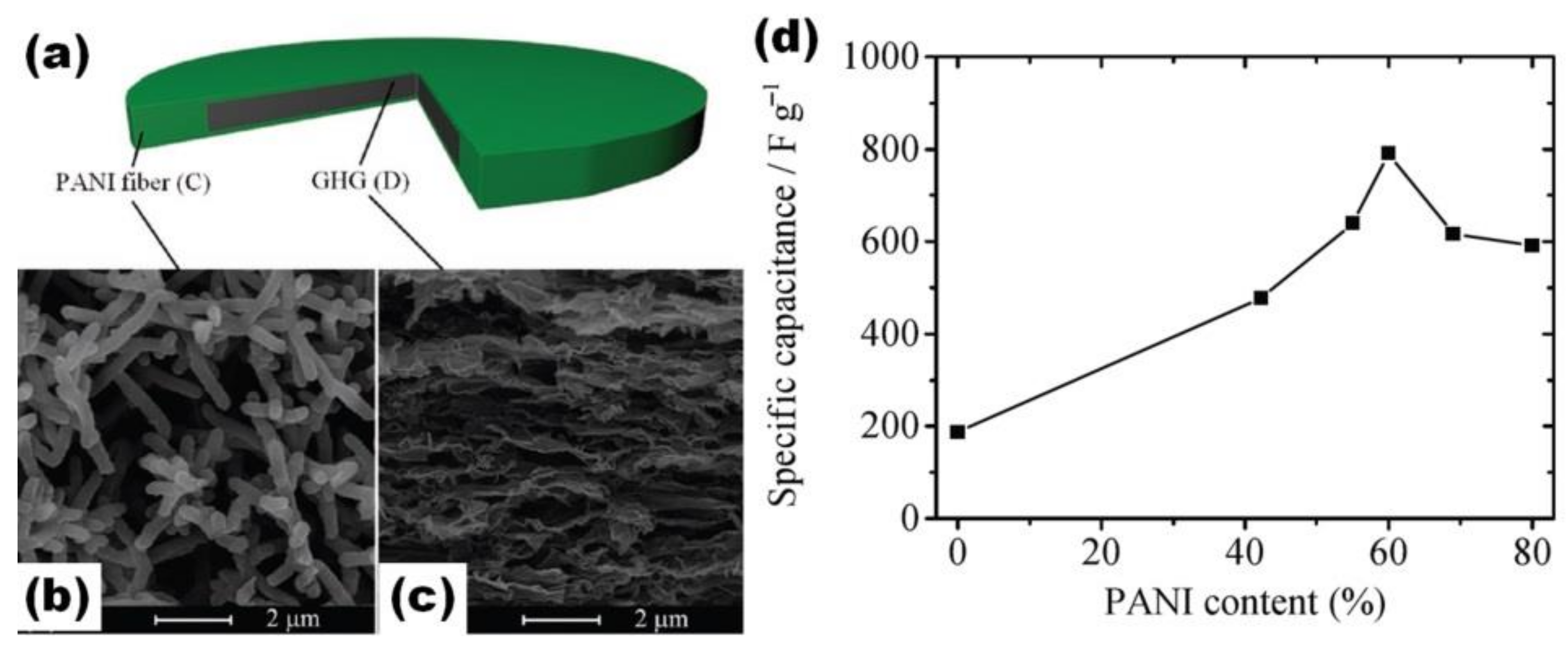
Figure 1d–f shows the layered composites obtained by EP in the three-electrode system at constant 0.8 V for 60 s on rGO freestanding paper, prepared by covering A4 paper by GO with the following drying, peeling and chemical reduction [44]. The green colour (seen in Figure 1d) confirmed the growth of PANI as a highly porous (Figure 1e) and continuous (Figure 1f) layer. The obtained freestanding and flexible PANI/rGO electrode presented specific capacitance of 522 F/g at 1 A/g (with 60 wt% rGO and 40 wt% PANI), which is much higher than the 55 F/g measured for pristine rGO film.
Figure 1.
Illustration of the PANI EP on G-paper in the three-electrode system (a), cyclic voltammograms of G-paper (b) and graphene/polyaniline composite paper (GPCP) prepared by EP for 900 s (c) (Reprinted with permission of [43]. Copyright 2009 American Chemical Society). Photograph of rGO, PANI/rGO and rGO/PANI/rGO papers (d), with top view (e) and cross-sectional view (f) microstructures of PANI/rGO paper [44].

A higher specific capacitance value of 763 F/g at 1 A/g was reported by Cong et al. for PANI/rGO with 22.3 wt% PANI prepared on freestanding rGO paper for 600 s EP process at 0.8 V [45]. Such capacitance was much higher than that of pristine rGO, while the cycling stability of PANI/rGO increased to 82% after 1000 cycles in comparison to only 52% for pristine PANI. Polyaniline nanowire arrays were also grown by EP on graphene sheets in partially exfoliated graphite foil (Ex-GF) as conductive substrates for 5400 s with constant current density of 0.5 mA/cm2 by Ye et al. [46]. Such a PANI/Ex-GF electrode presented a specific capacitance of 840 F/g at 1 A/g and stability of 80.6% at 20 A/g after 10,000 cycles [46].
Jin et al. prepared freestanding nitrogen-doped porous graphene (NPG) paper by vacuum filtration and microwave-initiated chain reduction to be used as a support for PANI nanocones electropolymerized at 0.7 V from an electrolyte containing 0.05 M aniline, 0.5 M camphorsulphonic acid (CSA) and 0.1 M tetraethylammonium tetrafluoroborate (Et4NBF4) [47]. A specific capacitance up to 400 F/g at 1 mA/cm2 was reported for the prepared electrodes [47]. A much higher specific capacitance of 759 F/g was measured by Lv et al. for PANI grown on rGO paper at the same 0.8 V but only for 30 s and glued by silver paste on indium tin oxide (ITO) substrate [48].

Table 1.
Available data of the specific capacitance, cycling stability and summary processing details of the layered PANI/rGO single electrodes measured in the three-electrode systems or full SC, ordered by type of substrate.
Table 1.
Available data of the specific capacitance, cycling stability and summary processing details of the layered PANI/rGO single electrodes measured in the three-electrode systems or full SC, ordered by type of substrate.
| Substrate | Electrolyte | Details of Polymerization Process (and Composite Component Contents or PANI Mass Loading) | Specific Capacitance (F/g) of rGO, PANI, PANI/rGO Electrodes (rGO//PANI//PANI/rGO) or SC Based on These (at Current Density or Scan Rate) | Cycling Stability (%) of PANI/rGO Electrodes or SC Based on These (at Cycle Number, Current Density or Scan Rate) | Specific Energy (Wh/kg)/Specific Power (W/kg) of Symmetric SC (Electrolyte Type, Potential Window) | Ref. |
|---|---|---|---|---|---|---|
| rGO paper (VF of graphene suspension) | 0.5 M H2SO4, 0.05 M ANI | 0.75 V, 900 s | single electrode: 147//-//233 (20 mV/s) | single electrode: >100 (1500, 20 mV/s) | - | [43] |
| rGO paper (GO on A4 paper template, HI, sodium bicarbonate) | 1 M HCl, 0.3 M ANI | 0.8 V and 2 mA/cm2, 60 s (rGO:PANI as 3:2) | single electrode: 55//-//522 (1 A/g) | single electrode: 57 (10,000, 10 A/g) | - | [44] |
| rGO paper (GO, HI) | 1 M H2SO4, 0.1 M ANI | 0.8 V, 600 s (22.3 wt% PANI) | single electrode: 180//-//763 (1 A/g) | single electrode: 82 (1000, 5 A/g) | - | [45] |
| Partially exfoliated G foil | 1 M HClO4, 0.05 M ANI | 0.5 mA/cm2, 5400 s (1.29 mg/cm2) | single electrode: -//-//840 (1 A/g) | single electrode: 80.6 (10,000, 20 A/g) | - | [46] |
| N-doped rGO paper (GO, γ-ray irradiation reduction, VF) | 0.05 M ANI, 0.5 M CSA, 0.1 M Et4NBF4 | 0.7 V, 2 C/cm2 | single electrode: -//-//330 (1 mA/cm2) | - | - | [47] |
| rGO paper (GO, HI, 90 °C, 2 h) on ITO | 1 M H2SO4, 0.1 M ANI | 0.8 V, 30 s | single electrode: -//-//759 (1 A/g) | - | - | [48] |
| rGO hydrogel (GO, sodium ascorbate, HT 90 °C, 1.5 h, pressed disk) | 1 M H2SO4, 0.4 M ANI | CV mode from –0.2 to +0.8 V at 10 mV/s (61 wt% PANI) | single electrode: -//-//791 (1.14 A/g) | - | - | [49] |
| 3D G grown by CVD on Ni foam template | 1 M HClO4, 0.1 M ANI | 0.65 mA/cm2, 2500 s (7.1 wt% PANI, 92.9 wt% G) | single electrode: -//-//751 (1 A/g) | single electrode: 93.2 (1000, 4 mA/cm2) | - | [50] |
| G grown on wavy-shaped Ni foam template | 1 M H2SO4, 0.5 M ANI | pulsed mode, pulse length of 4 s, 60 cycles at 2 mA/cm2 | SC: -//-//261 (0.38 A/g) (based on mass of PANI) | SC: 89 (1000, 1 mA/cm2) | 23.2/399 (H3PO4-PVA, 0–+0.8 V) | [51] |
| G woven fabric (by CVD) | 1 M HCl, 0.5 M ANI | 0.8 V, 900 s | SC: 67 (0.1 mA/cm2)//-//771 | SC: 100 (2000, -) | 15 mWh/m2/ 0.33 mW/cm2 (H3PO4-PVA, −0.4–+0.6 V) | [52] |
| G-coated polyester textile | 1 M H2SO4, 0.1 M ANI | 0.75 V (10 wt% PANI, 0.2 mg/cm2) | single electrode: -//-//896 (1 A/g) | SC: 75.55 (1000, 10 A/g) | 13.11/200 (H3PO4-PVA, 0–+0.8 V) | [53] |
| Hydrogen-bonded G on ITO | 1.0 M KOH, 0.1 M ANI | 50 cycles from 0 V to 1.0 V | single electrode: -//217//598 (1 A/g) | single electrode: 95 (5000, 1 A/g) | - | [54] |
| rGO (GO, hydrazine vapour) on PDMS | 0.5 M H2SO4, 0.05 M ANI | 0.75 V, 4500 s (26% rGO) | SC: -//1268//973 (2.5 A/g) | SC: 90 (1700, 2.5 A/g) | - | [55] |
In addition to free-standing rGO films or papers, 3D porous graphene frameworks such as graphene hydrogel (GH) prepared by hydrothermal method (HT) were used as a substrate for PANI EP deposition [49,56,57]. However, an obvious PANI layer can only be observed on GH preliminary pressed into disk form by Wu et al. [49] to obtain a denser structure before the polymerization process. In addition, Wu et al. studied the influence of additional GH immersion into an electrolyte for 24 h before the electrodeposition for the monomer diffusion into the pressed GH disc [49]. The specific capacitance of electrodes prepared with additional immersion was found to be 789 F/g at a low current density of 1.35 A/g that was comparable with 791 F/g at 1.14 A/g for electrodes without preliminary immersion. However, the specific capacitance of the electrodes without preliminary immersion decreases by 43% toward 450 F/g with an increase of the current density to 27 A/g in contrast to the electrodes after immersion, keeping ~790 F/g at 27 A/g [49].
One more porous substrate such as reduced graphene oxide foam (GF) was obtained by Yu et al. using Ni foam as a template during chemical vapour deposition (CVD) of graphene with the following etching of the Ni framework to obtain a 3D graphene network [50]. The best electrode reported by Yu et al. was prepared onto GF after 2500 s of the EP process, contained only 7.1 wt% PANI, and presented the specific capacitance of 751 F/g together with high cycling stability of 93.2% after 1000 cycles and 4 mA/cm2 [50].
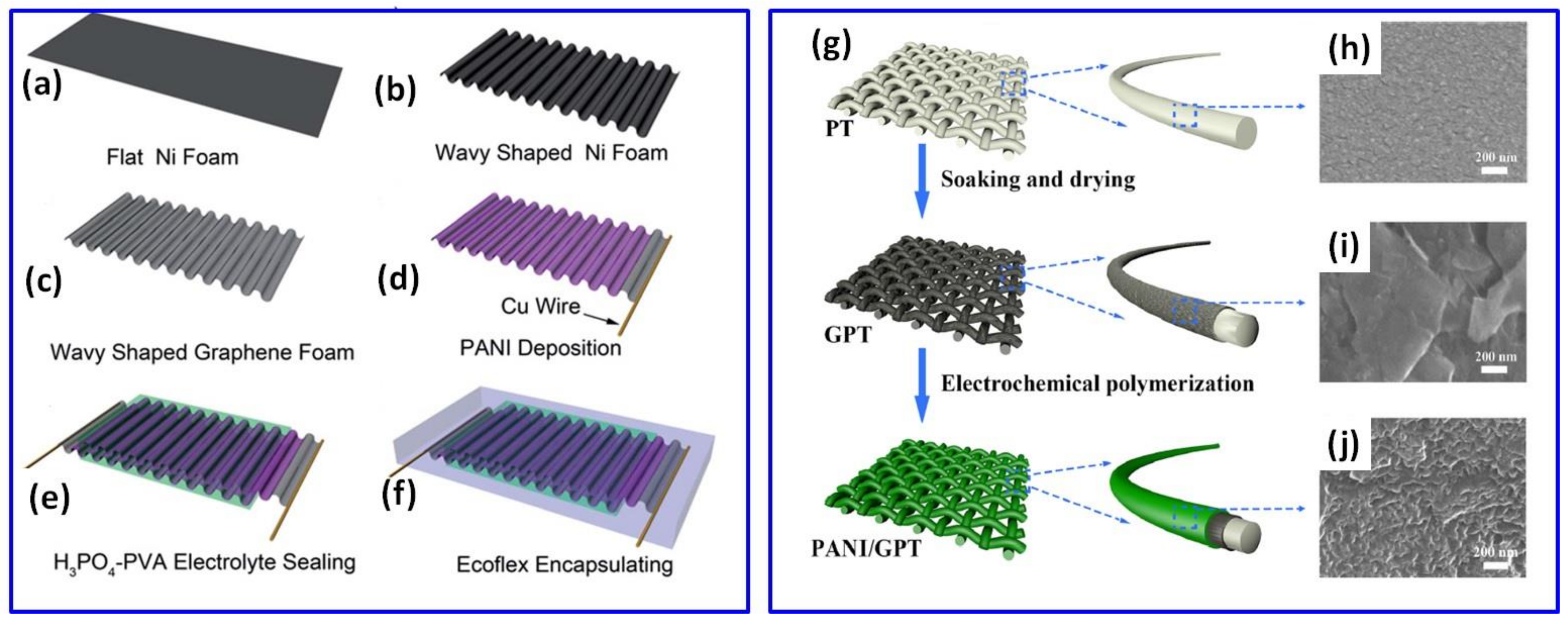
At the same time, Xie et al. used a porous graphene sheet prepared with a wavy shape after Ni foam dissolving (Figure 2a–f) for the PANI deposition by a pulsed EP process and fabrication of the stretchable wavy-shaped supercapacitor with H3PO4-polyvinyl alcohol (PVA) electrolyte (Figure 2f) [51]. According to a rough calculation of the characteristics of a sine wave, it was predicted that the wavy-shaped graphene can be stretched by approximately 30%. Symmetric supercapacitors made of these layered PANI/waved-graphene electrodes presented the specific capacitance of 261 F/g at 0.38 A/g (based on total mass of PANI) and 89% cycling stability after 1000 cycles at 1 mA/cm2 [51].
In addition to freestanding graphene papers and freestanding 3D graphene frameworks, textile material covered by graphene, including graphene woven fabric (GWF) [52] and graphene-coated polyester textile (GPT) (Figure 2g–j) [53] can be used as a support for PANI. A symmetric supercapacitor made of PANI electropolymerized on GWF at 0.8 V for 900 s from 1 M HCl and 0.5 M ANI electrolyte has shown a specific capacitance of 771 F/g [52], which is comparable to 897 F/g reported for the single PANI on GPT electrode prepared at 0.75 V from 1 M H2SO4 with 0.1 M ANI electrolyte [53]. Moreover, the device on such PANI/GWF electrodes was found to be very stable with 100% response after 2000 cycles [52]. In addition, Lin et al. prepared a PANI layer on carbon woven fabric (CWF) by EP at 0.65 V from 1 M H2SO4 with 0.1 M ANI electrolyte and obtained an electrode with the specific capacitance of ~375 F/g at 1 A/g [58].
Figure 2.
Schematic description of stretchable supercapacitor fabrication: flat Ni foam (a), wavy-shaped Ni foam (b), preparation of porous graphene in a wave shape by using Ni foam as a catalyst (c), deposition of PANI onto porous graphene via pulsed electrochemical deposition (d), coating with H3PO4-PVA gel electrolyte (e) and encapsulation of supercapacitor in elastomeric Ecoflex (f) (Reprinted from [51] with permission of RSC Publishing). Schematic illustration for the preparation of PANI/GPT textile electrode (g), microstructures of polyester textile (PT) (h), PT covered by graphene (GPT) (i) and PANI/GPT (j) (Reprinted from [53] with permission of Wiley).

Besides the graphene-based supports, conductive indium tin oxide (ITO) glass substrate was also used for the deposition of hydrogen-bonded graphene (HbG) and the following electropolymerization of PANI [54]. The preparation of HbG lamellar structure on ITO increased the specific capacitance from 217 F/g for pristine PANI on ITO to 598 F/g at 1 A/g for PANI prepared on ITO with HbG [54].
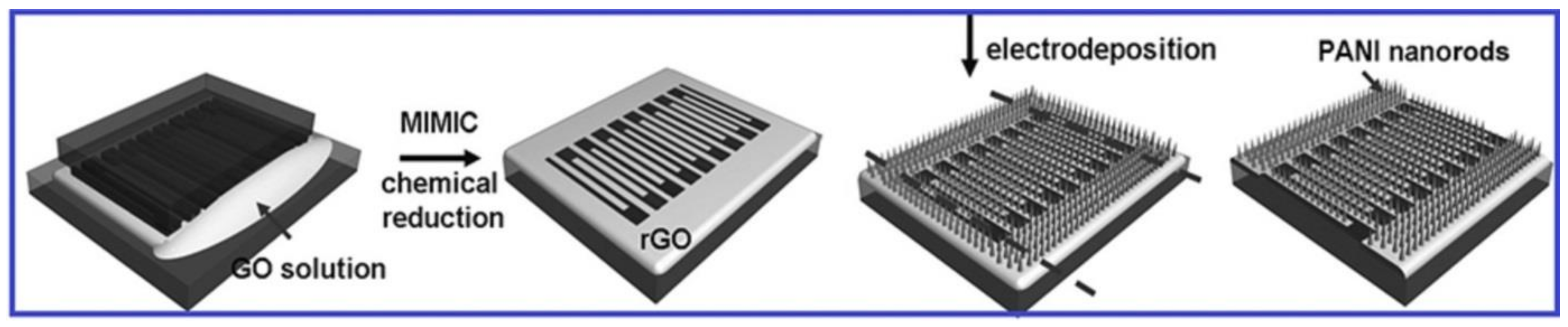
In addition, a supercapacitor based on patterned interdigital finger PANI/rGO electrodes on polydimethylsiloxane (PDMS) substrate was prepared by Xue et al. [55]. That involved a layer of PANI nanorod arrays being electropolymerized on chemically reduced and patterned graphene oxide film on PDMS substrate in the three-electrode system at constant 0.75 V for 4500 s (Figure 3). The obtained planar supercapacitor made of PANI/rGO electrodes has shown the highest specific capacitance of 973 F/g at 2.5 A/g (or 1268 F/g based on PANI weight only) among those listed in Table 1, with high cycling stability of 90% at 2.5 A/g after 1700 cycles [55].
Figure 3.
Fabrication of patterned interdigital finger PANI/rGO microelectrodes (Reprinted from [55] with permission of Wiley).
Figure 3.
Fabrication of patterned interdigital finger PANI/rGO microelectrodes (Reprinted from [55] with permission of Wiley).

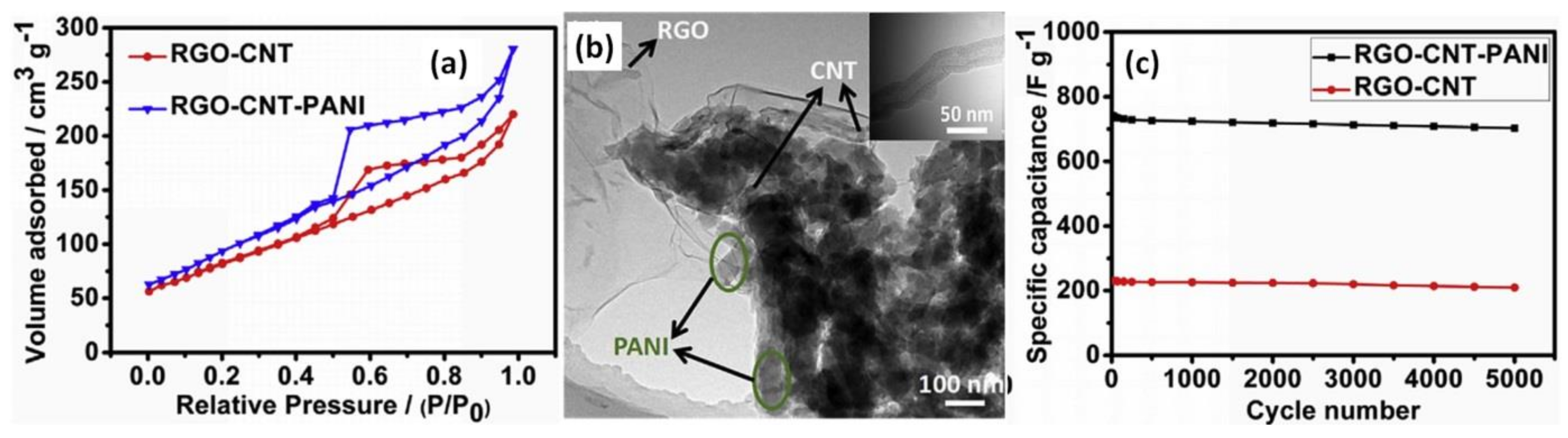
Another possible approach to increase the specific capacitance of PANI with rGO was to add a layer of carbon nanotubes (CNT) obtained by floating catalyst chemical vapour deposition between rGO deposited by electrophoretic deposition on Ni foam and an electropolymerized PANI layer (from 0.5 M H2SO4 and 0.2 M ANI), as reported by Xiong et al. [59]. After the electropolymerization process induced by altering the voltage between 1.4 V and 3.0 V from 5 min to 30 min, surface areas increased from 245 m2/g for rGO-CNT to 312 m2/g for rGO-CNT covered by PANI, as can be seen from the N2 adsorption/desorption isotherms of rGO-CNT and rGO-CNT-PANI in Figure 4a. The larger specific area of rGO-CNT-PANI was explained by the introduction of PANI nanofibers used as a spacer to prevent the rGO from further agglomerating, as shown in the transmission electron microscopy (TEM) image of rGO-CNT-PANI (Figure 4b) in which the rGO-CNT coexists with PANI nanofibers (marked by the arrows). CNT (shown in the inset of Figure 4b) could be used as a conductive bridge interconnected between rGO and PANI nanofibers. Such a structure of rGO-CNT-PANI increases the conductivity of the hybrid material and can facilitate the access of electrolyte ions to the inner of the electrode material. As shown in Figure 4c, the specific capacitance of 816 F/g at 2 A/g and cycling stability of 95% at 10 mV/s after 5000 cycles were measured in Li2SO4 electrolyte for SCs prepared on PANI/CNT/rGO electrodes, which is significantly higher than the results obtained for rGO with CNT only [59].
Figure 4.
The N2 adsorption/desorption isotherms of rGO-CNT-PANI and rGO-CNT materials (a). TEM images of rGO-CNT-PANI (b), with CNT nanofibers presented in the inset. Cycling performance of the rGO-CNT-PANI and rGO-CNT electrodes at a scan rate of 10 mV/s (c) (Reprinted from [59], Copyright 2017, with permission of Elsevier).

2.2. Multilayer and Inverse PANI/rGO Structures
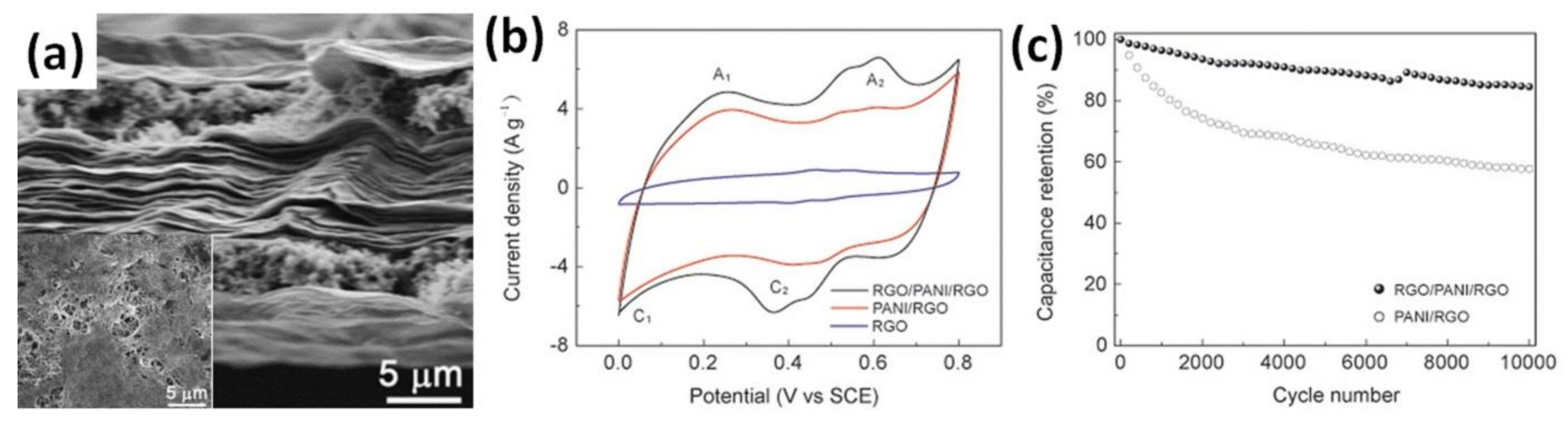
An additional layer of rGO on already prepared PANI on conductive substrate was reported to improve the electrochemical properties of the final electrode, as summarized in Table 2 [44,60]. When PANI/rGO was completely covered by a layer of rGO after deep coating and reduction that resulted in the rGO/PANI/rGO structure, as shown in Figure 5a, an increase of the specific capacitance of PANI/rGO (60 wt% rGO and 40 wt% PANI) from 522 F/g to 581 F/g at 1 A/g was reported by Xiao et al., as shown in Figure 5b. Moreover, the cycling stability of the obtained multilayer structure was also reported to increase, as shown in Figure 5c [44].
Figure 5.
Cross-sectional view of microstructure of rGO/PANI/rGO papers (a) (inset is top view). CV curves of rGO/PANI/rGO, PANI/rGO and rGO paper electrodes at a scan rate of 10 mV/s in 1 M H2SO4 electrolyte (b). Cycle performance of rGO/PANI/rGO and PANI/rGO paper electrodes at 10 A/g over 10,000 cycles (c) [44].

Table 2.
Available data of the specific capacitance, cycling stability and summary processing details of the layered PANI/rGO single electrodes measured in three-electrode systems or full SC.
Table 2.
Available data of the specific capacitance, cycling stability and summary processing details of the layered PANI/rGO single electrodes measured in three-electrode systems or full SC.
| Substrate | Electrolyte | Details of Polymerization Process (and Composite Component Contents or PANI Mass Loading) | Specific Capacitance of Prepared Electrodes or SC Based on These (at Current Density or Scan Rate) | Cycling Stability (%) of Prepared Electrodes or SC Based on These (at Cycle Number, Current Density or Scan Rate) | Specific Energy (Wh/kg)/Specific Power (W/kg) of Symmetric SC (Electrolyte Type, Potential Window) | Ref. |
|---|---|---|---|---|---|---|
| rGO paper (GO on A4 paper template, HI, sodium bicarbonate) | 1 M HCl, 0.3 M ANI | 0.8 V and 2 mA/cm2, 60 s (rGO:PANI as 3:2) | rGO/PANI/rGO single electrode: 581 F/g (1 A/g) | rGO/PANI/rGO single electrode: 85 (10,000, 10 A/g) | 10.79/- (H2SO4-PVA, 0–+0.8 V) | [44] |
| Carbon woven fabric (CWF) | 1 M H2SO4, 0.1 M ANI | 0.65 V (2.2 mg/cm2 into GO + PAH, HI) | rGO/PANI/CWF single electrode: 571 F/g or 812 F/cm2 (1 A/g) SC: 790.4 F cm2 (1 A/cm2) | rGO/PANI/CWF single electrode: 88.9 (5000, 10 A/g) SC: 82 (3000/10 A/g) | 28.21 μWh/cm2/ 0.12 mW/cm2 (H2SO4-PVA, 0–+1 V) | [58] |
| Ni foam or ITO | 1 M H2SO4, 0.5 M ANI | CV mode from −0.6 V to 1.4 V at 100 mV/s | ErGO/PANI/Ni or ITO single electrode: 550 (10 mA/g) | ErGO/PANI/Ni or ITO single electrode: ~95 (1000, 1.5 A/g) | 79.4/1000 (H2SO4, −0.2–+0.6 V) | [60] |
CV area and charging/discharging time were also reported to increase (Figure 6a,b) after the additional deposition of the rGO layer on the PANI/GWF surface by sequential dipping into poly(allylamine hydrochloride) (PAH) solution and 0.5, 1, 3 or 5 mg/mL GO dispersion for 5 h with further reduction in HI/ethanol solution [58]. GO concentration was found to play the key role in forming a well-distinguishable wrapping layer. As shown in Figure 6c–f, rGO gradually becomes thicker, from several nanometres to nearly 1 μm, when GO concentration increases from 0.5 mg/mL to 5 mg/mL. When the GO suspension concentration is lower than 1 mg/mL, rGO nanosheets were hardly found at the surface (Figure 6c,d) leaving PANI particles exposed to the ambient area, while rGO nanosheets could foreseeably envelope the whole electrode at a higher concentration. When rGO concentration exceeds 1 mg/mL, the rGO layer has a thickness of several hundred nanometres (Figure 6e) and reaches nearly 1 μm at a concentration of 5 mg/mL (Figure 6f). However, restacking rGO flakes at an elevated GO concentration would hinder the full utilization of the surface area, limiting the accessibility of the electrolyte ions. Thus, while highly aggregated rGO might lower the electrochemical performance, sheets of few graphene layers have been proven to form an interconnected mesoporous network, acting as ion-buffering reservoirs. This resulted in an increase of the specific capacitance up to 571 F/g at 1 A/g after rGO decoration of the PANI/CWF electrode, with the optimal GO concentration of 1 mg/mL in comparison to ~375 F/g reported for PANI/CWF without decoration [58].
Figure 6.
CV (a) and GCD (b) curves and microstructures of rGO/PANI/carbon woven fabric electrodes made with GO concentrations of 0.5 mg/mL (c), 1 mg/mL (d), 3 mg/mL (e) and 5 mg/mL (f). The inset in (f) is a zoom with a scale bar of 1 μm. (Reprinted from [51], Copyright 2018, with permission of Elsevier).

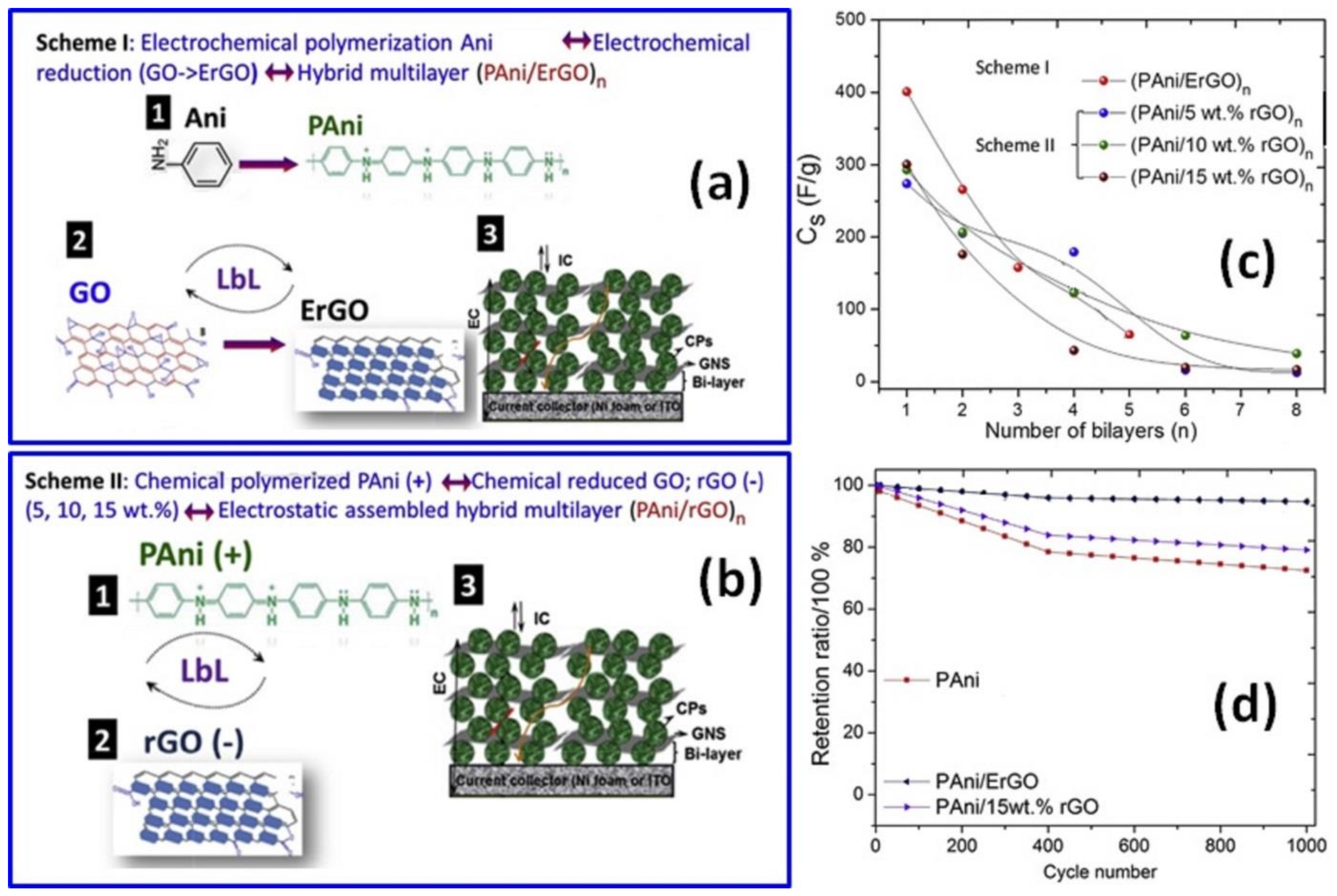
To avoid the GO chemical reduction step, Gupta et al. prepared a PANI layer via in situ EP using a cycling voltammetry mode from −0.6 V to +1.4 V followed by electrochemical reduction of graphene oxide (ErGO) forming ErGO/PANI structures on Ni foam or ITO substrates [60]. To achieve that, water-soluble graphene oxide sheets were drop-casted on as-synthesized PANI and the resulting GO/PANI bi-layer was then placed in an aqueous solution containing 1 M NaCl-based buffer media for 1200 s in amperometric mode at −0.9 V (see scheme I in Figure 7a). Following this scheme, structures with a number of ErGO/PANI bi-layers from 1 to 5 were prepared in a layer-by-layer (LbL) manner, presenting a blend of ErGO nanosheets and PANI nanostructures. On the other hand, when Gupta et al. used already chemically reduced GO solution drop-casted onto a PANI layer prepared by the COP method according to scheme II in Figure 7b, occasional breaking of PANI/rGO films with increasing thickness and characteristic wrinkled graphene nanosheets walls was observed [60]. Correspondingly, one layer of EP ErGO/PANI single electrode and symmetric supercapacitor made of the ErGO/PANI electrodes presented much higher specific capacitance than that of the chemically treated rGO/PANI electrode and corresponding symmetric SC (Figure 7c). As can also be seen in Figure 7c, the specific capacitance of these electrodes decreased with a number of layers. Moreover, the cycling stability of the single ErGO/PANI electrode was ~95% after 1000 cycles at 1.5 A/g, and was higher than that of rGO/PANI and the pristine PANI electrode (Figure 7d) [60].
Figure 7.
Preparation of layer-by-layer (LbL) assembled hybrid films of PANI with GO and ErGO nanosheets on ITO substrates designated as Scheme I (a). Preparation of electrostatic LbL hybrids of PANI with different rGO wt% nanosheets on ITO substrates by Scheme II (b). Specific capacitance for (PANI/ErGO)n and (PANI/rGO)n hybrids prepared using Scheme I and Scheme II with the number of bi-layers n from 1 to 8 (c). Plots of cycle life test of PANI, PANI/ErGO and PANI/15 wt% rGO (d) (Reprinted from [60], Copyright 2016, with permission of Elsevier).

2.3. Mixed PANI/rGO Structures
In addition to the layered structures of PANI/rGO obtained by the EP process, mixed PANI and rGO composites were also prepared by EP when graphene or rGO (or GO with the following reduction) were added into electrolyte containing an acid such as H2SO4 or HCl and aniline monomer (see Table 3).
A mixed PANI/rGO film was prepared by Kakaei et al. from the electrolyte consisting of GO, ANI and sodium dodecyl sulphate (SDS) by EP on carbon paper [61]. A symmetric device with PANI/rGO films prepared for 2 h at a current density of 0.3–0.5 mA/cm2 has shown high stability of 88% after 5000 cycles. Moreover, as reported, the addition of rGO into electrolyte led to increasing specific capacitance from 260 F/g measured for rGO or 430 F/g reported for PANI up to 890 F/g obtained for PANI/rGO [61].
As mentioned in the previous sub-chapter, graphene hydrogel (GH) prepared by the hydrothermal method (HT) was used as a support to obtain a layered PANI/rGO structure in the case of GH pressed into disk form [49]. On the other hand, the use of highly porous GH in electrolyte with ANI leads to incorporation/deposition of PANI on the surface of GH, forming a mixed PANI/rGO structure (Figure 8a) [56,57]. Such electrodes were reported as very stable (90% after 8000 cycles [57] or 93.1% after 5000 cycles [56]). Moreover, independently of the time of the EP process, the electrodes showed high specific capacitance of 710 F/g at 2 A/g (EP at 0.8 V for 1200 s) [56] and 854 F/g at 1 A/g (EP at 0.75 V for 100 s) [57].
Table 3.
Available data of the specific capacitance, cycling stability and summary processing details of mixed PANI/rGO composite single electrodes measured in three-electrode systems or full SC ordered by type of the used substrate.
Table 3.
Available data of the specific capacitance, cycling stability and summary processing details of mixed PANI/rGO composite single electrodes measured in three-electrode systems or full SC ordered by type of the used substrate.
| Substrate | Electrolyte | Details of Polymerization Process (Composite Component Content or PANI Mass Loading) | Specific Capacitance (F/g) of rGO, PANI, PANI/rGO Electrodes (rGO//PANI//PANI/rGO) or SC Based on These (at Current Density or Scan Rate) | Cycling Stability (%) of PANI/rGO Electrodes or SC Based on These (at Cycle Number, Current Density or Scan Rate) | Specific Energy (Wh/kg)/Specific Power (W/kg) of Symmetric SC (Electrolyte Type, Potential Window) | Ref. |
|---|---|---|---|---|---|---|
| Carbon paper | ANI, GO, SDS | 0.3–0.5 mA/cm2, 7200 s | single electrode: 260//430//600 (1 mV/s) | single electrode: 88 (5000, 3 A) | - | [61] |
| GH (GO, HT 180 °C, 14 h) pressed on carbon cloth | HCl, ANI | 0.75 V, 100 s (1 mg/cm2) | single electrode: -//-//854 (1 A/g) SC: -//-//741 (20 A/g) | single electrode: 90 (8000, 20 A/g) SC: 92.6 (8000, 20 A/g) | 14.8/6700 (H2SO4-PVA, 0–+0.8 V) | [57] |
| GH (GO, HT 180 °C, 12 h) | 1 M H2SO4, 0.05 M ANI | 0.8 V, 1200 s (29 wt% PANI, 71 wt% G) | single electrode: 230//-//710 (2 A/g) | SC: 86 (1000, 2 A/g) | 24/30,000 (H2SO4, 0–+0.8 V) | [56] |
| Porous sponge-like IL-rGO (IL reduced GO, BMIMBF4, DMF, HT 180 °C, 12 h) | 1 M H2SO4, 0.05 M ANI | 0.8 V, 60 s, at 2 mA/cm2 | single electrode: ~200//-//662 (1 A/g) | single electrode: 93.1 (5000, 10 A/g) | - | [62] |
| G foam (GO, HT 180 °C, 12 h, freeze) into NF | 0.5 M H2SO4, 0.1 M ANI | CV mode from −0.5 to +1.5 V | single electrode: 192//-//478 (1 A/g) | - | - | [63] |
| G foam (Ni template) | HCl:CH3OH:ANI as 1:0.5:0.2 M | 0.8 V, 540 s with stirring | single electrode: 26//-//968 (0.31 A/g) (based on mass of PANI-NFS/GF) or 1474 F/g (0.47 A/g) (based on mass of PANI-NFS) | single electrode: 83 (15,000, 28 mA/cm2) | - | [64] |
| ITO | n-hexane, n-hexanol, TritonX-100, ANI, HNO3, G | 2-el. syst., pulse galvanostatic current process with charge loading of 500 mC, at 1 mA/cm2 | single electrode: -//-//878 (1 A/g) | single electrode: ~80 (1000, 10 A/g) | - | [65] |
| ITO | GO, H2SO4, ANI | CV mode from − 1.3 to + 1.0 V at 50 mV/s | SC: -//-//640 (100 mV/s) | SC: 90 (1000, 0.1 A/g) | - | [66] |
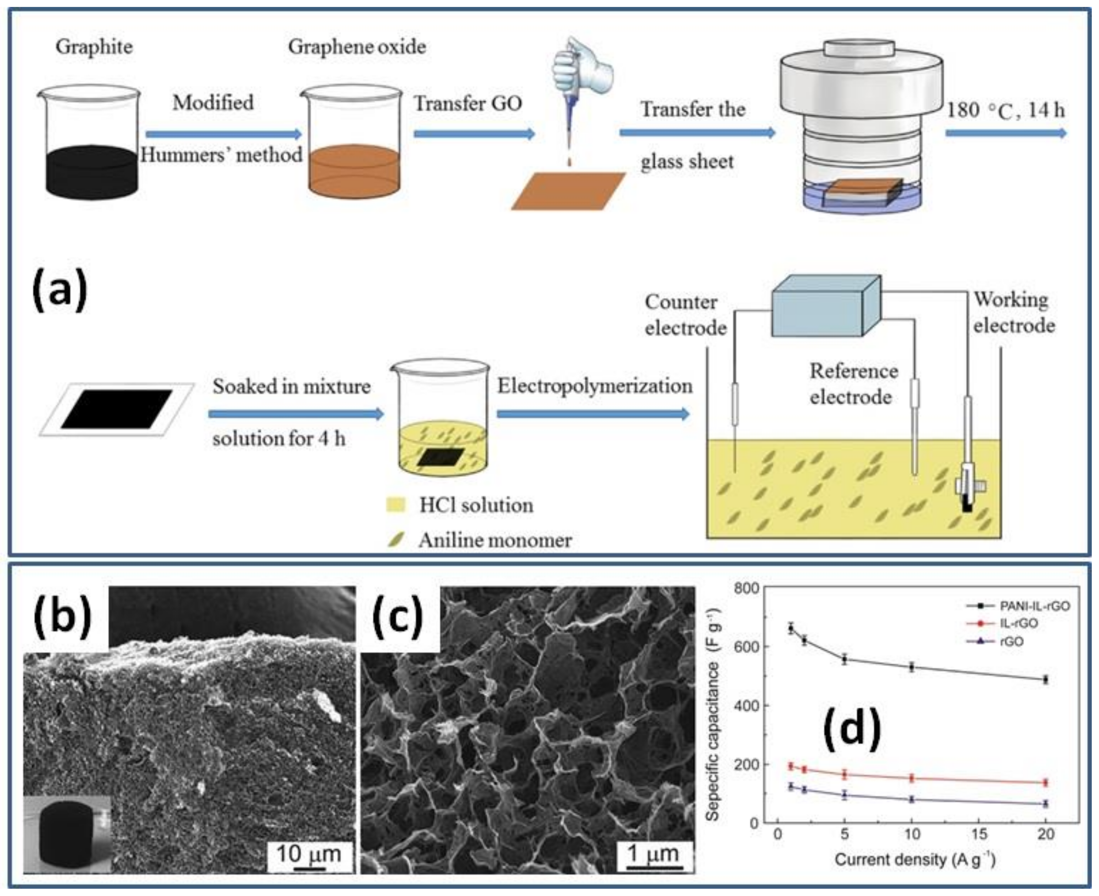
Porous sponge-like rGO modified by ionic liquid (IL) was prepared by the HT method and freeze-dried for the following PANI deposition by EP (Figure 8b,c) [62]. For the nucleation and growth of PANI nanorods, a IL-rGO electrode was immersed into a 1.0 M H2SO4 electrolyte containing 0.05 M aniline monomer and constant potential of 0.8 V was applied for 60 s at constant current density of 2 mA/cm2 (Figure 8b). The nanocomposite formed by in situ EP of PANI on the freestanding IL-rGO electrode was shown to consist of the pore walls of the IL-rGO sponge entirely covered by the coral-like PANI. Prepared hybrid material had a high specific capacitance of 662 F/g at 1 A/g, much higher than the reported capacitance for rGO and IL-rGO (Figure 8d) [62].
Figure 8.
Illustration for the fabrication process of PANI/rGO composite hydrogel film (a) (Reprinted from [50], Copyright 2021, with permission of Elsevier). Microstructures of freeze-dried sponge-like IL-rGO (b) and PANI-IL-rGO nanocomposite (c). Specific capacitances of PANI-IL-rGO, IL-rGO and rGO electrodes versus discharge current densities (d) (Reprinted from [62], Copyright 2016, with permission of Elsevier).

Porous graphene foam (GF) obtained by HT and freeze-drying processes onto a Ni template was used for EP of PANI with a scanning voltage range of −0.5 V to +1.5 V by Wu et al. [63]. Such 3D PANI-GF on a Ni structure presented a specific capacitance of 479 F/g at 1 A/g that was much higher than the 192 F/g reported for pristine GF onto Ni [63].
Pedros et al. prepared several porous PANI-rGO electrodes using GF as a substrate and HCl, ANI and methanol (CH3OH) as electrolytes at different EP conditions including with/without stirring, pulsed/DC potential, etc. [64]. As a result, the highest specific capacitance of 968 F/g at 0.31 A/g for the final electrodes prepared under direct current (DC) potential for 540 s with stirring was reported based on the total mass of the GF/PANI material (or 1474 F/g based on the mass of PANI alone) [64].
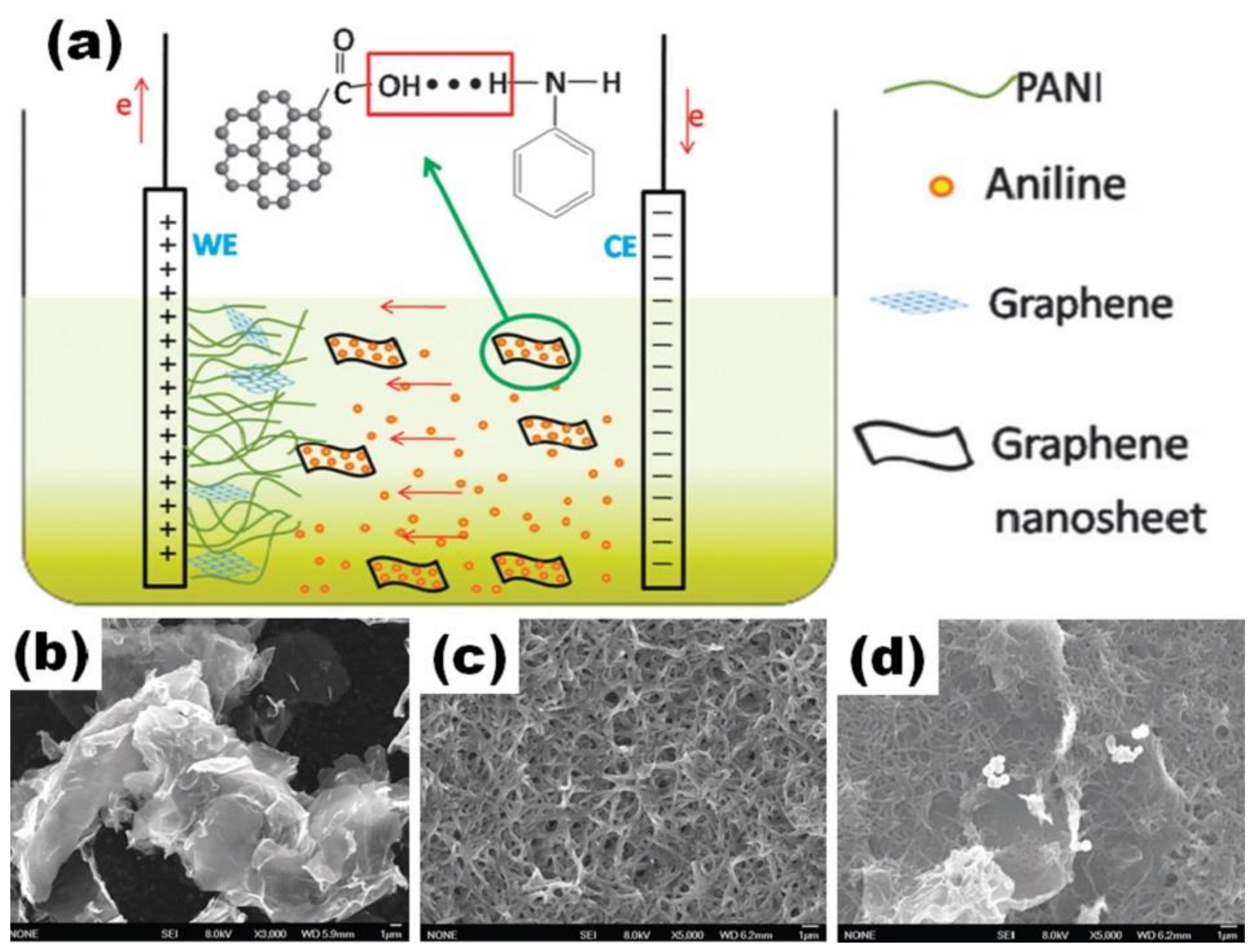
Hu et al. used ITO substrate as a working electrode and graphite as a counter electrode in a two-electrode cell (Figure 9a) for the preparation of PANI/rGO films by electrochemical polymerization from electrolyte containing HNO3, graphene, n-hexane, h-hexane and TritonX-100 [65]. PANI/rGO film was obtained after the combination of rGO (Figure 9b) and PANI (Figure 9c) and electrochemical polymerization that was performed through a pulse galvanostatic current process at a mean current density of 1 mA/m2 (Figure 9d). Graphene nanosheets were embedded into PANI, suggesting graphene interconnection with the polymer. The specific capacitance of 878 F/g at 1 A/g was reported for the prepared PANI/rGO film on ITO [65].
Figure 9.
Scheme of the in situ electrochemical polymerization process of the nanorod-PANI–Graphene composite film (a). Microstructure of graphene (b), nanorod PANI film (c) and PANI–Graphene composite film (d) (Reprinted from [65] with permission of RSC Publishing).
Figure 9.
Scheme of the in situ electrochemical polymerization process of the nanorod-PANI–Graphene composite film (a). Microstructure of graphene (b), nanorod PANI film (c) and PANI–Graphene composite film (d) (Reprinted from [65] with permission of RSC Publishing).

A slightly lower specific capacitance of 640 F/g at 100 mV/s was reported by Feng et al. for mixed PANI/rGO film deposited on ITO substrate as a working electrode in a three-electrode cell. Using Pt as a counter electrode and a saturated calomel electrode (SCE) as a reference electrode, the EP process was performed by scanning the potential of the electrodes between −1.3 V and +1.0 V at 50 mV/s in the mixed electrolyte including GO (with the following reducing), ANI and H2SO4 [66]. A high cycling stability of 90% after 1000 cycles at 0.1 A/g was reported for SC made of these films [66].
Thus, it can be concluded that during electrochemical polymerization, PANI molecules are electronegatively and the surface of graphene network is positively charged, and they can form both layered and mix structures. The EP of PANI can be performed at constant applied electric potential, with the optimal potential value of 0.8 V according to Lv et al. [48].
Based on a few works mentioning the amount of PANI in the final electrode (see Table 1, Table 2 and Table 3), the specific capacitance as well as cycling stability of PANI/graphene electrodes are not strongly dependent on the PANI content. However, the value of the specific capacitance can vary, for example, with the time of the polymerization process [45,46,48,50,52,56,57], the process cycling number that forms the PANI layer number [49,60], charge loading [46,65] and applied current density during EP [47].
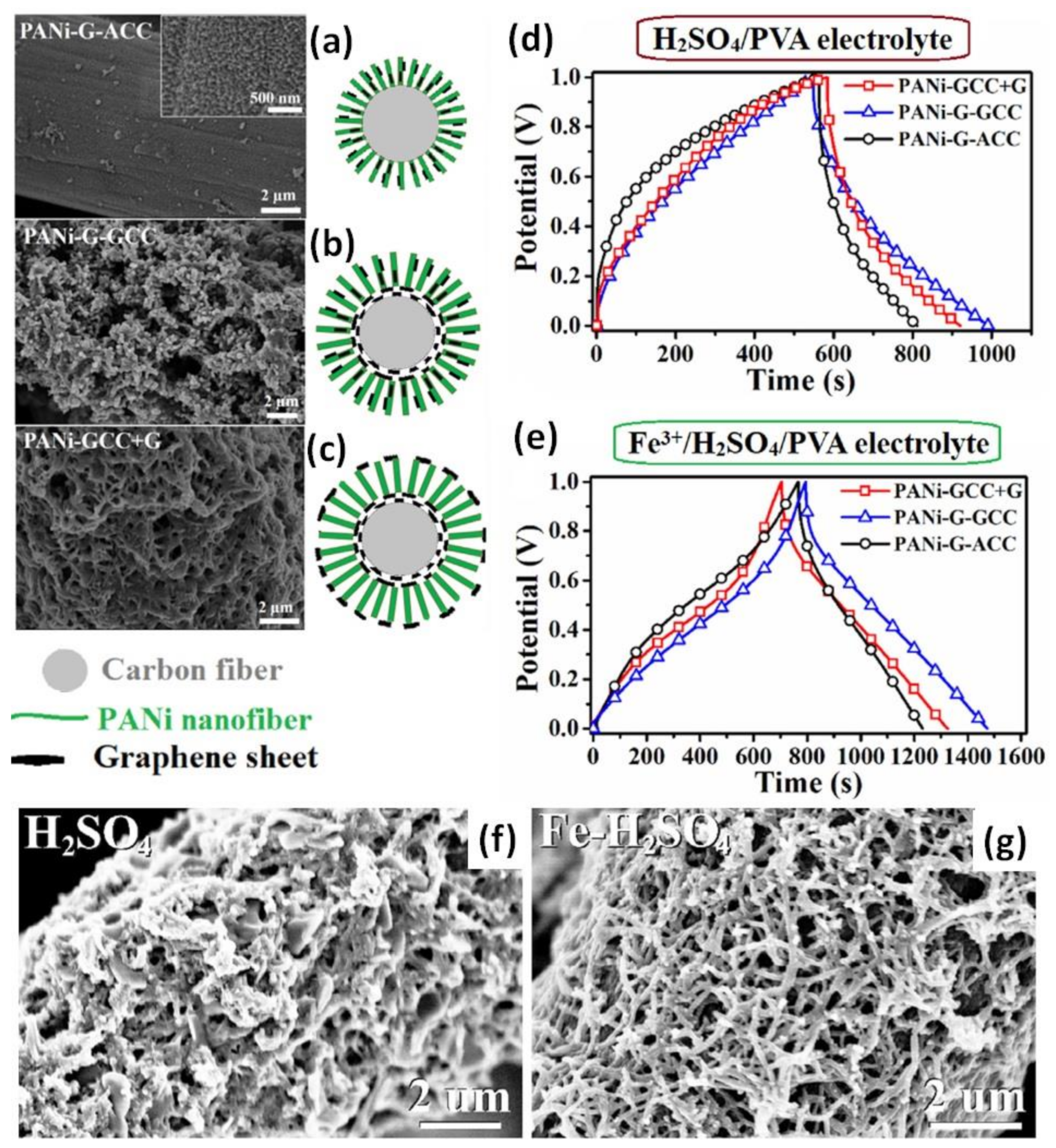
At the same time, a relationship between the structure of PANI/rGO composite and the electrochemical properties of the composite electrode was also reported by Liu et al. [67]. Three kinds of PANI with graphene on carbon cloth (CC) electrodes with different spatial distribution of graphene sheets depicted in Figure 10 were fabricated by the electrochemical approach. First, the electrode was fabricated by electrochemical deposition of PANI and graphene onto the surface of CC (PANI-G-ACC), as shown in Figure 10a. Second, the exfoliated graphene sheets in a Li2SO4 solution were firstly deposited onto CC by cyclic voltammetry and then the electrode was prepared by depositing PANI and graphene on the modified CC (PANI-G-GCC), as shown in Figure 10b. Third, after the exfoliated graphene was also firstly deposited on the CC, a PANI layer was grown on the modified CC, using 0.5 M H2SO4 solution containing 0.2 M aniline and the electrochemical polymerization method, and then exfoliated graphene was again deposited on top of PANI resulting in the PANI-GCC+G structure presented in Figure 10c.
Figure 10.
SEM images (left) and schematic view (right) for three kinds of PANI with graphene on carbon cloth with different spatial distribution of graphene sheets: aniline was mixed with graphene oxide before electropolymerization onto carbon cloth (PANI-G-ACC) (a), PANI was polymerized onto carbon cloth with already deposited graphene (PANI-G-GCC) (b) and additional graphene was deposited onto already prepared PANI/rGO/CC (PANI-GCC+G) (c). GCD curves at the current density of 5 mA/cm2 for the supercapacitors assembled with three kinds of the composite electrodes by using H2SO4/PVA (d) and Fe3+/H2SO4/PVA electrolytes (e) (Reprinted from [67], Copyright 2022, with permission of Elsevier). SEM images for PANI on CC with already deposited graphene tested after 3000 cycles in the electrolyte without (f) and with 15 mol. % Fe3+ ion content (g) (Reprinted from [68], Copyright 2020, with permission of Elsevier).

The electrodes were stable during the measurements in 1 M H2SO4 electrolyte and along with the rise of the current density from 5 mA/cm2 to 30 mA/cm2, the areal capacitances decreased from 3.78 to 3.01, from 4.52 to 3.87 and from 3.96 F/cm2 to 3.19 F/cm2, for PANI-G-ACC, PANI-G-GCC and PANI-GCC+G, respectively. The capacitance retention was 79.6%, 85.7% and 80.5%, respectively. Thus, the spatial distribution of graphene sheets relating to the arrays corresponding to PANI-G-GCC structure (shown in Figure 10b) was reported to be slightly superior compared to the other two. Moreover, symmetric SCs prepared with electrolyte H2SO4/PVA (Figure 10d) have shown a more deformed GCD curve in comparison to the almost triangular GCD of SCs with Fe3+/H2SO4/PVA electrolyte (Figure 10e). Resulted areal capacitances varied approximately twofold: from 0.78 F/cm2 in H2SO4/PVA to 1.79 F/cm2 in Fe3+/H2SO4/PVA electrolyte for PANI-G-ACC, from 1.13 F/cm2 in H2SO4/PVA to 2.26 F/cm2 in Fe3+/H2SO4/PVA electrolyte for PANI-G-GCC, and from 0.95 F/cm2 in H2SO4/PVA to 2.05 F/cm2 in Fe3+/H2SO4/PVA electrolyte for PANI-GCC+G reported at 5 mA/cm2. At the same time, the cycling stability of all SCs was found to be similar in both electrolytes, for example, 92.3% and 92.7% for PANI-G-GCC in H2SO4/PVA and Fe3+/H2SO4/PVA, respectively [67]. This difference is explained by the influence of Fe3+ on the morphology of the studied materials, as shown in Figure 10f,g [68].
2.4. Energy Storage in PANI/rGO Supercapacitors
The electrochemical performance of symmetric supercapacitors obtained by assembling two equal PANI/rGO electrodes was further investigated in some of the works mentioned above. Although the goal of SC research is to achieve high energy density (in Wh/cm3) at high power density (in W/cm3), these values are rarely presented in the available publications. Often, they are substituted by SC specific energy (E in Wh/kg) and power (P in W/kg), which are calculated using the following expressions:
where Ctotal and Csingle el. are the measured capacitance of the full SC and the single electrode, respectively, ∆V is the operating voltage window and Δt is the discharge time in hours. Thus, although the values of capacitance are very important for the SC performance, the electrolyte voltage window also plays a major role for the enhancement of specific energy as well as specific power. In summary, Table 1, Table 2 and Table 3 include E and p values as the main characteristics for the reported symmetric capacitors made of PANI/rGO-based electrodes together with parameters such as the electrolyte type and its potential window.
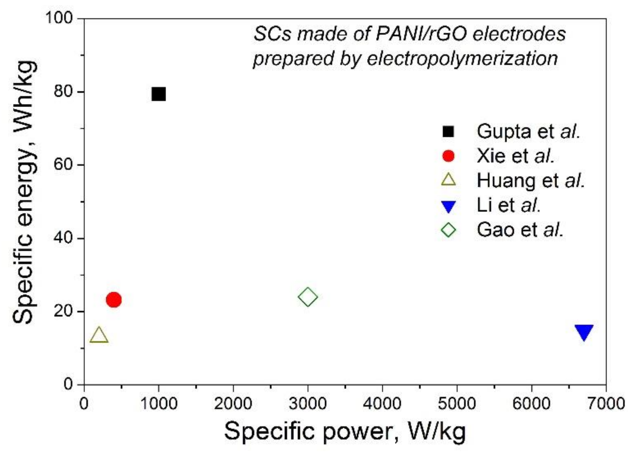
The electrolyte for the reported PANI-rGO-based SCs can be solid, such as H2SO4 or H3PO4, with PVA having similar potential windows up to 1 V. The specific capacitance of such a full device was reported to be as much as 973 F/g (at 2 A/g) for planar SC on PANI/rGO [55]. Since the specific power of supercapacitors is typically higher than that of batteries, the main interest is the value of the specific energy. As can be seen from Table 1, Table 2 and Table 3, today, the highest value of the specific energy can reach 79.4 Wh/kg for SC with electrodes of one ErGO/PANI bi-layer measured in H2SO4 from −0.2 to +0.6 V [60]. That is higher than the 62.2 Wh/kg reported for PANI/rGO [69] mentioned as the highest value among SCs with PANI/rGO electrodes prepared by the chemical oxidative method [30]. At the same time, SCs with PANI/rGO electrodes prepared by EP on rGO paper [44], on GH pressed onto carbon cloth [57], on GPT [53] or on G obtained with wavy-shaped Ni as the template [51] presented specific energy <25 Wh/kg, as shown in Figure 11. Thus, currently the performance of a structure consisting of a single PANI/rGO bi-layer with rGO on top looks more promising than that of structures with PANI on top or mixed structures, although for a reliable conclusion, all these structures should be studied under the same conditions. Regarding the main mechanisms behind that, the two-dimensional planar structure of graphene sheets was stated to be beneficial to homogeneous nucleation of a large amount of polymer, giving rise to a higher areal density of electroactive sites and chemically bridged interfaces for redox reactions, while the planar contact area between rGO and PANI supports constructing a conductive network with a higher electron transfer rate and lower resistance [60].

3. Processing Conditions during Electropolymerization of PANI
3.1. Time of Electropolymerization Process
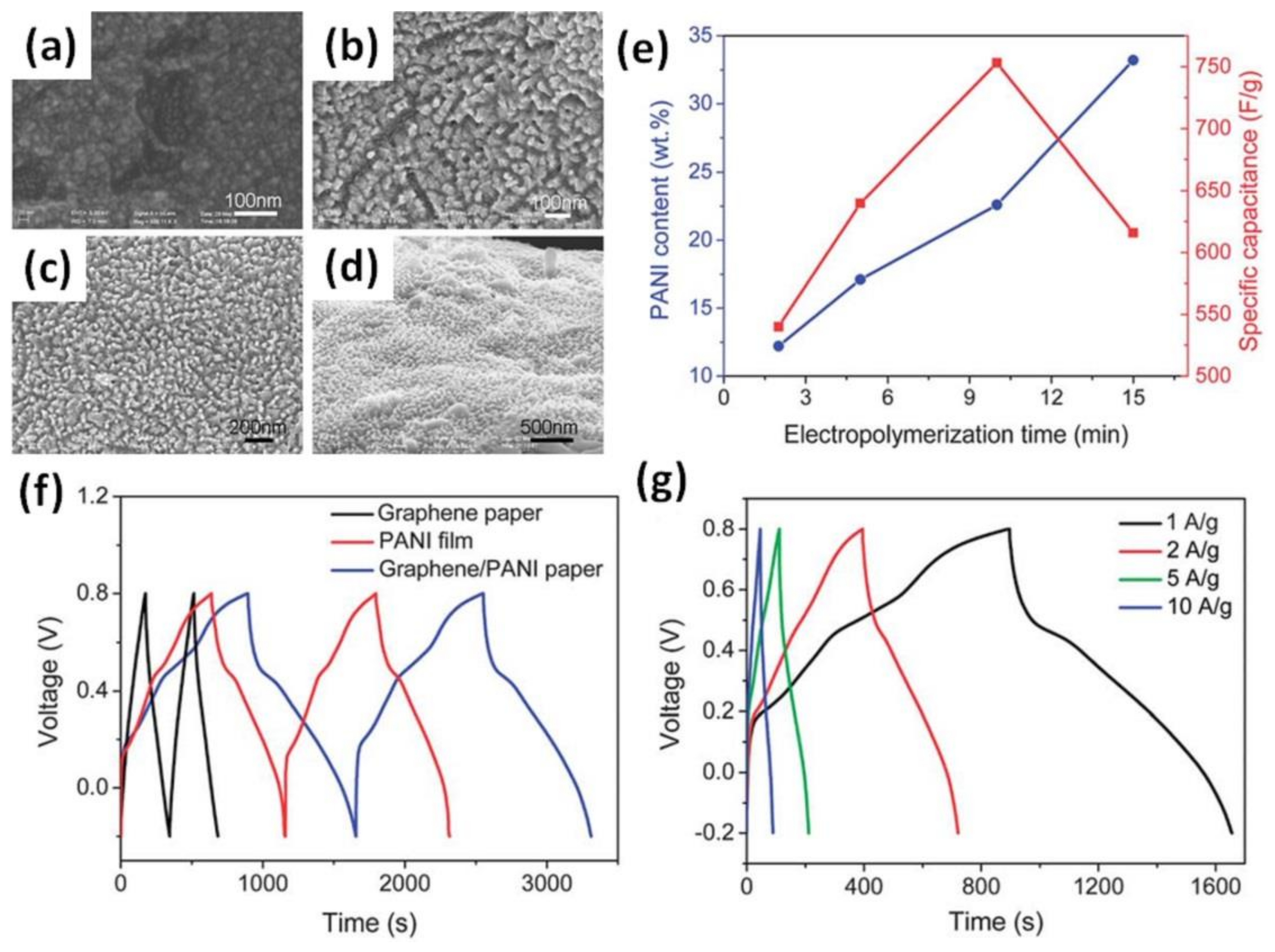
PANI can be electropolymerized for different time intervals (from a few seconds to several hours) and that results in different morphology. As shown in Figure 12a–d, a PANI layer deposited on graphene paper at a potential of 0.8 V from 2 min to 15 min has a different surface as well as PANI content in the composite (Figure 12e) [45]. The maximum specific capacitance of 508 F/g was obtained for a PANI/rGO electrode deposited for 10 min, corresponding to 22.3 wt% PANI (Figure 12e). Moreover, Figure 12f shows that the galvanostatic charge–discharge curve (GCD) of pristine graphene paper has an ideal triangular form [45] that is typical for EDLC [14]. At the same time, the GCD of pristine PANI, being far from an ideal triangular shape and showing some “plateau” similar to that of battery-type materials, presented obvious pseudocapacitance behaviour. The strong impact of pseudocapacitance can also be found in the GCD of the layered PANI/rGO electrode presented in Figure 12g [45].
Figure 12.
Microstructures of the surface of the graphene/PANI composite papers with EP times of: 2 min (a), 5 min (b), 10 min (c) and 15 min (d). Changes of weight content of PANI in the graphene–PANI papers and the corresponding specific capacitances with EP time (e). Galvanostatic charge–discharge curves of graphene paper, PANI film on the Pt electrode and graphene–PANI paper at a current density of 1 A/g (f) and GCD curves of graphene–PANI paper at different current densities (g) (Reprinted from [45] with permission of RSC Publishing).

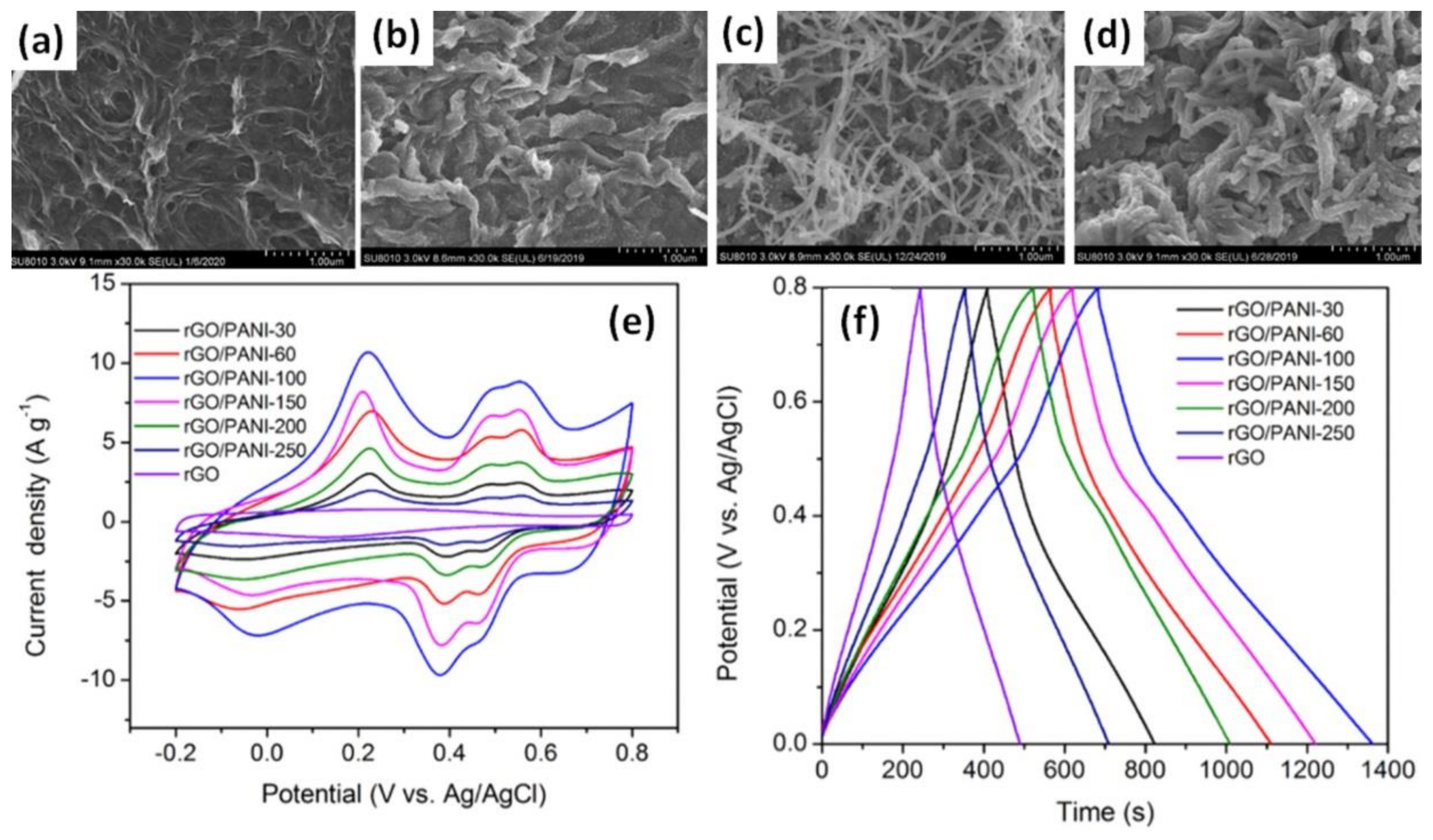
In the case of more porous rGO hydrogel (GH) film, just 100 s (less than 2 min) at a potential of +0.75 V were enough to create a GH/PANI electrode from HCl with ANI electrolyte with the highest specific capacitance of 853 F/g [57]. It is obvious from Figure 13a–d that higher polymerization time results in higher PANI content (thicker PANI fibre). Moreover, as can be seen in Figure 13e, the specific capacitance that corresponds to the area of the cyclic voltammogram decreased after increasing, when the deposition time was more than 100 s. Moreover, although redox peaks are strong in CV curves, the parameter b ~0.9 was calculated by Liu et al. as a slope of logarithm of CV peak current density versus scan rate [57]. That proximity to 1 corresponds to dominant capacitive behaviour of the mixed PANI-rGO electrode, whereas battery-type materials are characterized by b = 0.5 [14]. Moreover, the obvious triangular GCD reported by Liu et al. in Figure 13f also supports the capacitive type of these mixed PANI-rGO structures that slightly differs from the GCD observed in the layered PANI/rGO structures mentioned above [45,49,53].
Figure 13.
Microstructures of pristine rGO (a) and after PANI electropolymerization onto/into rGO hydrogel for 30 s (rGO/PANI-30) (b), 100 s (rGO/PANI-100) (c) and 200 s (rGO/PANI-200) (d) samples deposited. CV curves at a scan rate of 5 mV/s for the rGO and various rGO/PANI electrodes after different times of electropolymerization (30, 60, 100, 150, 200 and 250 s) (e). GCD curves at different current densities for rGO/PANI-100 electrode (f) (Reprinted from [57], Copyright 2021, with permission of Elsevier).

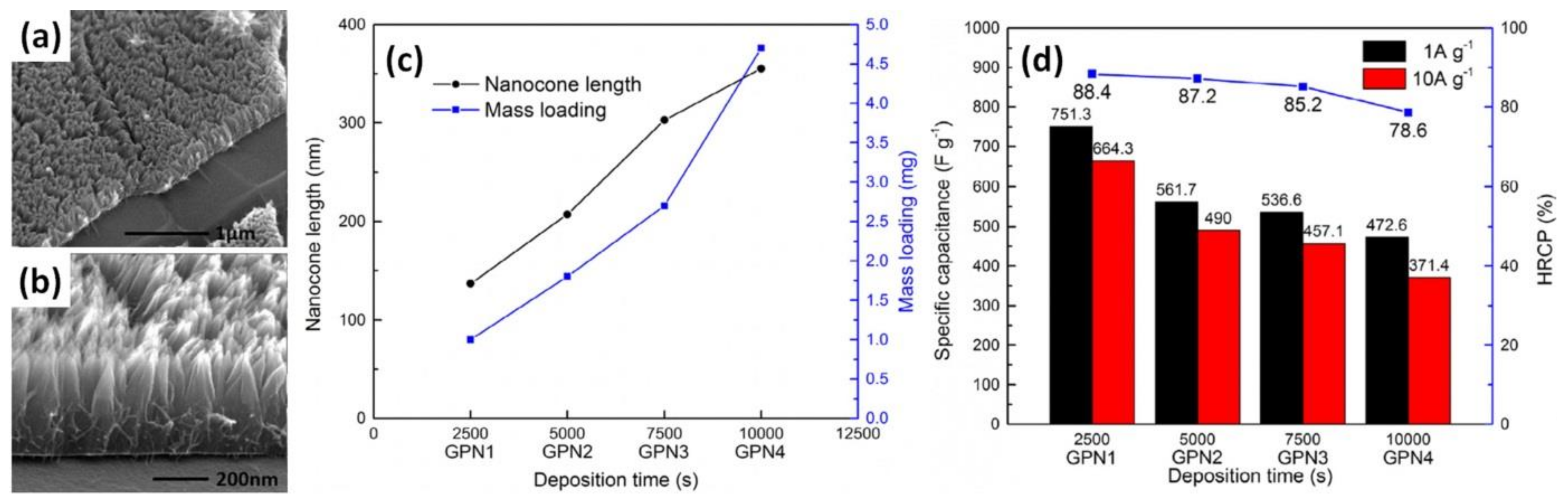
The porous graphene foams (or graphene frameworks) (GF) were also mentioned above, to be used as supports for EP of PANI to obtain a layered graphene–PANI network (GPN) structure. Yu et al. found that the mass and length of PANI nanocones deposited at an anodic current density of 0.1 A/g on porous GF (Figure 14a,b) increase with an increase in deposition time (2500, 5000, 7500 and 10,000 s correspond to GPN1, GP2, GP3 and GP4, respectively), as shown in Figure 14c [50]. This is inversely proportional to the measured specific capacitance, reaching 472 F/g at 1 A/g for the longest deposition of 10,000 s (~2.8 h) and 751 F/g at 1 A/g for the shortest EP time of 2500 s (~42 min), as shown in Figure 14d [50].
Figure 14.
Microstructure of vertically aligned PANI nanocone arrays on the surface of 3D graphene (a,b). Mass loading of PANI and length of nanocones vs. electrodeposition time (c). Specific capacitance and high-rate capacitance percentage (HRCP) of GPN1-4 (d) (Reprinted from [50], Copyright 2015, with permission of Elsevier).

At the same time, much higher specific capacitance of 968 F/g (normalized by the mass of the full GF/PANI composite) was reported by Pedros et al. for the GF-PANI electrode electrodeposited at 0.8 V and stirring for 9 min [64]. Moreover, Pedros et al. found that the polymerization of GF/PANI at the same potential of 0.8 V but without stirring or at a pulsed potential of 0.8 V with stirring for 9 min leads to lower values of specific capacitance [64].
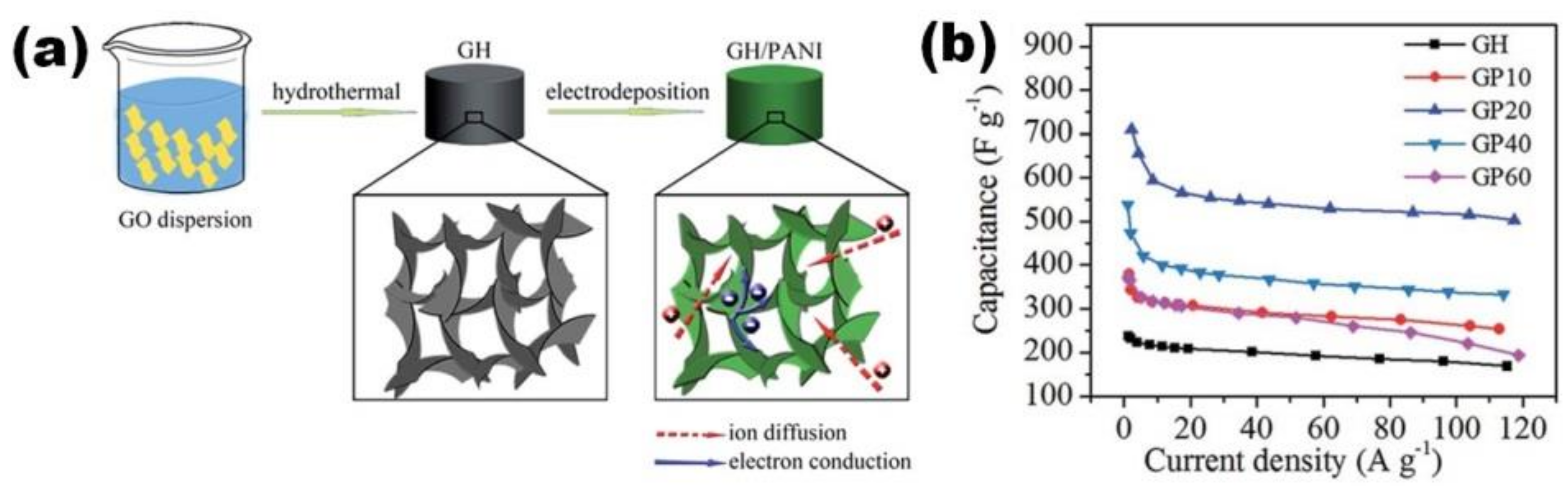
PANI-rGO electrodes with mixed structure were prepared by Gao et al. with preliminary immersion of graphene hydrogel (GH) into the electrolyte for several hours before polymerization (Figure 15a) and with EP at a potential of 0.8 V for 10–60 s only [56]. The obtained graphene with PANI (GP) electrodes presented the highest specific capacitance of 710 F/g at 2 A/g for EP time of 20 s and PANI content of 29 wt%, while longer time did not increase the specific capacitance (Figure 15b). Although 60 s of polymerization process resulted in the deposition of 50 wt% PANI, the formation of PANI on GH was reported to result in a monotonic decrease of specific surface area (SSA) from 305 m2/g for pristine GH to 105 m2/g for 60 s EP PANI/GH [56].
Figure 15.
Schematic illustrating the fabrication process toward GH/PANI (GP) composite and 3D ion and electron transport pathway in porous GH/PANI electrode (a). Plots of specific capacitance versus discharging current density for GH/PANI composites prepared for different times of PANI electropolymerization (10, 20, 40 and 60 s, respectively) compared with GH electrode (b) (Reprinted from [56] with permission of RSC Publishing).

Zang et al. used EP time from 2 min to 15 min to obtain hybrid films consisting of graphene woven fabric (GWF) and PANI (Figure 16a) [52]. The morphology was found to be different before and after EP according to scanning electron microscopy images presented in Figure 16b,c, respectively. As shown in Figure 16d, the coverage of PANI expanded with the time increase. The PANI form was found to change from strip-like to needle-like when the EP time reached 30 min. The optimal EP time to obtain a granular aggregated structure of PANI was 15 min, which can be supported by the highest areal capacitance of 23 mF/cm2 calculated based on GCD (presented in Figure 16e) for a symmetric SC [52].
Figure 16.
Illustration of the preparation and fabrication process for the GWF with PANI supercapacitor (a). Microstructures of GWF (b) and GWF +PANI films (c). Schematic illustrations and microstructures of the GWFs coated with PANI at different electropolymerization times (2, 5, 15 and 30 min, respectively) (d). Galvanostatic charge/discharge curves of GWF+PANI (Current density: 0.1 mA/cm2) (e) (Reprinted from [52] with permission of RSC Publishing).

3.2. Cycling Number and Current Density
Wu et al. reported that the PANI content was dependent on the cycling number [49]. In that work, GH was preliminary pressed into disk form and electrochemical deposition of PANI started immediately after the disk was immersed into the electrolyte to avoid the diffusion of the monomer aniline into the GH disk (Figure 17a). A porous PANI fibre layer (Figure 17b) was observed on pressed graphene multilayers (Figure 17c). PANI content increased with the cycling number, with 60 wt% PANI found to be the optimal concentration for such PANI-capsulated GH electrodes (Figure 17d) [49].
Direct electrochemical growth of polyaniline nanowire arrays (PANI NWAs) on surfaces of graphene sheets in partially exfoliated graphite foil (Ex-GF) was achieved by Ye at al. at different current densities (from 0.2 mA/cm2 to 1 mA/cm2), for different time intervals (from 45 min to 6 h) and with different aniline concentrations (from 50 mM to 500 mM) [46]. The highest specific capacitance of 840 F/g, among the electrodes prepared at the same current density of 0.5 mA/cm2, for the same time of 1.5 h, was obtained for the composite made from the electrolyte with HCl and the lowest ANI concentration of 50 mM. On the other hand, when the concentration of ANI and current density were fixed at 100 mM and 0.5 mA/cm2, respectively, a longer deposition time resulted with a decrease of the specific capacitance from 738 F/g for 1.5 h to 645 F/g for 3 h deposition [46].
Figure 17.
Schematic image illustrating pressed GH/PANI electrode (a). Microstructures of the PANI cap layer (b) and GH matrix (c). Specific capacitance as a function of PANI content (d) (Reprinted from [49] with permission of Wiley).
Figure 17.
Schematic image illustrating pressed GH/PANI electrode (a). Microstructures of the PANI cap layer (b) and GH matrix (c). Specific capacitance as a function of PANI content (d) (Reprinted from [49] with permission of Wiley).

3.3. Charge Loading/Charge Density Effect
The effect of the charge loading on the specific capacitance of mixed PANI/rGO film prepared by the pulse galvanostatic current process on ITO substrate was analysed by Hu et al. [65]. The specific capacitance decreased with the charge loading increase, from 725 F/g at low 0.5 C to 317 F/g at high 4 C. Hu et al. mentioned that thinner PANI/rGO film obtained at 0.5 C has highly porous microstructure in opposition to thicker film that hinders the electrochemical accessibility between the film and the electrolyte [65].
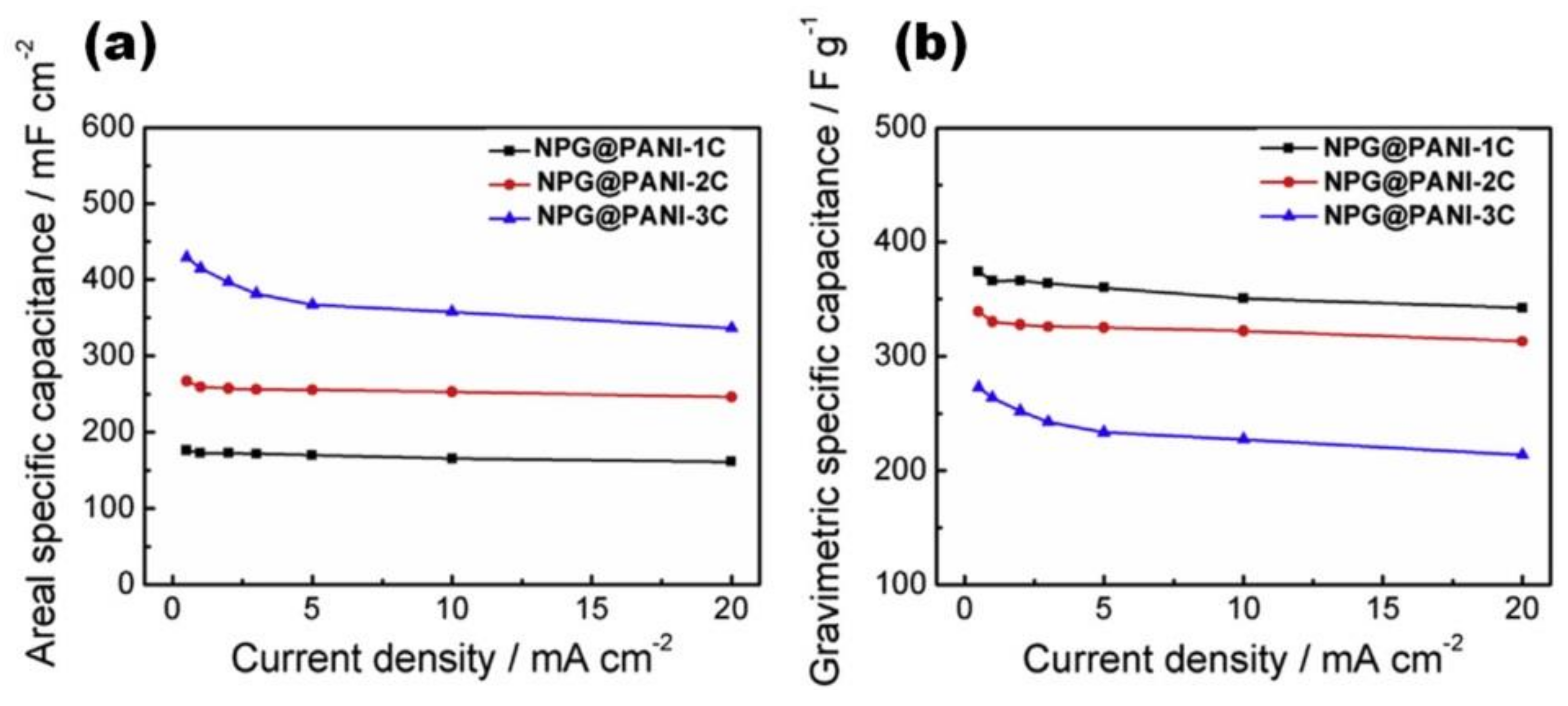
Jin et al. studied vertically aligned polyaniline nanocones prepared at different EP charge densities on nitrogen-doped porous graphene (NPG) film. When the polymerization charge density increases from 1 C/cm2 to 3 C/cm2, the specific capacitance decreases from ~440 F/g to 294 F/g at 1 A/cm2, although the specific (gravimetric) capacitance and areal capacitance show the reverse variation trends (Figure 18) [47].
Figure 18.
Electrochemical performance of NPG@PANI films with various polymerization charge densities measured by a three-electrode method in 1 M Et4NBF4-AN electrolyte: areal specific capacitances as a function of various current densities (a) and gravimetric specific capacitances as a function of various current densities (b) (Reprinted from [47], Copyright 2019, with permission of Elsevier).

4. Conclusions and Perspective
In this review, we presented research progress on the preparation of PANI by the electropolymerization process to obtain PANI/graphene or reduced graphene electrodes for electrochemical energy storage. Although pristine PANI is environmentally friendly and has high electric conductivity and high flexibility, it has also poor cycling stability. Thus, studies of the synergetic effect between PANI and graphene are currently of great interest. At the same time, deep investigations of the in situ electropolymerized graphene–PANI electrodes without extra additives (which are typically observed for commercial electrodes made from powder materials) are crucial. However, a number of the available analyses of PANI/rGO electrodes prepared by electropolymerization are very limited despite the visible improvements of the electrochemical properties of both graphene (significant increase of the specific capacitance) and PANI (high cycling stability). Moreover, different types of electrodes can be obtained by electropolymerization by simply varying the components of the electrolyte: (i) only aniline monomer and acid resulted in layered PANI/rGO electrode; (ii) rGO added to the electrolyte, together with aniline monomer and acid or porous structure of the carbonaceous substrate, resulted in a mixed PANI-rGO electrode. Nanocomposite electrode encapsulation by rGO has also been shown to be an advantage for electrode performance. However, it must be stressed that important information including PANI content or mass loading, as well as cycling stability of the final electrode, is sometimes missing in the available literature.
Thus, future research should focus on the development of the properties of PANI/rGO nanostructures as electrodes for supercapacitors with enhanced performance. In addition, preparation of PANI/rGO (as well as functionalized PANI/functionalized graphene) by the electropolymerization method for application in rechargeable batteries needs to be deeply explored, especially in flexible and wearable batteries due to the high flexibility of the PANI/rGO composite. Moreover, although several relationships between the time, cycling number, current density, charge loading/density effect during the EP process of PANI and the composite electrochemical properties have been reported, more complex and deeper studies on the preparation of layered PANI/rGO as well as PANI-rGO as promising electrode materials for energy storage devices are necessary in the future.
Author Contributions
Data analysis, O.O. and A.T.; writing—original draft preparation, O.O. and A.T.; writing—review and editing, O.O. and A.T. All authors have read and agreed to the published version of the manuscript.
Funding
This work was supported by national funds, through FCT (Fundacao para a Ciencia e a Tecnologia) in the scope of the framework contract foreseen in numbers 4, 5 and 6 of article 23 of the Decree Law 57/2016, of 29 August, UIDB/00481/2020 and UIDP/00481/2020; and CENTRO-01-0145-FEDER-022083—Centro Portugal Regional Operational Programme (Centro2020), under the PORTUGAL 2020 Partnership Agreement, through the European Regional Development Fund and developed within the scope of the project CICECO-Aveiro Institute of Materials, UIDB/50011/2020, UIDP/50011/2020 and LA/P/0006/2020, financed by national funds through the FCT/MEC (PIDDAC) and within FCT independent researcher grant 2021.02284.CEECIND.
Institutional Review Board Statement
Not applicable.
Informed Consent Statement
Not applicable.
Data Availability Statement
No new data were created or analysed in this study. Data sharing is not applicable to this article.
Conflicts of Interest
The authors declare no conflict of interest.
Glossary
| 2-el. syst. | two-electrode system |
| ANI | Aniline |
| BMIMBF4 | 1-Butyl-3-methylimidazolium tetrafluoroborate |
| CC | carbon cloth |
| CNT | carbon nanotubes |
| CSA | camphorsulphonic acid |
| CVD | chemical vapour deposition |
| DMF | dimethylformamide |
| ErGO | electrochemically reduced GO |
| Et4NBF4 | tetraethylammonium tetrafluoroborate |
| Ex-GF | partially exfoliated graphite foil |
| G | Graphene |
| GH | graphene hydrogel |
| GO | graphene oxide |
| GP | graphene paper |
| GWF | graphene woven fabric |
| G/PT | graphene-coated polyester textile |
| HbG | hydrogen-bonded graphene |
| HT | hydrothermal method |
| IL | ionic liquid |
| ITO | indium tin oxide |
| NF | nickel foam |
| PAH | poly(allylamine hydrochloride) |
| PANI-NFS | polyaniline-nanofiber sponge |
| PDMS | polydimethylsiloxane |
| rGO | reduced graphene oxide |
| SDS | sodium dodecyl sulphate |
| TEM | transmission electron microscopy |
| VF | vacuum filtration |
References
- Sumangala, T.P.; Sreekanth, M.S.; Rahaman, A. Applications of Supercapacitors. In Handbook of Nanocomposite Supercapacitor Materials III. Springer Series in Materials Science; Kar, K.K., Ed.; Springer: Cham, Switzerland, 2021; Volume 313, pp. 367–393. [Google Scholar] [CrossRef]
- Yu, A.; Chabot, V.; Zhang, J. Electrochemical Supercapacitors for Energy Storage and Delivery: Fundamentals and Applications, 1st ed.; CRC Press: Boca Raton, FL, USA, 2013; pp. 1–373. [Google Scholar] [CrossRef]
- Hou, H.; Qiu, X.; Wei, W.; Zhang, Y.; Ji, X. Carbon anode materials for advanced sodium-ion batteries. Adv. Energy Mater. 2017, 7, 1602898. [Google Scholar] [CrossRef]
- Faraji, S.; Ani, F.N. The development supercapacitor from activated carbon by electroless plating—A review. Renew. Sust. Energy Rev. 2015, 42, 823–834. [Google Scholar] [CrossRef]
- Zhang, W.; Cheng, R.-R.; Bi, H.-H.; Lu, Y.H.; Ma, L.-B.; He, X.-J. A review of porous carbons produced by template methods for supercapacitor applications. New Carbon Mater. 2021, 36, 69–81. [Google Scholar] [CrossRef]
- Ke, Q.; Wang, J. Graphene-based materials for supercapacitor electrodes—A review. J. Materiom. 2016, 2, 37–54. [Google Scholar] [CrossRef] [Green Version]
- Zhang, P.; Li, Z.; Zhang, S.; Shao, G. Recent advances in effective reduction of graphene oxide for highly improved performance toward electrochemical energy storage. Energy Environ. Mater. 2018, 1, 5–12. [Google Scholar] [CrossRef] [Green Version]
- Okhay, O.; Krishna, R.; Guerra, L.M.; Ventura, J.; Titus, E.; Gracio, J. Influence of oxidation and deposition process on electrical properties of graphene films. J. Mater. Sci. Eng. B 2014, 4, 318–321. [Google Scholar] [CrossRef] [Green Version]
- Presser, V.; Heon, M.; Gogotsi, Y. Carbide-derived carbons—From porous networks to nanotubes and graphene. Adv. Funct. Mater. 2011, 21, 810–833. [Google Scholar] [CrossRef]
- Canal-Rodríguez, M.; Menéndez, J.A.; Arenillas, A. Performance of carbon xerogel-graphene hybrids electrodes in aqueous supercapacitors. Electrochim. Acta 2018, 276, 28–36. [Google Scholar] [CrossRef]
- Zhu, S.; Ni, J.; Li, Y. Carbon nanotube-based electrodes for flexible supercapacitors. Nano Res. 2020, 13, 1825–1841. [Google Scholar] [CrossRef]
- Okhay, O.; Tkach, A.; Gallo, M.J.H.; Otero-Irurueta, G.; Mikhalev, S.; Staiti, P.; Lufrano, F. Energy storage of supercapacitor electrodes on carbon cloth enhanced by graphene oxide aerogel reducing conditions. J. Energy Storage 2020, 32, 101839. [Google Scholar] [CrossRef]
- Okhay, O.; Tkach, A.; Staiti, P.; Lufrano, F. Long term durability of solid-state supercapacitor based on reduced graphene oxide aerogel and carbon nanotubes composite electrodes. Electrochim. Acta 2020, 353, 136540. [Google Scholar] [CrossRef]
- Okhay, O.; Tkach, A. Graphene/reduced graphene oxide-carbon nanotubes composite electrodes: From capacitive to battery-type behaviour. Nanomaterials 2021, 11, 1240. [Google Scholar] [CrossRef]
- Barbieri, O.; Hahn, M.; Herzog, A.; Kötz, R. Capacitance limits of high surface area activated carbons for double layer capacitors. Carbon 2005, 43, 1303–1310. [Google Scholar] [CrossRef]
- Shakir, I. High energy density based flexible electrochemical supercapacitors from layer-by-layer assembled multiwall carbon nanotubes and graphene. Electrochim. Acta 2014, 129, 396–400. [Google Scholar] [CrossRef]
- Simon, P.; Taberna, P.L.; Béguin, F. Electrical double-layer capacitors and carbons for EDLCs. In Supercapacitors: Materials, Systems, and Applications; Béguin, F., Frąckowiak, E., Eds.; Wiley-VCH Verlag GmbH & Co. KGaA: Weinheim, Germany, 2013; pp. 131–165. [Google Scholar] [CrossRef]
- Enock, T.K.; King’ondu, C.K.; Pogrebnoi, A.; Jande, Y.A.C. Status of biomass derived carbon materials for supercapacitor application. Int. J. Electrochem. 2017, 2017, 6453420. [Google Scholar] [CrossRef]
- Simon, P.; Burke, A. Nanostructured carbons: Double-layer capacitance and more. Electrochem. Soc. Interface 2008, 17, 38–43. [Google Scholar] [CrossRef]
- Surawan, T.; Priambodo, P.S. Supercapacitor based on active carbon electrode: Review. In Proceedings of the 16th International Conference on Quality in Research (QIR): International Symposium on Electrical and Computer Engineering, Padang, Indonesia, 22–24 July 2019; Institute of Electrical and Electronics Engineers (IEEE): Piscataway, NJ, USA, 2019; pp. 1–8. [Google Scholar] [CrossRef]
- Chee, W.K.; Lim, H.N.; Zainal, Z.; Huang, H.M.; Harrison, I.; Andou, Y. Flexible graphene-based supercapacitors: A review. J. Phys. Chem. C 2016, 120, 4153–4172. [Google Scholar] [CrossRef]
- Li, H.; Wang, J.; Chu, Q.; Wang, Z.; Zhang, F.; Wang, S. Theoretical and experimental specific capacitance of polyaniline in sulfuric acid. J. Power Sources 2009, 190, 578–586. [Google Scholar] [CrossRef]
- Eftekhari, A.; Li, L.; Yang, Y. Polyaniline supercapacitors. J. Power Sources 2017, 347, 86–107. [Google Scholar] [CrossRef]
- Sun, Z.; Zhang, J.; Ye, F.; Wang, W.; Wang, G.; Zhang, Z.; Li, S.; Zhou, Y.; Cai, J. Vulcanization treatment: An effective way to improve the electrochemical cycle stability of polyaniline in supercapacitors. J. Power Sources 2019, 443, 227246. [Google Scholar] [CrossRef]
- Deng, J.; Wang, T.; Guo, J.; Liu, P. Electrochemical capacity fading of polyaniline electrode in supercapacitor: An XPS analysis. Prog. Nat. Sci. Mater. Int. 2017, 27, 257–260. [Google Scholar] [CrossRef]
- Zhang, P.; Zhai, X.; Huang, H.; Zhou, J.; Li, X.; He, Y.; Guo, Z. Capacitance fading mechanism and structural evolution of conductive polyaniline in electrochemical supercapacitor. J. Mater. Sci. Mater. Electron. 2020, 31, 14625–14634. [Google Scholar] [CrossRef]
- Wang, Y.; Chu, X.; Zhu, Z.; Xiong, D.; Zhang, H.; Yang, W. Dynamically evolving 2D supramolecular polyaniline nanosheets for long-stability flexible supercapacitors. Chem. Eng. J. 2021, 423, 130203. [Google Scholar] [CrossRef]
- Wang, H.; Lin, J.; Shen, Z.X. Polyaniline (PANi) based electrode materials for energy storage and conversion. J. Sci. Adv. Mater. Dev. 2016, 1, 225–255. [Google Scholar] [CrossRef] [Green Version]
- Huang, Z.; Li, L.; Wang, Y.; Zhang, C.; Liu, T. Polyaniline/graphene nanocomposites towards high-performance supercapacitors: A review. Compos. Commun. 2018, 8, 83–91. [Google Scholar] [CrossRef]
- Okhay, O.; Tkach, A. Synergetic effect of polyaniline and graphene in their composite supercapacitor electrodes: Impact of components and parameters of chemical oxidative polymerization. Nanomaterials 2022, 12, 2531. [Google Scholar] [CrossRef]
- Zhang, F.; Cao, H.; Yue, D.; Zhang, J.; Qu, M. Enhanced anode performances of polyaniline-TiO2-reduced graphene oxide nanocomposites for lithium ion batteries. Inorg. Chem. 2012, 51, 9544–9551. [Google Scholar] [CrossRef]
- Liu, Y.; Zhang, J.; Liu, X.; Guo, J.; Pan, L.; Wang, H.; Su, Q.; Du, G. Nanosulfur/polyaniline/graphene composites for high-performance lithium-sulfur batteries: One pot in-situ synthesis. Mater. Lett. 2014, 133, 193–196. [Google Scholar] [CrossRef]
- Li, Z.-F.; Zhang, H.; Liu, Q.; Liu, Y.; Stanciu, L.; Xie, J. Novel pyrolyzed polyaniline-grafted silicon nanoparticles encapsulated in graphene sheets as Li-ion battery anodes. ACS Appl. Mater. Interfaces 2014, 6, 5996–6002. [Google Scholar] [CrossRef]
- Ding, H.; Jiang, H.; Zhu, Z.; Hu, Y.; Gu, F.; Li, C. Ternary SnO2@PANI/rGO nanohybrids as excellent anode materials for lithium-ion batteries. Electrochim. Acta 2015, 157, 205–210. [Google Scholar] [CrossRef]
- Mi, H.; Li, F.; He, C.; Chai, X.; Zhang, Q.; Li, C.; Li, Y.; Liu, J. Three-dimensional network structure of silicon-graphene-polyaniline composites as high performance anodes for lithium-ion batteries. Electrochim. Acta 2016, 190, 1032–1040. [Google Scholar] [CrossRef]
- Zhou, D.; Liu, Y.; Song, W.-L.; Li, X.; Fan, L.-Z.; Deng, Y. Three-dimensional porous carbon-coated graphene composite as high-stable and long-life anode for sodium-ion batteries. Chem. Eng. J. 2017, 316, 645–654. [Google Scholar] [CrossRef]
- Huang, R.-A.; Guo, Y.; Chen, Z.; Zhang, X.; Wang, J.; Yang, B. An easy and scalable approach to synthesize three-dimensional sandwich-like Si/polyaniline/graphene nanoarchitecture anode for lithium ion batteries. Ceram. Int. 2018, 44, 4282–4286. [Google Scholar] [CrossRef]
- Yin, L.; Dou, H.; Wang, A.; Xu, G.; Nie, P.; Chang, Z.; Zhang, X. A functional interlayer as a polysulfides blocking layer for high-performance lithium-sulfur batteries. New J. Chem. 2018, 42, 1431–1436. [Google Scholar] [CrossRef]
- Deng, S.-H.; Yuan, L.-J.; Chen, Y.-B.; Wang, B. Electrochemical synthesis and performance of polyaniline/MnO2/graphene oxide composites cathode for seawater battery. Appl. Surf. Sci. 2022, 581, 152261. [Google Scholar] [CrossRef]
- Menga, Q.; Caia, K.; Chena, Y.; Chen, L. Research progress on conducting polymer based supercapacitor electrode materials. Nano Energy 2017, 36, 268–285. [Google Scholar] [CrossRef]
- Hong, X.; Fu, J.; Liu, X.; Li, S.; Wang, X.; Dong, W.; Yang, S. Recent progress on graphene/polyaniline composites for high-performance supercapacitors. Materials 2019, 12, 1451. [Google Scholar] [CrossRef] [Green Version]
- Balqis, F.; Prakoso, B.; Hawari, N.H.; Eldona, C.; Sumboja, A. Recent development of polyaniline/graphene composite electrodes for flexible supercapacitor devices. ChemNanoMat 2022, 8, e202200151. [Google Scholar] [CrossRef]
- Wang, D.-W.; Li, W.; Zhao, J.; Ren, W.; Chen, Z.-G.; Tan, J.; Wu, Z.-S.; Gentle, I.; Lu, G.Q.; Cheng, H.-M. Fabrication of graphene/polyaniline composite paper via in situ anodic electropolymerization for high-performance flexible electrode. ACS Nano 2009, 3, 1745. [Google Scholar] [CrossRef]
- Xiao, F.; Yang, S.; Zhang, Z.; Liu, H.; Xiao, J.; Wan, L.; Luo, J.; Wang, S.; Liu, Y. Scalable synthesis of freestanding sandwich-structured graphene/polyaniline/graphene nanocomposite paper for flexible all-solid-state supercapacitor. Sci. Rep. 2012, 5, 9359. [Google Scholar] [CrossRef] [Green Version]
- Cong, H.-P.; Ren, X.-C.; Wang, P.; Yu, S.-H. Flexible graphene-polyaniline composite paper for high-performance supercapacitor. Energy Environ. Sci. 2013, 6, 1185. [Google Scholar] [CrossRef]
- Ye, Y.-J.; Huang, Z.-H.; Song, Y.; Geng, J.-W.; Xu, X.X.; Liu, X.-X. Electrochemical growth of polyaniline nanowire arrays on graphene sheets in partially exfoliated graphite foil for high-performance supercapacitive materials. Electrochim. Acta 2017, 240, 72–79. [Google Scholar] [CrossRef]
- Jin, J.; Mu, H.; Wang, W.; Li, X.; Cheng, Q.; Wang, G. Long-life flexible supercapacitors based on nitrogen-doped porous graphene@π-conjugated polymer film electrodes and porous quasi-solid-state polymer electrolyte. Electrochim. Acta 2019, 317, 250–260. [Google Scholar] [CrossRef]
- Lv, F.; Xiong, S.; Wang, X.; Chu, J.; Zhang, R.; Gong, M.; Wu, B.; Li, Z.; Zhu, C.; Yang, Z.; et al. Electrochemical fabrication of polyaniline/graphene paper (PANI/GP) supercapacitor electrode materials on free-standing flexible graphene paper. High Perform. Polym. 2021, 33, 1124–1131. [Google Scholar] [CrossRef]
- Wu, J.; Zhang, Q.; Zhou, A.; Huang, Z.; Bai, H.; Li, L. Phase-separated polyaniline/graphene composite electrodes for high-rate electrochemical supercapacitors. Adv. Mater. 2016, 28, 10211. [Google Scholar] [CrossRef]
- Yu, M.; Ma, Y.; Liu, J.; Li, S. Polyaniline nanocone arrays synthesized on three-dimensional graphene network by electrodeposition for supercapacitor electrodes. Carbon 2015, 87, 98–105. [Google Scholar] [CrossRef]
- Xie, Y.; Liu, Y.; Zhao, Y.; Tsang, Y.H.; Lau, S.P.; Huang, H.; Chai, Y. Stretchable all-solid-state supercapacitor with wavy shaped polyaniline/graphene electrode. J. Mater. Chem. A 2014, 2, 9142–9149. [Google Scholar] [CrossRef]
- Zang, X.; Li, X.; Zhu, M.; Li, X.; Zhen, Z.; He, Y.; Wang, K.; Wei, J.; Kang, F.; Zhu, H. Graphene/polyaniline woven fabric composite films as flexible supercapacitor electrodes. Nanoscale 2015, 7, 7318–7322. [Google Scholar] [CrossRef]
- Huang, D.; Zheng, Q.; Guo, K.; Chen, X. Wearable supercapacitor based on polyaniline supported by graphene coated polyester textile. Int. J. Energy Res. 2021, 45, 21403–21413. [Google Scholar] [CrossRef]
- Wu, X.; Wang, Q.; Zhang, W.; Wang, Y.; Chen, W. Enhanced electrochemical performance of hydrogen-bonded graphene/polyaniline for electrochromosupercapacitor. J. Mater. Sci. 2016, 51, 7731–7741. [Google Scholar] [CrossRef]
- Xue, M.; Li, F.; Zhu, J.; Song, H.; Zhang, M.; Cao, T. Structure-based enhanced capacitance: In situ growth of highly ordered polyaniline nanorods on reduced graphene oxide patterns. Adv. Funct. Mater. 2012, 22, 1284–1290. [Google Scholar] [CrossRef]
- Gao, S.; Zhang, L.; Qiao, Y.; Dong, P.; Shi, J.; Cao, S. Electrodeposition of polyaniline on three-dimensional graphene hydrogel as a binder-free supercapacitor electrode with high power and energy densities. RSC Adv. 2016, 6, 58854–58861. [Google Scholar] [CrossRef]
- Liu, Z.; Zhao, Z.; Xu, A.; Li, W.; Qin, Y. Facile preparation of graphene/polyaniline composite hydrogel film by electrodeposition for binder-free all-solid-state supercapacitor. J. Alloys Compd. 2021, 875, 159931. [Google Scholar] [CrossRef]
- Lin, Y.; Zhang, H.; Deng, W.; Zhang, D.; Li, N.; Wu, Q.; He, C. In-situ growth of high-performance all-solid-state electrode for flexible supercapacitors based on carbon woven fabric/polyaniline/graphene composite. J. Power Sources 2018, 384, 278–286. [Google Scholar] [CrossRef]
- Xiong, C.; Li, T.; Zhu, Y.; Zhao, T.; Dang, A.; Li, H.; Ji, X.; Shang, Y.; Khan, M. Two-step approach of fabrication of interconnected nanoporous 3D reduced graphene oxide-carbon nanotube-polyaniline hybrid as a binder-free supercapacitor electrode. J. Alloys Compd. 2017, 695, 1248–1259. [Google Scholar] [CrossRef]
- Gupta, S.; Price, C. Investigating graphene/conducting polymer hybrid layered composites as pseudocapacitors: Interplay of heterogeneous electron transfer, electric double layers and mechanical stability. Comp. Part B 2016, 105, 46–49. [Google Scholar] [CrossRef]
- Kakaei, K.; Hamidi, M.; Kakaei, N. Simultaneous electro-synthesis of polyaniline graphene nanocomposite in dilute graphene oxide as dopant and aniline by electrochemical method and its high specific capacitance. Mater. Res. Express 2019, 6, 085623. [Google Scholar] [CrossRef]
- Iessa, K.H.S.; Zhang, Y.; Zhang, G.; Xiao, F.; Wang, S. Conductive porous sponge-like ionic liquid-graphene assembly decorated with nanosized polyaniline as active electrode material for supercapacitor. J. Power Sources 2016, 302, 92–97. [Google Scholar] [CrossRef]
- Wu, L.; Hao, L.; Pang, B.; Wang, G.; Zhang, Y.; Li, X. MnO2 nanoflowers and polyaniline nanoribbons grown on hybrid graphene/Ni 3D scaffolds by in situ electrochemical techniques for high performance asymmetric supercapacitors. J. Mater. Chem. A 2017, 5, 4629–4637. [Google Scholar] [CrossRef]
- Pedrós, J.; Boscá, A.; Martínez, J.; Ruiz-Gómez, S.; Pérez, L.; Barranco, V.; Calle, F. Polyaniline nanofiber sponge filled graphene foam as high gravimetric and volumetric capacitance electrode. J. Power Sources 2016, 317, 35–42. [Google Scholar] [CrossRef]
- Hu, L.; Tu, J.; Jiao, S.; Hou, J.; Zhua, H.; Fray, D.J. In situ electrochemical polymerization of a nanorod-PANI-graphene composite in a reverse micelle electrolyte and its application in a supercapacitor. Phys. Chem. Chem. Phys. 2012, 14, 15652–15656. [Google Scholar] [CrossRef]
- Feng, X.-M.; Li, R.-M.; Ma, Y.-W.; Chen, R.-F.; Shi, N.-E.; Fan, Q.-L.; Huang, W. One-step electrochemical synthesis of graphene/polyaniline composite film and its applications. Adv. Funct. Mater. 2011, 21, 2989–2996. [Google Scholar] [CrossRef]
- Liu, Y.; Qin, Z.; Shen, Y.; Dou, Z.; Liu, N. Tuning spatial distribution of graphene sheets composited with polyaniline nanofiber array on carbon cloth towards ultrahigh areal energy density flexible supercapacitors. Carbon 2022, 186, 688–698. [Google Scholar] [CrossRef]
- Dou, Z.; Zhou, Y.; Shen, Y.; Xu, X.; Hu, S.; Yang, L.; Qin, Z. Realizing ultrahigh areal capacitance and cycle stability of polyaniline nanofiber network grown on graphene modified carbon cloth with the addition of trivalent iron ions in electrolyte. Electrochim. Acta 2020, 351, 136448. [Google Scholar] [CrossRef]
- Zhao, Z.; Liu, Z.; Zhong, Q.; Qin, Y.; Xu, A.; Li, W.; Shi, J. In situ synthesis of trifluoroacetic acid-doped polyaniline/reduced graphene oxide composites for high-performance all-solid-state supercapacitors. ACS Appl. Energy Mater. 2020, 3, 8774–8785. [Google Scholar] [CrossRef]
Publisher’s Note: MDPI stays neutral with regard to jurisdictional claims in published maps and institutional affiliations. |
© 2022 by the authors. Licensee MDPI, Basel, Switzerland. This article is an open access article distributed under the terms and conditions of the Creative Commons Attribution (CC BY) license (https://creativecommons.org/licenses/by/4.0/).
Share and Cite
MDPI and ACS Style
Okhay, O.; Tkach, A. Polyaniline—Graphene Electrodes Prepared by Electropolymerization for High-Performance Capacitive Electrodes: A Brief Review. Batteries 2022, 8, 191. https://doi.org/10.3390/batteries8100191
AMA Style
Okhay O, Tkach A. Polyaniline—Graphene Electrodes Prepared by Electropolymerization for High-Performance Capacitive Electrodes: A Brief Review. Batteries. 2022; 8(10):191. https://doi.org/10.3390/batteries8100191
Chicago/Turabian StyleOkhay, Olena, and Alexander Tkach. 2022. "Polyaniline—Graphene Electrodes Prepared by Electropolymerization for High-Performance Capacitive Electrodes: A Brief Review" Batteries 8, no. 10: 191. https://doi.org/10.3390/batteries8100191
Note that from the first issue of 2016, this journal uses article numbers instead of page numbers. See further details here.