Substructuring of a Petrol Engine: Dynamic Characterization and Experimental Validation
by
 , , ,
, , ,
Enrico Armentani
1 ,
,
Venanzio Giannella
2,*,
Roberto Citarella
2 ,
,
Antonio Parente
3 and
Mauro Pirelli
3 1
Department of Chemical, Materials and Production Engineering, University of Naples Federico II, P.le V. Tecchio, 80, 80125 Napoli, Italy
2
Department of Industrial Engineering, University of Salerno, via Giovanni Paolo II 132, 84084 Fisciano (SA), Italy
3
Fiat Chrysler Automobiles (FCA) Powertrain S.p.A., via ex Aeroporto, 80038 Pomigliano D’Arco (NA), Italy
*
Author to whom correspondence should be addressed.
Appl. Sci. 2019, 9(22), 4969; https://doi.org/10.3390/app9224969
Submission received: 22 October 2019
/
Revised: 12 November 2019
/
Accepted: 14 November 2019
/
Published: 19 November 2019
(This article belongs to the Special Issue Aeroacustic and Vibroacoustic Advancement in Aerospace and Automotive Systems)
Abstract
:In this work, the vibration behavior of a 4-cylinder, 4-stroke, petrol engine was simulated by leveraging on the Finite Element Method (FEM). A reduced modelling strategy based on the component mode synthesis (CMS) was adopted to reduce the size of the full FEM model of the engine. Frequency response function (FRF) analyses were used to identify the resonant frequencies and corresponding modes of the different FEM models, and the obtained results were compared with experimental data to get the model validation. Subsequently, modal-based frequency forced response analyses were performed to consider the loads acting during the real operating conditions of the engine. Finally, the impact on vibrations at the mounts, produced by an additional bracket connecting the engine block and gearbox, was also investigated. Both the full and reduced FEM model demonstrated and reproduced with high accuracy the vibration response at the engine mounts, providing a satisfactory agreement with the vibrations measured experimentally. The reduced modelling strategy required significantly shorter runtimes, which decreased from 24 h for the full FEM model to nearly 2 h for the reduced model.
1. Introduction
Due to the ever-increasing complexity of problem solving and the limitations of power computing, several methods have been developed, since the early days of numerical computation, to improve the efficiency of numerical simulations. Many techniques have been investigated to reduce the computational effort required to solve large static and dynamic problems. Modal analysis techniques have been developed to decouple the large set of ordinary differential equations and to minimize the effort required to solve an iteration of the equations of motion [1,2]. Substructuring methods have been developed to approximate complex big structures as a collection of smaller single components, allowing the simulation process to be performed in a sequence of intermediate computationally lighter steps. These advances proved beneficial, especially in the simulation of dynamic systems, which require the solution of equations of motion over large time intervals and with many individual time steps.
Accurately assessing the dynamic behavior of these elements requires the use of large finite element (FE) models [3,4,5,6,7] to represent the geometry in considerable detail. Assembling the individual sub-components to build up a global FE model of the entire structure results in very large models having a degrees of freedom (DoFs) number which easily exceeds the limits of computer capacity, at least for reasonable runtimes. The question arises whether such FE models can be reduced in size, preserving at the same time the capability to represent the dynamic characteristics of the entire structure with sufficient accuracy. The substructuring method leverages on dividing a large model into subcomponents that are separately analyzed and afterward re-assembled in a global model, through coupling of their mathematical description.
In recent decades, a variety of methods aimed at a model order reduction of dynamic problems have been developed within the area of structural mechanics, with mode-based methods being the most frequently used. Fairly recently, methods originating from control theory have been employed within structural mechanics. In contrast to mode-based methods, which have an explicit physical interpretation, such modern reduction methods are developed from a purely mathematical point of view, see, e.g., [8,9,10,11].
Due to several contributors, such as unbalanced reciprocating and rotating parts, cyclic variations in gas pressure generated by the combustion process, misfire, and inertia forces of the reciprocating parts, significant levels of vibration are induced in internal combustion engines (ICEs). The vibration signals are categorized as torsional, longitudinal, and mixed vibrations. Torsional vibrations are mainly caused by the exertion of cyclic combustion forces within the cylinder as well as the inertial forces of rotating parts, such as the crankshaft, camshaft, and connecting rods. The primary sources of longitudinal vibrations are the unbalanced forces acting on reciprocating and rotating components of the engine which propagate in the structure. The interactions of both longitudinal and torsional vibrations are called mixed vibrations. The inertial forces of rotating components, as well as harmonic combustion forces in the cylinders, eccentric rotation of journal bearing support and flywheel, and transient contact dynamics of the cam/follower, are further contributors to the problem of vibrations in ICEs. Noises generated by these vibrations are transmitted through the engine mounts and chassis to backrests, which can affect passenger comfort and the safety of the vehicle. The level of safety and vibration isolation depends on the amplitude, wave shape, and duration of exposure to these noises. In the review paper [12], different types of vibration in ICEs and their fundamental sources can be found.
In the proper use of the engine mounting system (EMS), when a high transmission ratio is selected, the vibration and noise can be remarkably isolated before they are transferred to the chassis and body of the vehicle. EMS plays an inevitable role in isolating the driver and passenger from the noise, vibration and harshness (NVH) produced by power-intensive engines in modern light-weight vehicles. Therefore, the performance and reliability of these systems require further improvements for a better NVH refinement.
To minimize the transmitting vibrations, the stiffness of the engine block can be enhanced by applying structural modifications such as thickening the crankcase walls, front gear cover, back flywheel cover, as well as adding ribs to its driveshaft.
In a numerical work by Junhong and Jun [13], finite element analysis (FEA) and multi-body analysis (MBA) tools were implemented for modeling the dynamics of the acoustical components of a six-cylinder in-line diesel engine, and also to understand the interaction between excitation mechanisms and noise transmission in the system. To minimize the vibration transferred through the internal paths and to enhance the structural stiffness of the engine, a modification to the design was proposed, namely adding ribs to the drive shaft of the engine.
In the present study, a substructuring technique is applied to a car petrol engine, modelled considering explicitly all its sub-components, i.e., gearbox, exhaust system, alternator, etc.
The objective of the analyses carried out in the present investigation was to validate the adopted approach, based on the component mode synthesis (CMS), to assess the vibrational behavior of an in-line 4-cylinder, 4-stroke, petrol engine, with manual transmission and a total displacement of 1200 cc. A reference solution for the engine was provided by a full FEM model and experimental results from dynamic bench tests were also available as a benchmark.
A frequency response function (FRF) analysis was used to identify the resonant frequencies and mode shapes of the different FEM models. The results were compared in terms of the vibrational response at the mounts, i.e., the gear mount and the engine mount. Experimental results were also available and used for the FEM model validation.
The commercial FEM code MSC Nastran [14] was selected as the FEM solver whereas the commercial code Siemens LMS Virtual Lab [15] was used for the dynamic analyses.
The proposed CMS-based strategy provides the opportunity to circumvent non-disclosure limitations when dealing with original equipment manufacturers (OEMs), since only the subset of few strictly needed data can be exchanged with OEMs without affecting the accuracy of their calculations for those parts of the powertrain designed and manufactured in outsource. Moreover, a further validation concerning the accuracy of such an approach when dealing with complex problems was provided in this work.
2. Full FEM Engine Modelling
The FEM model of the entire engine created by means of the commercial code Altair Hypermesh [16] is shown in Figure 1. Tetrahedral quadratic elements were used to model components such as the engine crankcase, cylinder head, crankshaft, gearbox, etc., whereas quadrilateral quadratic surface elements were used to model thin elements such as the exhaust pipe or the oil pan. Bar elements were used to model the bolts that connect the various components. The average element size was set to 3–6 mm. The final full FEM model comprised nearly 5.7 × 10⁶ elements and 4.7 × 10⁶ nodes.
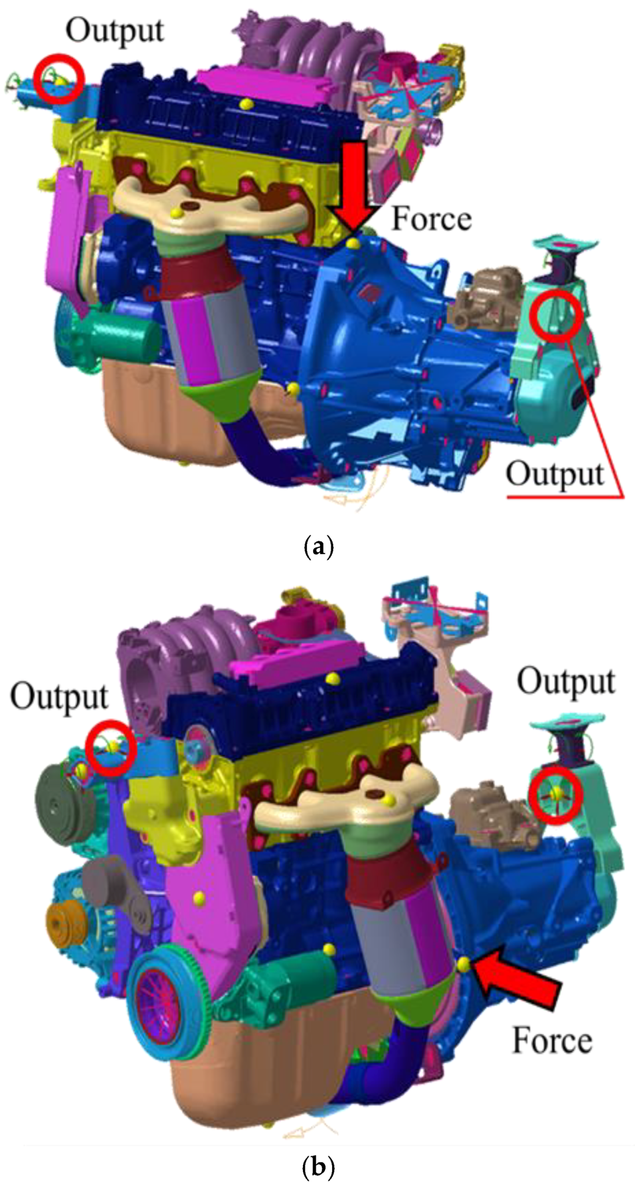
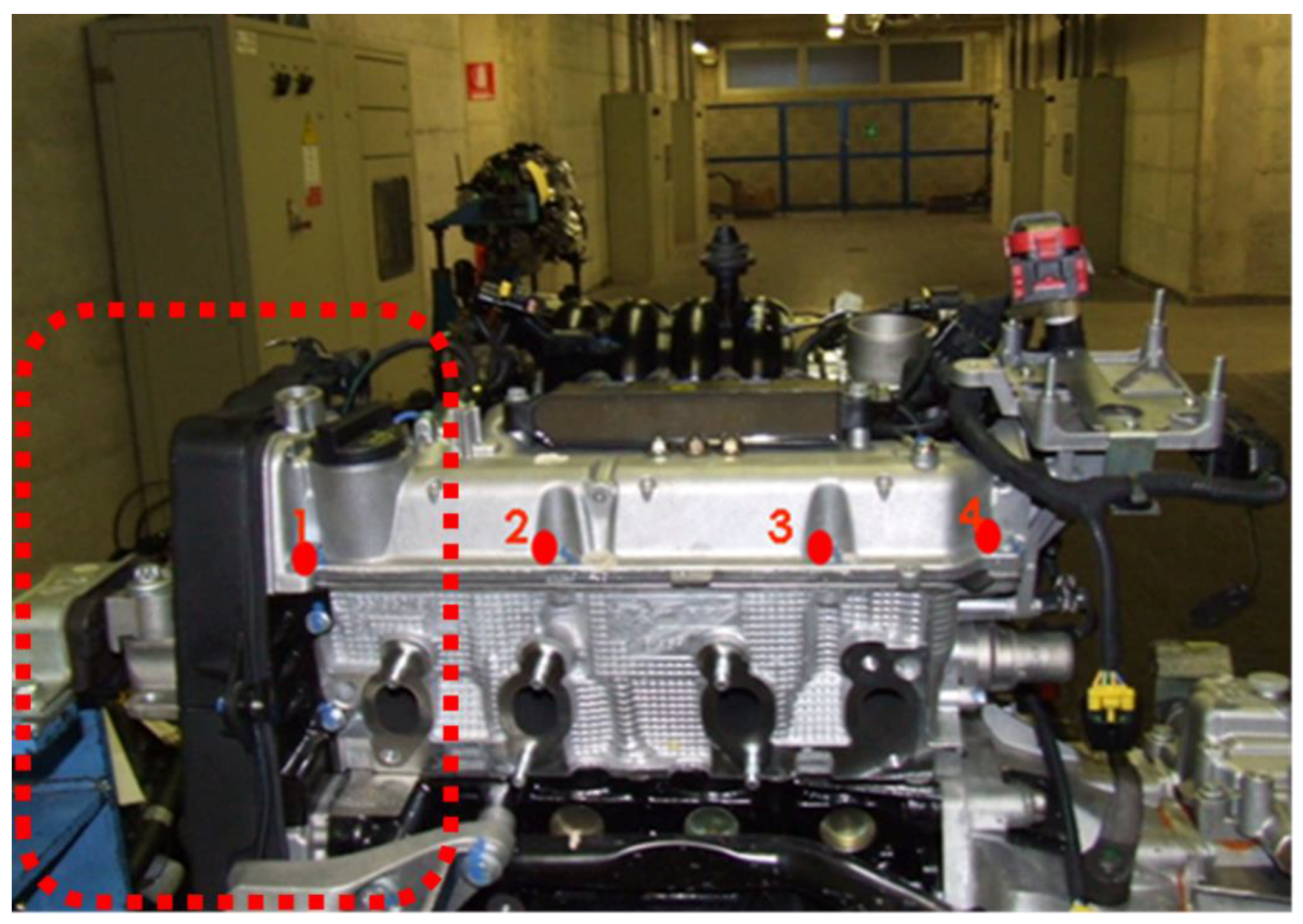
In order to validate the full FEM model, two frequency response function (FRF) analyses were performed: one for the vertical bending and one for the lateral bending. An FRF analysis consists of the application of a unitary force in a given node, followed by measurements of the related accelerations in different nodes of the model. Such relevant points selected for the FRF analyses of the engine are shown in Figure 2 for both the vertical and the lateral bending load case. These numerical analyses replicated the experimental tests previously performed and the results are compared in the following section.
The FEM model was imported in the MSC Nastran to calculate the modal basis of the engine up to a frequency of 1500 Hz (the Lanczos algorithm was used for such a purpose). A damping coefficient equal to 0.03 was considered for all the structural elements. Subsequently, the modal basis was imported in the Siemens LMS Virtual Lab environment, with input and output points defined for either the vertical (Figure 2a) or lateral (Figure 2b) bending. Finally, FRF and modal-based frequency response analyses were performed to calculate the accelerations at the relevant points.
A free-free condition was simulated in all the presented cases. As a matter of fact, the engine mounts are capable of decoupling the dynamic engine behavior from the supporting structure in the whole frequency range considered.
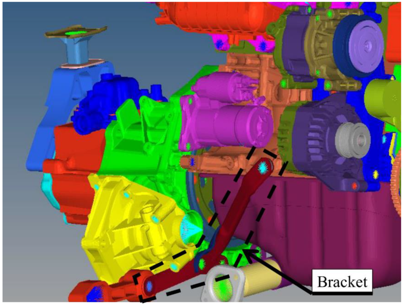
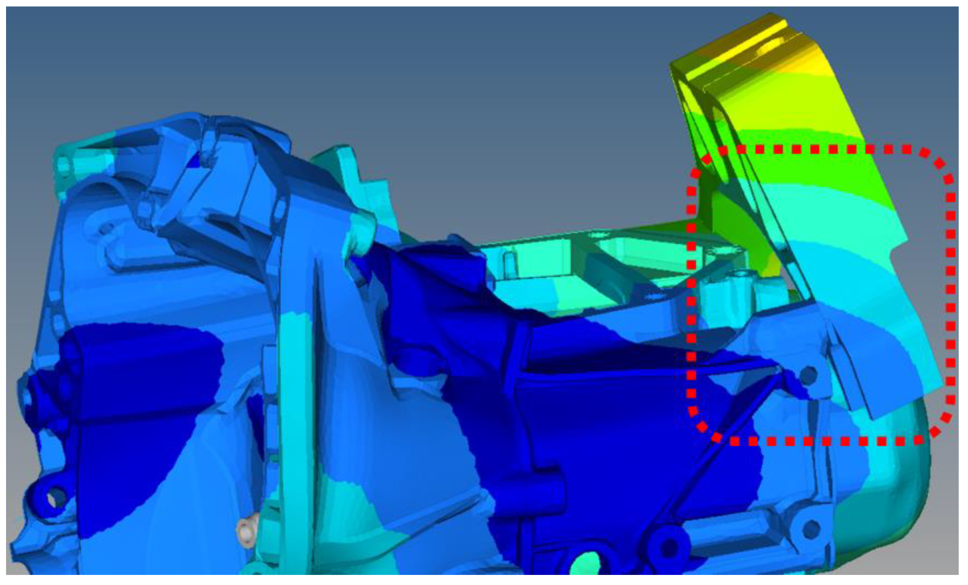
Moreover, the impact of the crankcase–gearbox bracket shown in Figure 3 on the acceleration levels at the previously mentioned relevant points was assessed. Such evaluation was needed to understand whether the impact on the dynamic behavior of the engine was necessary, since its removal would have a positive impact on cost reduction.
3. FRF Results of the Full FEM Model
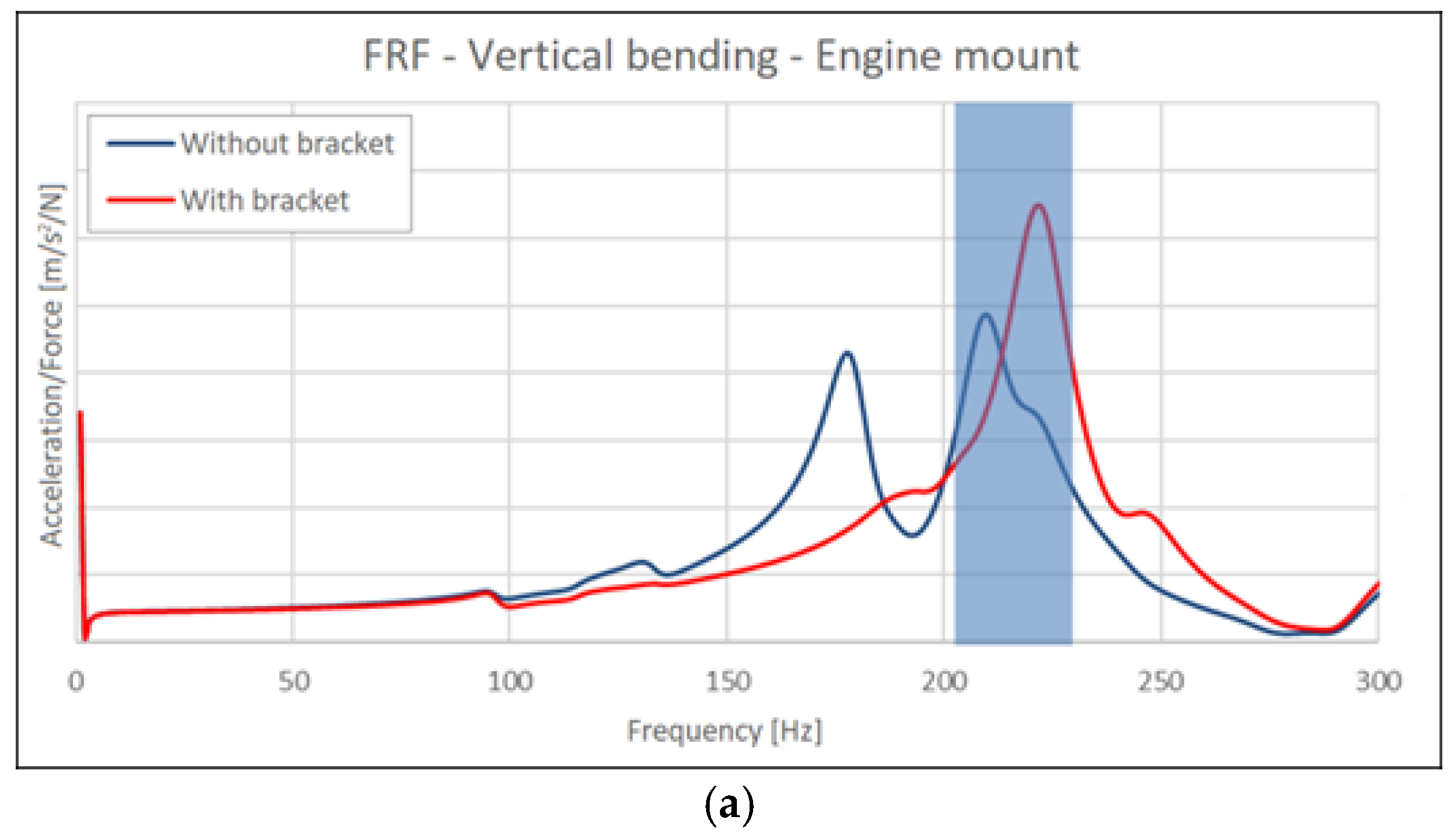
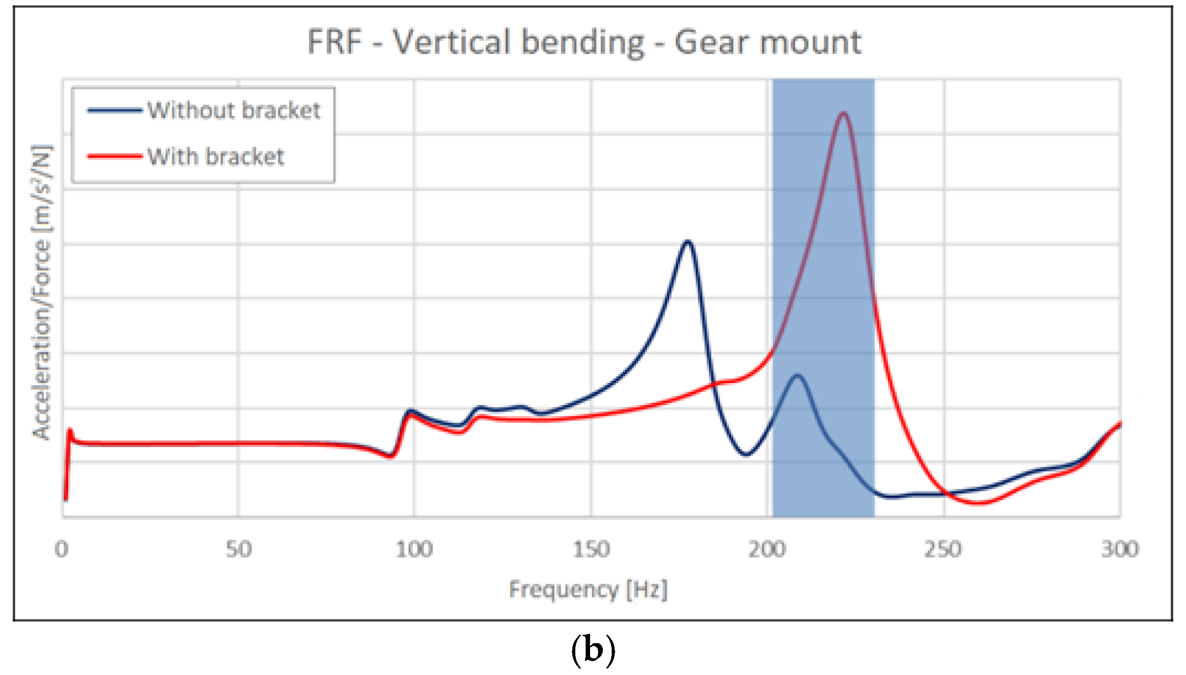
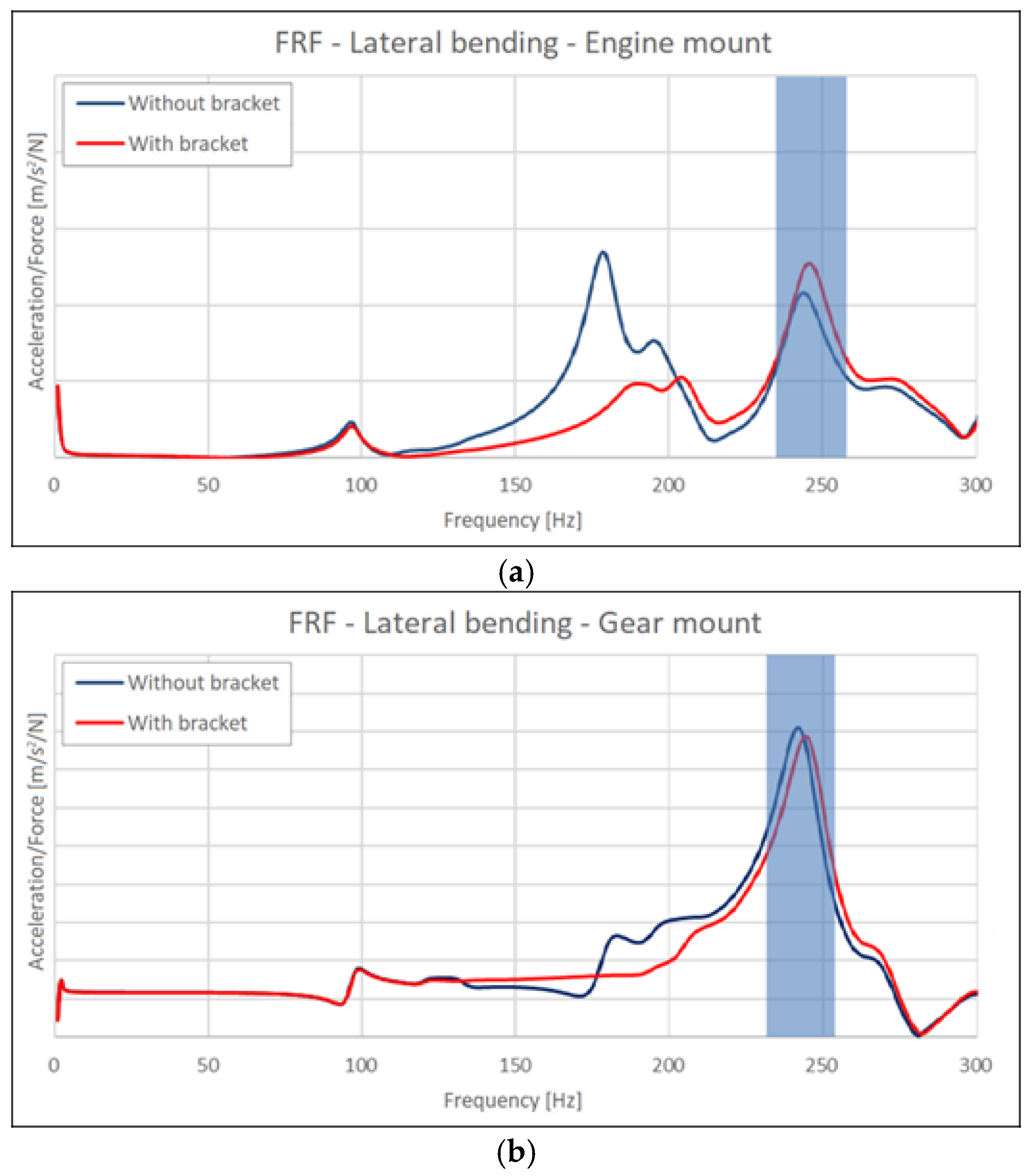
The accelerations were calculated at the engine and gear mounts for the two analyses of vertical and lateral bending (Figure 2). The ratio between acceleration and input force is shown in Figure 4 and Figure 5. In particular, Figure 4 shows results for the vertical bending at both mounts, with and without the engine bracket shown in Figure 3. It is worth noting that the impact of the engine bracket was much more relevant for the vertical bending load case (Figure 4), whereas it played a minor role for the lateral bending load case (Figure 5). This result was expected due to the geometry of the bracket, which allows it to stiffen the engine–gearbox connection, especially when undergoing vertical loads.
From Figure 4, it is possible to see that the bracket introduction is effective in increasing the first natural frequency, in such a way as to avoid any activation of such mode in the whole engine operating range, up to 6000 rpm. As a matter of fact, the second order engine’s highest frequency is equal to 200 Hz, well below the first natural mode whose frequency is now nearly 220 Hz.
From Figure 5, it is possible to see that even if the increase in the first natural frequency is not sufficient to overcome 200 Hz, the corresponding peak is severely smoothed in such a way that it no longer represents a problem, whereas the second more relevant peak is relegated to a frequency much higher than 200 Hz.
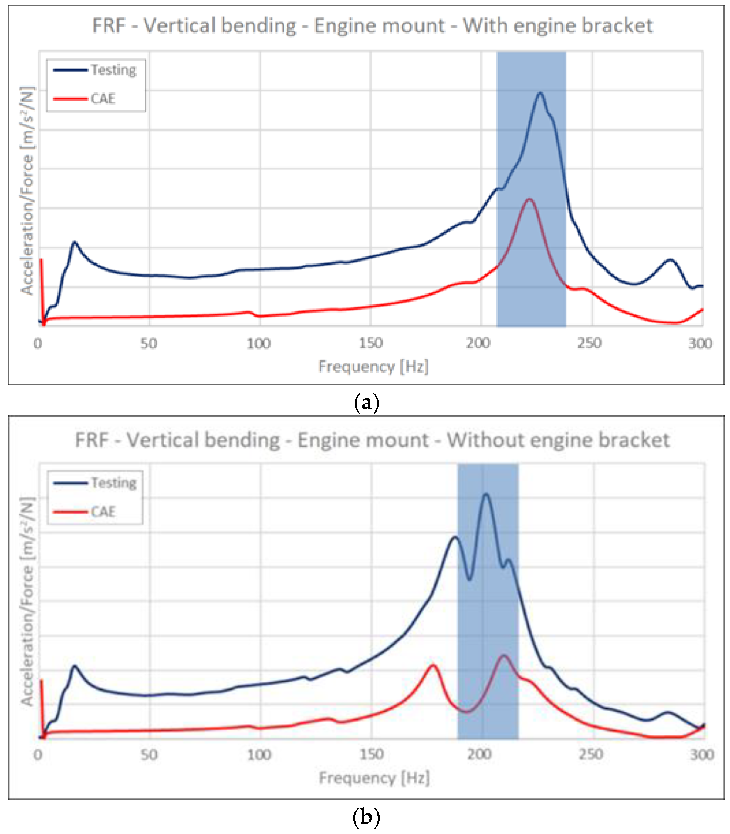
A comparison between the numerical and experimental results is also provided in Figure 6. The FRF results show a satisfactory correlation between experimental outcomes in terms of peak frequencies. The discrepancy in terms of magnitudes was judged as physiological for this kind of analyses because of uncertainties on the correct damping value to be used for the simulation, and because, when modal reduction techniques are adopted it is difficult to make the experimental and numerical exciting/accelerometer points coincident. Figure 6a shows a discrepancy between the peak frequencies of nearly 5 Hz for the model with the engine bracket, whereas Figure 6b shows a discrepancy of nearly 10 Hz between the peak frequencies for the model without the engine bracket. In both cases, such approximations are judged acceptable.
4. Frequency Response Results of the Full FEM Model
Modal-based frequency response analyses were performed for the full FEM engine model, considering the real loads occurring during the operation of the engine. In particular, the wide open throttle (WOT) condition was simulated, thus the maximum intake of air–fuel mixture, occurring when the throttle is completely opened, was considered as the engine working condition. Moreover, vertical loads representing the pistons and roll loads (from crankshaft rotation) were considered. For the former, only loads corresponding to the second engine order were needed (being the remaining negligible), whereas the fourth and sixth order were also added for the latter. Such loads were applied on a RBE3 element that in turn distributed the load onto the elements of interest. The objective of these analyses was to simulate the impact of the aforementioned bracket on the vibrations measured at the mounts during the engine operation. Experimental measurements of the mount vibrations were also available and were used here for validation.
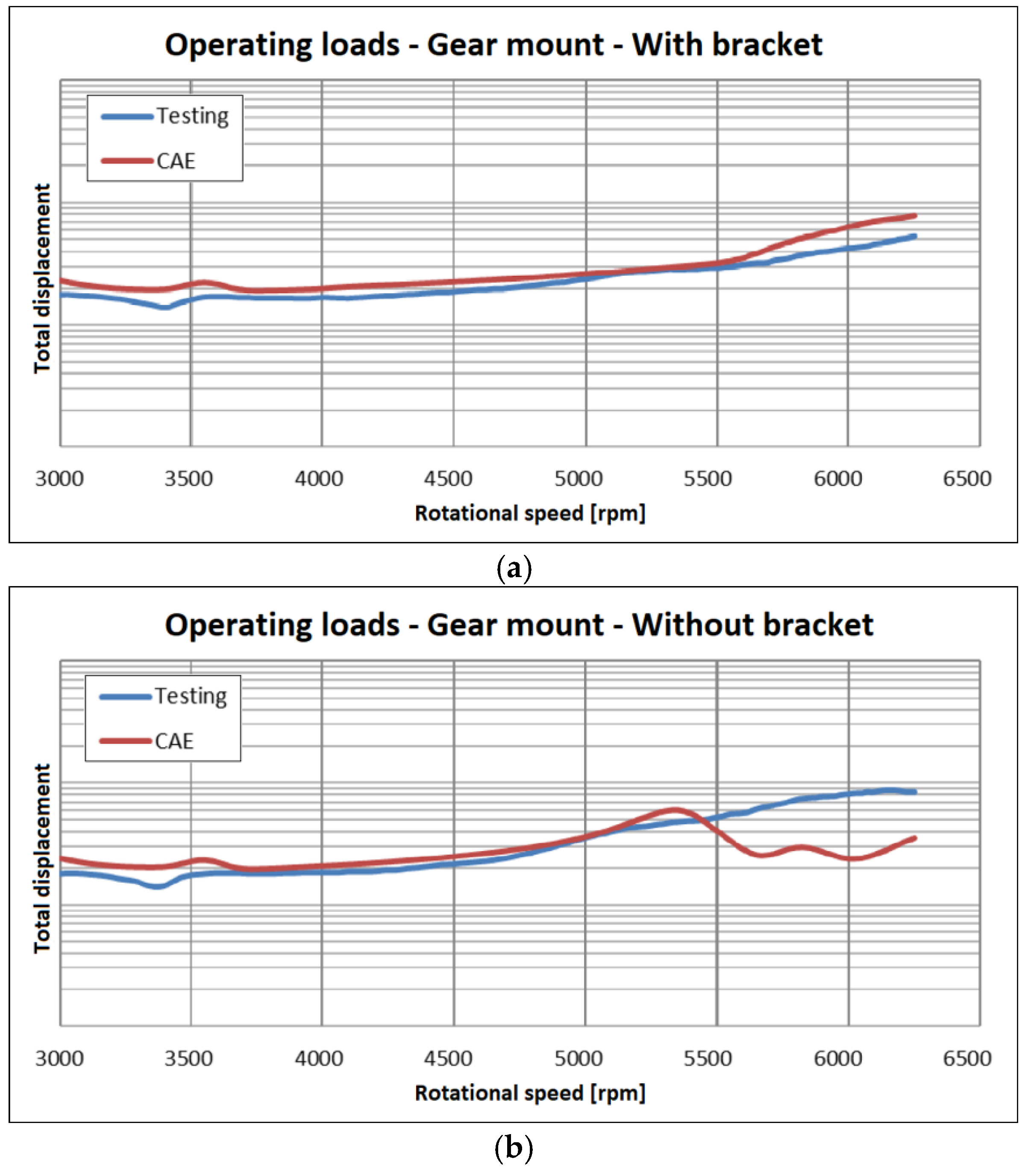
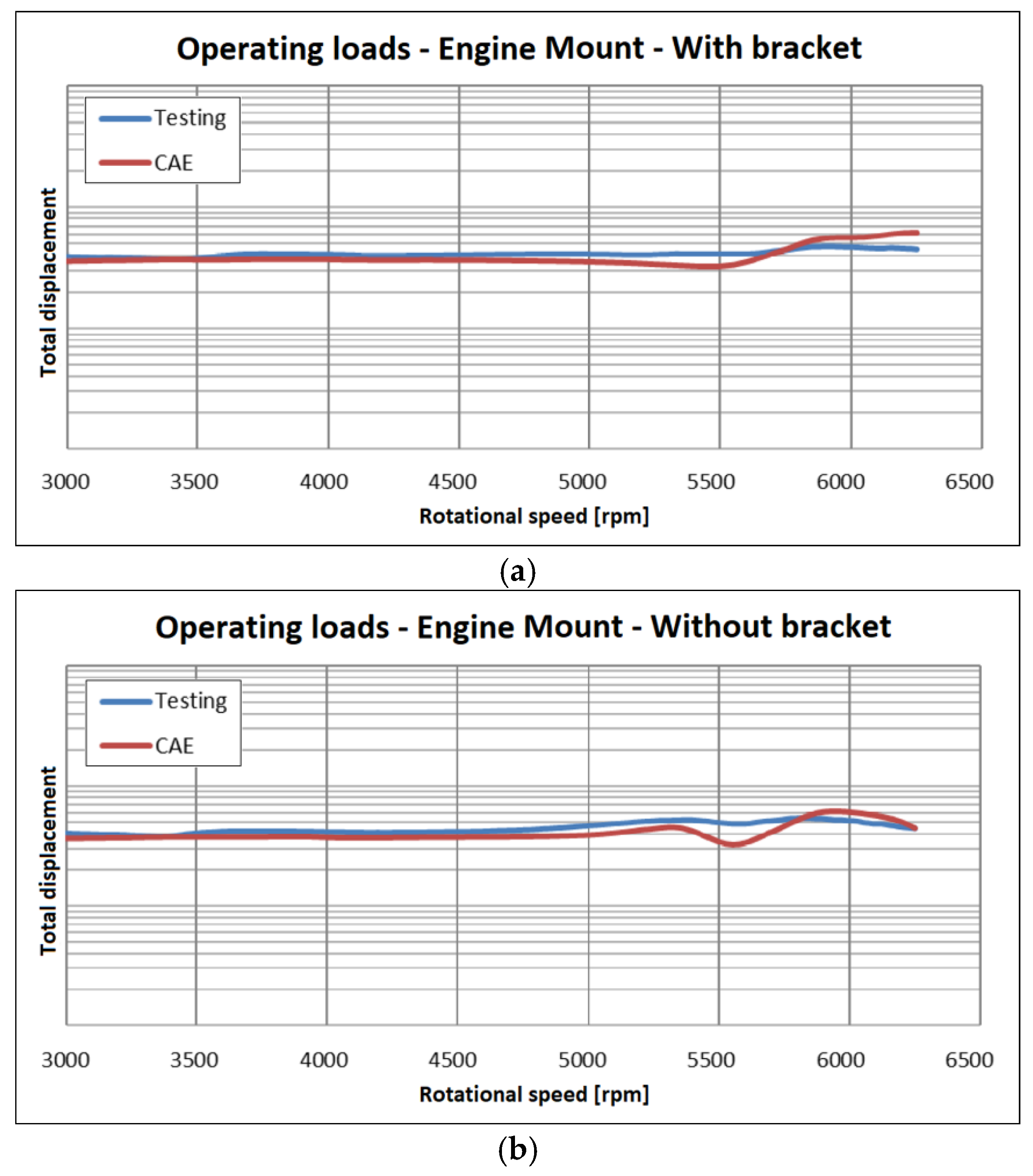
Figure 7 shows the magnitude of the numerical displacement evaluated at the engine and gear mounts, with and without consideration of the presence of the bracket. It is worth noting that the adoption of the bracket has a positive effect at the engine mount just inside the range 5000–5500 rpm, whereas it seems to be ineffective elsewhere. On the contrary, a sensible positive bracket impact on the gear mount total displacement is evident above 4500 rpm. Apparently, only the bracket turns out to increase the magnitude of gear mount vibrations in the 5500–6000 rpm range because, as shown in the following, the model prediction in such a range, with reference to the gear mount, is inaccurate. Considering the experimental outcomes, as expected, the impact of the bracket introduction is also positive in the range 5500–6000 rpm: it is therefore sufficient to compare the blue testing lines of Figure 8a,b to understand that the total displacement is always lower when considering the bracket addition.
Figure 8 and Figure 9 show the experimental/numerical comparisons in terms of the displacements at the gear and engine mounts respectively. The setup for the experimental modal analyses is shown in Figure 10, which also highlights the supporting structure adopted to hold the engine.
As previously anticipated, an acceptable correlation was obtained between the data but not for the gear mounts without the bracket (Figure 8b). A possible explanation could be related to the approximations inherent in the modelling of interface connections between the engine parts, where nonlinear contact conditions are skipped in order to reduce the computational burden but with the consequence of possible unrealistic interpenetration between interface surfaces. This aspect can become critical at high frequency (or namely at high engine rpm) as shown in Figure 11, where it is possible to observe that the gear mount presented excessive relative motions with reference to the gearbox at 210 Hz (referring to the second order, this corresponds to engine rpm slightly higher than 6000). Some remaining discrepancies can be ascribed to the uncertain damping attributed to the structural elements and to the simplified modelling of the bolts that interconnect the different parts of the engine. In any case, the full FEM modelling was considered as validated.
5. Model Reduction
The reduced FEM model was created starting from the full FEM engine model previously presented and validated. This was achieved by means of the ANSA MetaPost [17] code together with the pre-processor Altair Hypermesh and MSC Nastran.
The reduction of the model was performed for the whole engine apart from the sub-components. Namely, the reduced model comprised a fully reduced engine model with the addition of the engine’s non-reduced sub-components (still fully modelled by FEM). This modelling strategy was preferred since it allowed efficient accommodation of the OEMs (Original Equipment Manufacturers) requirements, as they generally require the explicit modelling of their specific sub-components when assembled to an engine. From this standpoint, the model reduction of the engine allowed the significant reduction of the size of the FEM model, and also enabled the possibility of sharing the model without disclosing proprietary information about the engine design.
Sub-components were removed from the full FEM model and PLOTEL elements (PLOT ELements) [14] were used to display the engine shape and size. PLOTEL elements are MSC Nastran dummy elements used only for display purposes and without significance from the dynamic standpoint. Such elements were adopted to represent the correct shape in the relevant positions, e.g., load application points or bolt positions, and also to visualize the correct engine shape and size.
The total mass and stiffness of the engine was associated with an RBE3 [14] element positioned in the cylinder head, whereas further RBE3 elements were also introduced to link the sub-components to the engine, in correspondence with the connecting bolts (these elements allowed transmission of displacements at the relevant positions where sub-components are directly connected).
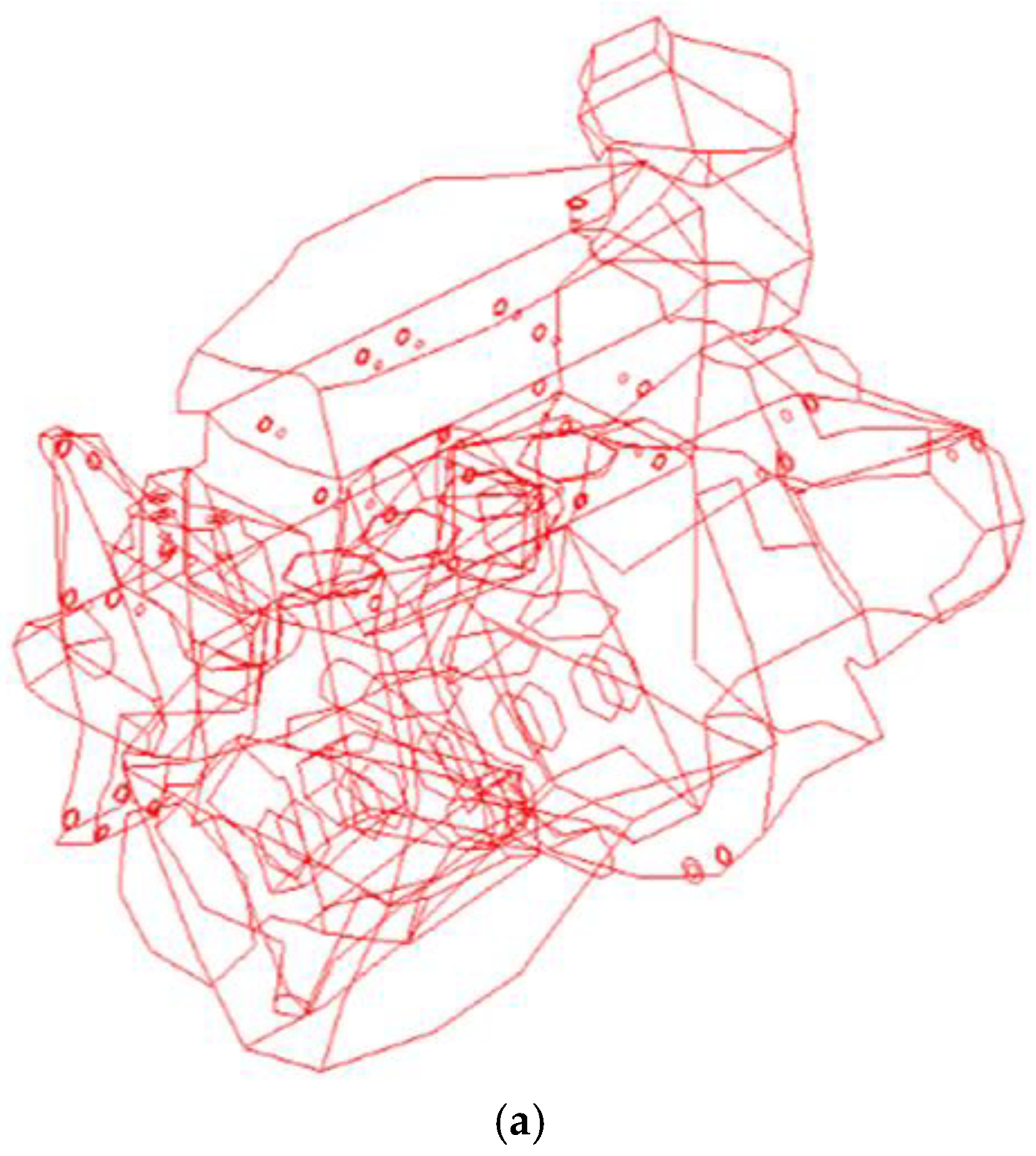
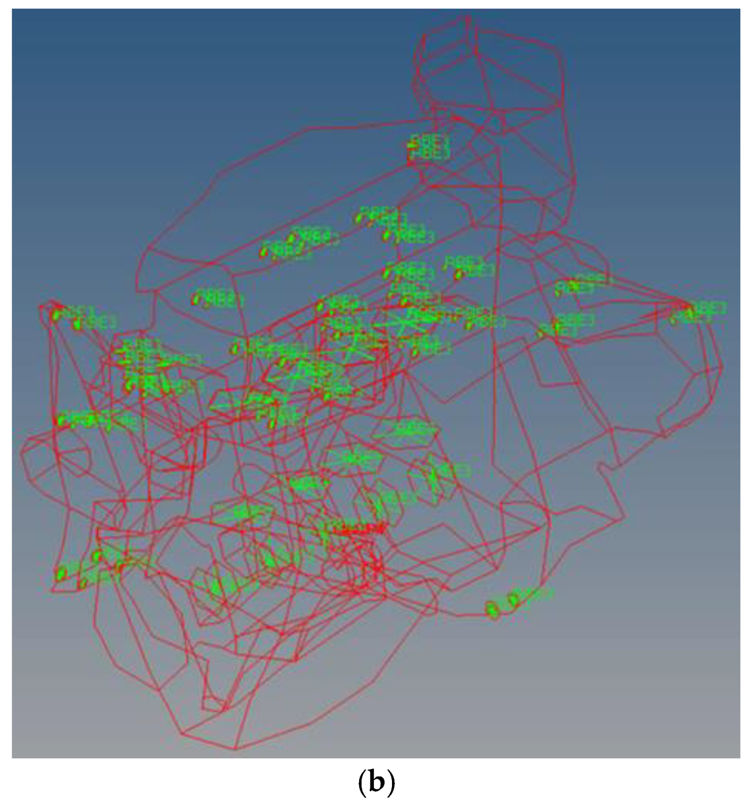
The final reduced model is shown in Figure 12.
The model built up with PLOTEL elements is shown in Figure 12a. It comprised 1885 elements and 1755 nodes (whereas the full FEM model required nearly 5.7 × 10⁶ elements and 4.7 × 10⁶ nodes). Such a model was then imported in the ANSA MetaPost code, in which the modal model was built up by considering the modes of the full FEM model as input data for the reduced model. Consequently, further RBE3 elements were used to link the sub-components at the bolt position, see Figure 12b. The final reduced model comprising all the FEM sub-components is shown in Figure 13.
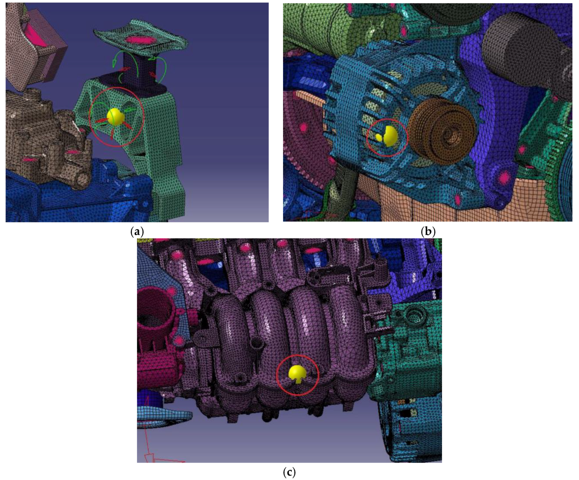
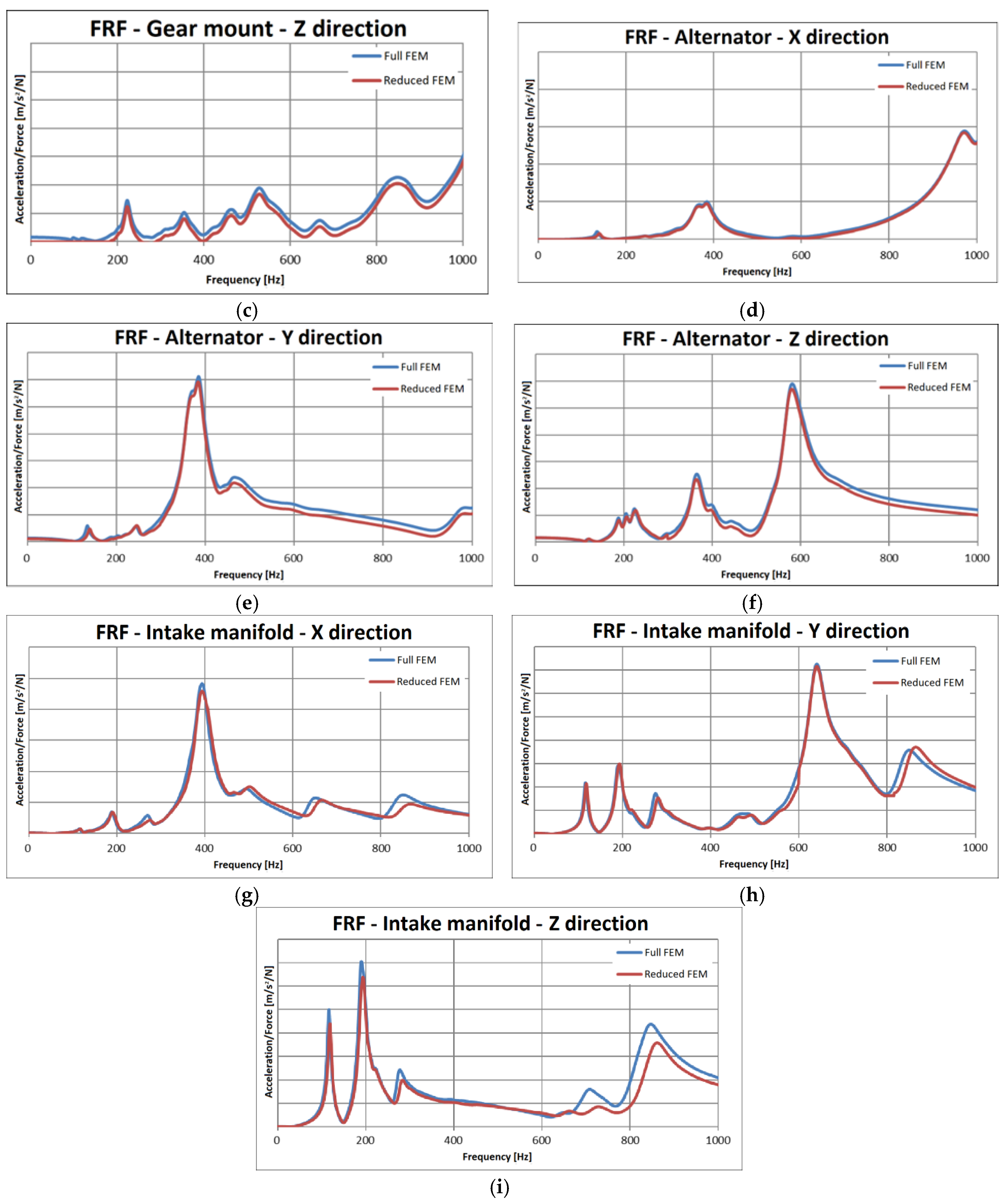
FRF analyses were used to calculate the accelerations at the mounts for the full and reduced FEM model. In this case, unitary forces were applied on the sub-components and the corresponding accelerations were obtained (in the same position of excitation). For instance, Figure 14 shows the points considered in the FRF analyses on the gear mount (Figure 14a), on the alternator (Figure 14b) and on the intake manifold.
6. Results of the Reduced FEM Model
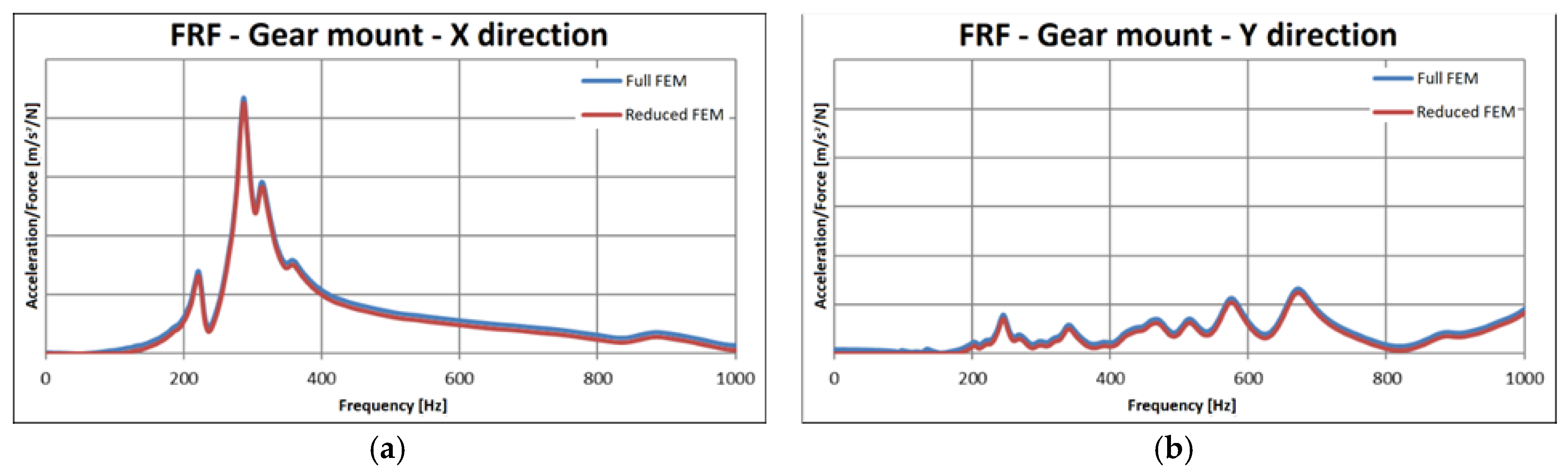
Figure 15 shows the ratios of acceleration over force calculated for the two FRF analyses performed for the alternator and for the gear mount: a quite satisfactory matching was obtained.
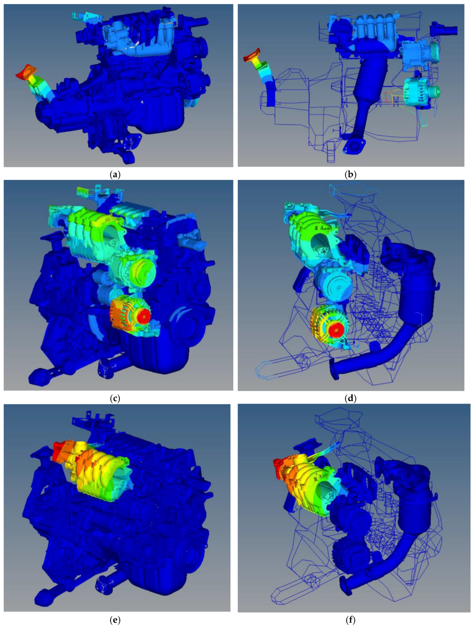
Figure 16 shows three examples of the modal shapes for the full FEM model and the reduced model for three components.
Figure 16 shows an example of the modal shapes for the full FEM model and the reduced model: again, a quite satisfactory matching was obtained.
The reduced FEM modelling allowed the calculation of the accelerations at the sub-components with a reduced computational burden. In particular, the runtime for the full FEM model was equal to nearly 24 h, decreasing to nearly 2 h for the reduced FEM model. The reduced model was then able to accurately replicate the engine’s vibrational behavior and consequently could be adopted for this kind of analysis. Moreover, since the sub-components are generally designed by external partners who require the analysis of the sub-component assembled to the engine, the adoption of the model reduction can overcome the key concern of not sharing proprietary design solutions.
7. Conclusions
A 4-cylinder petrol engine was simulated from the dynamic standpoint by leveraging on the finite element method (FEM). In particular, a reduced modelling strategy based on the component mode synthesis (CMS) was adopted to reduce the size of the full FEM model of the engine.
The FEM model of the engine, comprising all its sub-components, was preliminarily characterized from the vibration standpoint; subsequently, the CMS was adopted in order to reduce the FEM model DoFs.
FRF analyses were used to reproduce the vibration response of the engine and the corresponding acceleration levels between the models and bench test data were compared, showing a sound agreement. Moreover, frequency response analyses were also performed to replicate the vibrations of the engine during the operation and a satisfactory comparison was obtained against corresponding bench test data.
The adopted reduced modelling strategy turned out to be effective in lowering the computational burden from 24 h to nearly 2 h, keeping at the same time an accurate replication of the engine vibration behavior.
The reduced FEM model was demonstrated to reproduce with high accuracy the vibration response at the engine mounts, providing a satisfactory agreement with the vibrations measured experimentally and with the outcomes of a full FEM model.
Ways to further improve the modelling of the bolts and of the interface contacts between the engine parts are still under investigation.
Author Contributions
A.P., M.P. and E.A. conceived and performed the simulations; V.G. wrote the paper, R.C. supervised the work.
Funding
This research received no external funding.
Conflicts of Interest
The authors declare no conflicts of interest.
References
- Craig, R., Jr. Coupling of Substructures for Dynamic Analyses: An Overview. In Proceedings of the AIAA Dynamic Specialists Conference, Atlanta, GA, USA, 3–6 April 2000. AIAA Paper No. 2000–1573. [Google Scholar]
- Zheng, Z.C. Dynamic analysis of nonlinear systems by modal synthesis techniques. Appl. Math. Mech. 1983, 4, 611–623. [Google Scholar] [CrossRef]
- Armentani, E.; Sepe, R.; Parente, A.; Pirelli, M. Vibro-Acoustic Numerical Analysis for the Chain Cover of a Car Engine. Appl. Sci. 2017, 7, 610. [Google Scholar] [CrossRef]
- Armentani, E.; Trapani, R.; Citarella, R.; Parente, A.; Pirelli, M. FEM-BEM Numerical Procedure for Insertion Loss Assessment of an Engine Beauty Cover. Open Mech. Eng. J. 2013, 7, 27. [Google Scholar] [CrossRef]
- Armentani, E.; Caputo, F.; Esposito, L.; Giannella, V.; Citarella, R. Multibody Simulation for the Vibration Analysis of a Turbocharged Diesel Engine. Appl. Sci. 2018, 8, 1192. [Google Scholar] [CrossRef]
- Siano, D.; Citarella, R.; Armentani, E. Simulation of a multi-cylinder engine vibrational behavior. Int. J. Veh. Noise Vib. 2018, 14, 101–123. [Google Scholar] [CrossRef]
- Armentani, E.; Sbarbati, F.; Perrella, M.; Citarella, R. Dynamic analysis of a car engine valve train system. Int. J. Veh. Noise Vib. 2016, 12, 229–240. [Google Scholar] [CrossRef]
- Fehr, J.; Eberhard, P. Simulation process of flexible multibody systems with non-modal model order reduction techniques. Multibody Syst. Dyn. 2011, 25, 313–334. [Google Scholar] [CrossRef]
- Nowakowski, C.; Kurschner, P.; Eberhard, P.; Benner, P. Model reduction of an elastic crankshaft for elastic multibody simulations. J. Appl. Math. Mech. 2013, 93, 198–216. [Google Scholar] [CrossRef]
- Koutsovasilis, P.; Beitelschmidt, M. Comparison of model reduction techniques for large mechanical systems. Multibody Syst. Dyn. 2008, 20, 111–128. [Google Scholar] [CrossRef]
- Witteveen, W. On the modal and non-modal model reduction of metallic structures with variable boundary conditions. World J. Mech. 2012, 2, 311–324. [Google Scholar] [CrossRef]
- Mahdisoozani, H.; Mohsenizadeh, M.; Bahiraei, M.; Kasaeian, A.; Daneshvar, A.; Goodarzi, M.; Reza Safaei, M. Performance Enhancement of Internal Combustion Engines through Vibration Control: State of the Art and Challenges. Appl. Sci. 2019, 9, 406. [Google Scholar] [CrossRef]
- Junhong, Z.; Jun, H. CAE process to simulate and optimise engine noise and vibration. Mech. Syst. Signal Process. 2006, 20, 1400–1409. [Google Scholar] [CrossRef]
- MSC. Nastran User Reference Manual; MSC Software Corporation: Santa Ana, CA, USA, 2006. [Google Scholar]
- SIEMENS-LMS Virtual Lab. User Manual; SIEMENS-LMS Virtual Lab: Plano, TX, USA, 2011. [Google Scholar]
- Altair Engineering. Hypermesh User Manual; Altair Engineering: Troy, MI, USA, 2011. [Google Scholar]
- META Post-Processor, version 16.0; BETA CAE Systems SA: Thessaloniki, Greece, 2015.
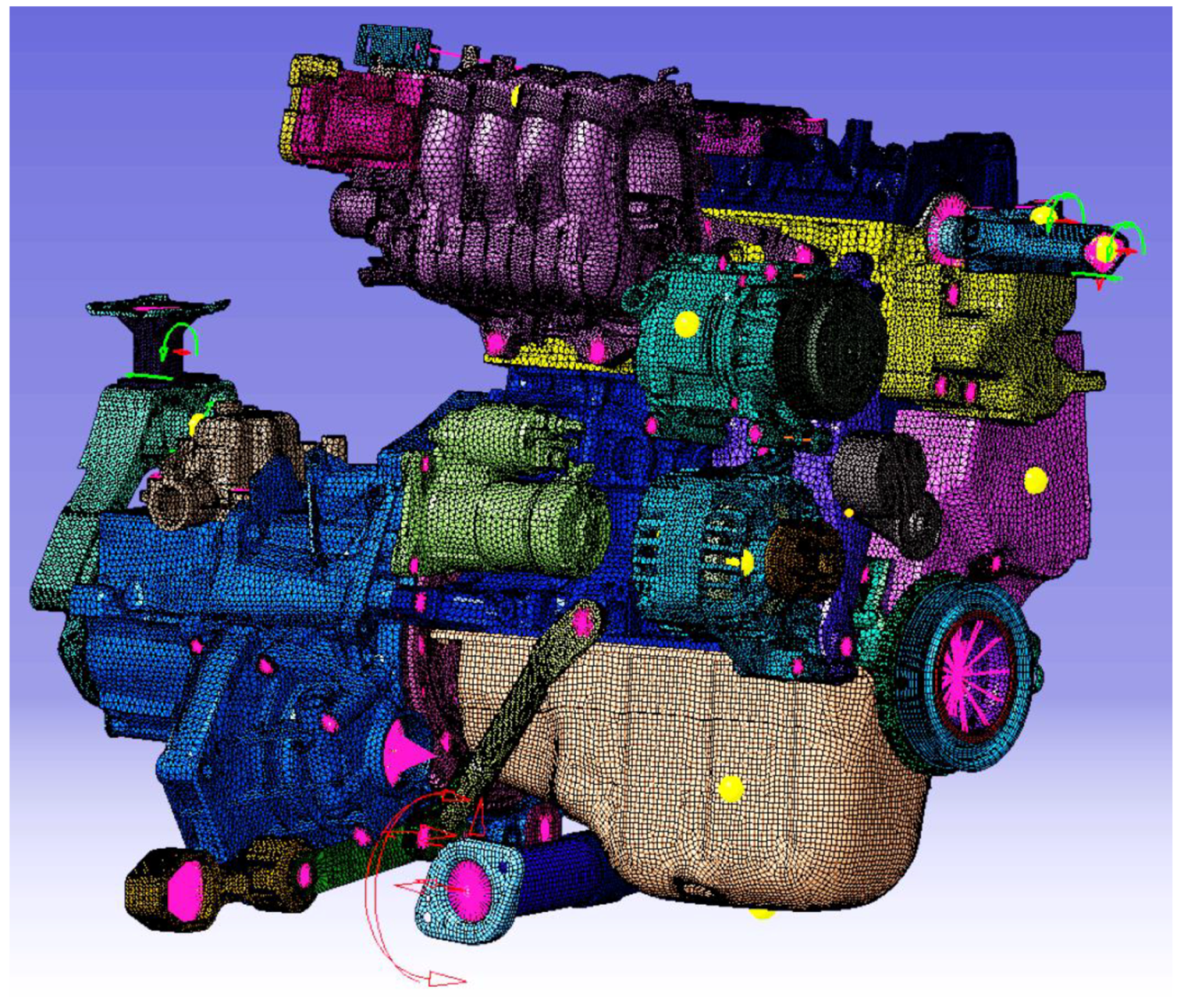
Figure 1.
FEM model of the engine with all its sub-components.

Figure 2.
Full FEM model with details of the relevant points for the FRF analyses for load cases of (a) vertical bending and (b) lateral bending.
Figure 2.
Full FEM model with details of the relevant points for the FRF analyses for load cases of (a) vertical bending and (b) lateral bending.

Figure 3.
Close up of the crankcase–gearbox bracket under analysis.

Figure 4.
Acceleration/force ratio for the full FEM model for the vertical bending load case with and without the crankcase–gearbox bracket (shown in Figure 3) at: (a) engine mount; (b) gear mount.
Figure 4.
Acceleration/force ratio for the full FEM model for the vertical bending load case with and without the crankcase–gearbox bracket (shown in Figure 3) at: (a) engine mount; (b) gear mount.


Figure 5.
Acceleration/force ratio for the full FEM model for the lateral bending load case with and without the crankcase–gearbox bracket (shown in Figure 3) at: (a) engine mount; (b) gear mount.
Figure 5.
Acceleration/force ratio for the full FEM model for the lateral bending load case with and without the crankcase–gearbox bracket (shown in Figure 3) at: (a) engine mount; (b) gear mount.

Figure 6.
Numerical/experimental comparison on the acceleration/force ratio measured at the engine mount for the vertical bending load case: (a) with and (b) without the crankcase–gearbox bracket shown in Figure 3.
Figure 6.
Numerical/experimental comparison on the acceleration/force ratio measured at the engine mount for the vertical bending load case: (a) with and (b) without the crankcase–gearbox bracket shown in Figure 3.

Figure 7.
Displacement magnitude calculated at the (a) engine and (b) gear mounts considering the realistic operating loading condition.
Figure 7.
Displacement magnitude calculated at the (a) engine and (b) gear mounts considering the realistic operating loading condition.

Figure 8.
Experimental/numerical comparison in terms of displacements at the gearbox mount (a) with and (b) without consideration of the bracket highlighted in Figure 3.
Figure 8.
Experimental/numerical comparison in terms of displacements at the gearbox mount (a) with and (b) without consideration of the bracket highlighted in Figure 3.

Figure 9.
Experimental/numerical comparison in terms of displacements at the engine mount (a) with and (b) without consideration of the bracket (highlighted in Figure 3).
Figure 9.
Experimental/numerical comparison in terms of displacements at the engine mount (a) with and (b) without consideration of the bracket (highlighted in Figure 3).

Figure 10.
Experimental setup for modal analyses with highlights of the supporting structure.

Figure 11.
Evidence of the limitations given by the modelling strategy of the contacts, with reference to the relative motion between gear mount and gearbox at 210 Hz.
Figure 11.
Evidence of the limitations given by the modelling strategy of the contacts, with reference to the relative motion between gear mount and gearbox at 210 Hz.

Figure 12.
(a) Engine model built up with PLOTEL elements; (b) highlight of RBE3 elements.


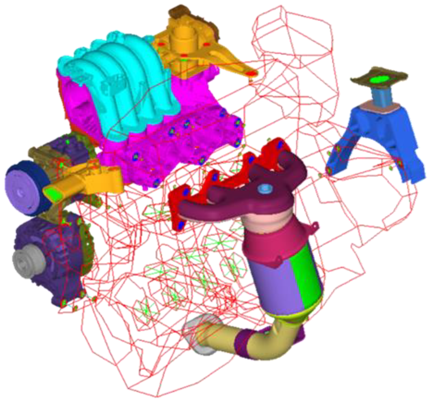
Figure 13.
Reduced model of the engine with all sub-components modelled by FEM.

Figure 14.
Relevant points (yellow dots) on the (a) gear mount; (b) alternator and (c) intake manifold considered in the FRF analyses.
Figure 14.
Relevant points (yellow dots) on the (a) gear mount; (b) alternator and (c) intake manifold considered in the FRF analyses.

Figure 15.
Comparisons of the acceleration/force ratio in the three directions for the full and reduced models at: (a–c) gear mount; (d–f) alternator; (g–i) intake manifold.
Figure 15.
Comparisons of the acceleration/force ratio in the three directions for the full and reduced models at: (a–c) gear mount; (d–f) alternator; (g–i) intake manifold.


Figure 16.
Comparisons of the modal shapes for (a,c,e) the full FEM and (b,d,f) the reduced FEM model for: (a,b) gear mount, (c,d) alternator, (e,f) intake manifold.
Figure 16.
Comparisons of the modal shapes for (a,c,e) the full FEM and (b,d,f) the reduced FEM model for: (a,b) gear mount, (c,d) alternator, (e,f) intake manifold.

© 2019 by the authors. Licensee MDPI, Basel, Switzerland. This article is an open access article distributed under the terms and conditions of the Creative Commons Attribution (CC BY) license (http://creativecommons.org/licenses/by/4.0/).
Share and Cite
MDPI and ACS Style
Armentani, E.; Giannella, V.; Citarella, R.; Parente, A.; Pirelli, M. Substructuring of a Petrol Engine: Dynamic Characterization and Experimental Validation. Appl. Sci. 2019, 9, 4969. https://doi.org/10.3390/app9224969
AMA Style
Armentani E, Giannella V, Citarella R, Parente A, Pirelli M. Substructuring of a Petrol Engine: Dynamic Characterization and Experimental Validation. Applied Sciences. 2019; 9(22):4969. https://doi.org/10.3390/app9224969
Chicago/Turabian StyleArmentani, Enrico, Venanzio Giannella, Roberto Citarella, Antonio Parente, and Mauro Pirelli. 2019. "Substructuring of a Petrol Engine: Dynamic Characterization and Experimental Validation" Applied Sciences 9, no. 22: 4969. https://doi.org/10.3390/app9224969
Note that from the first issue of 2016, this journal uses article numbers instead of page numbers. See further details here.