1. Introduction
Recently, plasma devices generating the streamer type of breakdown in a mixture of noble gases and air have been widely used in medicine (see, for example [
1,
2]). The most typical plasma devices operate at 10–50 kHz frequency with the voltage of 2.5 kV–20 kV, applied to the electrode embedded inside of the dielectric tube. The streamer appears over the positive cycle of the applied voltage and propagates inside and outside of the dielectric tube [
3,
4]. Usually a noble gas is pumping through the dielectric tube since the critical voltage of the breakdown in the noble gases is essentially lower that in the atmospheric air. The streamers propagate over a laminar jet of a noble gas and induces multiple chemical reactions in the mixture of nitrogen, oxygen, water vapor and noble gas some distance apart from the dielectric tube inlet [
5,
6].
The bio-target treated with the plasma jet is exposed to a chemical cocktail of different radicals, ions and the large electric field delivered by the streamer head. The efficiency of treatment depends on numerous parameters, such as the discharge voltage and frequency, plasma device geometry, type of working gas, velocity of flow gas, distance between a discharge tube nozzle and tissue, time of exposing to the plasma etc.
The effect of different types of targets placed in free plasma jets on the plasma characteristics and OH-production was studied previously. In numerical calculations in Ref. [
7], it was shown that an increase of permittivity of targets ranged from plastics to metals enhances the speed of ionization wave and the electron density in the plasma column. In Ref. [
8], the images of plasma interaction with different targets showed an increase of intensity of the optical emission for the grounded electrode beneath. The electric field profile between the nozzle and target over the He plasma jet generated with 30 kHz discharge with 2 kV voltage amplitude was measured in Ref. [
9], using optical emission spectroscopy on a forbidden line of Helium (2
P4
F). The electric field
E delivered by the streamer to the metal grounded electrode is shown to be higher than
E for the glass target case. A considerable rise in OH density values was found in Ref. [
10] with the presence of the metal target compared to the free jet results at the high AC voltage amplitude of 10 or 14 kV. This enlarged value of the OH density was provided with the counter-propagating streamer after impinging the target. In Ref. [
11], an original method to increase the OH generation was developed. Using multiple ring electrodes, more OH-radicals were generated. Compared to the case with only one ring, the device with 12 ring electrodes can generate 3–5 times more OH. It was shown that the multiple electrodes enhance the plasma and OH-radical production only inside the tube rather than in the plasma plume in the surrounding air. A higher discharge current and active species densities were achieved in Ref. [
12] with the installation of an additional floating inner electrode in the plasma device compared to the device only with two outer electrodes. In Ref. [
13], an external biased ring electrode installed between the plasma device and target was used to intensify the streamer characteristics near the target surface. It was shown that the surface electric field and ionization rate were much higher on the dielectric surface than on the conductive one, due to an accumulation of the surface charge, especially with the presence of negatively biased external electrode.
In this work, in the experiment and 2D fluid model simulations, we study the influence of the presence of the grounded substrate beneath the plate with the media and cells on plasma characteristics and the efficiency of cancer cell treatment. Based on the theoretical and experimental results the optimal conditions of CAP jet are formulated and implemented in cancer cell-based experiments. Monitoring the viability of cancer human cell lines A549 and A431 after the CAP jet treatments with various plasma conditions confirms an increase of plasma impact for the optimal plasma parameters.
Following a description of the experimental setups in
Section 2, the results of measurements of plasma jet characteristics and the intensity of OH-line in spectra are given in
Section 3. A brief description of 2D fluid model and a comparison of simulation results of plasma-target interaction with and without the grounded substrate are presented in
Section 4. Materials and methods for study of cells response on CAP treatment are provided in
Section 5 and an influence of CAP jet treatment on the viability of A549, A431 and HEK 293 cells are discussed in
Section 6. Conclusions are given in
Section 7.
2. Experimental Setups
The experimental study of generation of CAP jet is carried out in discharge devices with the coaxial and planar geometries. The plasma sources are shown in
Figure 1. The coaxial device is a dielectric tube with a length of 100 mm and an inner diameter of 8 mm.
A copper powered electrode with a length of 50 mm and with a diameter of 2 mm is inside of the dielectric tube. A capillary insert with a length of 6 mm and an inner diameter of 2.3 mm is placed some distance from the powered electrode. A copper grounded ring with an inner diameter of 18 mm is outside the quartz tube.
In the planar design of the plasma device, two quartz plates (2 mm × 30 mm × 45 mm) are inserted in the cylindrical dielectric frame. The gap between plates is 2 mm. The powered electrode is a copper multi-tip stripe located inside and the grounded electrode is outside. The capillary gap is 1 mm. As seen in
Figure 1b, for the planar plasma device the treated area was elongated up to 45 mm.
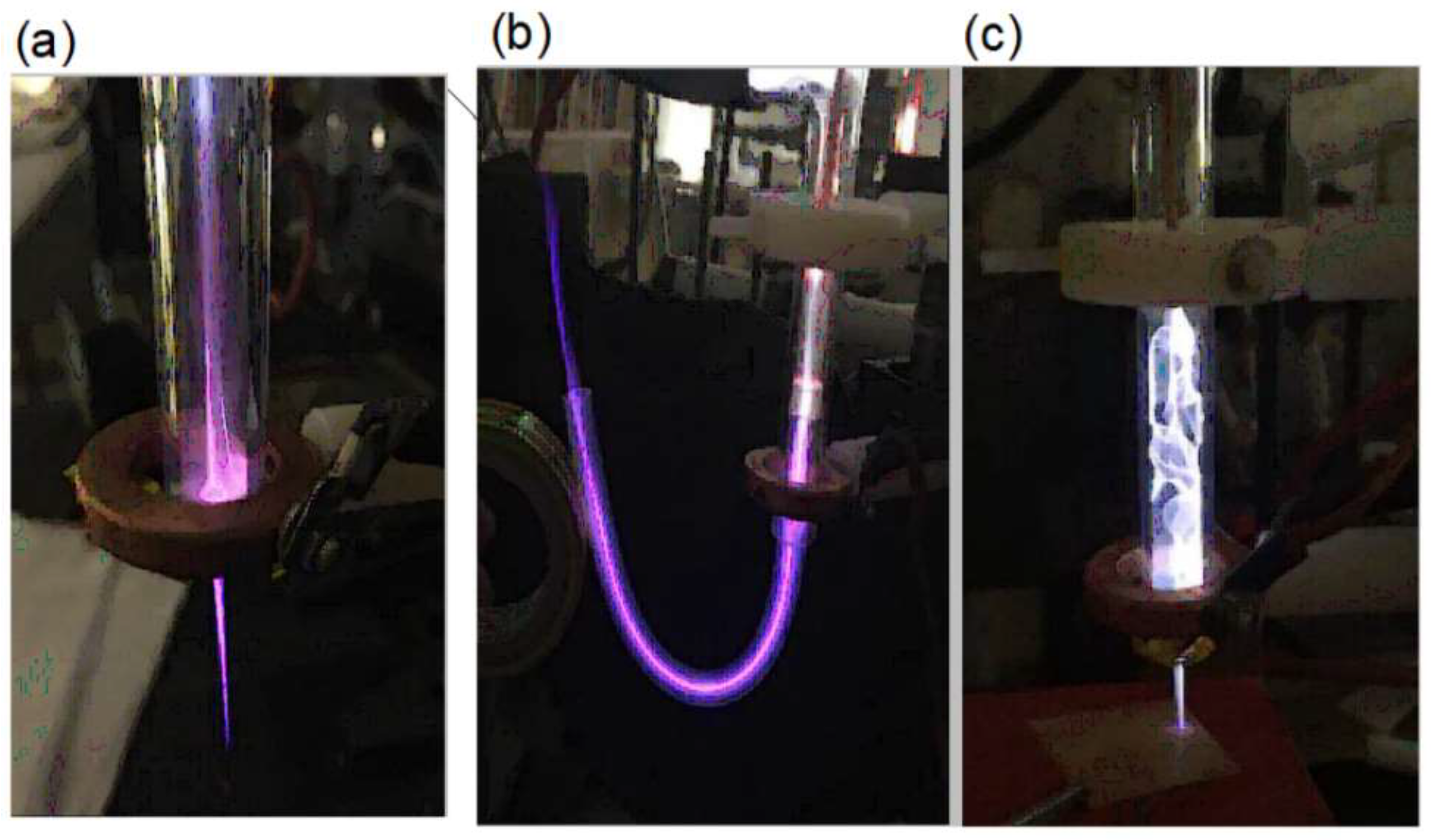
In atmosphere, the helium plasma jet length is of 5–6 cm, but it can be elongated and redirected with a flexible dielectric tube. In
Figure 2a,b, the images of plasma jets without and with a flexible tube inserted in the plasma device are shown. It is seen that the pathway of streamers can be controlled. The argon plasma jet shown in
Figure 2c demonstrates an instability inside of the dielectric tube. The discharge current cords permanently change their trajectories inside the device tube in contrast to the helium quasi-stationary discharge glow (see
Figure 2a).
The gas system supplied working gases with the typical gas flow rate v of 1–10 L/min. A purity of helium and argon are of 99.995% and 99.998%, respectively. The power supply provided a sinusoidal voltage with a frequency of 40 kHz, voltage amplitude U up to 6 kV. In the experiment, the voltage and current of CAP were recorded with a Tektronix TDS 2024 oscilloscope with a passband of 200 MHz. The spectral composition of CAP was registered in the range of 200–750 nm, using a spectrometer with a resolution better than 0.5 nm.
3. Experimental Results on Plasma Jet
With increasing voltage amplitude, the discharge development in helium exhibits four steps. First, at a small voltage, luminous spots on a tip of the powered electrode appear. Then a glow spreads over the gap between the powered electrode and capillary insert. With further increasing U, the glow propagates inside the capillary and finally at some critical voltage the plasma jet starts to propagate beyond the dielectric tube over the inert gas flow in surrounding atmosphere. We found that in argon is essentially higher than in helium for the same gas flow rate v and diameter of capillary insert d. For example, for v = 2 L/min and d = 2.3 mm, is 2.6 kV for helium and = 3.5 kV for argon. Note that does not depend on the flow rate for d > 2.3 mm. The plasma jet length can be up to 60 mm in helium and only 20 mm in argon. An optimal geometry for the argon plasma jet is with the capillary placed at the edge of dielectric nozzle.
The experimental study of plasma jet generation with the planar one slit design source (see
Figure 1b) shows the CAP formation picture which is similar to the coaxial geometry case. The feature of the planar design is that the presence of a multi-tip structure on the plane powered electrode is critical for the plasma jet formation. Please note that the critical voltage of CAP jet generation in helium for the planar source
6 kV, which is much higher than
for the cylindrical design.
The developed plane design of the CAP source allowed us to enlarge the zone exposed to the plasma jet. However, in our experiments with the cancer cell treatment discussed below we used the cylindrical plasma device to provide better uniformity of irradiation of wells with the media and cells without touching the plastic edge of wells.
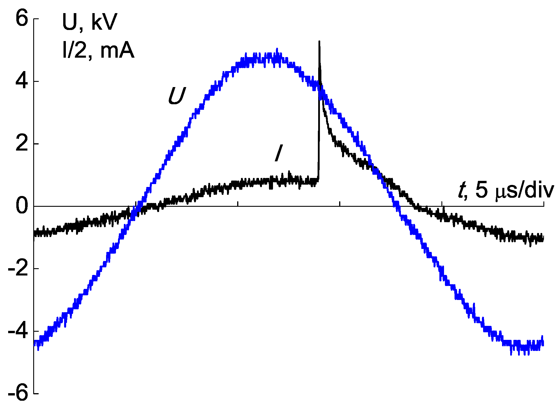
In
Figure 3, the waveforms of the voltage and current are shown for helium working gas. It is seen that the current increases at a positive half-wave of voltage as was observed in Ref. [
4]. For all considered conditions of the CAP generation the discharge current does not exceed 10 mA.
The examples of typical emission spectra of helium and argon CAP are shown in
Figure 4. In addition to helium and argon lines in the plasma jet, there are lines of molecular nitrogen N
, molecular nitrogen ions N
, and nitric oxide NO. In the UV range, weak O
and O
lines are observed, as well as the Balmer series of the hydrogen line.
As seen in
Figure 4, hydroxide OH appears in both spectra of helium and argon CAPs. In our experiments, the OH-radical production with CAP jet over the plasma-target interface was studied for the cases with and without the grounded substrate beneath the plate with the media and cells. As discussed below in
Section 4, the presence of the grounded substrate must amplify the plasma-target interaction.
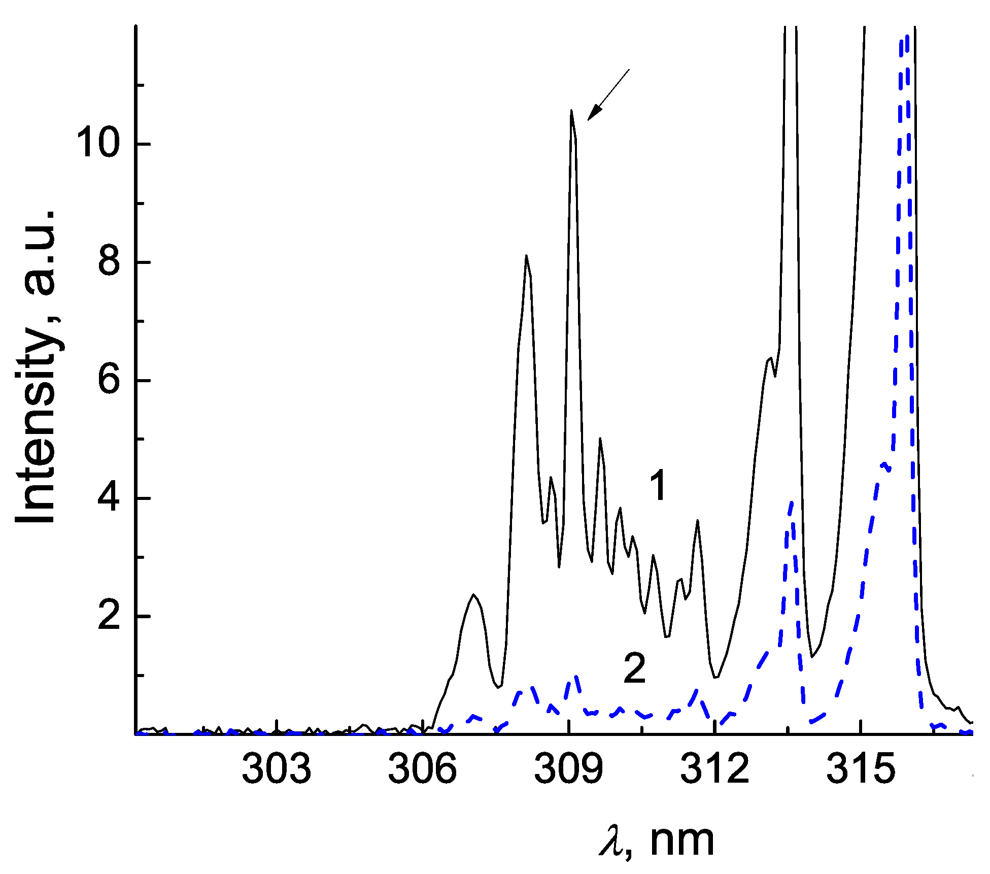
The spectra were measured in gas phase near the interface of plasma and liquid media. A variation of the intensity of OH-peak at
= 309 nm in spectra was recorded for different voltages and gas flow rates. Please note that the peak at
= 309 nm is always dominant in a group of OH-lines over our range of plasma parameters. A part of spectrum with OH-lines and the peak at 309 nm is shown in
Figure 5 for the cases with and without the grounded substrate for
U = 4.8 kV. It is seen that the intensity of OH-lines unexpectedly increases by an order of magnitude after the installation of the grounded substrate. An arrow in
Figure 5 shows the OH-line at
= 309 nm used for our analysis.
In the experiment, the spectra were measured within a range of the voltage from 2.5 kV to 6.5 kV. The intensity of the OH-peak depending on the voltage is given in
Figure 6a. This intensity and consequently, the production rate of OH-radicals start to increase quickly for
4 kV. To illustrate the difference in the OH-production the ratio
R of intensities of OH peaks with and without the grounded substrate is shown in
Figure 6b. For a lower voltage,
3.5 kV, the occurrence of the substrate weakly affects the OH-radical production, whereas for
3.5 kV the ratio
R exhibits a rise of a factor of 10.
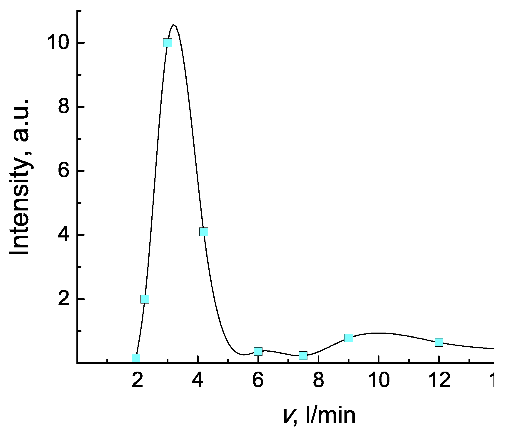
The effect of gas flow rate on the intensity of OH-line at
= 309 nm in spectrum is shown in
Figure 7. The results of measurements indicate a range of flow rate from 2.5 L/min to 4 L/min is optimal for the OH-radical production.
In conclusion to this Section, the plasma devices for plasma jet generation with cylindrical and plane designs were developed and tested. The OH-radicals production rate was studied for different applied voltages and rates of gas flow. A change of the OH-radical intensity peak at = 309 nm was analyzed from the spectra recorded over the point of contact of the plasma jet and target. The comparison of the OH-peak in spectra measured (a) with the grounded substrate beneath the treated target and (b) for the electrically isolated target shows a considerable increase of OH-production for the case (a).
4. Effect of Grounded Electrode Simulation Results
The purpose of this theoretical study is to check the idea to use the grounded metal substrate under the bio-target to enhance the streamer characteristics near the target. The simulations of streamer formation in the plasma device and propagation to the target are performed in the framework of 2D fluid approach with the cylindrical symmetry. The fluid model of the discharge and streamer dynamics includes continuity equations for electrons, ions and mean electron energy and the Poisson equation for the electric potential and electric field. The transport coefficients in the continuity equations for electrons and their mean energy are calculated from the electron energy distribution function, which is calculated with solving the Boltzmann equation for a given
, where
E is the strength of the electric field and
N is the gas density, and a gas mixture. The detail model description is presented in Ref. [
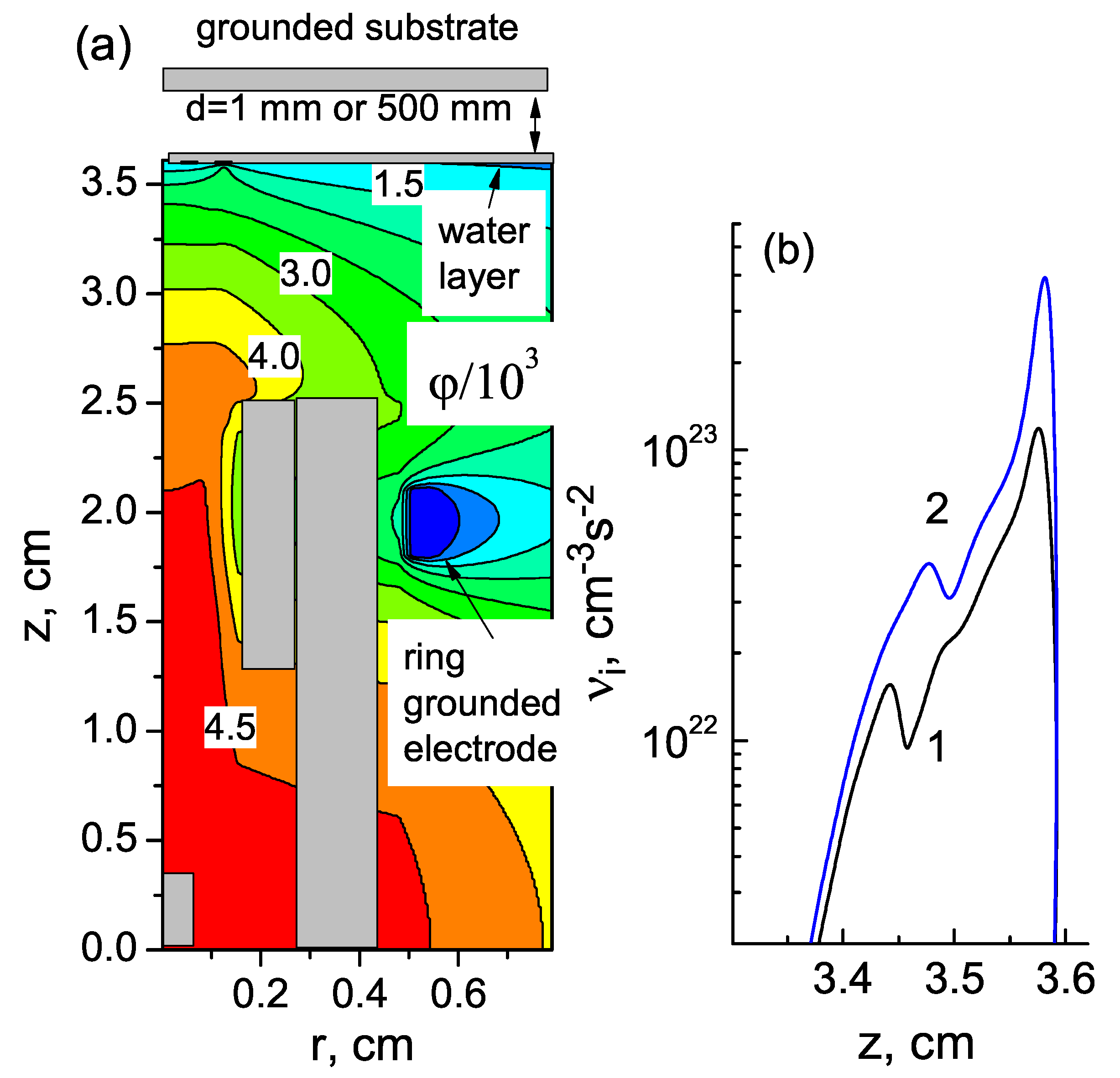
13]. A part of cylindrical simulation domain with the electric potential distribution is shown in
Figure 8a. In simulations, as in the experiment, the streamer propagates to the target and interacts with it. The gas discharge ignition, streamer dynamics and interaction with the target were considered and compared for two positions of the (GR) substrate. In the first case, the GR substrate is placed 1 mm beneath the target and in the second case, the GR substrate is 500 mm from the target. The first and second cases refer to the experimental conditions with and without GR substrate, respectively.
In simulation domain in
Figure 8a, the target is at z = 36 mm. A depth of liquid layer is 5 mm. The radii of nozzle and dielectric tube are 1.15 mm and 2.4 mm, respectively. The length of dielectric tube is 25 mm. The dielectric permittivities of the quartz tube and liquid are 10 and 80, respectively. The radius of calculation domain is 60 mm. The powered electrode is embedded in the dielectric tube as in the experimental plasma device. The external ring grounded electrode with h = 3 mm and r = 4.8 mm is placed at z = 17.5 mm on the dielectric tube. The voltage amplitude
is 4.9 kV and working gas is argon.
In simulations, the gradual voltage increase initiates the streamer formation near the tip of the powered electrode. The streamer propagates first inside of dielectric tube and then over the argon gas flow in the direction to the target. With approaching to the target, the streamer begins to accelerate and the ionization rate increases. The spatial potential distribution for the case without the GR substrate is shown in
Figure 8a for the moment when the streamer touches the target. The potential gradually increases behind the streamer head in the direction of the powered electrode inside the dielectric tube. The position of the grounded ring electrode is seen as a potential dip. The streamer has a toroidal shape, and the point of streamer contact with the water layer is seen in
Figure 8a as the potential bump with coordinates z = 3.58 cm and r = 1.25 mm. At this point the ionization rate has a maximum value. For this moment, the profiles of the ionization rate over z at r = 1.25 mm is shown in
Figure 8b. In simulations, we found that the presence of the grounded substrate beneath the target essentially affects the streamer characteristics. It is seen in
Figure 8b that the ionization rate is four times higher with the GR substrate (curve 1) compared to the case without it (curve 2). The explanation of an increase of the ionization rate can be found from the analysis of the potential distribution.
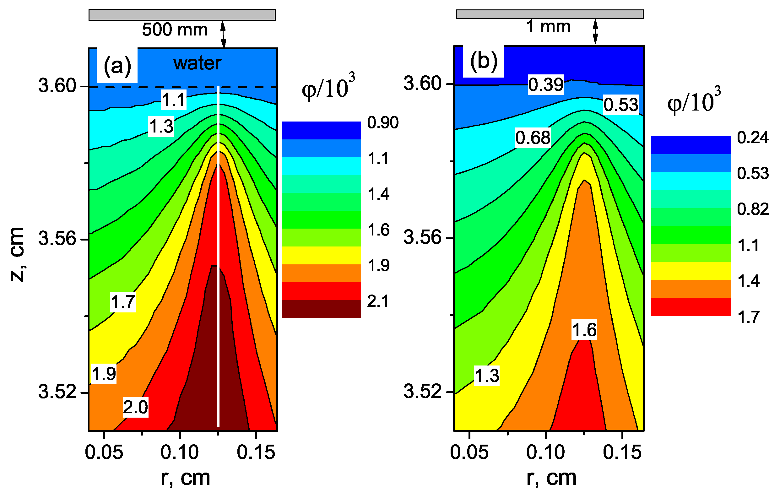
Figure 9 shows a zoom of the electric potential distribution near the liquid layer for two considered cases. The potential on the plasma-liquid interface
kV without the GR substrate beneath and
V with the GR substrate. It is seen that without the GR substrate beneath the target (when the grounded substrate is 500 mm apart from the target) the electric potential on the plasma-liquid interface
is more elevated since the potential drop between the liquid layer and the remote GR substrate is relatively large. The potential drop over the liquid layer is negligible since
= 80. The electric field strength is determined with the potential gradient according the Poisson equation for the electric potential
and electric field
E:
where
,
are electron and ion densities,
e is the elementary charge. Thus, the elevation of
on the plasma-water interface decreases the electric field near the surface and consequently the electron energy and the ionization rate.
The white line in
Figure 9a indicates a trace of the maximum of the ionization rate during streamer propagation from the discharge tube to the target.
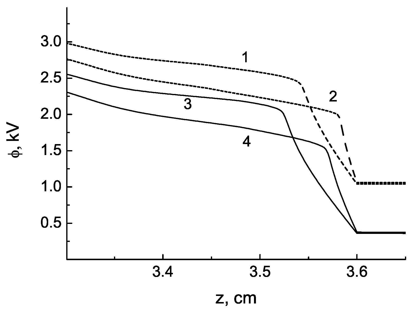
The potential profiles (over white line in
Figure 9a) for different times during the streamer approaching the surface is shown in
Figure 10 for the cases with and without the GR substrate. A higher electrical field near the liquid surface for the case with the GR substrate is provided with a steeper potential drop compared to the case without the GR substrate.
The spatial distributions of the electron density, electron energy, normal component of electric field and ionization rate are shown in
Figure 11 for enhanced plasma jet parameters with the GR substrate.
The maximum of the electron density and energy are 2.5 × 10, cm and 8.3 eV. The and are 56 kV/cm and 26 kV/cm, respectively. If the GR substrate is absent these values are smaller that leads to decrease of the rate of plasma enhanced chemical reactions.
In conclusion of this section, in 2D fluid model simulations, the discharge ignition and streamer dynamics were studied for our experimental conditions. The streamer interaction with the target was calculated for the cases with and without grounded substrate beneath the target. It was shown that the electron density and energy, electric field strength and ionization rate considerably rise with the presence of the grounded substrate without increasing the discharge input power. This recommendation for the plasma jet enhancement was used in the cell-based experiments.
5. Materials and Methods for Study of Cells Response on CAP Treatment
Human cell lines, HEK 293, A431 and A549 were obtained from the American Type Culture Collection (ATCC; Manassas, VA, USA). HEK 293 (kidney embryonic cells) were grown in DMEM medium (Sigma-Aldrich, St. Louis, MO, USA), A431 (skin carcinoma) and A549 (human lung adenocarcinoma cells) were grown in DMEM F12 medium (Sigma-Aldrich, St. Louis, MO, USA) supplemented with 10% fetal bovine serum (FBS; Gibco BRL Co., Gaithersburg, MD, USA), 2 mM L-glutamine, 250 g/mL amphotericin B, and 100 U/mL penicillin/streptomycin—complete medium. When cells were grown for the indirect treatment, all cell lines were cultured in DMEM F12 to unify the experimental conditions.
MTT Assay (Colorimetric assay, 3-(4,5-Dimethylthiazol-2-yl)-2, 5-diphenyltetrazolium bromide) was used to assess cytotoxicity and cell viability.
iCELLigence Assay. Cell proliferation and survival are monitored in real time with the iCELLigence RTCA (Real-Time Cell Analyser) system (ASEA Biosciences lnc., San Diego, CA, USA). The cells were seeded in 8-well E-plates with the integrated microelectronic sensor arrays and cell-to-electrode response is measured. The presence of adherent cells at the electrode-solution interface impedes electron flow. The magnitude of this impedance depends on the number, size and shape of cells. First, the cells were seeded at a density of 30,000 cells per a well in a total volume of 500 L of DMEM F12. For the cytotoxicity assay, after the initial 24 h of cell proliferation, E-plates were pulled from iCELLigence RTCA system and the cells in an 8-well E-plates were treated with CAP jet. Since the diameter of wells on E-plate is larger than the diameter of the plasma jet the E-plates were periodically moving to ensure uniformity of treatment: E-plates were moved 3 times (rectangle-type moving): from the start point of irradiation plate was moved right for 5 mm, next down for 3 mm, next 6 mm left. Period (in seconds) of irradiation in each point was 0.25 of total irradiation. Then, E-plates were returned into the iCELLigence device and cell proliferation was monitored in real time for at least 100 h. Cell index, which reflects cell proliferation in real-time mode was calculated for each E-plate well by RTCA Software 1.2 (Roche Diagnosis, Meylan, France).
6. Viability of A549, A431 and HEK 293 Cells after CAP Jet Treatment
In the indirect treatment of cells with the irradiated medium the various sensitivity of different types of cells was observed. The human cell lines, A431 and HEK293 were seeded in 96-well flat-bottom plates at a density of 5000–10,000 cells in 100
L of DMEM F12 media per well. The same cell-free DMEM F12 media in 12-well plates was exposed to the argon CAP jet during 5 min, 10 min and 15 min at
U = 4.9 kV and v = 4 L/min. The indirect treatment of cells with the irradiated medium was carried out according to the scheme: 1:1, 50% of the initial medium and 50% of the medium treated with plasma. Therefore, 100
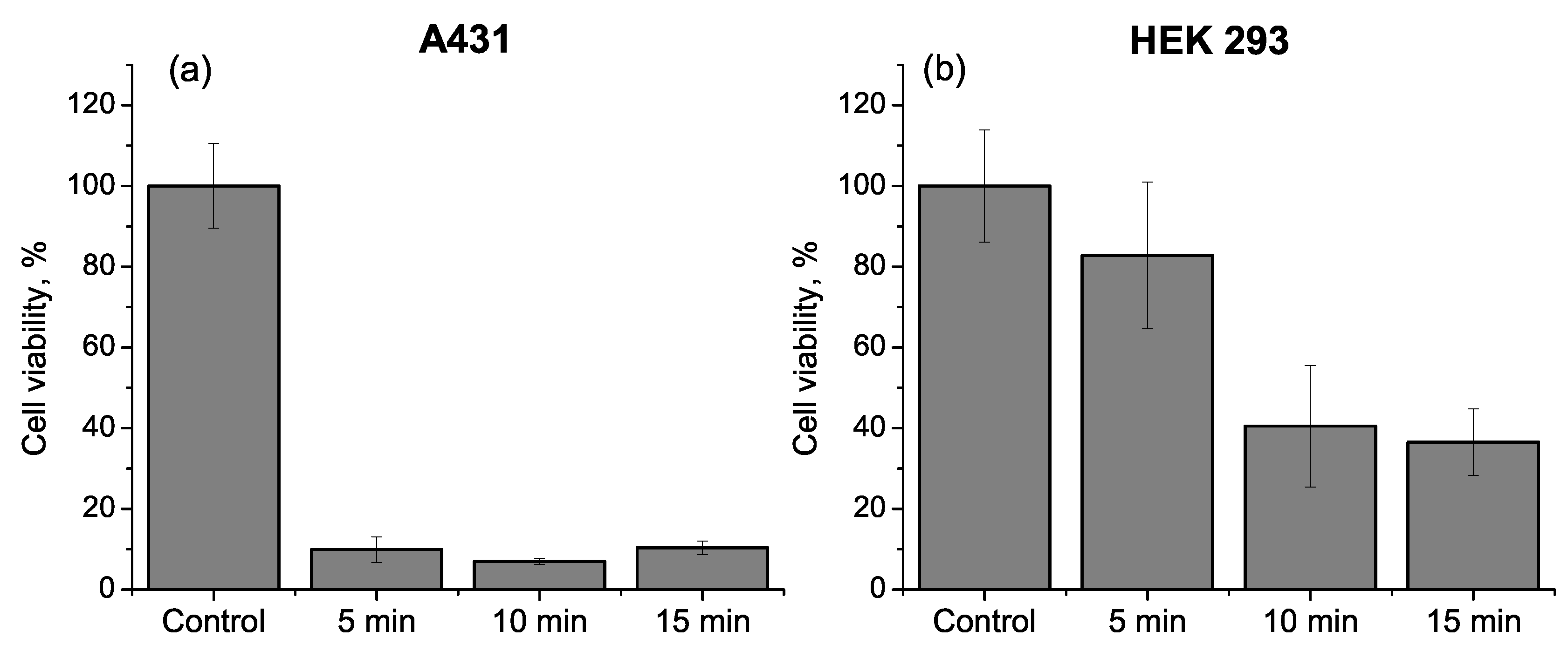
L of treated media was added to each of 96-well flat-bottom plates with cells 15 min after the plasma treatment. To analyze the effect, MMT–Assay of Cell Viability was applied after the treatment. The viability of A431 cells and HEK 293 cells shown in
Figure 12 was quantified 24 h after the media was added. A greater than 90% reduction in A431 cell viability was registered for the case of indirect treatment with the media exposure to the argon CAP jet during 5 min (see
Figure 12a). For the cases of 10 min and 15 min, A431 cells viability is almost the same. In contrast to A431 cells viability, the HEK 293 cells shown in
Figure 12b were less sensitive to the indirect CAP treatment. Indeed, the data showed 80% live cells after the treatment with the media exposed to CAP jet during 5 min. For the cases of 10 min and 15 min, the viability of HEK 293 cells decreases to 40% and 38%, respectively.
The direct treatment with the CAP jet was carried out with A549 cells. In the experiment, A549 human lung adenocarcinoma cells were exposed to argon and helium CAP jets for different voltages, working gas flow rates and with and without the presence of the grounded substrate beneath the plates with the media and cells. MTT assay results in
Figure 13 show the viability of A549 cells 24 and 48 h after the direct argon CAP treatment with and without the grounded substrate. The cells were exposed to the plasma jet during 1 min at
U = 3.6, 4.2 and 4.9 kV.
For a lower voltage plasma treatment, at U = 3.6 kV, 60% cells survive 24 h after the treatment and approximately 35% after 48 h for both cases. So, no visible effect of the grounded substrate was registered. However, at higher voltages, at U = 4.2 kV and 4.9 kV, the use of the grounded substrate significantly enhances the effect of plasma treatment. In this case, the number of survivals drops to almost zero, whereas without the grounded substrate the statistics of cell viability remains the same for all voltages U = 3.6, 4.2 and 4.9 kV. It is seen that for the case of an electrically isolated target an increase of the input power in the plasma device does not enhance an efficiency of the plasma treatment.
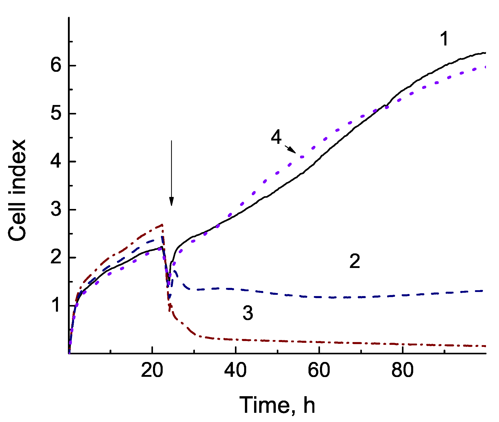
The cell viability was also monitored with iCELLigence instrument to quantify cell proliferation. 30,000 cells were planted per a well of an iCELLigence plate the day before the experiment. A549 cells in an 8-well E-plates were treated for 2 min with argon and helium CAP jets. Taking different parameters of CAP, we wanted to show that the treatment does not work if the plasma parameters are chosen without optimization. First we made experiment with helium plasma jet parameters which are far from the optimal values found in
Section 3,
U = 4.2 kV and v = 5 L/min. For argon plasma jet the parameters of the plasma source
U = 3.6 kV and v = 3 L/min. The cell-based experiments were carried out (a) with the grounded substrate under the plate with cells and (b) without a substrate. In
Figure 14, the real-time generated outputs from the iCELLigence system before and after direct CAP jets treatment are shown. Cell index was calculated for each E-plate well by RTCA Software 1.2 (Roche Diagnosis, Meylan, France). A dip in
Figure 14 refers to the moment when the plate was taken from iCELLigence instrument, irradiated by CAP jet and returned for analysis. Planted cells grow during 24 h before the treatment and 76 h after treatment. iCELLigence data show typical cell index curves that reflect cell proliferation in real-time mode.
For the case without the grounded substrate shown in
Figure 14a, the viability of the cells exposed to helium plasma jet is practically the same as the viability of control cells, whereas for the argon plasma jet the number of survivals essentially diminishes. The low efficiency of helium CAP in this case can be explained by a large helium flow rate, v = 5 L/min. The presence of the grounded substrate enhances the effect of plasma treatment (see
Figure 14b). For this case, the proliferation rate of the cells lowers to 52 % after the treatment with the helium CAP jet and the argon plasma jet treatment kills almost all cells after 24 h.
We found that the argon CAP has a greater impact on the cell viability at lower voltages compared to the helium CAP jet. As seen in
Figure 13 and
Figure 14a, even without grounded substrate, the number of survivals quickly decreases during 48 h. An impact of the argon CAP jet at
U = 3.6 kV looks less aggressive for the case without the grounded substrate, since the cell response begins after several hours after treatment, but not immediately, as with the grounded substrate. It means the
U can be decreased for the former case.
To increase an efficiency of the helium CAP we use the optimal parameters for the OH-radical generation found in
Section 3 and the grounded substrate beneath the plate with cells proposed in
Section 4. According to experimental data shown in
Figure 6b and
Figure 7, the OH-radical generation rate exhibits a maximum at
4.8 kV and v = 3 L/min. The optimal parameters were applied in the experiment with A549 cells. The plasma jet was generated at
U = 5.5 kV, v = 3 L/min and with the grounded substrate beneath the plates. In
Figure 15, the time-dependent viability measured with the iCELLigence system is shown before and after the helium CAP treatment.
It is seen that after the 2 min and 3 min treatments at the same plasma parameters less than 25% and 2.4% of cells, respectively, survived during 100 h of monitoring. In
Figure 15, the data of the indirect CAP treatment is also shown. The media was exposed to the same helium CAP jet during 2 min (with the grounded electrode) and added 15 min after to the wells with cells. The cell index for the case of this indirect treatment practically coincides with the control one. Thus, for indirect treatment the irradiation of media for 2 min, even with the presence of grounded substrate, is insufficient to affect cells.
In conclusion of this Section, the indirect CAP jet treatment of A431 and HEK293 cells with the irradiated medium (>5 min) showed various sensitivity of different types of cells. In the direct treatment, the A549 cancer cells were exposed to argon and helium CAP jets at different voltages and gas flow rates. The plate with the media and cells was placed on a) the dielectric electrically isolated plate or b) the metal grounded substrate. The viability of cells was monitored with MTT assay 24 and 48 hours after the CAP treatment and with iCELLigence Assay 100 h after the treatment. The results of measurements show the high efficiency of CAP treatment during 1–2 min with the presence of the grounded substrate and for optimal values of the voltage and gas flow rate. Note that there is no effect on cell proliferation rate after the indirect treatment with the media with 2 min irradiation in the case of grounded substrate.
7. Conclusions
The typical cold atmospheric plasma jet device with 40 kHz-driven AC voltage of 2.5–6.5 kV amplitude and with the cylindrical and plane designs were developed and tested. The inert gas (helium or argon) was pumping through the plasma device with the rate of 1–5 L/min. The cylindrical plasma device was used for the treatment of cancer cells in vitro.
In this work, for the first time, the grounded substrate was installed beneath the plate with the cells and media for the intensification of the plasma jet treatment. Previously, a strong dependence of the plasma jet characteristics near the surface of targets on their permittivities was reported (see, for example, Refs. [
7,
8]). The metal grounded target was shown can essentially intensify the plasma jet characteristics near the surface. In the experiments and 2D fluid model simulations, the interaction of CAP jet with (a) the bio-target placed on the grounded substrate and (b) electrically isolated bio-target without the metal substrate have been studied and compared. The presence of the grounded substrate was shown to lead to the considerable increase of the electric field over the plasma-media interface. More elevated electron energy and density and OH-radical production rate were registered with the grounded substrate compared to the case without it.
A range of optimal voltage and gas flow rate values for the plasma device for the efficient OH generation was obtained from the measurements of plasma spectra over the plasma-target interface. The intensities of OH-lines at = 309 nm were compared for different plasma jet characteristics and with and without the grounded substrate. When the plate with the media was placed on the grounded substrate, the OH-peak began to increase quickly at U > 4 kV and with further voltage it became 10 times higher than the OH-peak without the substrate. So, the voltage amplitude from 4.5 kV to 5 kV is optimal for the purpose of the OH-production. Please note that for a lower voltage, U < 3.5 kV, the occurrence of the substrate weakly affects the OH-peak in spectra. The measured effect of gas flow rate on the intensity of OH-line at = 309 nm showed that the gas flow rate ranging from 2.5 L/min to 4 L/min is optimal for the OH-radical production.
A drastic effect of the occurrence of the grounded substrate beneath the plate with cancer cells and media have been observed in the measurement of viability of cancer cells after the indirect and direct CAP treatment. The time-dependent viability of human cell lines, A431 (skin carcinoma), HEK 293 (kidney embryonic cells) and A549 (human lung adenocarcinoma cells) was monitored with MTT and iCELLigence assays after the plasma treatment with different CAP jet parameters. It was shown that the direct cancer cell treatment with CAP jets with the optimal plasma parameters and the grounded substrate visibly increased the impact of CAP.

 ,
, 


