1. Introduction
Recently, across the globe, fire accidents in buildings have become bigger, and it has become necessary to build an efficient building disaster management system according to fires in smart cities [
1,
2,
3].
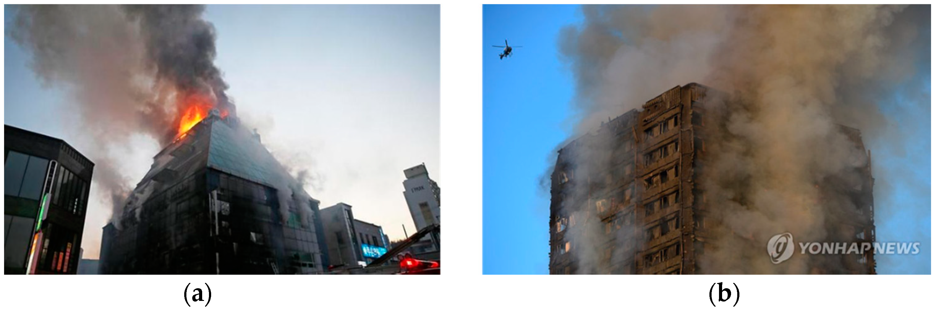
Figure 1 shows recent fire accidents in buildings.
Figure 1a is a fire in Jecheon, Korea, and the
Figure 1b is a fire in London, England [
4]. The common feature of both fires was that quick initial response was difficult due to the absence of a disaster management system. There were no initial response systems, and there was insufficient space for fire engines.
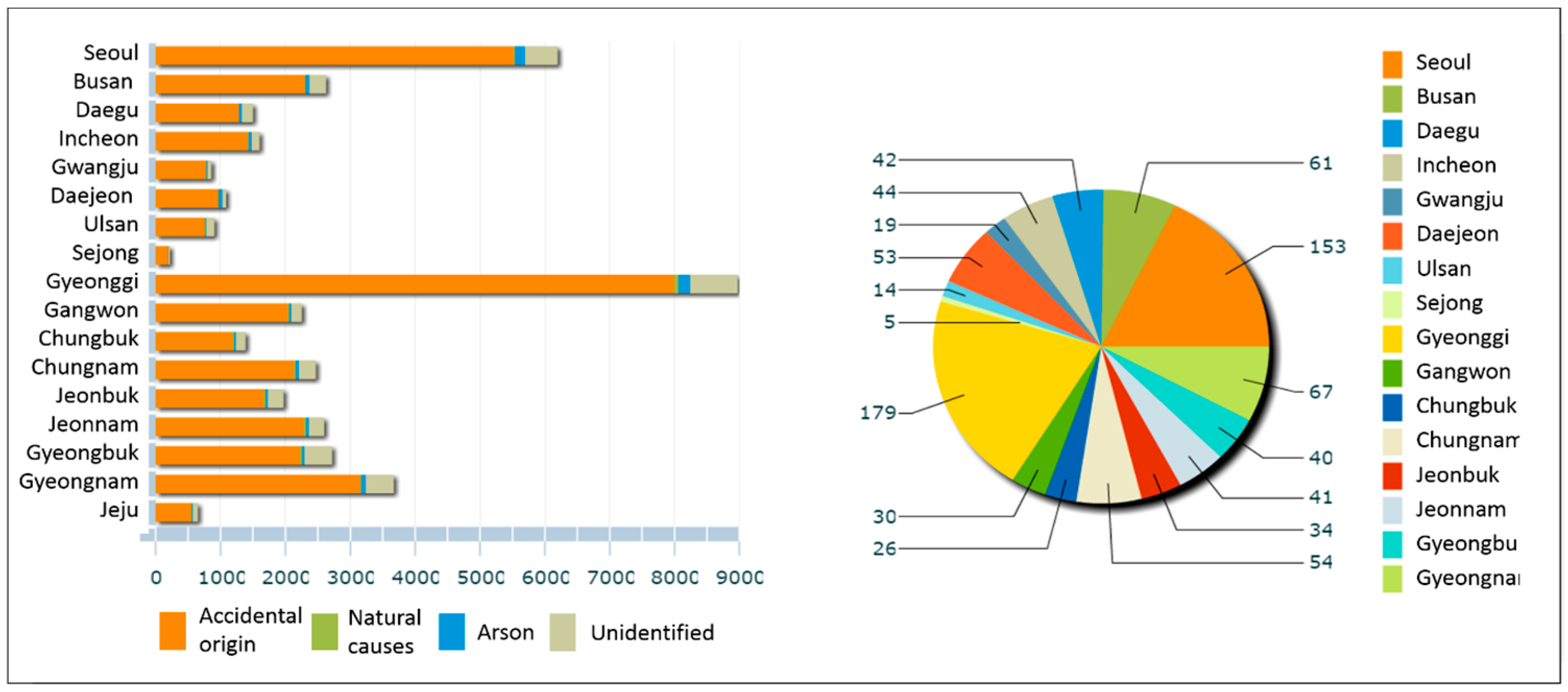
Figure 2 and
Table 1 show the local fire situation in Korea and the cause of human injury and death.
Figure 2 also shows that most fires occurred in metropolitan areas, and many cases of casualties were caused by uncertainty of evacuation route.
Table 1 shows the statistics on personal injury by fire cause in Korea.
Fire in buildings are increasing all over the world. In Korea, the death toll is about 2645, and property damage is worth around 560 trillion dollars (one year) [
5]. Domestic building fires have caused considerable damage in the year, resulting in 2645 people being injured and 533 billion KRW (Korean Won) in property damage. In other words, a smart building disaster management system is necessary to minimize the damage of life and property. In addition, as a result of ignition and cause analysis represented in
Table 1, it can be confirmed that many of the times casualties are caused due to unclear of evacuation routes (falling during the evacuation, unable to escape, and unknown etc.) [
5].
Table 2 classifies the number of fire engines arriving at the site by fire engine arrival time in Korea in 2018. The Seoul Institute in Korea analyzed that of the 20,802 fires, in 14,799 cases fire engines arrived within 5 min. However, when it took five minutes or more for fire engines to arrive, the average property damage amounted to 10,610,000 KRW, 3.6 times larger than the average property damage when fire engines arrived within 5 min [
5].
Therefore, in this paper we propose the following system, with the main goals of this study being:
Intelligent Service: it is necessary to provide information that visualizes augmented reality (AR)-based hazardous area classification and safe evacuation route based on fire area, reflecting characteristics and environment of building areas in smart city infrastructure through linkage of physical and virtual domain in buildings [
6];
Safety Guideline: it is necessary to provide safe guideline service by providing guidance to the occupants and rescuers to reduce the casualties caused by uncertainty of evacuation route in a building that has poor visibility due to fire [
7];
Smart Internet of Things (IoT)-Based Real-Time Remote System: It is expected that IoT-based remote system will be capable of quick response in connection with fire department through providing real-time fire occurrence information [
8].
Analysis of the current status of the various environments and causes of fire in domestic buildings has proven that it is necessary to build a sustainable and cost-effective [
9] AR-based Smart Building Disaster Management System that will be adapted for various environmental factors. In this paper, an AR-based smart building and town disaster management system that provides information visualization and an optimal guide for quick initial response during about 5 min using smart element AR-based disaster management service system is proposed.
This article is organized as follows. The Section Related Works presents the related works, and the Section Smart IoT Based Building and Town Disaster Management System presents the total configuration and architecture of the proposed system. In the Section Control Scenarios, a description of the total four service package flow charts of the proposed system are shown. Section Implementation and Results provides the actual implementation of the proposed system. Finally, the Section Conclusion presents the total results and future aspects.
2. Related Works
Recently, there were several studies on how to make disaster response services faster and more efficient. Among them, there were papers that studied the agent-based simulation service model considering the interaction between crowds and surrounding objects. Also, there have been studies on situation-aware services and automation system for the safety of personnel in the area by linking sensors and IoT devices in the disaster area.
2.1. Intelligent Service for Fire Disaster Response
Neal et al. [
10] proposed a prototype of an agent-based decision support system (ABS) for the simulation of crowd evacuation in the presence of a fire disaster for venues that are specifically intended for mass gatherings such as stadiums and auditoriums. They present a prototype of a computer simulation and decision support system for testing of multiple disaster scenarios at virtually no cost. Jianyong et al. [
11] presented a system simulation model, in which a physical model and a mathematical model are included. Based on the agent technology, they developed a computer program to simulate and analyze the disaster progress in large public buildings through combining rules with numerical calculation. Lu et al. [
12] suggested building an evacuation model that considers the evacuee’s knowledge. The knowledge of the evacuee includes both the spatial knowledge of the stationary environment during a normal situation and the event knowledge of the predictable spatial change for fire-fighting purposes. They presented a simulation system combining human behavior with predictable spatial accessibility in a fire emergency.
However, this agent-based simulation has limits in that it is difficult to provide real-time information to evacuees and rescuers in an actual emergency situation. To improve the limitations of simulation-based disaster response systems that are difficult to deliver real-time information, there were several studies that have built disaster response systems by applying sensors and IoT devices.
2.2. Smart IoT Based Real-Time Remote System
Burak et al. [
13] presented a framework where IoT can enhance public safety by crowd management through sensing services that are provided by smart phones equipped with various types of sensors. They proposed Trustworthy Sensing for Crowd Management (TSCM) for front-end access to the IoT. Bo et al. [
14] presented situation-aware IoT service coordination using the event-driven service-oriented architecture (SOA) paradigm. They focused on the design of an event-driven, service-oriented IoT services coordination platform, and they proposed a reliable real-time data distribution model to support the effective dispatching sensory data between information providers and consumers. Riad et al. [
15] proposed an IoT-based autonomous system for workers’ safety in construction sites with real-time alarming, monitoring, and positioning strategies. They designed an autonomous system that monitors, localizes, and warns site laborers who avail within danger zones. The system architecture is based on Internet of Things. Yusuke et al. [
16] proposed a disaster information cloud system for disaster prevention and reduction. They used IoT devices for gathering data from each site. This system enables to transmit disaster information to residents by the real-time information transmitting to the information communication tools. Khalil et al. [
17] presented a system that is able to transfer all information needed from disaster area to emergency room via a Smart Communication Platform System (SCPS). They presented the main idea of a Disaster Surveillance System (DSS) system that contains part of image processing and recognition methods. They applied this system in water level indicators with IoT sensor devices.
2.3. AR-Based Smart Monitoring Service
Augmented reality (AR) technologies are the next generation computing platform technologies and are destructive technologies that can significantly change the existing ICT market and create new markets. Augmented reality technology is still growing/evolving to the stage of growth, and efforts to create a profit model based on second- and third-generation products continue. The AR technology field is a core technology field that can innovate the ICT market in the future [
18]. In relation to the proposed system, some companies in South Korea have also built a disaster response system. First of all, in order to identify occupants’ location and implement the safety management service using the location information, it is essential to analyze and simulate data using virtual reality (VR)/augmented reality (AR) and IoT based on complex environmental information.
Samsung C&T Corporation is in operation of the “4D Experience on Falling Safety” education where workers experience actual 3D virtual images of workplaces, and recognize the risk factors. Virtual reality machines are used to vicariously experience construction site crashes. In South Korea, firefighting schools implement simulations in the same way as actual emergency situations. Currently, domestic disaster management systems through AR technology is mainly an education method and experience-oriented technology for prevention [
19].
In our system, it is crucial to recognize the position of the occupant and related technologies include beacons, detection sensors (ultrasonic, motion detection, etc.) and detection using radio signal strength. Cornerstones Technology Corp. developed an IoT-based fire evacuation system that guides the escape route optimized for each situation to the evacuee by voice or direction using lighting device in 2016. Korea Telecom (KT) Corp. developed MOS (Monitoring, Maintenance and Management Operation System). This service monitors the temperature, humidity, leaks, fire, etc. of the facilities of buildings, factories, railways, and airports. Based on IoT sensors, this service monitors and controls 24 h at the central control center. Firepro Corp. developed a distributed temperature sensing system that monitors the temperature changes within a cable and monitors the occurrence of the fire early on and minimizes the damage. Hansori Corp. is supplying intelligent fire signs detection system. This intelligent system detects fire signs such as abnormal temperature rising before power outage in various electric power equipment and sends this information to the manager. Smart Technology Corp. developed intelligent video-based fire detection system. This system analyzes video signal inputted from closed-circuit television (CCTV) camera. It is possible to detect fire, smoke, auto detect, and set an alarm. BOSCH Security Corp. developed and commercialized intelligent image analysis technology that can detect objects. This technology can detect intrusion and explosive objects in airports, railroad stations, power plants, and so on. There are several disaster-aware and IoT-based disaster management systems. However, systems that aid rapid rescue and provide simulation and guidance for evacuation are few in number. Additionally, there is no remote system based on IoT that can cooperate with the actual fire department to quicken response. The proposed system in this paper can allow safer rescues by providing guidance to occupants in the case of an actual fire. Augmented reality technology is applied for rapid rescue, evacuation simulation, and guidance. Also, this IoT-based remote system provides real-time fire occurrence information, and can allow for quick cooperation with the fire department.
Table 3 shows differences of the proposed system compared with the existing system.
3. Smart IoT Based Building and Town Disaster Management System (BTDMS)
The following is a chapter that introduces the system architecture, system diagrams, components, and algorithms of the proposed system. This chapter shows the specific components and functions of the system architecture, the actual components for system development, and the fire extinguish and fire escape guidance algorithm.
3.1. System Architecture
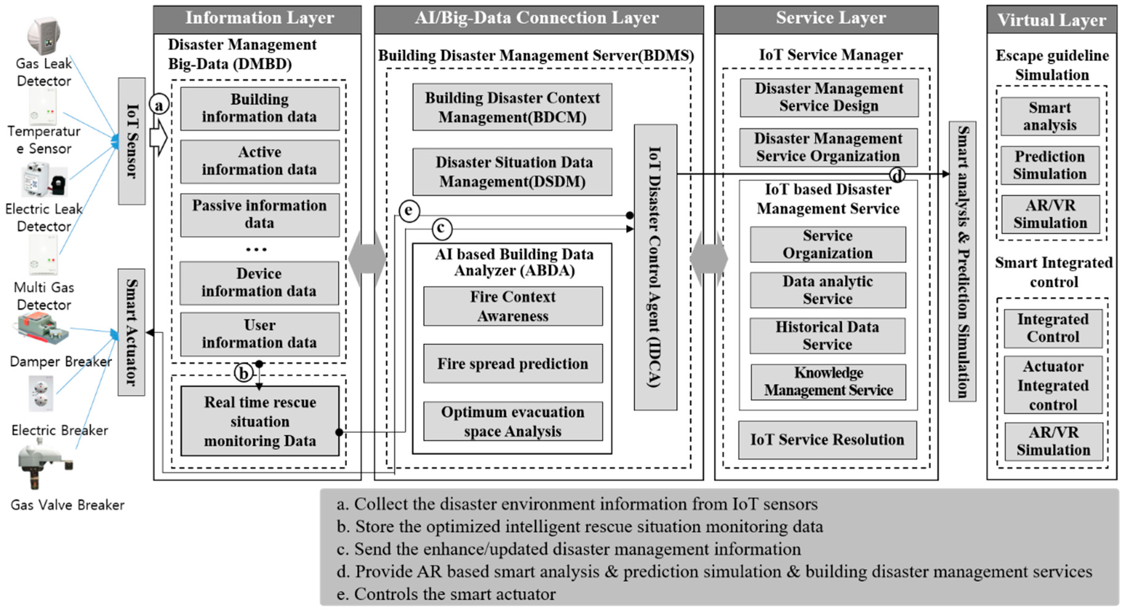
The proposed system consists of the information layer, AI/big-data connection layer, service layer, and virtual layer as shown in
Figure 3. The data obtained by the sensor is stored in the disaster management big-data (DMBD) of the information layer, and the AI/big-data connection layer enables the fire detection and fire occurrence prediction. Also, it provides service to inform the rescuers about the optimal evacuation route based on AR through the service layer and the virtual layer. Then the BDMS controls the actuators appropriately to cope with the fire. The functions of each layer are as follows:
Information Layer: In the information layer, there are many types of data such as building disaster management data, user location data, device and sensor data, user behavior data, and rescue situation monitoring data in the information layer. Disaster environment information collected from the sensors are stored and processed in the DMBD. The IoT sensors gather the disaster environment information and send the data to the DMBD. Rescue situation monitoring data created through the IoT disaster control agent (IDCA) are stored in the real time rescue situation monitoring data module, and the enhanced/updated data is sent to the IDCA;
AI/Big-Data Connection Layer: The AI/big-data connection layer implements the key roles in the disaster management system and classifies building information data, device information data, user information data, and real time rescue situation monitoring analysis data coming from the information layer for the disaster forecast and management service. The building disaster management server (BDMS) in the AI/big-data connection layer is composed of building disaster context management (BDCM), disaster situation data management (DSDM), AI-based building data analyzer (ABDA), and IoT disaster control agent (IDCA). The roles of BDCM are management of fire disaster, environmental context, and user location, data gathering information, and data storage. The DSDM manages the lists of disaster management service and the way of IoT sensors/actuators and provides necessary information. Thus, the AI/big-data connection layer is classified as fire context awareness, fire spread prediction, and optimum evacuation space analysis coming from the information layer through the ABDA and the IDCA;
Service Layer: The service layer is where the optimum disaster management evacuation takes place; it provides services such as the fire context awareness, fire spread prediction, optimum evacuation space analysis, and actuator integrated control, etc. It is responsible for providing optimum service to users and receiving disaster control information from the IDCA. It is composed of disaster management service design (DMSD), disaster management service organization (DMSO), IoT based disaster management service (IDMS), and IoT service resolution (ISR) module;
Virtual Layer: The virtual layer provides a service that confirmation of evacuation place. It selects the best fit evacuation place and provides AR-based optimum escape guidelines. Also, it provides the safety facilities information for AR-based intelligent configuration of the safe/unsafe area.
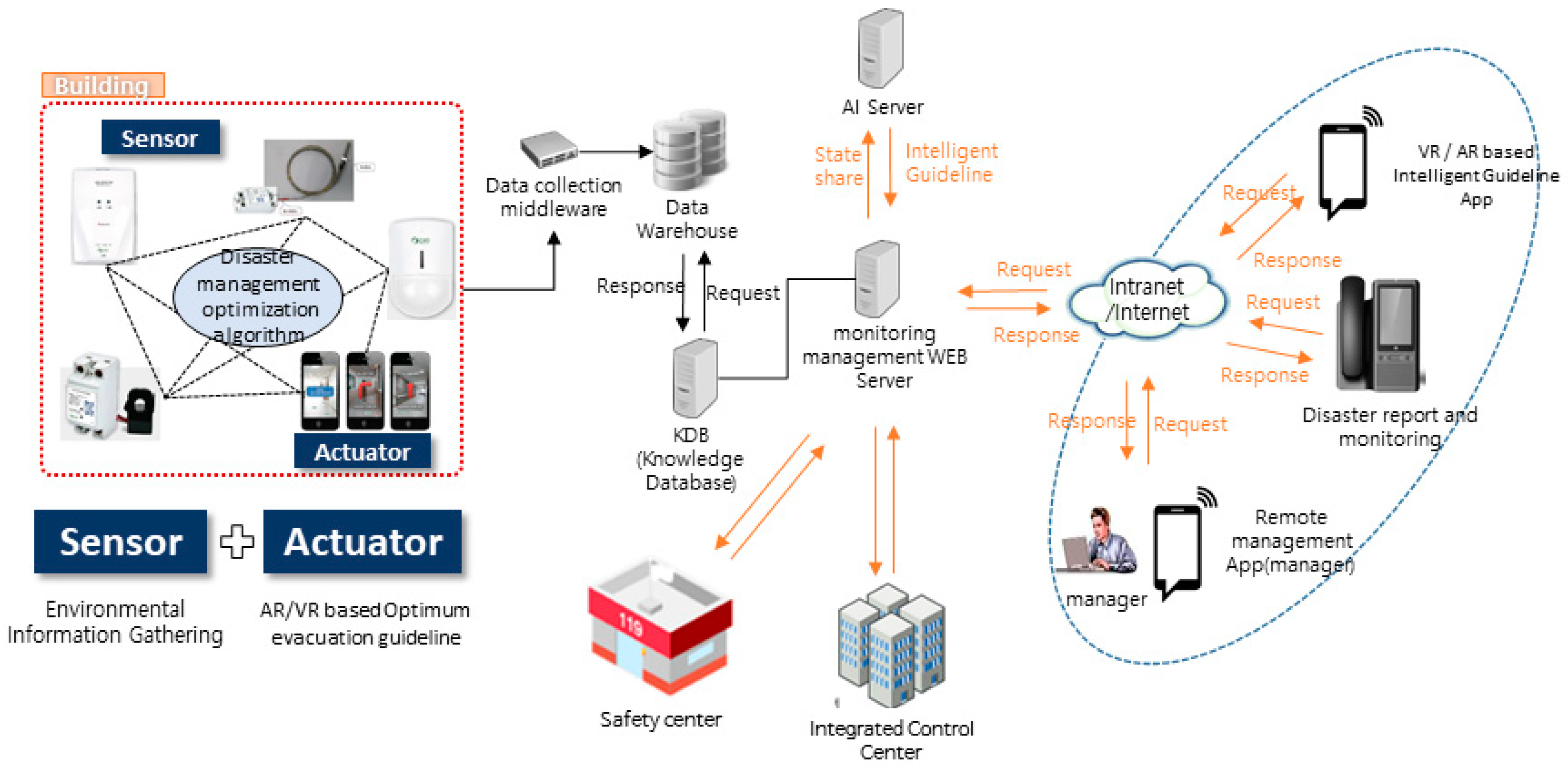
3.2. System Diagram and Components
Figure 4 shows the system diagram and components of the proposed system. The proposed system is composed of sensors and actuators in a building, monitoring management WEB server, knowledge database, data warehouse, and AR-based intelligent guideline applications, etc. Through the sensors in the building, the monitoring server gathers information resources required for the information layer.
The data (temperature, gas, CO2, fine dust, smoke) gathered from the sensor is stored in the big data server, and the AI server recognizes the building information and determines the current user information and user behavior state. The proposed system produces context awareness-based fire detection service through the intelligent data analysis and provides optimum fire escape guidelines through analyzing optimum evacuation space. The system controls the integrated control of the fire situation through real-time fire information transmission and situation analysis in conjunction with the integrated control system and the safety center. In the integrated control system, it manages the overall integrated management such as sensor information in buildings, evacuation site management by disaster, and fire situation detection through analysis of situation analysis. The safety center infrastructure manages real-time traffic situation to control the location of fire trucks and allows quick movement through real-time fire information. A summary of the system is as follows:
Real-time environmental information monitoring: ICT/IoT based real-time fire situation monitoring and AR-based optimum evacuation guideline by intelligent sensor connection;
Provides the smart building disaster management service by intelligent connection between sensors, actuator, gateway, and server.
3.3. Smart Fire Extinguish and Fire Escape Guidance Algorithm
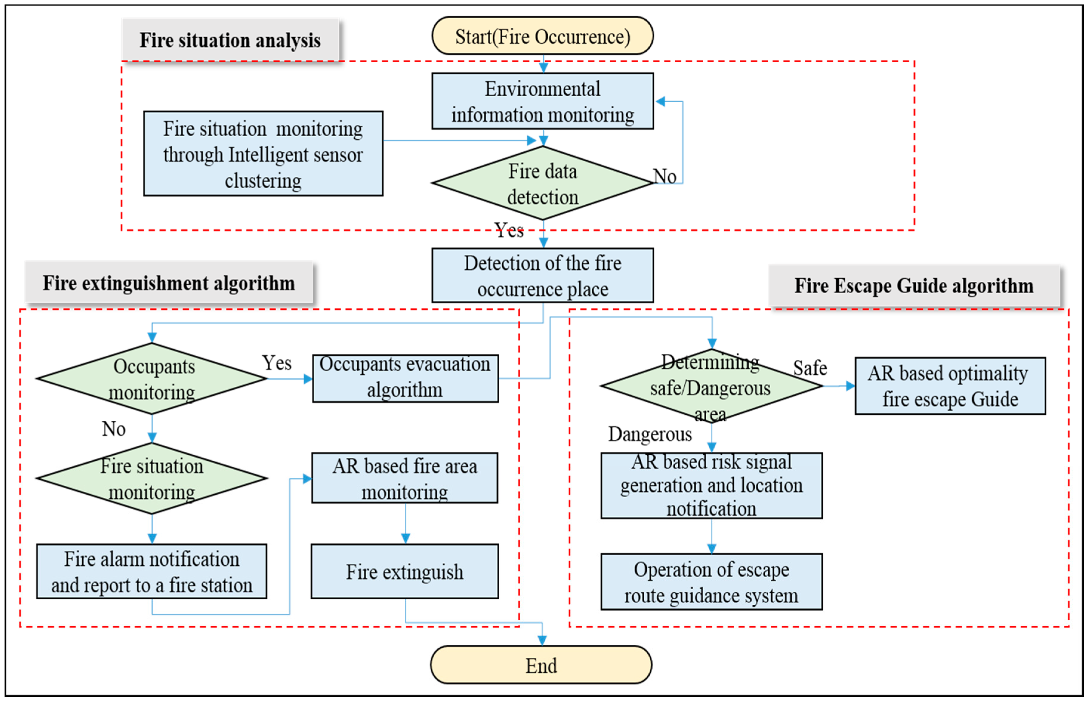
Figure 5 shows fire extinguish and fire escape guidance algorithm in the disaster management system. When a fire occurs, the smart sensors monitor the fire and detect fire situation information. Sensors send the location of fire occurrence and fire situation information to the server and the system executes the fire extinguishment through the algorithm. If there is no occupant in the building, it immediately reports the fire alarm and fire occurrence information to the fire department. Subsequently the system monitors and extinguishes the fire. If there is an occupant, it determines the safe and dangerous area, and then the occupants are safely evacuated through the fire escape guide algorithm.
4. Control Scenarios
In this chapter, we show the total flow chart of the service scenario and the four service packages about the fire extinguish process. The chapter of the total flow chart of service shows the scenarios of each stage from the occurrence of the fire to the extinguishment and the chapter of the service packages introduces the four major services that are essential for the proposed system.
4.1. Main Service Scenario
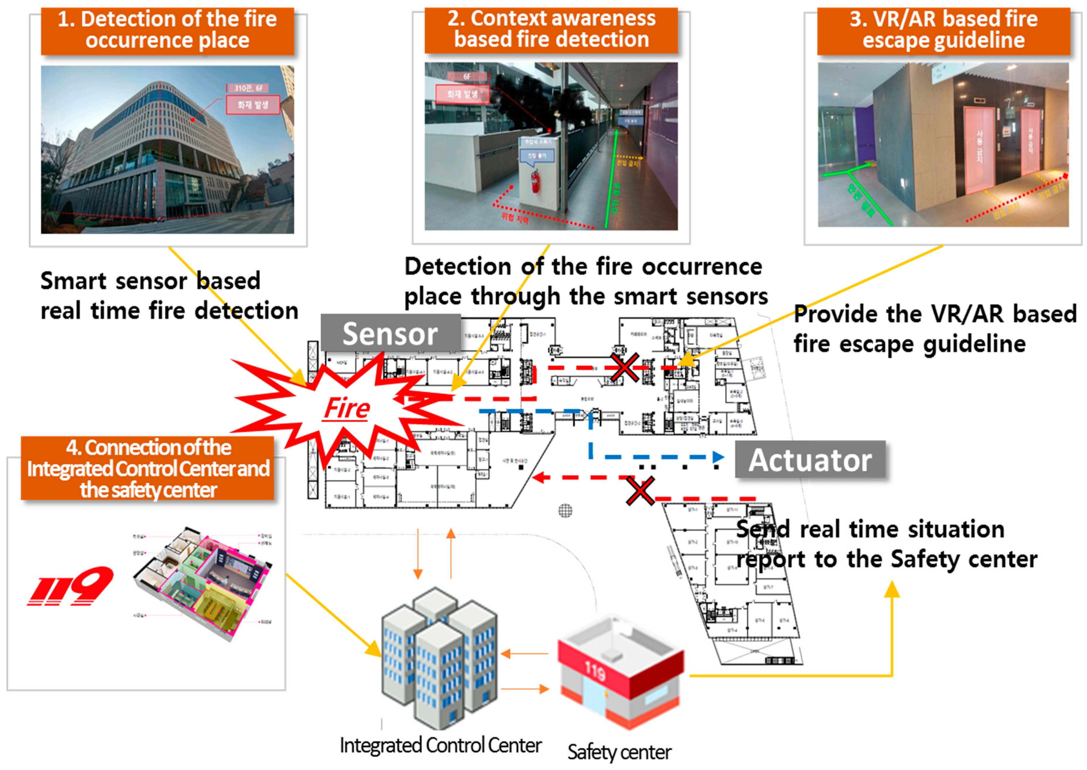
Figure 6 shows the outline of four significant scenarios. The description below gives a rough description of the service scenarios:
Detection of the Fire Occurrence Place: Real-time ignition detection service package by smart sensors detect fire point and provides real-time AR-based fire occurrence monitoring service to users, administrators, and rescuers;
Context Awareness and Actuator Control-Based Fire Detection: This is an actuator control service package through detection of fire occurrence. When a fire is detected, it shuts down gas and electricity which can further enlarge the fire;
AR-Based Fire Escape Guideline Service: Provides safe evacuation and rescue guidelines to rescuers and fire fighters through fire status information detected by human detection sensors and smart sensors;
Connection of Integrated Control Center and Safety Center: Provides services for rapid reporting and real-time monitoring to fire stations and control centers after a fire occurs.
4.2. Total Flow Chart of Service
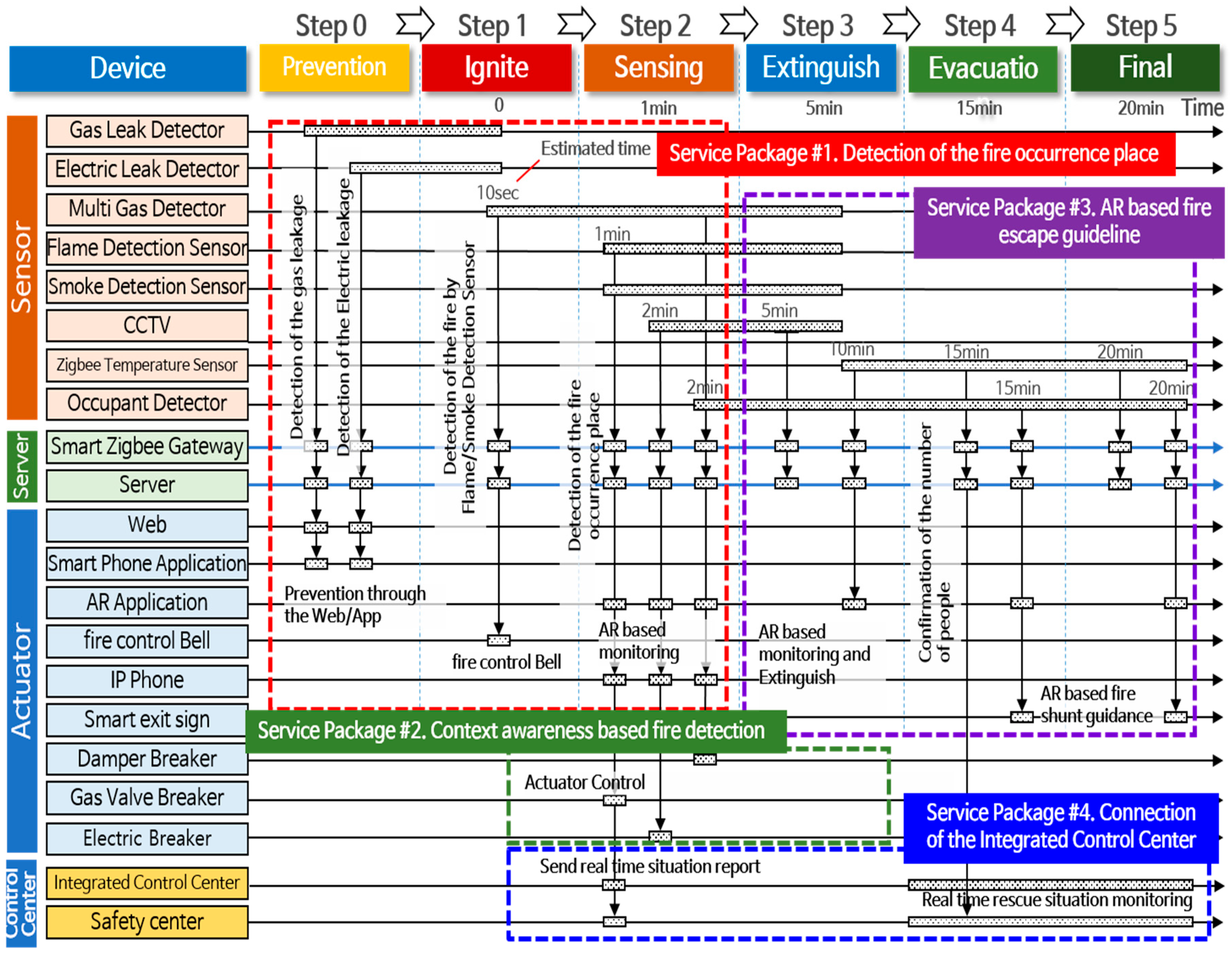
Figure 7 shows a flow chart of the scenario of the whole system. The system flow chart consists of six steps (step 0 to step 5). Each step shows the fire extinguish process according to the time from the ignition stage to the extinguishment stage of the fire in the building. One of the advantages of the proposed system is that it performs extinguishment procedures on these steps. In other words, when a fire occurs, the device is to be prepared for the failure of the device due to fire. The bar shown in
Figure 7 indicates the life expectancy of each device in case of fire. From the first stage of the fire to the extinguishment stage, this system is designed to facilitate fire evacuation and rescue. As shown in
Table 4, the entire system is operated by sensors, servers, and actuators at each step. The environmental information obtained from the smart sensors is transmitted to the server through the Smart ZigBee Gateway. When a fire occurs in the building, the server sends the state information to the user and the manager through the actuator. The manager monitors the information on the fire situation and immediately reports to the fire department.
The following is a detailed description of each service package.
4.2.1. [Service Package #1] Detection of the Fire Occurrence Place
Figure 8 and
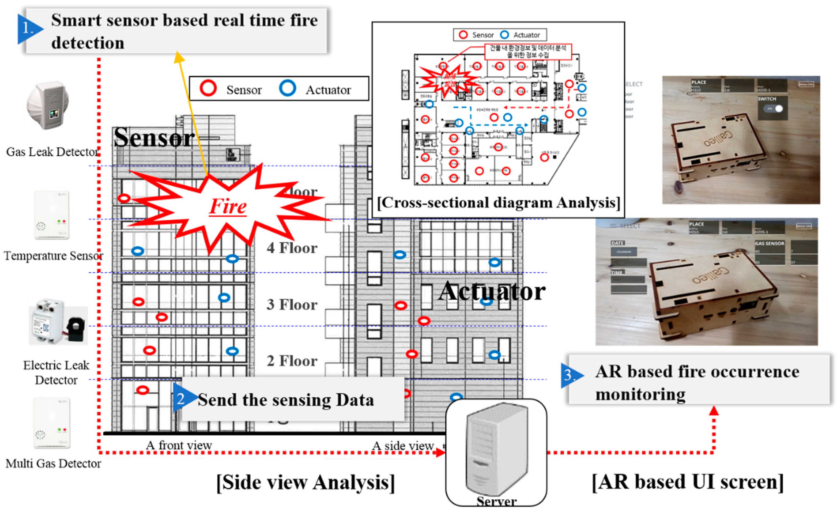
Table 5 show a real-time fire detection package by smart sensors, which detects fire points from smart sensors and provides real-time AR-based fire occurrence monitoring service to users, administrators, and rescuers. The following describes each step in detail:
Smart sensor-based real time fire detection: Collecting real-time information from smart sensors, including gas leak detector sensors, temperature sensors, electric leak detector sensors, and multi-gas detector sensors, which monitor the fire in real time and report the situation to the server immediately when a fire is detected from the smart sensor;
Send the sensing data: Real-time sensing data is transmitted to the server through Smart ZigBee gateway;
AR-based fire occurrence monitoring: Sensing data sent to the server is processed through a collection and analysis algorithm model, and displays the location information of sensor data, status information, etc. on the AR-based user interface (UI) screen of smart phones, smart pads, and so on. Users, administrators, and rescuers identify evacuation and rescue guidelines through this AR-based UI screen so that they can be safely rescued.
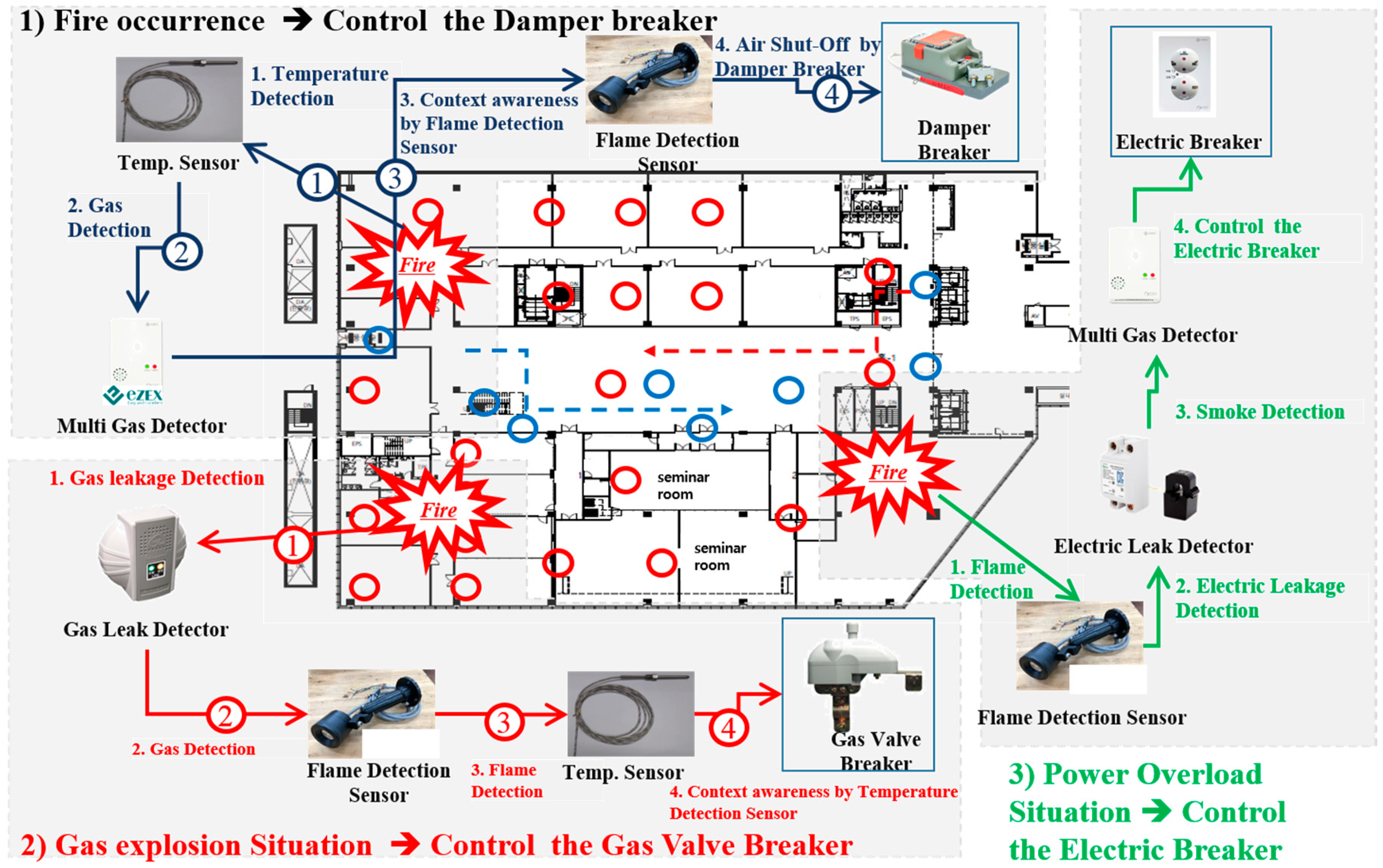
4.2.2. [Service Package #2] Context Awareness and Actuator Control-Based Fire Detection
Figure 9 and
Table 6 show an actuator control package through detection of fire occurrence. When a fire is detected, the package blocks gas and electricity which cause fire. The following shows each step:
Fire occurrence situation: This step blocks the damper when a fire is detected. First, the temperature sensor detects the temperature rise due to fire. Second, the gas sensor detects the gas from the fire. Third, the flame sensor detects whether a fire is caused by a fire, detects the occurrence of a fire, and cuts off the air supply through damper interception;
Gas explosion situation: This step shuts off the gas valve when detecting the occurrence of fire due to gas explosion. The gas leak detection sensors will discern whether there has been a gas leak. When a fire occurs due to a gas leak, the flame detection sensor and temperature sensor detect this. After transmitting the status information to the server, the server cuts off the gas supply through the gas valve breaker;
Power overload situation: This step cuts off electricity when detecting the occurrence of fire due to power overload. The flame detection sensor and integrated gas sensor detect and occurrence of a fire, and the electric leakage detection sensor detects a short circuit. The sensor detects whether a fire has occurred, transmits the status information to the server, and then server then cuts off the electricity supply through an electric breaker.
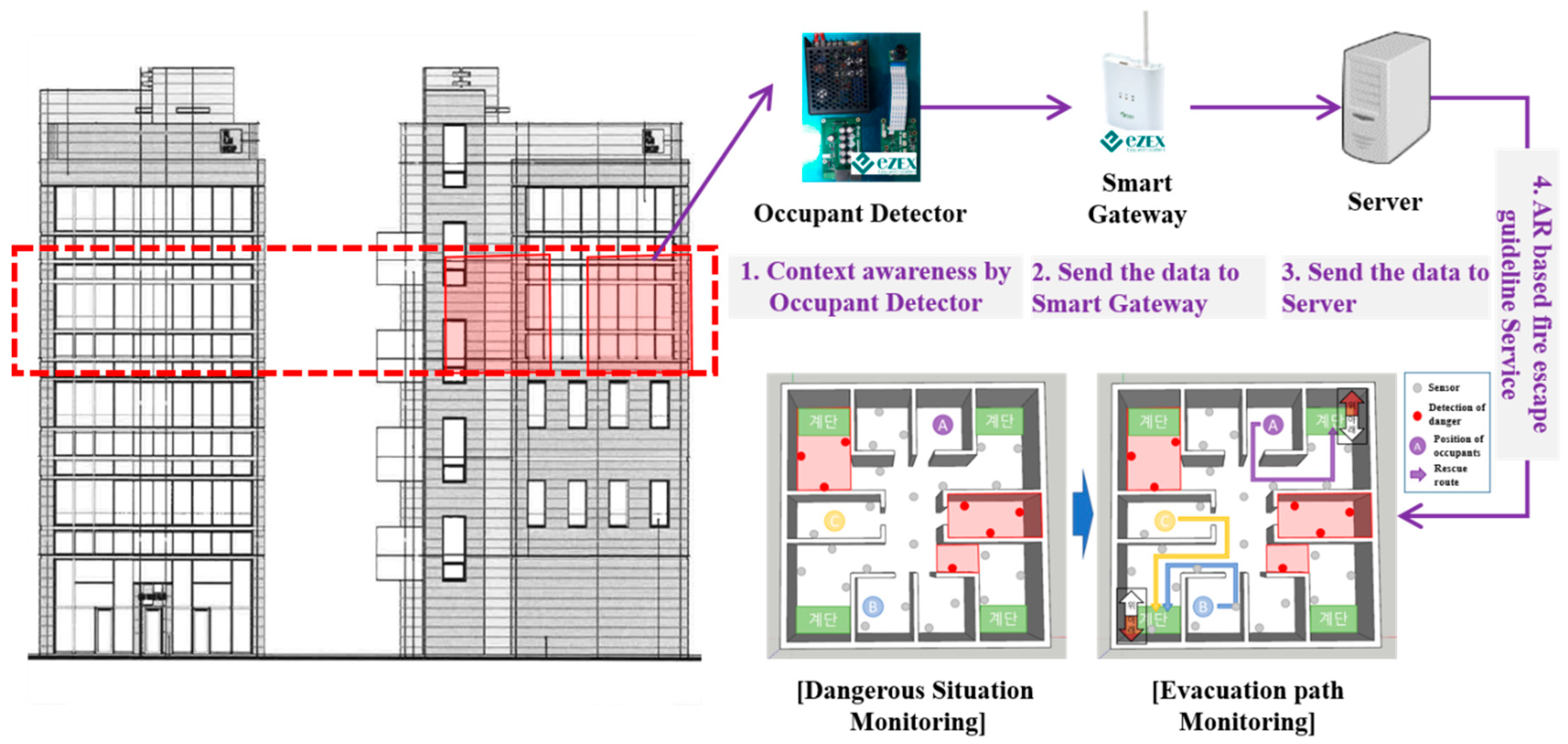
4.2.3. [Service Package #3] AR-Based Fire Escape Guidelines Service
Figure 10 and
Table 7 show a package that provides safe evacuation and rescue guidelines to occupants and rescuers through fire status information detected by smart sensors. The following shows each step:
Occupant: Provides safe evacuation location guidelines. After detecting the location of the fire from the smart sensor and transmitting it to the server, the server provides AR-based optimal guides to the occupants through smart phones and smart pads;
Rescuer: Provides the rescuer with the best rescue guidelines for the quick and safe rescue of the occupants. The location and status information of the occupants are collected from the smart sensor and transmitted to the server. The server informs the rescuer of the location of the occupants and provides the optimal rescue guidelines for safety.
4.2.4. [Service Package #4] Connection of the Integrated Control Center and the Safety Center
Figure 11 and
Table 8 show a package that provides services to enable rapid reporting and real-time monitoring to fire stations and control centers after a fire occurs. The following shows each step:
Fire occurrence reporting step: The server of each building that has collected the fire occurrence information recognizes the status and immediately reports to the safety center if the building manager cannot respond;
Fire occurrence monitoring and dispatch step: The safety center receives the report, monitors the fire situation in real time, and dispatches fire engines immediately;
Real-time fire monitoring step: The integrated control center monitors the fire situation in real time and continuously provides information on the fire situation to the rescuer;
Arrival and rescue step of fire area: The rescuer arrives at the fire area and rescues the occupants through AR-based smart building disaster management service of smart phones and smart pads.
5. Implementation and Results
The following is a chapter on the actual implementation of the proposed system. In this paper, a small test-bed was designed and implemented for interlocking and interoperability test of the system between system devices.
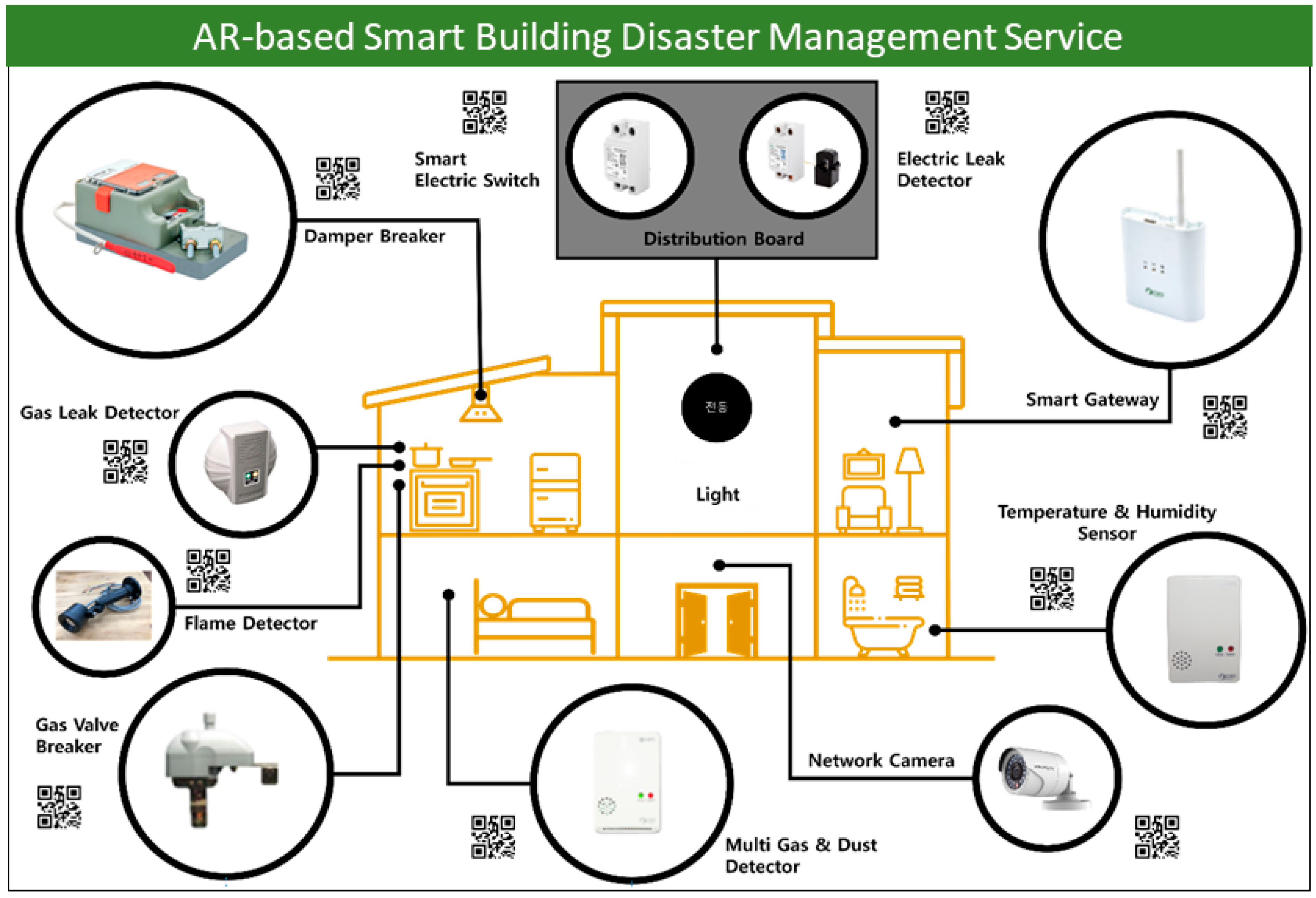
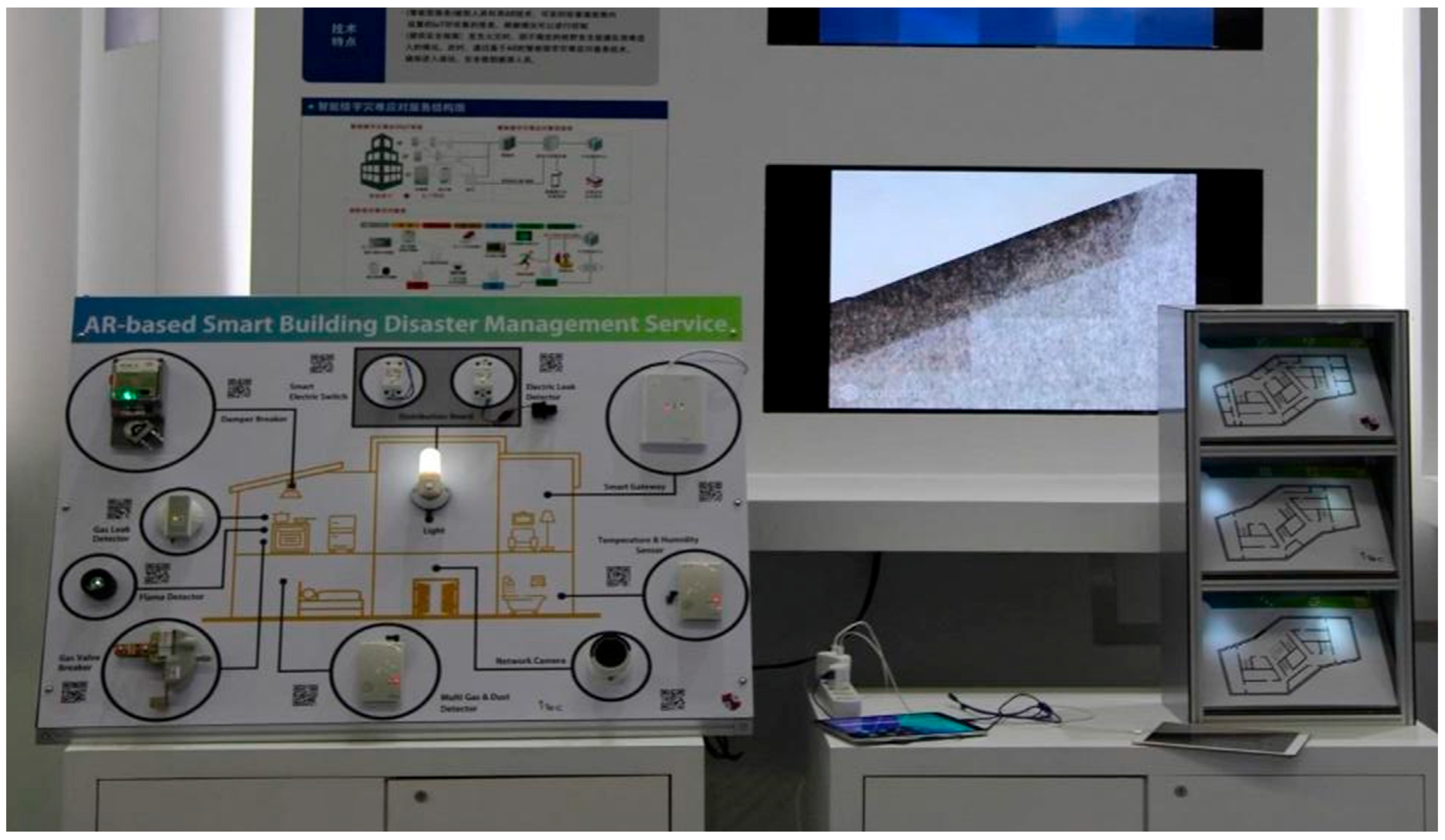
Figure 12 shows an AR-based smart building disaster management service system board. A total of 10 system devices are installed on the board. There were electronic leak detectors, temperature and humidity sensors, network cameras, multi gas and dust detectors, flame detectors, gas leak detectors, a damper breaker, distribution board, and a gas valve breaker installed in a board and data was transmitted by the smart gateway. A Quick Response (QR) code was embedded in the side of each device, and it provided the monitoring and control interface for status information representation and actuator control through device self-recognition or QR code recognition on smart pad.
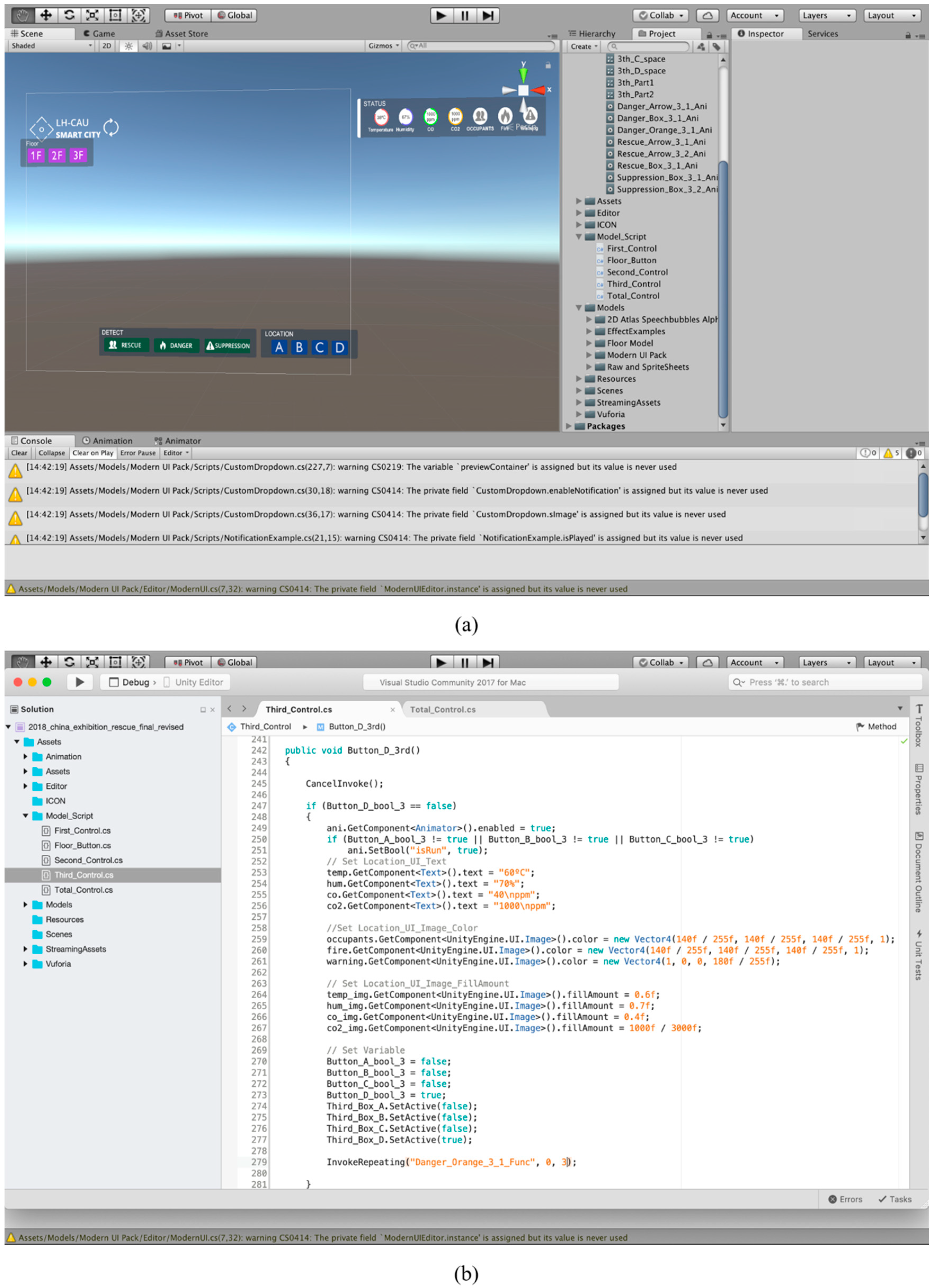
Figure 13 shows the AR-based application development tool “Unity” and
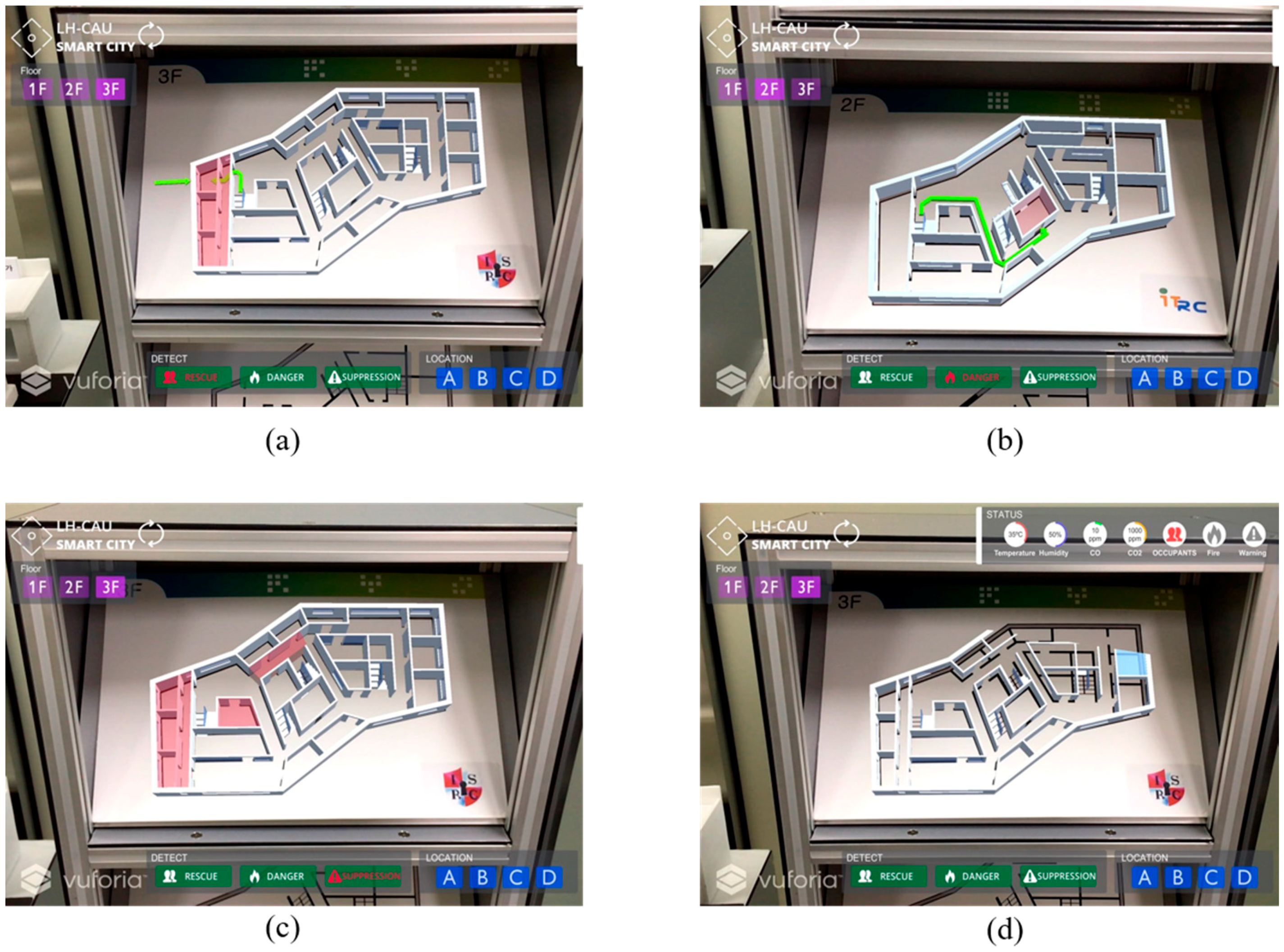
Figure 14 shows the AR-based fire situation guideline simulation UI screen of the proposed system developed by the Unity tool.
Figure 14a is a simulation UI screen of the AR based safe path guideline for rescuers, and
Figure 14b,c shows the UI screen that monitored the building room information and fire hazard area.
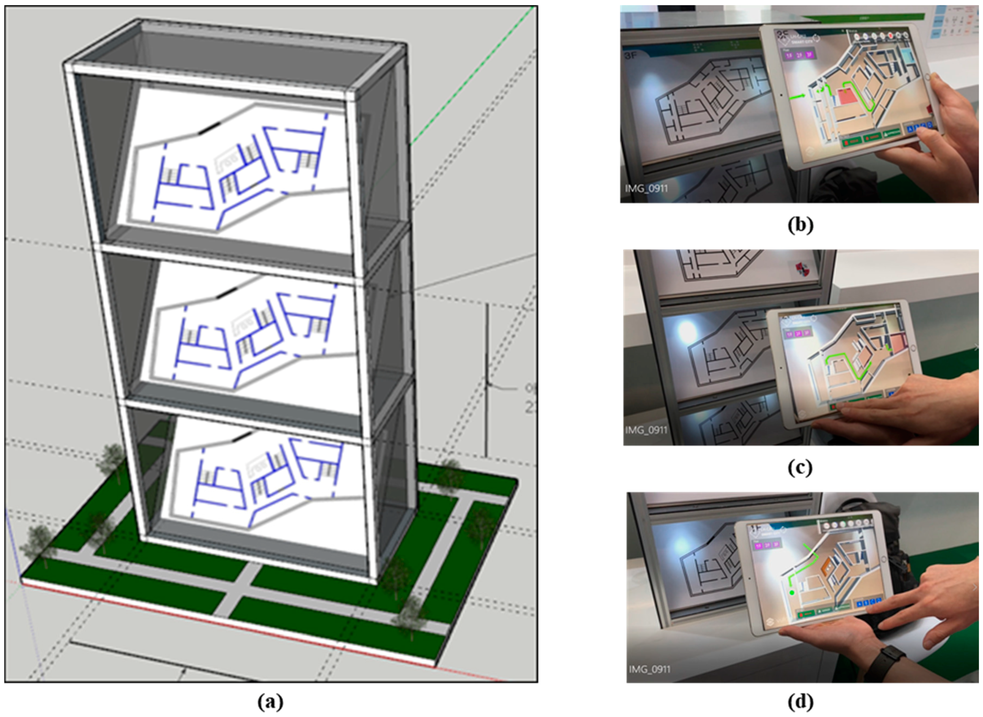
The following
Figure 15 shows the Smart Building Model. The purpose of this model is to provide evacuation guideline service to the occupants and rescuers by scanning the building structure using smart pads in case of fire inside the building (
Figure 16). The Smart Building Model consists of scenarios for reacting and resisting from fire in actual buildings, and it can be verified with AR-based virtual building model motion simulation. As shown in
Figure 13, the rescuers can run the AR-based Smart Building Disaster Management Service application and click on the 1st floor to 3rd floor drawings to view the floor plans, identify the fire point and the danger area, and confirm the location of the refuge persons. They can check the rescue route and the situation information according to the location of the refuge person when clicking on the refuge person. Through this system, victim rescue and fire suppression can be done within a short time by providing evacuation and rescue guides most suitable for occupants and rescuers.
Table 9 shows the device specifications implemented in the AR-based Smart Building Disaster Management System.
Figure 14 shows the actual implementation picture of this system board and Smart Building Model.
The following subsection shows system operation steps of the occupants and rescuers.
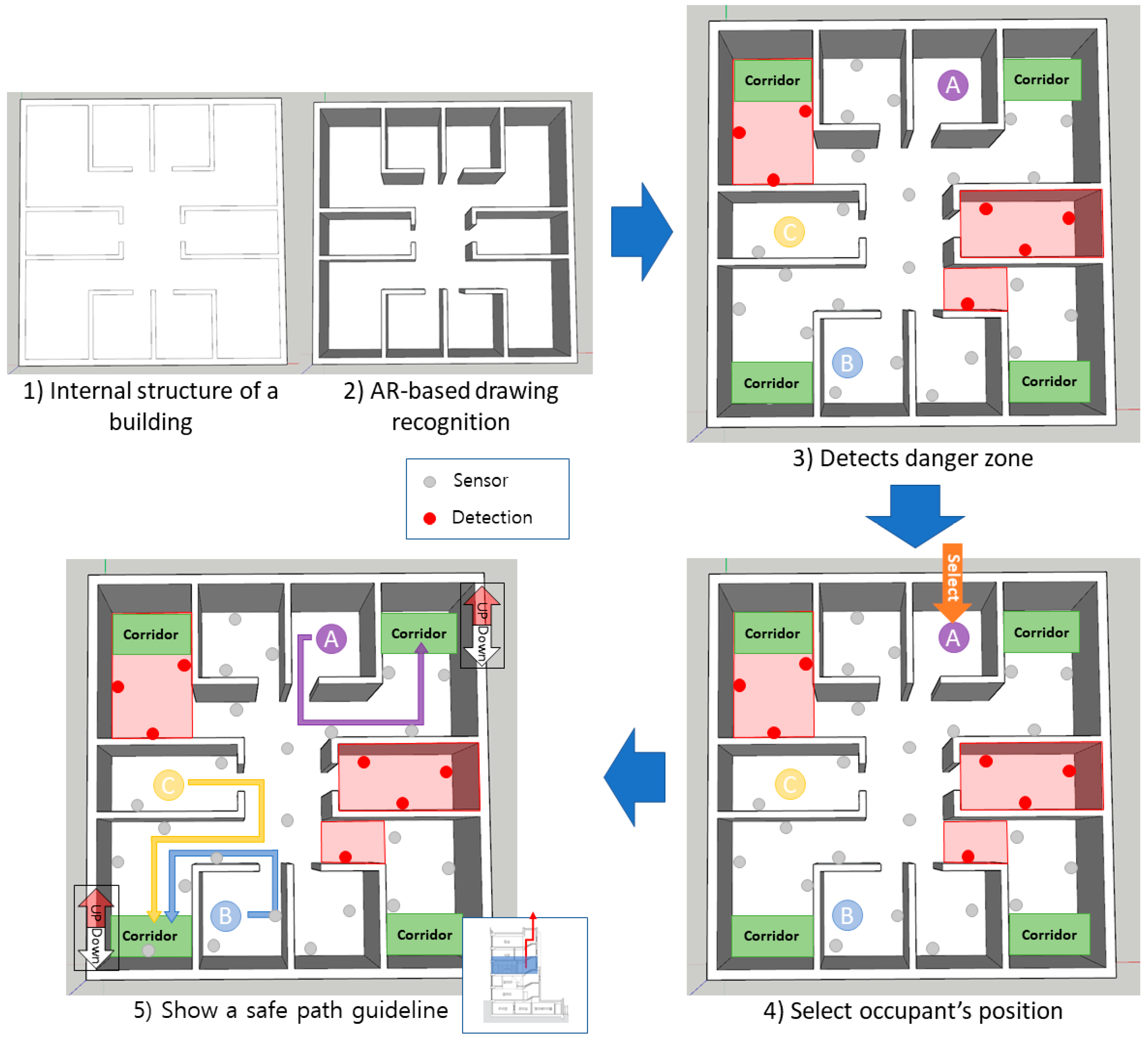
5.1. Occupant’s Optimal Evacuation Route
• System operation step: (1) internal structure of a building → (2) AR-based drawing recognition → (3) detects danger zone → (4) select occupant’s position → (5) show a safe path guideline
Figure 17 shows the system operation for occupants. Assuming a fire situation, the occupants quickly execute the AR-based Smart Building Disaster Management Service application and recognize the drawing of the building (building structure recognition in real situations) through the camera. The fire occurrence area is recognized by the smart sensor and displayed on the application screen based on the AR. The position of the occupants recognized by the smart sensor is displayed and its position is selected. A safe evacuation route from the selected occupant location to the exit is recommended and displayed on the smart pad screen.
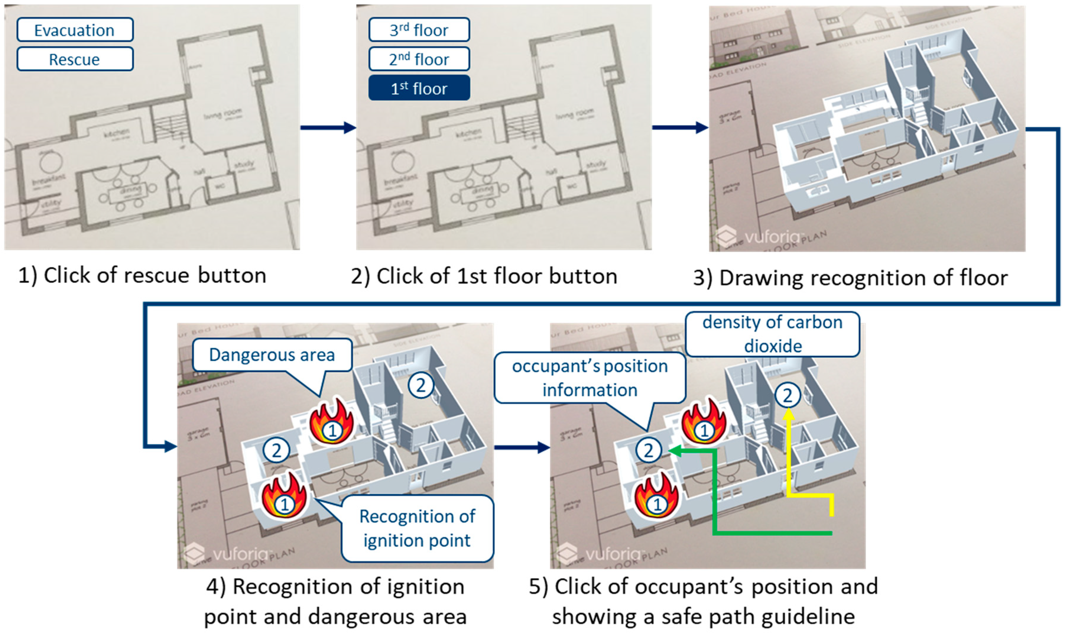
5.2. Rescuer Rescue Guide
• System operation step: (1) click on rescue button → (2) click on 1st floor button → (3) drawing recognition of floor → (4) recognition of ignition point and dangerous area → (5) click on occupant’s position and suggests a safe path guideline
Figure 18 shows system operation for rescuer. Assuming a fire situation, the rescuer quickly launches the AR-based Smart Building Disaster Management Service application and clicks the Rescue button. The rescuer will then click on the drawing of the floor where the occupant is to be rescued and recognizes the drawing of the building (structure recognition of the building in real situations) through the camera. The abnormal area and the fire occurrence area are recognized by the smart sensor and displayed on the application screen based on the AR. The position of the occupants to be rescued is identified by the room sensor and the position of the structure is selected. The recommended rescue path for occupants is suggested and displayed on the smart pad screen.
5.3. Discussion
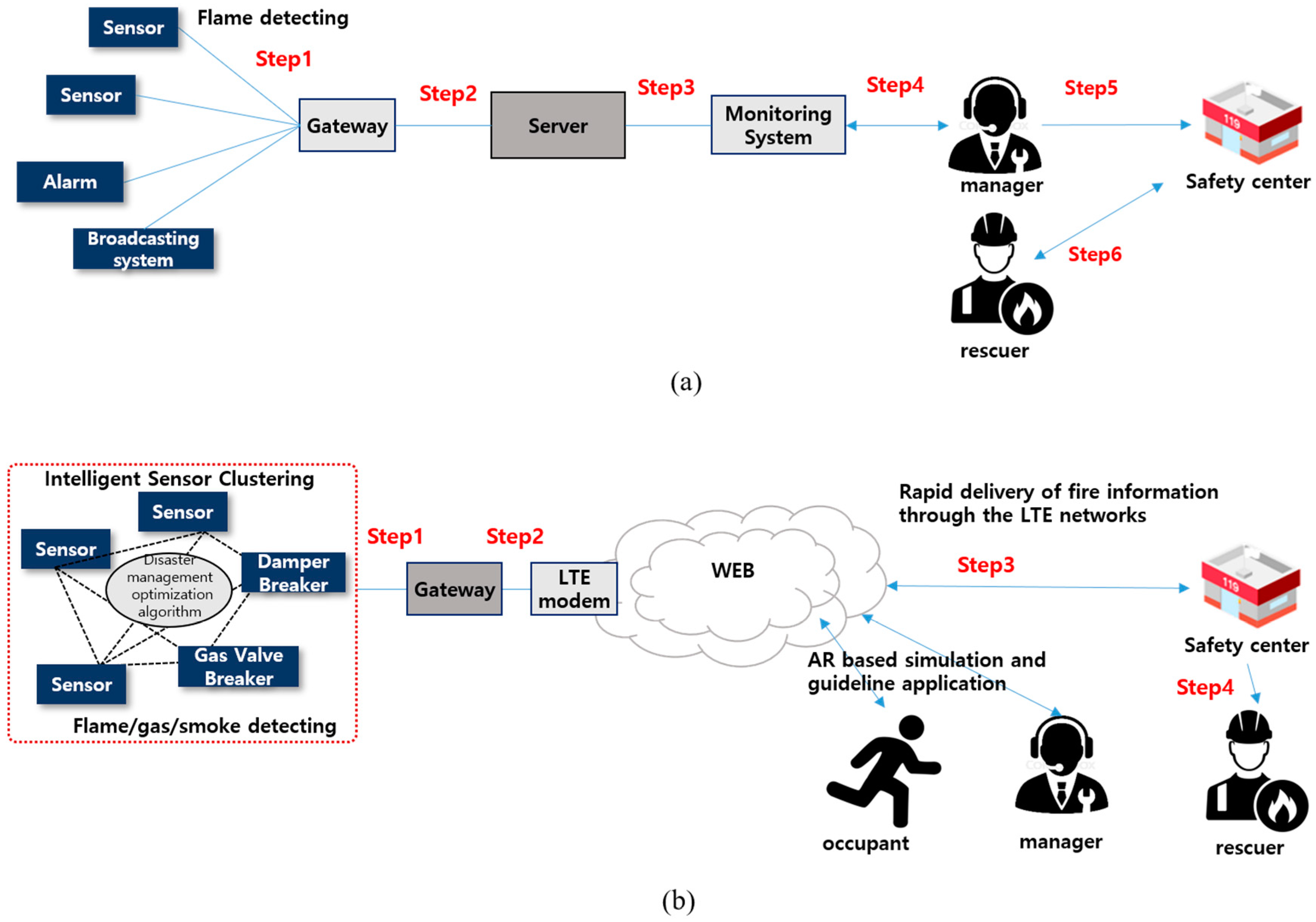
We derive predicted results such as the improvement of the CPU transfer rate through the sensor clustering, user satisfaction, and extinguishment and evacuation time comparison between the proposed system and the existing system. The existing system is operated through the Building Automation System (BAS) based sprinkler, alarm, and evacuation speaker guide system. When heat was detected through a fire or a heat detector, water was sprayed through the sprinkler and the alarm was informed. In addition, the building manager was to report to the safety center when the fire was detected. But the proposed system is operated through the context aware based fire situation detection by the sensor clustering and controls the actuator according to the fire situation. In particular, our system is based on the LTE network and immediately informs the fire situation to the manager and safety center. In addition, rapid and accurate rescue is possible through AR based real-time monitoring and guidance system.
Figure 19 shows the system diagram of the existing system and the proposed system. And
Table 10 shows the connection formation for each step of the existing and proposed system.
In
Table 10, the existing system consists of six steps, from the occurrence of the fire to the extinguishment and evacuation. However, the proposed system transmits the fire information based on the long term evolution (LTE) network, the fire situation is communicated to the manager and safety center simultaneously. And since the gateway transmits the fire information to the users through the LTE network directly without going through the server, it is possible to transmit the fire information quickly. As
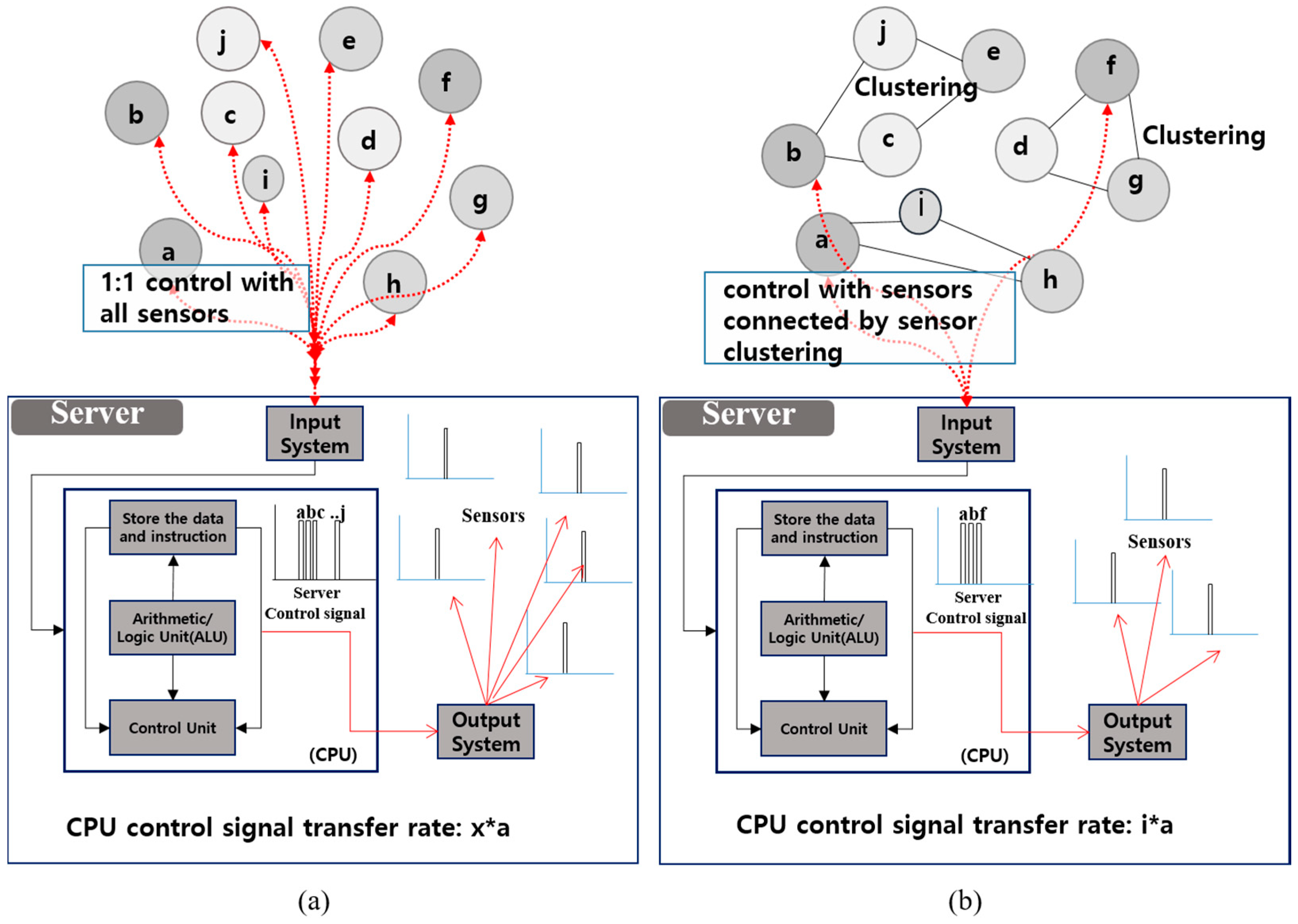
Figure 20, the existing system transmits the information through the 1:1 structure of the sensor with the server. However, the proposed system transmits the information through the sensor clustering based 1:n structure, and it can be predicted that the proposed system is more efficiency of the CPU performance. The
Table 11 is the analysis of the difference between the existing system and the proposed system.
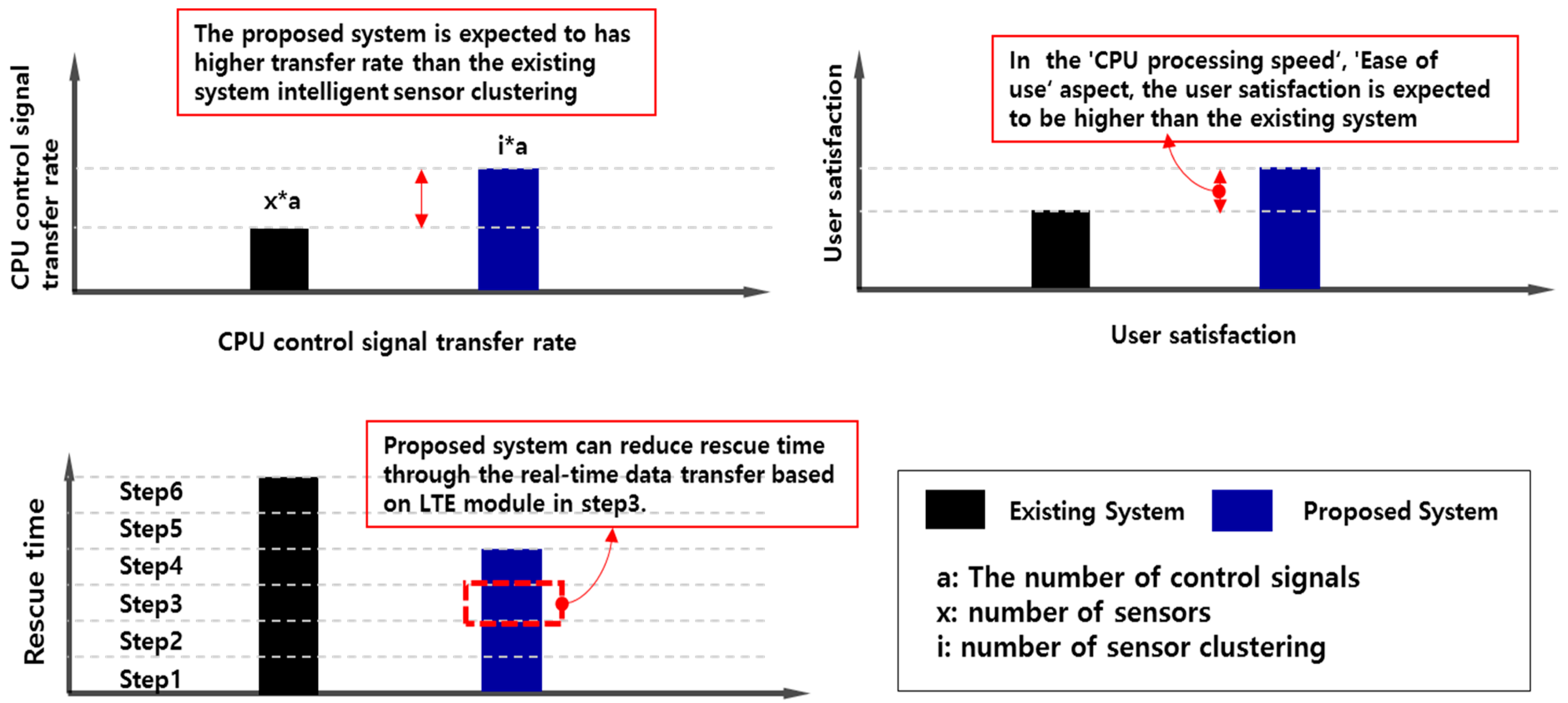
As shown in
Figure 21, we derived the results about the CPU processing, user satisfaction, and extinguishment and evacuation time. User satisfaction is derived based on the Software Adequacy, Software maintenance, Information accuracy, Ease of use, Timeliness, Security and Integrity as shown in [
20]. In the “CPU processing speed”, and “Ease of use” aspect, and user satisfaction is expected to be higher than the existing system as shown in
Table 11. Also the total extinguishment and evacuation time is derived that the proposed system is more rapid than the existing system as mentioned above.
6. Conclusions and Future Perspective
In this paper, we propose the AR-based Smart Building & Town Disaster Management System to solve problems as the fire accidents caused by the fire in urban areas have become larger. Most buildings in Korea are taller than two floors, so the proposed service is expected to reduce the risk of large damages and many casualties. Additionally, it is possible to safely rescue occupants by securing a clear view for users guiding a safe direction through AR-based technologies.
We implemented this system in a small test-bed and established an AR-based smart building disaster management service system board installed in a total of 10 system devices (electric leak detectors, temperature and humidity sensors, network cameras, multi gas and dust detectors, flame detectors, gas leak detectors, damper breaker, distribution board, and gas valve breaker). Additionally, we composed the Smart Building Model to simulate the AR-based system providing an evacuation guideline service to the occupants and rescuers by scanning the building structure using smart pads in case of a fire inside the building. We implemented the actual system operation by this system board and Smart Building Model. However, this implementation was just a simulation test performed in a small test-bed, therefore, this research will be further studied in the future through application to real smart building and smart city test-beds through various location-based technologies such as building information modeling (BIM), geographic information system (GIS), and radio-frequency identification (RFID) etc. in the future. Through this study, it is expected that it will play an integral role in smart building and smart city domains [
21,
22,
23,
24].
The following notes the novelty and differentiation of the proposed system:
Intelligent service: AR technology provides rapid structure and evacuation simulation and guidance reflecting the characteristics and environment of buildings and areas in smart city through linkage of physical and virtual domain in the building;
Safety Guideline: Provide safe guideline services to occupants and rescuers in the event of actual fire;
IoT-based real-time remote system: IoT-based remote system capable of quick response in connection with fire department through providing real-time fire occurrence information.
Therefore, the improvement of national competitiveness in security and safety in smart buildings, and the expansion of industry and promoting employment through linkage and integration by building elements of smart safety field are expected. Through this research, we are making efforts to realize cyber physical system (CPS) and digital twin technology based on Smart-IoT, AI, big data, and further realizing smart cities.
Author Contributions
System Modeling: S.P. (Sanguk Park), S.P. (Sangmin Park), L.W.P., T.L. and S.L., Management System Implement: S.H.P., H.J., S.H.L. and S.M.K., Review and Editing: S.P. (Sangmin Park) and L.W.P., Supervision: S.P. (Sehyun Park), Project administration: S.P. (Sehyun Park).
Funding
This research received no external funding.
Acknowledgments
This work was supported by the Human Resources Development (No. 20184030202070) of the Korea Institute of Energy Technology Evaluation and Planning (KETEP) grant funded by the Korea government Ministry of Trade, Industry and Energy, and this research was supported by the Chung-Ang University Graduate Research Scholarship in 2017.
Conflicts of Interest
The authors declare no conflict of interest.
References
- Cavallo, A.; Ireland, V. Preparing for complex interdependent risks: A system of systems approach to building disaster resilience. Int. J. Disaster Risk Reduct. 2014, 9, 181–193. [Google Scholar] [CrossRef]
- Meissner, A.; Luckenbach, T.; Risse, T.; Kirste, T.; Kirchner, H. Design challenges for an integrated disaster management communication and information system. In Proceedings of the First IEEE Workshop on Disaster Recovery Networks (DIREN 2002), New York, NY, USA, 24 June 2002. [Google Scholar]
- Asimakopoulou, E.; Bessis, N. Buildings and crowds: Forming smart cities for more effective disaster management. In Proceedings of the 2011 Fifth International Conference on Innovative Mobile and Internet Services in Ubiquitous Computing (IMIS), Seoul, Korea, 30 June–2 July 2011; IEEE: Piscataway, NJ, USA, 2011; pp. 229–234. [Google Scholar]
- The Korea Times. Available online: http://www.koreatimes.com/article/20170614/1061005 (accessed on 12 July 2018).
- The National Fire Data Center. Available online: https://www.nfds.go.kr/fr_scls_0301.jsf (accessed on 12 July 2018).
- Dimakis, N.; Filippoupolitis, A.; Gelenbe, E. Distributed building evacuation simulator for smart emergency management. Comput. J. 2010, 53, 1384–1400. [Google Scholar] [CrossRef]
- George, S.M.; Zhou, W.; Chenji, H.; Won, M.; Lee, Y.O.; Pazarloglou, A.; Stoleru, R.; Barooah, P. Distressnet: A wireless ad hoc and sensor network architecture for situation management in disaster response. IEEE Commun. Mag. 2010, 48, 128–136. [Google Scholar] [CrossRef]
- Cutter, S.L.; Barnes, L.; Berry, M.; Burton, C.; Evans, E.; Tate, E.; Webb, J. A place-based model for understanding community resilience to natural disasters. Glob. Environ. Chang. 2008, 18, 598–606. [Google Scholar] [CrossRef]
- Heo, B.-Y.; Heo, W.-H. Economic analysis for collapse hazard areas. Appl. Sci. 2017, 7, 693. [Google Scholar] [CrossRef]
- Wagner, N.; Agrawal, V. An agent-based simulation system for concert venue crowd evacuation modeling in the presence of a fire disaster. Expert Syst. Appl. 2014, 41, 2807–2815. [Google Scholar] [CrossRef]
- Shi, J.; Ren, A.; Chen, C. Agent-based evacuation model of large public buildings under fire conditions. Autom. Construct. 2009, 18, 338–347. [Google Scholar] [CrossRef]
- Tan, L.; Hu, M.; Lin, H. Agent-based simulation of building evacuation: Combining human behavior with predictable spatial accessibility in a fire emergency. Inf. Sci. 2015, 295, 53–66. [Google Scholar] [CrossRef]
- Kantarci, B.; Mouftah, H.T. Trustworthy sensing for public safety in cloud-centric internet of things. IEEE Internet Things J. 2014, 1, 360–368. [Google Scholar] [CrossRef]
- Cheng, B.; Zhu, D.; Zhao, S.; Chen, J. Situation-aware iot service coordination using the event-driven soa paradigm. IEEE Trans. Netw. Serv. Manag. 2016, 13, 349–361. [Google Scholar] [CrossRef]
- Kanan, R.; Elhassan, O.; Bensalem, R. An iot-based autonomous system for workers’ safety in construction sites with real-time alarming, monitoring, and positioning strategies. Autom. Construct. 2018, 88, 73–86. [Google Scholar] [CrossRef]
- Hirohara, Y.; Ishida, T.; Uchida, N.; Shibata, Y. Proposal of a disaster information cloud system for disaster prevention and reduction. In Proceedings of the 2017 31st International Conference on Advanced Information Networking and Applications Workshops (WAINA), Taipei, Taiwan, 27–29 March 2017; IEEE: Piscataway, NJ, USA, 2017; pp. 664–667. [Google Scholar]
- Wafi, Z.K.; Malek, M.F.A.; Alnajjar, S.H.; Ahmad, R.B. Early warning system for disaster management in rural area. In Proceedings of the 2015 International Symposium on Technology Management and Emerging Technologies (ISTMET), Pulau Langkawi, Malaysia, 25–27 August 2015; IEEE: Piscataway, NJ, USA, 2015; pp. 369–372. [Google Scholar]
- Milgram, P.; Kishino, F. A Taxonomy of mixed reality visual displays ieice transactions on information and systems. IEICE Trans. Inf. Syst. 1994, e77-D, 1321–1329. [Google Scholar]
- Journal of Safety. Available online: https://www.anjunj.com/news/article View.html?idxno=16302 (accessed on 26 December 2018).
- Palvia, P.C. A model and instrument for measuring small business user satisfaction with information technology. Inf. Manag. 1996, 31, 151–163. [Google Scholar] [CrossRef]
- Tsirmpas, C.; Rompas, A.; Fokou, O.; Koutsouris, D.J.I.S. An indoor navigation system for visually impaired and elderly people based on radio frequency identification (RFID). Inf. Sci. 2015, 320, 288–305. [Google Scholar] [CrossRef]
- Boguslawski, P.; Mahdjoubi, L.; Zverovich, V.; Fadli, F.; Barki, H. BIM-GIS modelling in support of emergency response applications. WIT Trans. Built Environ. 2015, 149, 381–391. [Google Scholar]
- Liu, X.; Wang, X.; Wright, G.; Cheng, J.C.; Li, X.; Liu, R. A state-of-the-art review on the integration of building information modeling (bim) and geographic information system (gis). Int. J. Geo-Inf. 2017, 6, 53. [Google Scholar] [CrossRef]
- Liu, X.; Shannon, J.; Voun, H.; Truijens, M.; Chi, H.-L.; Wang, X.J.S. Spatial and temporal analysis on the distribution of active radio-frequency identification (rfid) tracking accuracy with the kriging method. Sensor 2014, 14, 20451–20467. [Google Scholar] [CrossRef] [PubMed]
Figure 1.
Recent fire accidents in buildings: (a) Jecheon sports center fire disaster in Korea; (b) apartment fire disaster in London.
Figure 1.
Recent fire accidents in buildings: (a) Jecheon sports center fire disaster in Korea; (b) apartment fire disaster in London.
Figure 2.
Status of building fire by region in Korea (1 July 2017~30 June 2018) [
5].
Figure 2.
Status of building fire by region in Korea (1 July 2017~30 June 2018) [
5].
Figure 3.
System architecture.
Figure 3.
System architecture.
Figure 4.
System diagram and components.
Figure 4.
System diagram and components.
Figure 5.
The fire extinguish and fire escape guidance algorithm.
Figure 5.
The fire extinguish and fire escape guidance algorithm.
Figure 6.
AR-based smart building and town disaster management main service packages.
Figure 6.
AR-based smart building and town disaster management main service packages.
Figure 7.
Total flow chart of service.
Figure 7.
Total flow chart of service.
Figure 8.
Detection of the fire occurrence place.
Figure 8.
Detection of the fire occurrence place.
Figure 9.
Actuator control-based fire detection service package.
Figure 9.
Actuator control-based fire detection service package.
Figure 10.
AR-based fire escape guideline service.
Figure 10.
AR-based fire escape guideline service.
Figure 11.
Connection of the integrated control center and the safety center.
Figure 11.
Connection of the integrated control center and the safety center.
Figure 12.
AR-based smart building disaster management service system board.
Figure 12.
AR-based smart building disaster management service system board.
Figure 13.
Unity, AR software development tool screen: (a) “Unity” Development Software; (b) Source Code Development of the Proposed Solution.
Figure 13.
Unity, AR software development tool screen: (a) “Unity” Development Software; (b) Source Code Development of the Proposed Solution.
Figure 14.
AR-based fire situation guideline screen UI: (a,b) AR based Safe Path Guideline UI; (c) Recognition of Dangerous Area; (d) Room Information View.
Figure 14.
AR-based fire situation guideline screen UI: (a,b) AR based Safe Path Guideline UI; (c) Recognition of Dangerous Area; (d) Room Information View.
Figure 15.
Implementation Model: (a) Smart Building Model; (b) System operation UI (3rd floor); (b) system operation UI (2nd floor); (c) system operation UI (2nd floor); (d) system operation UI (1st floor).
Figure 15.
Implementation Model: (a) Smart Building Model; (b) System operation UI (3rd floor); (b) system operation UI (2nd floor); (c) system operation UI (2nd floor); (d) system operation UI (1st floor).
Figure 16.
Figure of the system board and the smart building model.
Figure 16.
Figure of the system board and the smart building model.
Figure 17.
System operation for occupants.
Figure 17.
System operation for occupants.
Figure 18.
System operation for rescuer.
Figure 18.
System operation for rescuer.
Figure 19.
Diagram of the existing system and proposed system: (a) The Diagram of Existing System; (b) The Diagram of Proposed System.
Figure 19.
Diagram of the existing system and proposed system: (a) The Diagram of Existing System; (b) The Diagram of Proposed System.
Figure 20.
The CPU control signal about the sensor to server connection (a: The number of control signals, x: number of sensors, i: number of the sensor clustering): (a) Existing System; (b) Propose System.
Figure 20.
The CPU control signal about the sensor to server connection (a: The number of control signals, x: number of sensors, i: number of the sensor clustering): (a) Existing System; (b) Propose System.
Figure 21.
Result of the proposed system.
Figure 21.
Result of the proposed system.
Table 1.
Statistics on personal injury by fire cause in Korea (1 July 2017~30 June 2018) [
5].
Table 1.
Statistics on personal injury by fire cause in Korea (1 July 2017~30 June 2018) [
5].
| Classification | Number | Ratio (%) |
|---|
| Total | 2645 | 100 |
| Toxic Gas Inhalation | 786 | 29.72 |
| Toxic Gas Inhalation and Burn | 304 | 11.49 |
| Burn | 913 | 34.52 |
| Falling or Slipping | 66 | 2.5 |
| Building Collapse | 6 | 0.23 |
| Falling during Evacuation | 35 | 1.32 |
| Confinement | 3 | 0.11 |
| Laceration | 57 | 2.16 |
| Complex Cause | 50 | 1.89 |
| Unknown | 309 | 11.68 |
| Others | 116 | 4.39 |
Table 2.
The number of fire engines arriving at the site in Korea in 2018 [
5].
Table 2.
The number of fire engines arriving at the site in Korea in 2018 [
5].
| Classification | Within 5 min | Within 10 min | Within 20 min | Within 30 min | Within 1 h | One Hour or More |
|---|
| Sum | 14,799 | 7763 | 3190 | 327 | 93 | 17 |
Table 3.
Differences with the existing system.
Table 3.
Differences with the existing system.
| Current System | Proposed System |
|---|
Current disaster management system through augmented reality (AR) technology is mostly focused on education and experiential technology There are few systems for rapid construction, simulation, and guiding for evacuation in smart buildings No remote management system based on AR and IoT, which can cope with the real fire department No appropriate alternative as the systematic destruction by the fire progresses
| Providing a service that provides a safe rescue by providing guiding residents in case of actual fire AR technology provides rapid rescue, evacuation simulation, and guidance The IoT-based remote system capable of quick response in connection with the fire department through providing real-time fire occurrence information Providing an appropriate method from system destruction by the fire progressing
|
Table 4.
Sensor and actuator in the service step.
Table 4.
Sensor and actuator in the service step.
| Step | Description | Sensor | Server | Actuator |
|---|
| Cognitive Sensor | Extinction Sensor |
|---|
| Prevention | | Smart Gas Leakage Sensor electric leak detector
| - | Smart Zigbee Gateway Server
| Web Smart Phone Application
|
| Ignite | | | Smart Gas Leakage Sensor electric leak detector
| Smart Zigbee Gateway Server
| |
| Sensing | Ignition progression step As the ignition progresses, flame detection and smoke detection, ignition progress monitoring through CCTV and personnel detectors
| Multi Gas Detector Flame Detection Sensor Smoke Detector CCTV Occupant Sensor
| - | Smart Zigbee Gateway Server
| AR Application IP Phone Damper Breaker Gas Valve Breaker Electric Breaker
|
| Extinguish | | Flame Detection Sensor Smoke Detector CCTV Temperature Sensor Occupant Sensor
| Multi Gas Detector Flame Detection Sensor Smoke Detector CCTV
| Smart Zigbee Gateway Server
| |
| Evacuation | | Temperature Sensor Occupant Sensor
| - | Smart Zigbee Gateway Server
| AR Application Smart exit sign
|
| Final | | Temperature Sensor Occupant Sensor
| - | Smart Zigbee Gateway Server
| AR Application Smart exit sign
|
Table 5.
Service Package #1 details of the scenario.
Table 5.
Service Package #1 details of the scenario.
| Service | Details of the Scenario |
|---|
IoT sensor value monitoring to detect fire location
—Building section analysis | Service details: AR-based sensor data monitoring for fire detection and fire risk identification in case of fire Service main target: Rescuer, occupants, integrated control manager Service domain: Smart home/building/public institution etc. Applied to actuators and integrated monitoring systems where smart sensor and actuator control technology is applied and device monitoring is possible Related application technologies: Fire monitoring technology, fire detection technology by change of environmental information, real-time fire monitoring technology Service delivery method: Provided through the actuator and the UI screen of integrated management monitoring system that can confirm sensor data Service effect: IoT sensor value monitoring allows detection of the location of the fire and recognition and prediction of the occurrence of the fire
|
IoT sensor value monitoring to detect fire area
—Building facade analysis | Service details: Identification of IoT device information through the building facade analysis for fire detection and risk identification in the event of fire Service main target: Occupants, integrated control manager Service domain: Smart home/building/public institution etc. Applied to actuators and integrated monitoring system where smart sensor and actuator control technology is applied and device monitoring is possible Related application technologies: Fire detection technology by change of environmental information, fire monitoring technology, fire scale monitoring technology, fire diffusion prediction technology Service delivery method: Provided through the actuator and the UI screen of integrated management monitoring system that can confirm sensor data Service effect: IoT Sensor value monitoring allows detection of the location of the fire and recognition and prediction of the occurrence of the fire
|
Table 6.
Service Package #2 details of the scenario.
Table 6.
Service Package #2 details of the scenario.
| Service | Details of the Scenario |
|---|
| Fire occurrence—Control the Damper Breaker | Service details: IoT sensor(temperature, CO/CO2, flame detector) detects fire situation -> External air is blocked through damper breaker depending on the fire situation Service main target: Actuator control by sensor detection Service domain: Smart home/building/etc. Applicable to all fields where smart sensor and actuator control technology is applied Related application technologies: Smart sensor based fire situation recognition technology, actuator control technology through smart sensor intelligent connection Service delivery method: Control of damper breaker based on recognition of fire situation Service effect: By controlling the damper breaker through the recognition of the fire situation, it quickly prevents the spread of fire and protects the safety of the rescuers
|
| Gas explosion situation—Control the Gas Valve Breaker | Service details: IoT sensors (gas leakage sensor, temperature, flame detector) detect fire situation -> Gas is blocked through gas leakage detector depending on the gas leak situation Service main target: Actuator control by sensor detection Service domain: Smart home/building/etc. Applicable to all fields where smart sensors and actuator control technology are applied Related application technologies: Fire sensor recognition based on smart sensor, actuator control technology through smart sensor intelligent connection Service delivery method: Gas breaker control based on fire situation awareness Service effect: Prevent secondary fire due to gas by controlling gas breaker based on recognition of fire situation
|
| Power overload situation—Control the Electric Breaker | Service details: IoT sensor (Electric Leak Detector, Integrated Gas Sensor, Flame Detector) detects fire situation ->Shuts off electricity through an electric breaker Service main target: Actuator control by sensor detection Service domain: Smart home/building/etc. Applicable to all fields where smart sensor and actuator control technology is applied Related application technologies: Intelligent connection of sensors based on ICT/IoT technology, real-time situation monitoring technology, actuator control technology through smart sensor intelligent connection Service delivery method: Control of electric breaker based on recognition of fire situation Service effect: Prevent secondary fire due to electricity by controlling electric breaker based on recognition of fire situation
|
Table 7.
Service Package #3 details of the scenario.
Table 7.
Service Package #3 details of the scenario.
| Service | Details of the Scenario |
| AR-based Fire Escape Guideline Service | Service details: Detection of abnormal area through smart sensor -> Confirmation of occupant’s position and recommendation safe evacuation route Service main target: Occupant Service domain: Applicable to all places where fire can occur such as smart homes and buildings, etc. Related application technologies: Resident location recognition technology, real-time safety zone prediction, and notification technology, real-time optimal evacuation path prediction, and situation recognition technology Service delivery method: Identification of safety zone based on smart sensor and prediction of optimal evacuation route Service effect: Identify safe area through environmental information recognition and make sure that the rescuers can evacuate safely.
|
Table 8.
Service Package #4 details of the scenario.
Table 8.
Service Package #4 details of the scenario.
| Service | Details of the Scenario |
|---|
| AR-based real-time rescue status monitoring and notification | Service details: Understand the real-time rescue status and notify rescue area so that rescuers can safely rescue occupants. Service main target: rescue team, integrated control manager Service domain: Smart home and building, integrated control center, etc. All places where fire can occur. Related application technologies: Resident location recognition technology, real-time rescuer confirmation, and notification technology Service delivery method: Smart sensor-based resident identification monitoring and notification Service effect: Enables the occupants to be rescued appropriately by grasping current situation of rescuers.
|
| Smart integration monitoring and interconnection with safety center | Service details: Fire detection through smart sensors -> In-building management server immediately reports status to safety center Service main target: rescue team, integrated control manager Service domain: Smart home and building, etc. All places where fire can occur, integrated control center Related application technologies: Monitoring technology of fire location, fire detection technology according to the environmental information change, fire notification technology Service effect: Immediate notification and acceptance of the situation to safety center
|
Table 9.
Device specifications.
Table 9.
Device specifications.
| Device name | Gas Leak Detector | ![Applsci 08 02239 i001]() | Device name | Electric Leak Detector | ![Applsci 08 02239 i002]() |
| Type | Sensor | Type | Actuator |
| Object gas | Liquefied Natural Gas (LNG), Liquified Petroleum Gas (LPG), City gas | Size | 7.5 × 7.5 × 3.5 |
| Method | Catalytic combustion, diffusion type | communication | Zigbee |
| Device name | Flame Detection Sensor | ![Applsci 08 02239 i003]() | Device name | Damper Breaker | ![Applsci 08 02239 i004]() |
| Type | Sensor | Type | Actuator |
| Size | 3.2 × 7 × 4 | Maximum Power | 12W |
| Weight | 0.3 | Size | 3.2 × 7 × 4 |
| Device name | Multi Gas Detector | ![Applsci 08 02239 i005]() | Device name | Gas Valve Breaker | ![Applsci 08 02239 i006]() |
| Type | Sensor | Type | Actuator |
| Measurement item | Carbon monoxide, Carbon dioxide, Methane, Formaldehyde, Volatile Organic Compounds (VOCs), Particle | Pipe size | 15 A, 20 A, 25 A |
| Weight | 0.5 | Operation range | −20 °C~40 °C |
| Device name | Temperature Sensor | ![Applsci 08 02239 i007]() | Device name | Smart Gateway | ![Applsci 08 02239 i008]() |
| Type | Sensor | Type | Gateway |
| Operation range | −55 °C~+200 °C | Size | 11.5 × 4.1 × 1.5 |
| Weight | 0.3 | Weight | 0.3 |
Table 10.
Connection form of each step.
Table 10.
Connection form of each step.
| Classification | Step 1 | Step 2 | Step 3 | Step 4 | Step 5 | Step 6 |
|---|
| Existing system | Connection form | Sensor-Gateway | Gateway-Server | Server-Monitoring System | Monitoring System-Manager | Manager-Safety Center | Safety Center-Rescuer |
| Proposed system | Connection form | Sensor-Gateway | Gateway-LTE Modem | WEB-Occupant | - | - | - |
| WEB-Manager | - | - | - |
| WEB-Safety Center | Safety Center-Rescuer | | |
Table 11.
Difference of existing system and proposed system.
Table 11.
Difference of existing system and proposed system.
| Classification | Existing System | Proposed System |
|---|
| Related Technology | | |
| Total extinguishing and evacuation Time | BAS-based simply operation system sprinkler operation, Fire alarm and evacuation announcement A total 6 step delay until the reporting to the safety center
| IoT-based clustering and LTE modem-based data transfer for delivering fire situations quickly A total 4 step delay until the reporting to the safety center from smart sensor to occupants, administrator and rescuer through LTE modem
|
| CPU control signal transfer rate from server to sensors | x*a | i*a |
| Speed of the fire situation detection | | |
| Speed of the actuator control | The sprinkler is operated by the fire detection sensor, and the primary evolution is supported Unable to present a practical evacuation guide if the fire situation and evacuation is inevitable, simple speaker announcement cannot present practical evacuation guide
| The sprinkler supports the primary evolution from current system and additionally provides real-time monitoring/guidance to occupants, building managers, rescue teams, and control centers with fast web data transfer via smart sensor-gateway-LTE modem
|
| Ease of use about rescue | | |
| Efficiency of connection with the control center | | |
© 2018 by the authors. Licensee MDPI, Basel, Switzerland. This article is an open access article distributed under the terms and conditions of the Creative Commons Attribution (CC BY) license (http://creativecommons.org/licenses/by/4.0/).

 ,
, 


