
Design and Experimentation of a Residual-Input Tube-End Cutting System for Plasma Bags Based on Machine Vision
1
College of Mechanical Engineering, University of South China, Hengyang 421200, China
2
College of Nuclear Science and Technology, University of South China, Hengyang 421200, China
*
Author to whom correspondence should be addressed.
Appl. Sci. 2023, 13(9), 5792; https://doi.org/10.3390/app13095792
Submission received: 10 April 2023
/
Revised: 29 April 2023
/
Accepted: 5 May 2023
/
Published: 8 May 2023
Abstract
:In response to the lack of plasma bag-breaking equipment and time-consuming manual recovery of plasma in China, this study focuses on the distal end cutting of a plasma bag residual-input tube and designs a machine-vision-based plasma bag residual-input tube cutting system. The system comprises a plasma bag rotation device, a bottom disc, an image acquisition device, a cutting device, and a device control system. The image acquisition device captures images of the rotating plasma bag and calculates the Euclidean distance from the end of the plasma bag input-tube distal end to the outer edge of the bottom support plate and the distance from the input-tube distal end to the centerline of the plasma bag. Two distinct value acquisition algorithms are designed for the two types of input tubes. The screw slide moves accordingly. When the plasma bag is above the cutting part, the cutting part cuts the end of the residual-input tube of the plasma bag. The prototype performance tests reveal that the cutting error is within 10% of the end of the plasma bag input tube distal end, the cutting success rate is 100%, and the processing time for each bag is 2.5 s, which meets the time requirements of the plasma bag breaker.
1. Introduction
Plasma-based pharmaceuticals are extensively applied in various medical fields, including for anemia treatment, clotting factor replacement, and immunotherapy. As the demand for blood products has consistently increased over the years, the number of plasma stations in China has continuously expanded, leading to an expansion in the market and supply scale. The market size reached $39 billion as of 2021, and is expected to remain high in the upcoming years. Therefore, improving the plasma recovery rate and efficiency has become a pressing concern for the blood-product pharmaceutical industry.
Currently, the existing plasma-bag-splitter machines face two major issues, namely a low working efficiency and low plasma recovery rates. As a result, the process of extracting plasma still relies heavily on manual labor. With the continuous expansion of the blood-product market, the cost of using manual labor to extract plasma is too high, and there are issues with low efficiency and hygiene safety. Therefore, there is a need in the market for a highly efficient and high plasma recovery rate plasma-bag-splitter machine.
The aim of this paper is to address the above two issues considering our designed plasma-bag-splitter machine. To address the issue of working efficiency, we adopt a pipeline workstation-style design, splitting different procedures apart. The procedures that need to be stopped before completion are placed on the workstation, while the procedures that can be completed during the movement process are placed on the moving path. The system can recognize the residual-input tube-end position of the plasma bag and cut the residual-input tube end during the movement process.
The experimental section of this paper only includes the recognition of the input tube’s endpoint and the cutting of the input tube’s endpoint during the plasma bag’s movement process. This part is crucial for determining whether the plasma bag splitter machine can improve the recovery rate. The residual-input tube contains plasma and the endpoint of the input tube will be sealed. To extract all of the blood inside, the endpoint of the input tube must be cut as close to the edge as possible to allow both sides to have contact with the outside air pressure. However, the difficulty lies in the fact that the input tube is irregularly placed in the freezing process, causing a significant difference in the endpoint’s position, and the plasma bag is continuously moving. Therefore, it is necessary to develop a system that can accurately identify the endpoint of the input tube during the movement process and cut it. This will enable the residual plasma to be taken out of the input tube, making the endpoint-cutting system for the plasma bag an essential technology component of the automatic plasma-bag splitter.
As the residual-input tube is a flexible tube and its position varies randomly, non-contact measurement methods are necessary to detect the distance of the input tube’s endpoint. Non-contact measurement methods include laser triangulation, eddy current testing, ultrasonic measurement, and machine vision measurement. However, laser triangulation and ultrasonic measurement also face the challenge that the position of the residual-input tube is random and changes as the plasma bag moves, making it difficult to identify the accurate position of the tube’s endpoint. The accurate position is the relative position of the input tube’s end in the plasma bag. Additionally, eddy current testing requires a conductor, which is not suitable for use with a plasma bag.
Visual measurement is a non-contact method with a high accuracy and extensive uses, and is especially suitable for detecting the position of the residual-input tube of the plasma bag. Based on machine vision, processing equipment has been widely used, providing a new approach for accurate identification of the cutting position of the input tube of the plasma bag. Peng Wang et al. [1] addressed the problem of inaccurate positioning of traditional steel tapes by designing an automatic calibration device for steel tapes, simplifying the recognition process with a mechanical structure, and designing three different recognition algorithms based on the pictures of different types of tapes to adapt to different types of steel tapes. The errors of the three algorithms were within the allowable range after testing. However, this proposal is only applicable to changes in the length of the residual-input tube of the plasma bag, and cannot address changes in the input-tube position. Lee W et al. [2] addressed the problem of inaccurate measurement of solder by capturing images from two different perspectives, which achieved a higher accuracy when compared with single-perspective methods. This method is suitable for image processing with non-overlapping features and can improve accuracy by using multiple perspectives. However, taking samples from the side of the plasma bag means the plasma bag will overlap with the residual-input tube in the camera, which will be challenging to implement in this study. Furferi et al. [3] used machine vision and probabilistic neural networks to classify pure color, colored, and recycled woolen fabrics based on their color, addressing the problem of difficulty recognizing similar colors in existing visual processing algorithms. Wei Chien Wang et al. [4] evaluated various features of printed circuit board holes by using image registration, geometric image transformation, labeling, and matching methods to create an AOI system. The system evaluated a series of features including missing holes and incorrectly positioned holes. Its measurement accuracy was superior to existing technologies.
In addition to research on the visual aspects, there are different algorithms designed for detection based on various working conditions and requirements in order to adapt to a wider range [5]. For instance, multiple cameras, viewpoints, and dimensions can be employed to record surfaces and directly identify foreign objects [6]. Regarding visual applications in welding, some researchers have established a weld seam coordinate system by extracting feature points and calibrating them using algorithms to enhance measurement efficiency and accuracy. Others have used machine vision to perform adaptive corrections for the height variation of welds caused by the thermal deformation of the welded workpiece, which significantly improves the welding quality [7,8]. In addition, deep learning combined with machine vision has been shown to achieve good results in irregular feature defect detection, enabling the detection of very small scratches [9,10]. This approach has also been applied in many food inspection scenarios, where color or texture features are used to identify food quality through a combination of various prediction models and algorithms [11,12]. Moreover, two different paths, namely machine vision and deep learning, have been separately verified to detect defects, and it has been pointed out that each approach has its advantages and disadvantages for different types of defects [13]. Finally, vision and servo system integration can be employed to maintain a stable camera level status by simultaneously decoupling the machine kinematics and imaging geometry for control [14].
Domestic and international scholars have conducted many studies covering various aspects regarding machine-vision-based systems, such as precision, color, shape, and position. However, there has been no research on the recognition of the residual-input tube end of a plasma bag. Therefore, this study focuses on the cutting process of the residual-input tube end of a plasma bag and explores the process requirements for cutting the input tube end. Based on the display results, the execution mechanism is driven to cut the end of the input tube. Finally, a residual-input tube-end cutting system for plasma bags is successfully designed. The machine-vision technology examines the input tube cutting position to achieve precise cutting of the input tube, aiming to achieve automation and intelligence in plasma-bag breaking equipment and to promote the development and application of plasma-bag breaking equipment.
2. Materials and Methods
2.1. Experimental Subjects
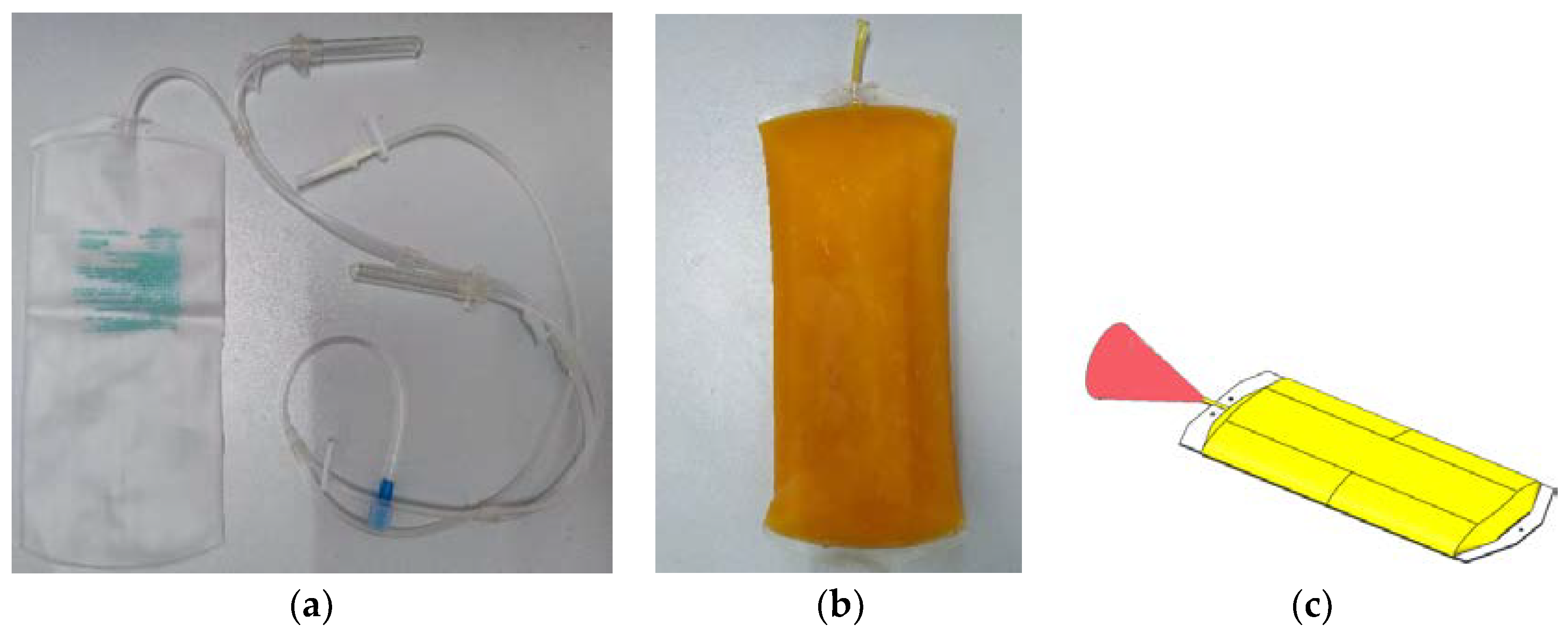
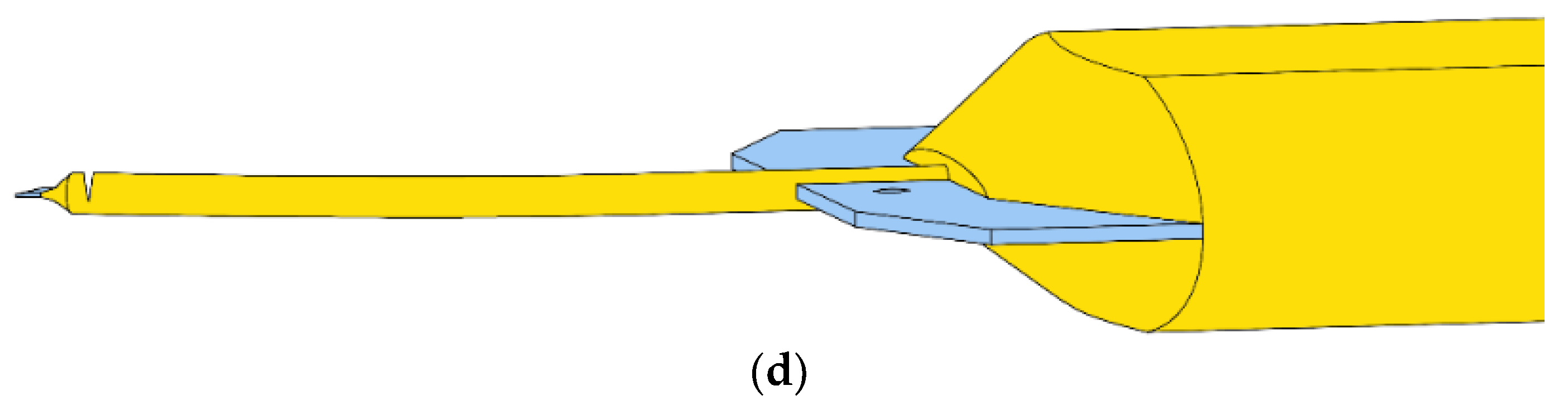
This study aimed to design a system that could accurately identify the exact location of a residual-input tube randomly distributed in a frozen plasma bag and to precisely cut it. Specifically, an unused semi-transparent plasma bag made of polyvinyl chloride material, as shown in Figure 1a. After collection, the input tube was cut and sealed before the first bifurcation point, as shown in Figure 1b. The color of the input tube was light yellow, and after freezing, the residual-input tube exhibited partial flexibility. The residual-input tube was randomly distributed when frozen, as shown in Figure 1c, and the red area indicates the range of the randomly distributed residual-input tube. The residual-input tube was distributed around the endpoint of the plasma bag and formed a cone-shaped range. The cutting requirement of the system was to cut more than half of the radial end of the input tube, while the end was still attached to the input tube, as shown in Figure 1d, making subsequent operations easier and reducing subsequent design difficulties.
2.2. Experimental Principles
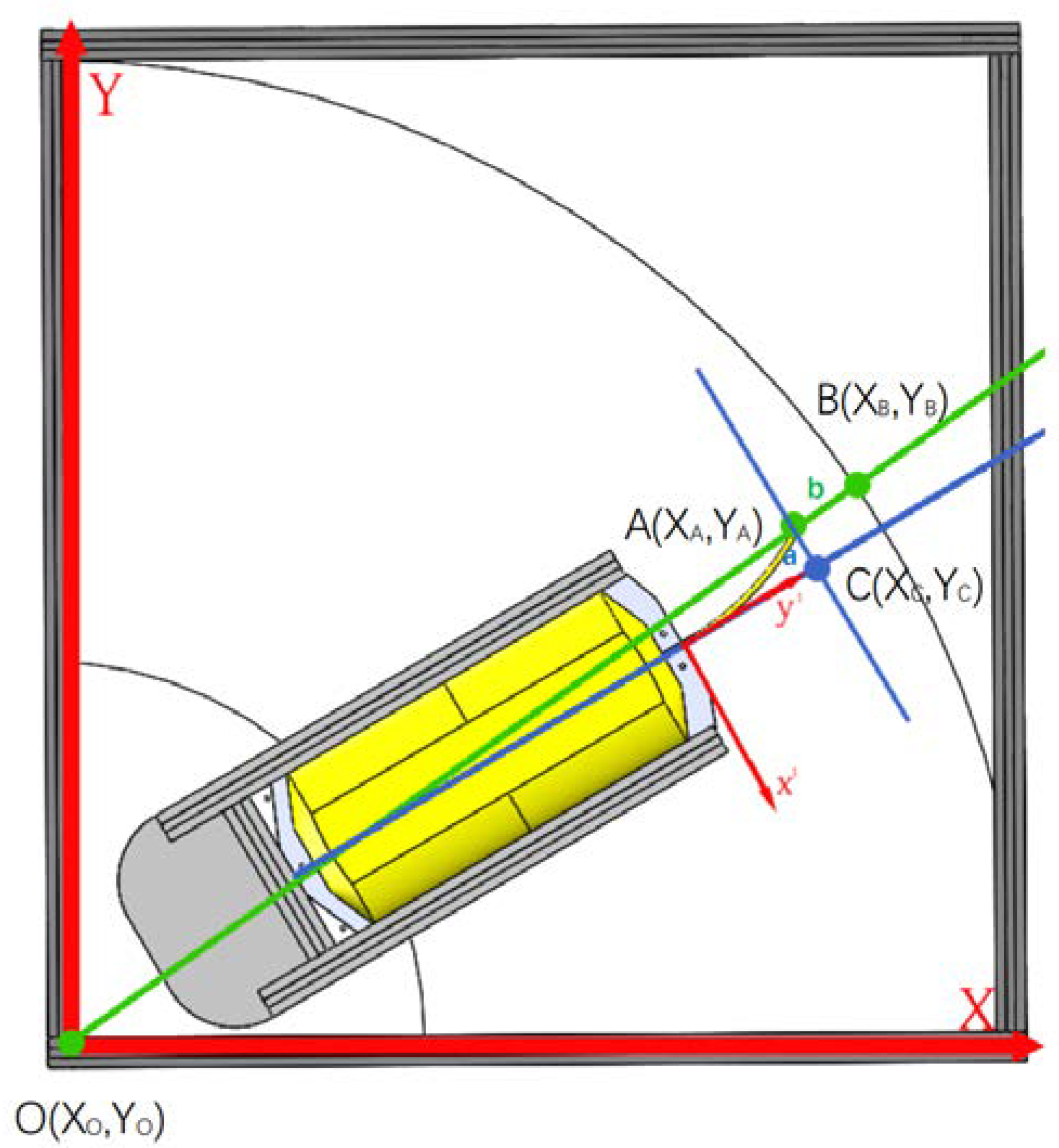
After obtaining the coordinates of the plasma bag for the input tube end and the circle center fitted on the rotating platform , the system calculated a straight-line function to draw a continuous extension line. Subsequently, we used a loop function to determine the intersection point between the extension line and the disc edge. This intersection point determined the distance between the plasma bag and the disc. Figure 2 illustrates the measurement principle.
The Euclidean distance between the end position of the plasma-bag input tube and the coordinates of the intersection point was calculated using the formula .
As the detected corner points exhibited a certain degree of symmetry, we calculated the midpoint coordinates of the outermost pair of corner points. Subsequently, we iteratively calculated the midpoint coordinates of the corner points, with eight iterations in total. Finally, we drew a line connecting the two midpoint coordinates to approximate the central line. We then drew a line perpendicular to the central line through point A and determined the intersection point as point C. The distance between points A and C represents the distance from the input-tube endpoint to the central line. Although this method may have a relatively large measurement error, it is sufficient if cutting with longer blades, meeting the required cutting precision.
In addition, the system faced recognition errors due to the stainless-steel material of the background, which had a color similar to that of the plasma bag and produced reflection under the light source. To address this issue, we continuously sampled the residual-input tube when it was in the camera’s field of view and took average of the collected data to obtain the final cutting position. After being frozen, the residual-input tube of a blood plasma bag was randomly dispersed. In general, it moved freely with the bag, but in some instances, the end of the input tube came into contact with the supporting surface, resulting in new deformation when the bag was moved. If we used the common approach of sampling with the camera and then averaging all of the results to eliminate camera errors, we could see a significant deviation in the final cutting point from the end in such cases.
When the input tube came into frictional contact with the supporting surface, it underwent deformation in three stages. The first stage was the pre-deformation of the input tube before the plasma bag rotated. The second stage was the deformation that occurred when the plasma bag moved and the input tube experienced some deformation due to friction with the surface. The third stage was when the input tube, affected by the force of friction, moved uniformly with the plasma bag until it reached a stable state. Therefore, it was necessary to obtain the positional information of the input tube after the third stage of deformation in the system and to take the average to obtain a more accurate position of the end of the input tube.
As the residual-input tube was in a state of ice-water mixture and had flexible characteristics, soft body dynamics analysis was required [15].
Before performing soft body dynamics analysis, we needed to establish the global and relative coordinate systems. The center of the supporting plate was obtained by segmenting the background in the images and fitting the circular contour. We then used the supporting plate surface as the origin plane for the global coordinate system and the center of the supporting plate as the origin. To establish the relative coordinate system, we used the plasma bag centerline as the y1-axis; then, we translated the previously calculated line AC to the contour corner mutation point, using this translated line as the x1-axis, and set the supporting plane as the origin plane to obtain the relative coordinate system . The established coordinate system is shown in Figure 2.
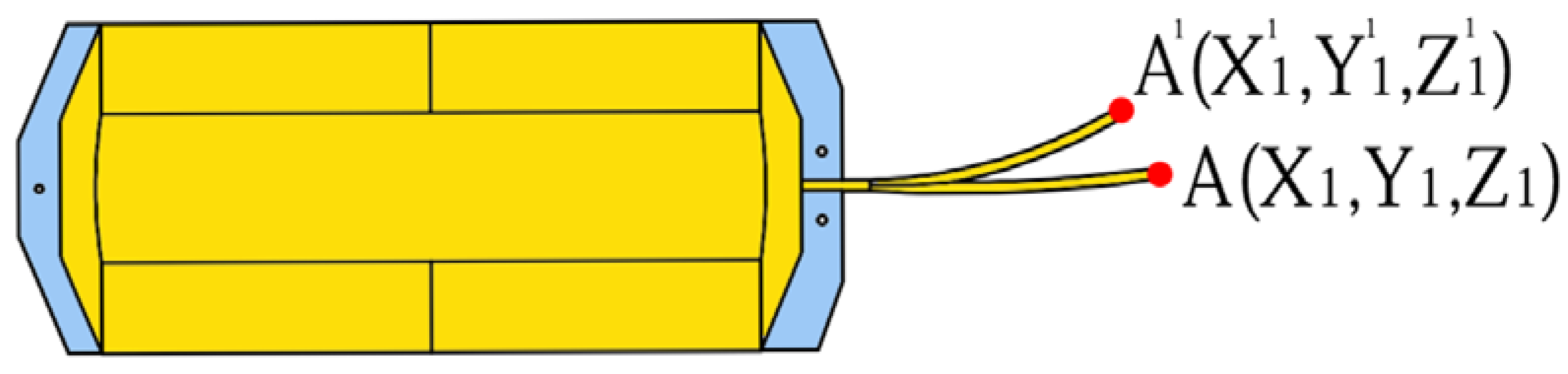
After the coordinate system was established, we used the floating coordinate method to design and analyze it. The endpoint position of the end input tube was point A, and its position in the global coordinate system was calculated using Equation (1), where D is the direction cosine matrix of the relative coordinate system with respect to the global coordinate system; is the position of the input tube endpoint A in the relative coordinate system before deformation; A1 is the position of the deformed input tube endpoint in the relative coordinate system, as shown in Figure 3; is the deformation displacement of the input tube; and R is the position of point A when the input tube is undeformed in the global coordinate system. We then differentiated Equation (1) to obtain the motion velocity of point A, as shown in Equation (3), and differentiated Equation (3) again to obtain the motion acceleration of point A, as shown in Equation (4). The velocity of the plasma bag movement was known, and the time required for the residual-input tube to move without relative displacement was obtained using Equation (5). Once the time ‘t’ was determined, the system calculated the average of the images captured after time ‘t’ to obtain more accurate positional information.
After the system obtained the initial residual-input tube endpoint information, the lead screw slide moved accordingly. When the averaged data were finally obtained, the lead screw slide moved to the calculated position and waited for the residual-input tube endpoint to reach that point before initiating the cutting process.
To calculate the waiting time required for the cutting blade, we determined the angle between line segments OA and OC. The radius of the plasma bag tray, which is known to be 650 mm, was used to calculate the additional rotation angle α needed by the bottom motor, as shown in Equation (6). The bottom stepper motor rotated at a constant speed, and the number of steps required for the additional rotation angle was used to calculate the motor’s forward steps. The step count of the stepper motor was set to n/360°, and the additional rotation steps were determined using Equation (7). The system counted the pulse steps of the stepper motor, and when the required step count was reached, the electromagnet was activated to initiate the cutting process.
3. Experimental Methods and Results
3.1. Experimental Setup
3.1.1. Structural Components of the System Unit
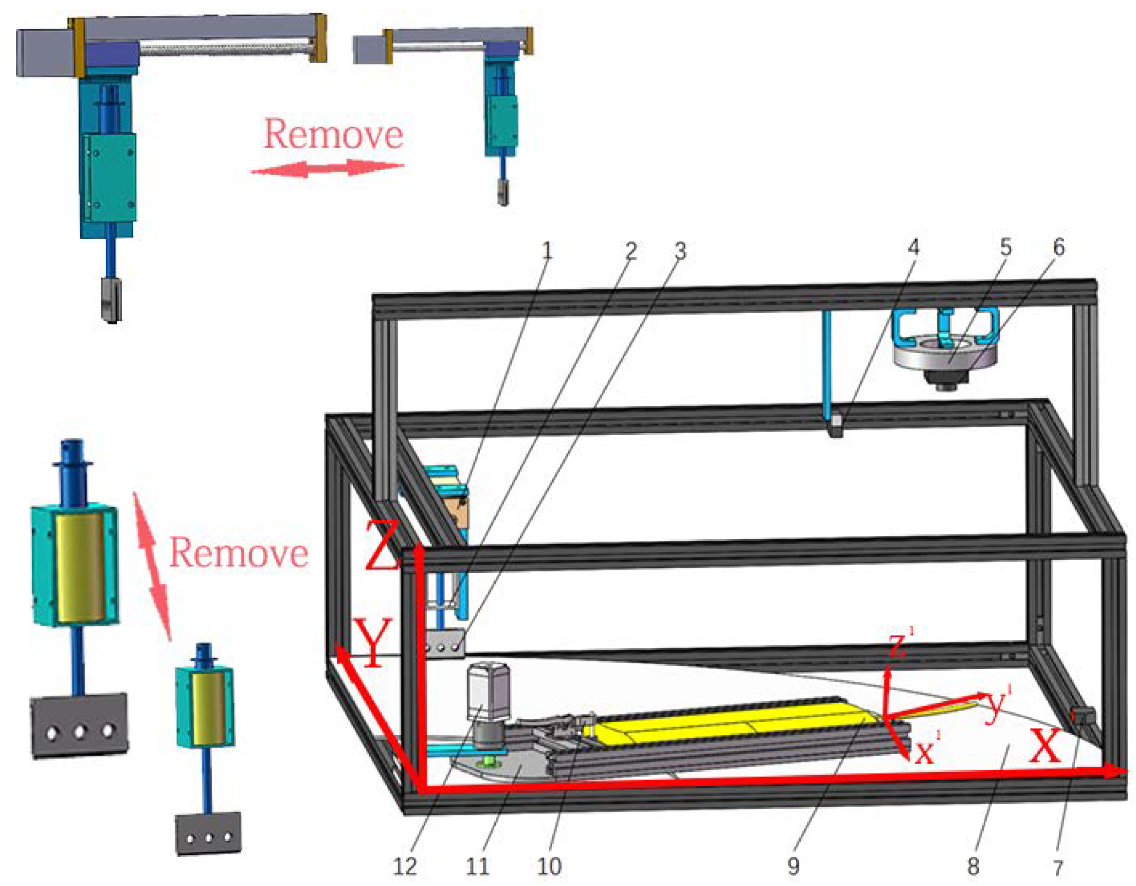
The residual-input tube-cutting system for plasma bags is a simplified version of the plasma-bag cutting machine that focuses on the cutting function of the input tube. The plasma-bag cutting machine consists of input, cutting, and output functions, while the plasma-bag tray is reciprocated on the bottom disk. This system only retains the function of cutting the input tube to facilitate research. The system is composed of a plasma-bag rotating device, a bottom support plate, an image-acquisition device, a screw-slide table, a cutting component, and a device control system, as shown in Figure 4.
The plasma bag was placed on a tray with a clamping mechanism at the top to secure its bottom edge, while baffles on both sides prevented any relative movement between the bag and tray during rotation. The plasma bag rotation device was driven by a reducer stepper motor with a maximum speed of 174 r/min. A side optical sensor was mounted to detect whether the input tube was in contact with the bottom surface. The image acquisition device, comprised of a photoelectric sensor, a light source, and a camera, was positioned above the rotation path of the bag. The camera lens was positioned 300 mm above the bottom support plate and had a resolution of 640 480. It captured 120 frames per second. The cutting device was composed of a lead screw slide, an electromagnetic actuator, and a cutting blade. The lead screw slide table had a 50 mm stroke and was powered by a separate stepper motor. It was mounted parallel to the edge of the lower support plate. The electromagnetic actuator was fixed to the lead screw slide, and the cutting blade was attached to the push rod’s end. The cutting device moved along the Y-axis of the global coordinate system, as shown in Figure 4. Using the distance read by the vision system, the cutting device moved to the corresponding position on the Y axis and waited for the end of the remaining input tube. Once the end arrived, the electromagnetic switch was turned on, causing the cutting blade to move downwards along the Z axis of the global coordinate system and cut the input tube. The maximum distance that the electromagnetic switch could travel was 1 mm from the support surface, which satisfied the design requirements for cutting the end of the input tube. The electromagnetic switch had a travel distance of less than 10 mm, allowing for fast response times.
3.1.2. Device Control System
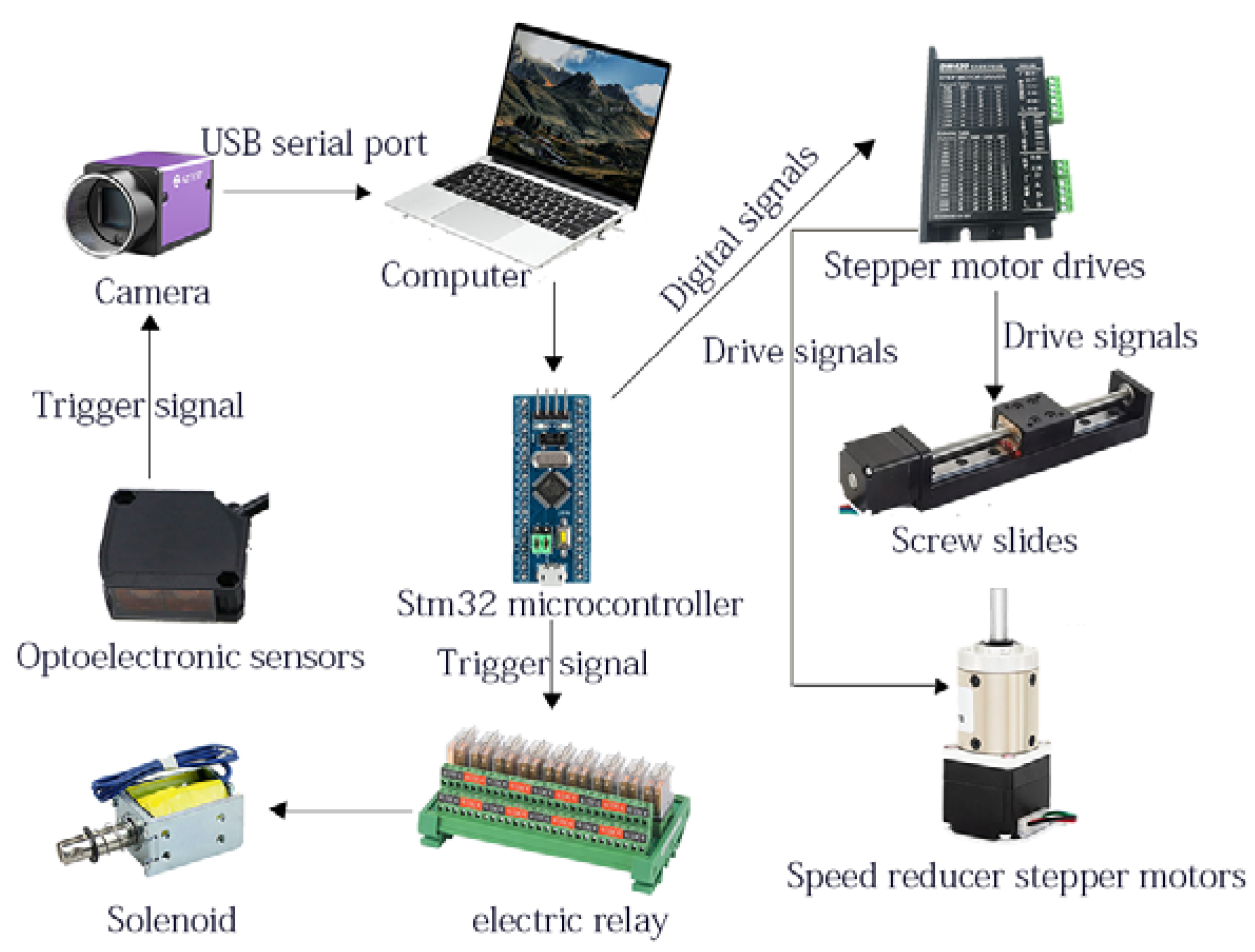
The control system of the residual-input tube-cutting system for plasma bags comprised a computer, camera, Stm32 micro controller, photoelectric sensor, screw slide, stepper motor driver, reducer stepper motor, electromagnet, and serial module, among other components. Its major function was to detect the end position of the input tube by capturing the image of the plasma-bag input tube and controlling the feed and reset of the cutting device driven by the screw slide. The reducer stepper motor drove the plasma bag in a reciprocating cycle of work, ultimately energizing the electromagnet to perform the input tube-cutting action. Figure 5 illustrates the control system of the plasma-bag-cutting device.
3.1.3. Device Working Process
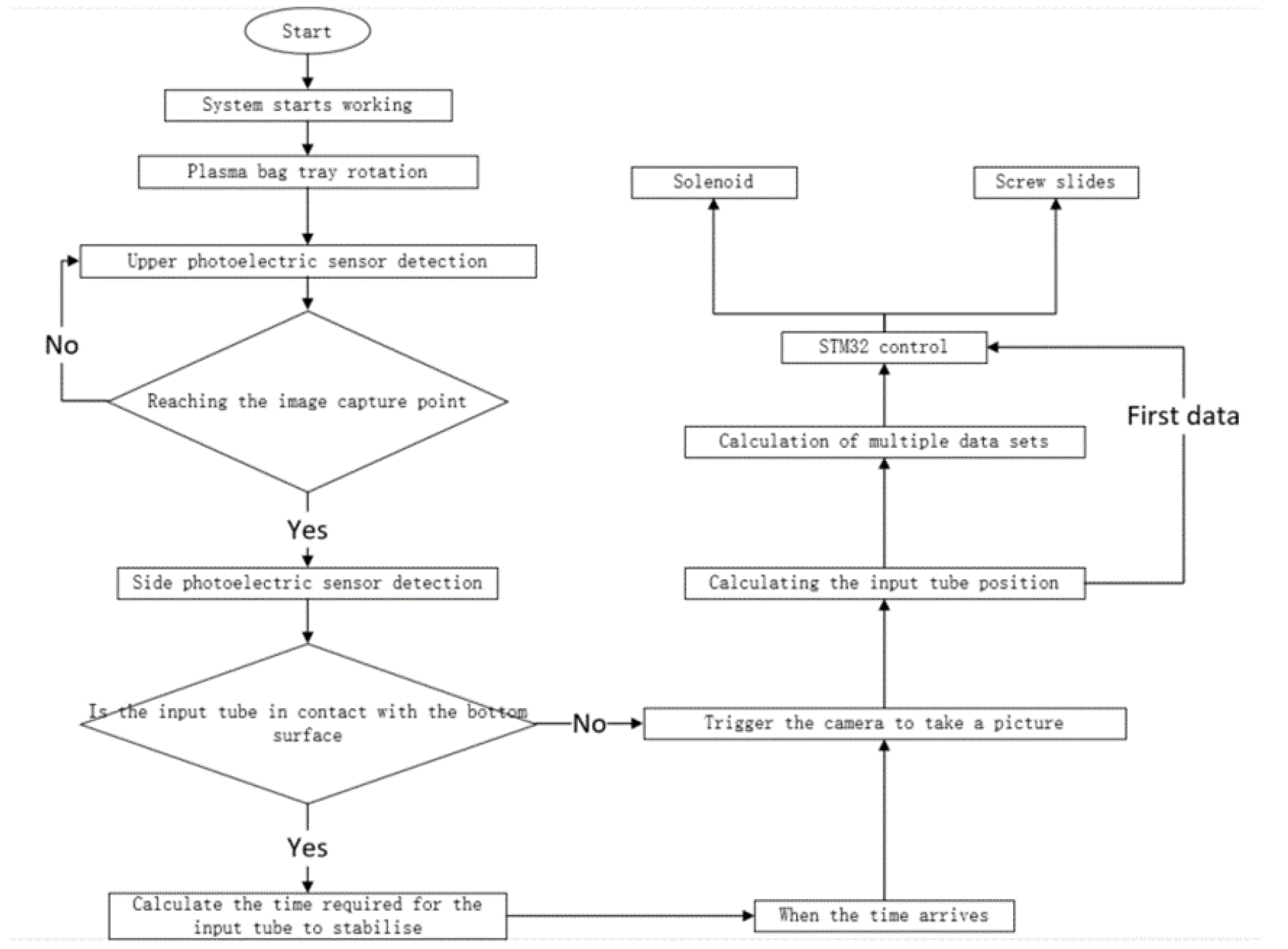
During the operation of the plasma bag’s residual-input tube-cutting system, the bag was positioned on a tray with its input tube facing outward. As the conveying device rotated, the plasma bag passed through an image-acquisition device. A photoelectric sensor on the top triggered the camera to capture images of the plasma bag, while a photoelectric sensor on the side verified the contact between the input tube and the bottom surface. The camera captured 20 frames of images at equal intervals. Upon acquiring the first frame of the image, the image processing program was invoked to compute the position information, which was then communicated to the STM32 via a serial port. The microcontroller governed the movement of the lead screw slide according to the data obtained in the first frame. If the program detected contact between the input tube and the bottom surface, it selected an image sampled at the duration required for the input tube to exhibit no relative displacement, and computed and processed it using the soft body kinematics algorithm. If no contact was detected, the image processing program processed all of the collected images. The averaged processed data were then relayed to the STM32 to control the lead screw slide until it reached the final position. Once the input tube reached the cutting position, the electromagnet energized it to cut it. A flow chart of the system’s operational process is illustrated in Figure 6.
3.2. Experimental Preparation
In practical production, the length of the residual-input tube must be at least as long as the length of a barcode to attach it. During the preparation of the experimental plasma bags, the input tube was cut and sealed after the first node closest to the bag, before affixing the barcode label, within a length range of approximately 45–85 mm.
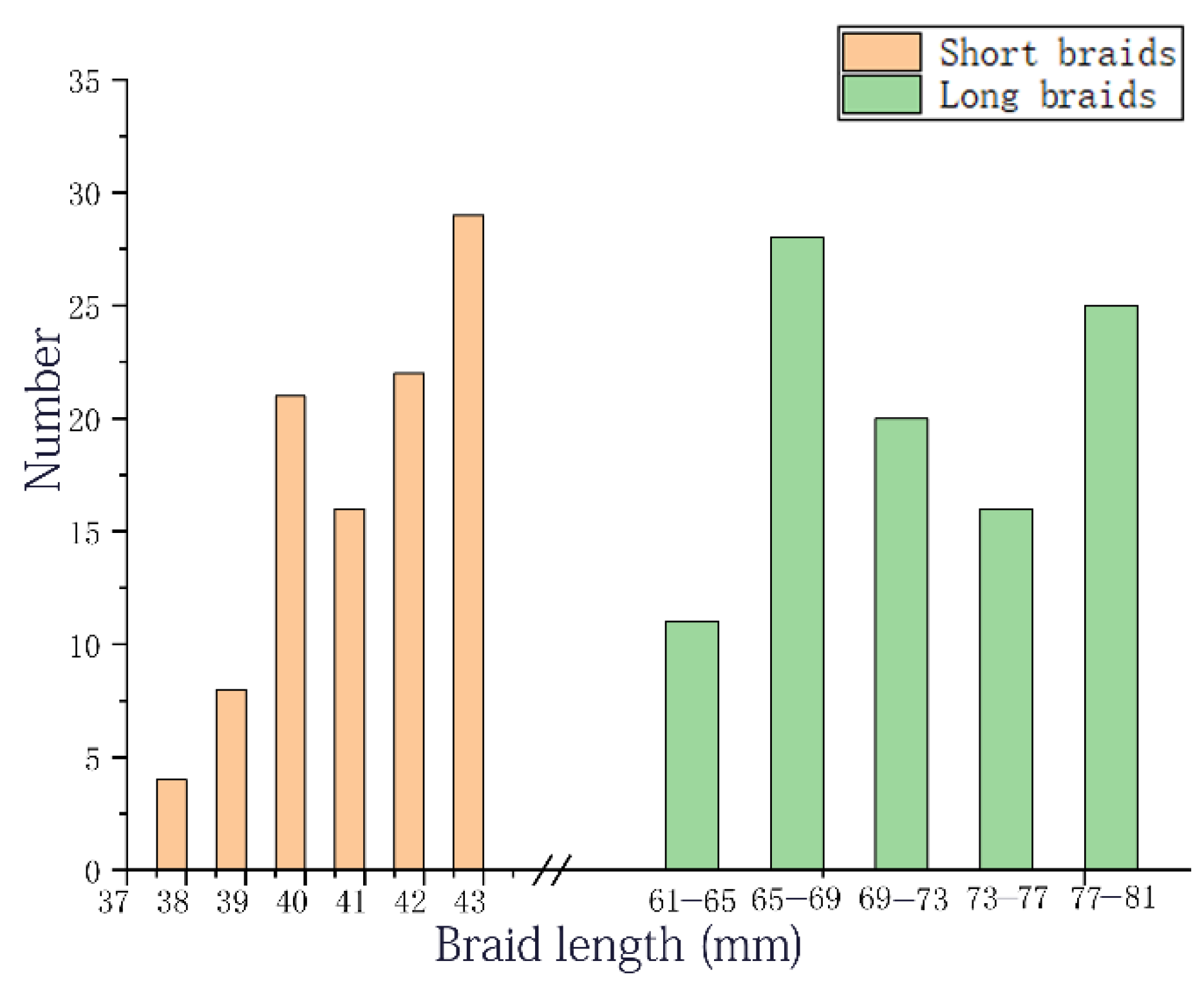
To test whether the system could perform cutting under extreme conditions of the longest and shortest input tube lengths, we conducted other tests. We cut and sealed the input tube at 85 mm and 45 mm for 10 bags of plasma, which were then randomly placed in a freezer. The straight-line distance from the end of the input tube to the edge of the plasma bag was measured, and 200 data points were collected and statistically analyzed, as shown in Figure 7. The results indicated that the maximum radial distance of the input tube was 81 mm, while the minimum was 38 mm, with a difference of 43 mm between the two. The lead screw slide used by the system met the requirements.
3.3. Image Processing Process
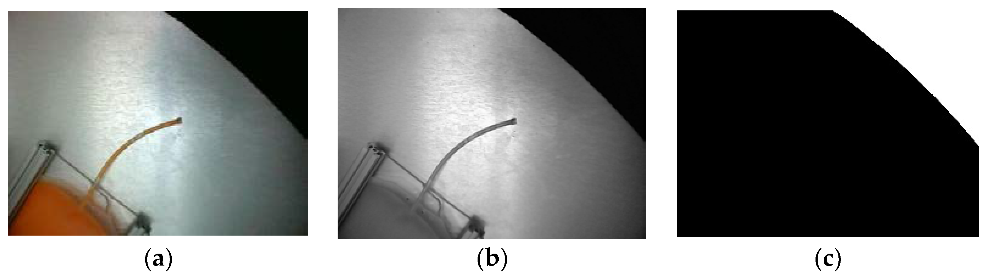
In this study, we utilized an image processing approach to measure the position of the distal end of the input tube and calculate the cutting position. When the plasma bag arrived at the image acquisition point, the camera captured an image of the bag, which was then saved to a designated folder. The original picture of the plasma bag, as shown in Figure 8a, was preprocessed to improve the speed of the algorithm.
In this study, we conducted grayscale conversion [16,17] on the captured image, and the resulting image is depicted in Figure 8b. The grayscale image was obtained using the formula . Then, we converted the grayscale image to a binary image using a threshold value of , which was determined based on preliminary experiments. The binary image, shown in Figure 8c, was processed to extract the disk’s edge, which was identified as the black boundary. As the acquired image only covered a small part of the disk, we performed circular fitting on the continuous edge using the least-squares method to estimate the circle’s parameters and determine the disk’s center coordinates in the camera coordinate system.
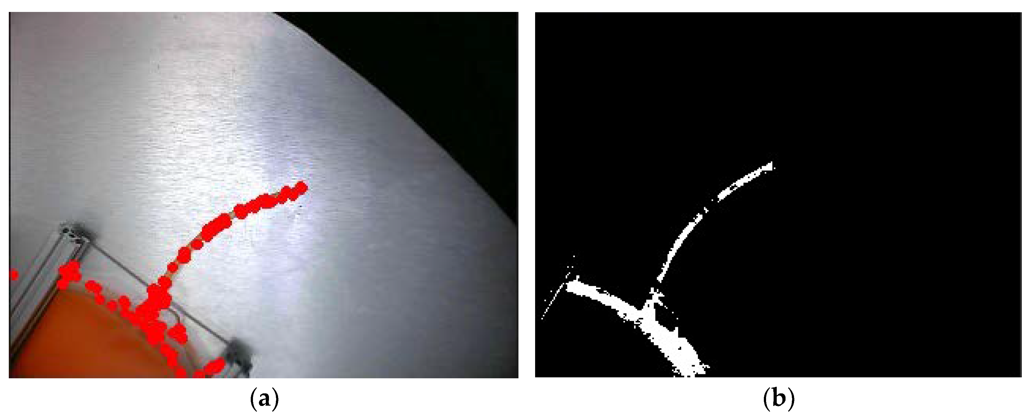
The input tube of the plasma bag was recognized by first extracting the bag’s color [18,19,20,21] and constructing a corresponding color image. Then, the Euclidean distance between each pixel in the camera-captured image and each pixel in the constructed-color image was calculated. Following optimization and experimentation, a recognition distance of Dos = 25 was selected for the input tube’s color identification. Any pixel in the sampled photo whose distance to the similar pixel in the image was less than Dos satisfied the recognition distance criterion. A mask image was then constructed based on the corresponding pixel points in the sampled photo, with the input tube’s position marked as 255 and all other unsatisfied pixel values set to 0, resulting in the mask image of the input tube’s location, as shown in Figure 9a.
We performed corner-point detection [22,23,24,25] on the mask image to identify pixels with a high rate of change. After calibration, we selected a threshold value of 100 and marked the corner points with circles, and plotted them on the graph. We applied a cyclic function to filter out low-confidence corner points and identify reliable ones. Thus, we found the endpoint of the plasma input tube among all corner points. In addition, the image was input in a circular way. If the pixel value was higher than the threshold value, then the point was a corner point and plotted on the graph; if it was lower than the threshold value, then the point could be discarded directly. Utilizing the identified corner points, we calculated the distance from the previously obtained disc outline to pinpoint the end of the input tube. The endpoint was determined as the corner point that was closest to the disc. Figure 9b shows the identified corner points.
In this study, after obtaining the pixel distance, we converted it to linear distance [26,27]. The triangulation method was employed to calibrate the actual distance as the scaling ratios for the horizontal and vertical directions in the image were not the same, which required calibration of two sets of points to solve the equation. The following two equations were used:
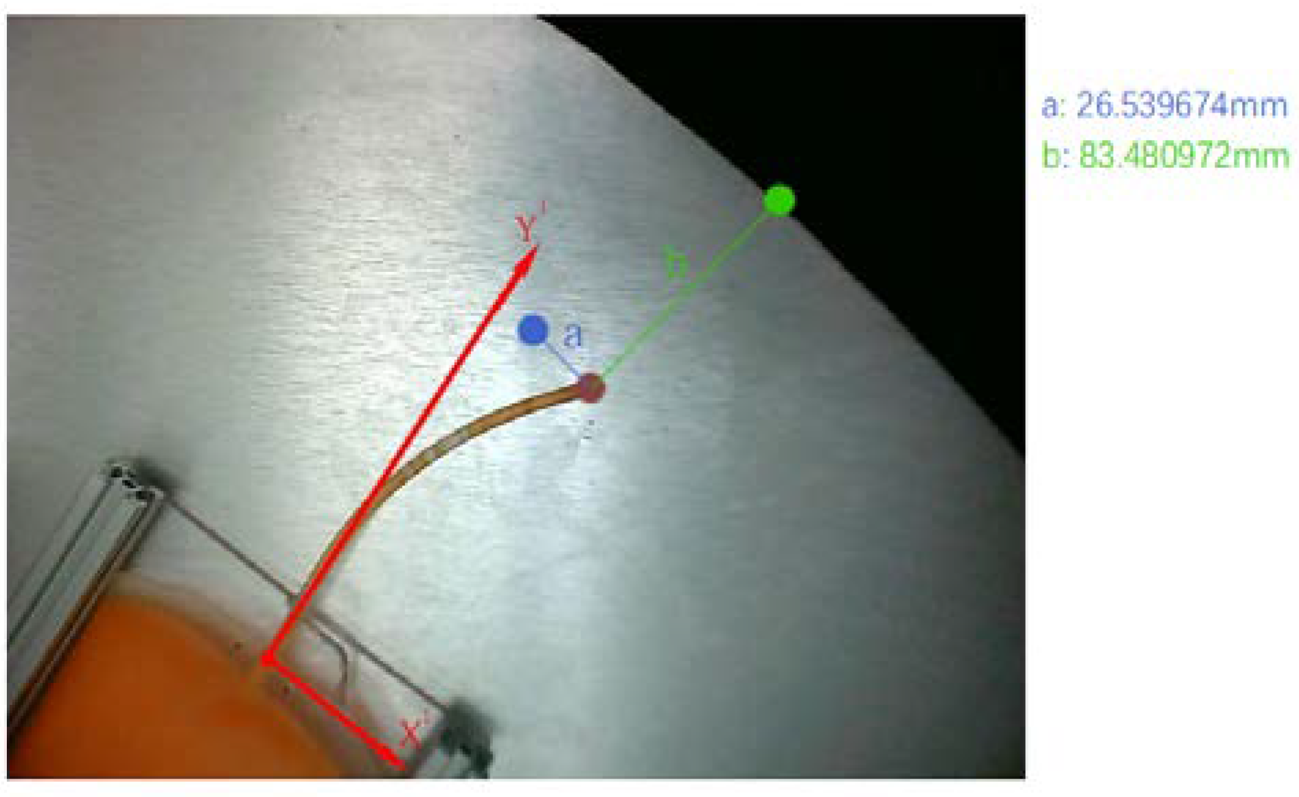
The distance of the residual-input tube in practice was derived from the values obtained for and and the previously obtained pixel distances. The ranging plot is shown in Figure 10, and some of the experimental ranging errors are presented in Table 1. The image processing time was about 60 ms, and the camera field of view was about one-half of the disc so as to ensure that the image was fully processed and cutting was completed. The rotation time of the tray was also controlled to be within 10 s per rotation.
According to Table 1, there was some error in the distance in the X and Y directions. In the X direction, the error was larger, and the measured values had positive and negative values, which was within the expected error. In the Y direction, the error was smaller and met the requirements for practical use.
To minimize identification errors, we conducted image sampling and recognition of the plasma bag every 50 ms using the camera, followed by averaging the obtained parameters for more precise values, which were subsequently relayed to the lead screw slide. To evaluate the efficacy of this approach for enhancing accuracy, we initially conducted sampling upon detection of the plasma bag by the upper photoelectric sensor, after which we intermittently halted the tray rotation every 0.2 s for camera sampling and manual measurement of the input tube position, so as to determine the error magnitude. We repeated the sampling and halting process five times and compared the first sampled value with the mean of six samples, thereby assessing the degree to which the accuracy had been improved.
Table 2 shows the positional data of the same plasma bag measured multiple times. The table reveals that during the same experiment, the first sampling may have resulted in relatively large a-directional errors due to the plasma bag not being fully captured by the camera. Therefore, we excluded the first sampling data and averaged the remaining data when calculating the mean error in the a-direction. The b-directional error fluctuated less during each sampling, so we averaged the b-values of the six samplings. The data in the table show that the error was effectively reduced in most cases. However, when the error was already low during the first sampling, there may have been reverse optimization results. Therefore, after weighing the pros and cons of the options, we ultimately chose the mean error method. In actual production processes, a 100% cutting completion rate should be achieved despite larger cutting errors. As the b-directional error was consistently positive, the screw slide only needed to be cut at the averaged b-value to ensure complete cutting.
3.4. Control Accuracy
In the system, errors appeared superimposed. To achieve the system’s functionality accurately, both the accuracy of the visual inspection and that of the individual actuators needed to be met [28,29,30,31]. Consequently, the accuracy of the individual actuators was verified.
- (1)
- Verification of the accuracy of the reducer stepper motor control.
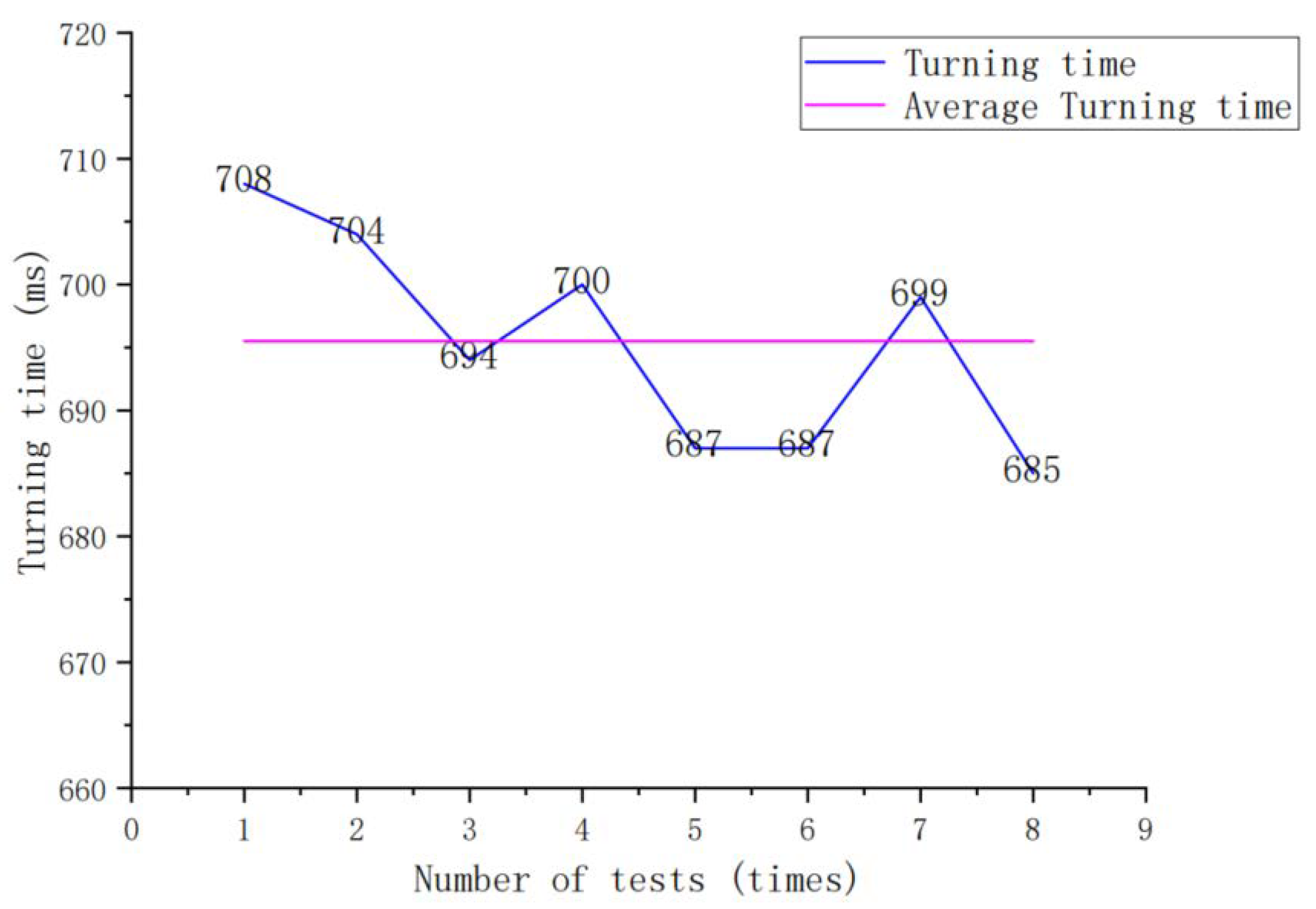
The accuracy of the reducer stepper motor was crucial for the camera to achieve optimal functionality in terms of capturing sufficient samples and achieving accurate cutting. The reducer stepper motor was equipped with a code plate on the output shaft, enabling the detection of the angle of rotation and closed-loop control of the motor angle. However, speed requirements also needed to be met. Thus, we conducted tests to determine the time required to rotate the same angle in practice.
Two photoelectric sensors were installed at a specific distance apart in the rotation path of the plasma bag tray. They were triggered in sequence as the plasma bag tray rotated, and the timer in the STM32 recorded the duration between the sensor triggers.
The experimental results presented in Figure 11 demonstrate that the average rotation time was 695.5 ms. The graph also shows that the angle fluctuation range of the gearbox stepper motor was small and stable.
- (2)
- Verification of the control accuracy of the screw slide
Efficiency was one of the important indicators in the system design requirements, and as such, the rotation platform must move quickly. However, due to the significant speed loss associated with the screw structure’s conversion of rotary motion to linear motion, it w essential to strike a balance between precise control of the screw slide and increased speed. The more subdivisions the stepping motor had, the more precise it became, but its rotation speed decreased. The table below displays the step angle setting and the time required for the screw slide to move 50 mm. Based on the pitch of the screw rod being 6 mm, we calculated the required number of motor steps and used the proportion of error between the actual and calculated pulse counts to determine the appropriate frequency division pulse.
Figure 12 shows that the stepper motor experienced a significant loss of step at a frequency division pulse of 400. However, after removing this data, the remaining data exhibited minor fluctuations and good stability. The system required the slide to travel a maximum distance of 50 mm, had a camera first shot time of 0.3 s and a complete pallet rotation time of 2.5 s, allowing ample time for system movement. Additionally, the error ratio satisfied the selection criteria, and thus the pulse 800 frequency division was selected.
3.5. Experimental Effects
In order to validate the performance of the residual-input end-cutting system for plasma bags, we conducted experiments simulating actual plasma-bag conditions. We placed the blood bags in random positions during the freezing process, and after the freezing was completed, we conducted experiments on the experimental platform. During the experiment, we fixed the front end of the plasma bag and randomly placed the input tube, recorded whether the system could cut out the required incision completely, and measured the distance between the cutting incision and the end of the input tube. Some of the experimental data are shown in Table 3. In addition, we also conducted experiments on the cutting effect when the input tube was in contact with the bottom surface. The experimental data are shown in Table 4. The experimental setup for the residual-input end-cutting system for plasma bags is shown in Figure 13. According to the data in the table, the error rate of the incision cut by the system was within 10%, which met the process requirements and achieved the design goal. Additionally, the use of the flexible body kinematics algorithm significantly improved the cutting accuracy when the residual-input tube of the plasma bag was in contact with the bottom surface compared with when no additional algorithm was used.
4. Discussion
The paper presents a system that performs detection and execution during its motion process through the collaboration of detection algorithms and driving actuators. The system’s detection accuracy, execution accuracy, and overall accuracy are all verified. After repeated testing, the system had some random errors in detection, which were reduced by continuously collecting images and optimizing the average values. Regarding drive execution, the system planned the timing to improve the efficiency of the screw slide movement and achieved a balance between efficiency and precision.
In this paper, we first observed and analyzed the distribution of residual-input tubes in the plasma-bag distribution feature and classified it into two types: residual tube ends rotate normally with the plasma bag and residual tube ends rub against the supporting surface during rotation. In the design of the plasma bag cutting machine, it needs to recognize and cut the residual-input tube ends during the rotation process. When the residual-input tube end rubs against the supporting surface, it produces displacement relative to the plasma bag for some time. To solve this issue, the paper established a coordinate system model based on data collected from multiple images and introduced a soft-body dynamics algorithm to calculate the time required to complete the deformation. After the deformation was completed, images were collected and detected, and the average value was optimized. The cutting component then moved to the calculated value and waited for the residual-input tube to arrive, finally completing the end cutting and obtaining a more accurate final result.
5. Conclusions
This study developed a machine-vision-based system for cutting the residual-input tubes of blood-plasma bags. The system included a detection unit and an execution unit. To ensure its precision would meet industrial requirements, we improved the cutting accuracy by reducing identification and driving errors, separately. For identification errors, we used multiple data samples and average the values to reduce end-position identification errors. To address the input tube’s contact with the bottom, we applied a soft-body kinematics algorithm to calculate the input tube’s required time for stabilization and processed camera sampling and multiple data averaging. We verified the effectiveness of this method by setting up a control group, which improved the system’s cutting precision. Regarding driving errors, we performed driving tests on each actuator and verified their stability and accuracy. The experimental results demonstrated that the system could complete the entire process within 2.5 s per bag, with a relative error of less than 10% for the knife distance, and excellent cutting performance of the input tube’s knife mouth, which meets the industrial requirements for subsequent blood extraction. This system solves one of the technical challenges in automatic equipment for breaking blood-plasma bags.
Author Contributions
Conceptualization, J.Y. and L.Z.; methodology, J.Y.; software, S.L.; validation, J.Y., P.W. and J.C.; resources, L.Z.; data curation, S.L.; writing—original draft preparation, J.Y.; writing—review and editing, J.Y., P.W. and J.C.; project administration, L.Z.; funding acquisition, L.Z. All authors have read and agreed to the published version of the manuscript.
Funding
This research received no external funding.
Institutional Review Board Statement
Not applicable.
Informed Consent Statement
Not applicable.
Data Availability Statement
Not applicable.
Conflicts of Interest
The authors declare no conflict of interest.
References
- Wang, P.; Zhao, H.; Ren, G. Development and Application of Standard Device for Calibrating Steel Measuring Tape Based on Machine Vision. Appl. Sci. 2022, 12, 7262. [Google Scholar] [CrossRef]
- Lee, W.C.; Huang, K.C. Measuring the Positions of the Solder Pins of Electrical Connectors from the Side. Appl. Sci. 2022, 12, 8772. [Google Scholar] [CrossRef]
- Furferi, R.; Servi, M. A Machine Vision-Based Algorithm for Color Classification of Recycled Wool Fabrics. Appl. Sci. 2023, 13, 2464. [Google Scholar] [CrossRef]
- Wang, W.C.; Chen, S.L.; Chen, L.B.; Chang, W.J. A Machine Vision Based Automatic Optical Inspection System for Measuring Drilling Quality of Printed Circuit Boards. IEEE Access 2017, 5, 10817–10833. [Google Scholar] [CrossRef]
- Comari, S.; Carricato, M. Vision-Based Robotic Grasping of Reels for Automatic Packaging Machines. Appl. Sci. 2022, 12, 7835. [Google Scholar] [CrossRef]
- Chao, M.; Kai, C.; Zhiwei, Z. Research on Tobacco Foreign Body Detection Device Based on Machine Vision. Trans. Inst. Meas. Control 2020, 42, 2857–2871. [Google Scholar] [CrossRef]
- Lei, T.; Wang, W.; Rong, Y.; Xiong, P.; Huang, Y. Cross-Lines Laser Aided Machine Vision in Tube-to-Tubesheet Welding for Welding Height Control. Opt. Laser Technol. 2020, 121, 105796. [Google Scholar] [CrossRef]
- He, W.; Zhang, A.; Wang, P. Weld Cross-Section Profile Fitting and Geometric Dimension Measurement Method Based on Machine Vision. Appl. Sci. 2023, 13, 4455. [Google Scholar] [CrossRef]
- Li, R.; Zhao, S.; Yang, B. Research on the Application Status of Machine Vision Technology in Furniture Manufacturing Process. Appl. Sci. 2023, 13, 2434. [Google Scholar] [CrossRef]
- Yang, W.; Zhang, Y.; Dong, Y.; Xu, D.; Pan, T. Development of Machine Vision System for Off-Line Inspection of Fine Defects on Glass Screen Surface. IEEE Trans. Instrum. Meas. 2022, 71, 5016008. [Google Scholar] [CrossRef]
- Wang, F.; Xie, B.; Lü, E.; Zeng, Z.; Mei, S.; Ma, C.; Guo, J. Design of a Moisture Content Detection System for Yinghong No. 9 Tea Leaves Based on Machine Vision. Appl. Sci. 2023, 13, 1806. [Google Scholar] [CrossRef]
- Jia, X.; Ma, P.; Tarwa, K.; Wang, Q. Machine Vision-Based Colorimetric Sensor Systems for Food Applications. J. Agric. Food Res. 2023, 11, 100503. [Google Scholar] [CrossRef]
- Brambilla, P.; Conese, C.; Fabris, D.M.; Chiariotti, P.; Tarabini, M. Algorithms for Vision-Based Quality Control of Circularly Symmetric Components. Sensors 2023, 23, 2539. [Google Scholar] [CrossRef]
- Huynh, T.; Tran, M.T.; Lee, D.H.; Chakir, S.; Kim, Y.B. A Study on Vision-Based Backstepping Control for a Target Tracking System. Actuators 2021, 10, 105. [Google Scholar] [CrossRef]
- Lan, P.; Shabana, A.A. Rational Finite Elements and Flexible Body Dynamics. J. Vib. Acoust. 2010, 132, 041007. [Google Scholar] [CrossRef]
- Ma, F.; Jing, X.Y.; Zhu, X.; Tang, Z.; Peng, Z. True-Color and Grayscale Video Person Re-Identification. IEEE Trans. Inf. Secur. 2020, 15, 115–129. [Google Scholar] [CrossRef]
- Hagara, M.; Stojanović, R.; Bagala, T.; Kubinec, P.; Ondráček, O. Grayscale Image Formats for Edge Detection and for Its FPGA Implementation. Microprocess. Microsyst. 2020, 75, 103056. [Google Scholar] [CrossRef]
- Kartika, D.S.Y.; Herumurti, D.; Rahmat, B.; Yuniarti, A.; Maulana, H.; Anggraeny, F.T. Combining of Extraction Butterfly Image Using Color, Texture and Form Features. In Proceedings of the 2020 6th Information Technology International Seminar (ITIS 2020), Surabaya, Indonesia, 14–16 October 2020; pp. 98–102. [Google Scholar]
- Latif, A.; Rasheed, A.; Sajid, U.; Ahmed, J.; Ali, N.; Ratyal, N.I.; Zafar, B.; Dar, S.H.; Sajid, M.; Khalil, T. Content-Based Image Retrieval and Feature Extraction: A Comprehensive Review. Math. Probl. Eng. 2019, 2019, 21. [Google Scholar] [CrossRef]
- Mutlag, W.K.; Ali, S.K.; Aydam, Z.M.; Taher, B.H. Feature Extraction Methods: A Review. In Journal of Physics: Conference Series; IOP Publishing Ltd.: Bristol, UK, 2020; Volume 1591. [Google Scholar]
- Gao, J.; Thung, J.S.; Wei, S.; Pavlů, D.; Chee, C.S.; Ramasamy, Y.; Mohd Ali, A.S.B.; Mat Yatim, R.B. Absolute Reliability and Concurrent Validity of the Modified Goniometric Platform for Measuring Trunk Rotation in the Sitting Position. Appl. Sci. 2022, 12, 8891. [Google Scholar] [CrossRef]
- Xiong, W.; Tian, W.; Yang, Z.; Niu, X.; Nie, X. Improved FAST Corner-detection Method. J. Eng. 2019, 2019, 5493–5497. [Google Scholar] [CrossRef]
- Cuevas, E.; Rodríguez, A.; Alejo-Reyes, A.; Del-Valle-Soto, C.; Cuevas, E.; Rodríguez, A.; Alejo-Reyes, A.; Del-Valle-Soto, C. Corner Detection Algorithm Based on Cellular Neural Networks (CNN) and Differential Evolution (DE). In Recent Metaheuristic Computation Schemes in Engineering; Springer International Publishing: Cham, Switzerland, 2021; pp. 125–149. [Google Scholar]
- Bansal, M.; Kumar, M.; Kumar, M.; Kumar, K. An Efficient Technique for Object Recognition Using Shi-Tomasi Corner Detection Algorithm. Soft Comput. 2021, 25, 4423–4432. [Google Scholar] [CrossRef]
- Henila, M.; Chithra, P. Segmentation Using Fuzzy Cluster-Based Thresholding Method for Apple Fruit Sorting. IET Image Process 2020, 14, 4178–4187. [Google Scholar] [CrossRef]
- Hsu, C.-C.; Lu, M.-C.; Wang, W.-Y.; Lu, Y.-Y. Distance Measurement Based on Pixel Variation of CCD Images. ISA Trans. 2009, 48, 389–395. [Google Scholar] [CrossRef] [PubMed]
- Guan, J.; Yang, X.; Ding, L.; Cheng, X.; Lee, V.C.S.; Jin, C. Automated Pixel-Level Pavement Distress Detection Based on Stereo Vision and Deep Learning. Autom Constr. 2021, 129, 103788. [Google Scholar] [CrossRef]
- Kumar, P.R. Position Control of a Stepper Motor Using LabView. In Proceedings of the 2018 3rd IEEE International Conference on Recent Trends in Electronics, Information & Communication Technology (RTEICT), Bangalore, India, 18–19 May 2018; pp. 1551–1554. [Google Scholar]
- Chuyen, T.D.; Nguyen, V.H.; Dao, P.N.; Tuan, N.A.; Van Toan, N. Sliding Mode Control Strategy Based Lead Screw Control Design in Electromechanical Tracking Drive System. Int. J. Power Electron. Drive Syst. 2022, 13, 150–158. [Google Scholar] [CrossRef]
- Boldea, I.; Nasar, S.A. Electric Drives; CRC Press: Boca Raton, FL, USA, 2016. [Google Scholar]
- Qi, F.-Q.; Jing, X.-D.; Zhao, S.-Q. Design of Stepping Motor Control System Based on AT89C51 Microcontroller. Procedia Eng. 2011, 15, 2276–2280. [Google Scholar]
Figure 1.
Various types of plasma bags: (a) unused plasma bags, (b) frozen plasma bags, (c) input-tube random-distribution chart, and (d) input-tube cutting effect.
Figure 1.
Various types of plasma bags: (a) unused plasma bags, (b) frozen plasma bags, (c) input-tube random-distribution chart, and (d) input-tube cutting effect.


Figure 2.
Distance measuring schematic.

Figure 3.
Diagram of the plasma-bag input-tube movement.

Figure 4.
Overall system architecture diagram. (1) screw slide, (2) solenoid, (3) guillotine, (4) top photoelectric sensor, (5) light source, (6) camera, (7) side photoelectric sensor, (8) bottom disc, (9) plasma bag, (10) clamping mechanism, (11) plasma bag tray, and (12) reducer stepper motor.
Figure 4.
Overall system architecture diagram. (1) screw slide, (2) solenoid, (3) guillotine, (4) top photoelectric sensor, (5) light source, (6) camera, (7) side photoelectric sensor, (8) bottom disc, (9) plasma bag, (10) clamping mechanism, (11) plasma bag tray, and (12) reducer stepper motor.

Figure 5.
Control system composition.

Figure 6.
System flow chart.

Figure 7.
Plot of the difference in distance from the end of the braid to the edge of the plasma bag.
Figure 7.
Plot of the difference in distance from the end of the braid to the edge of the plasma bag.

Figure 8.
Disc image processing process: (a) disc shot raw image, (b) grayscale image, and (c) binarized image.
Figure 8.
Disc image processing process: (a) disc shot raw image, (b) grayscale image, and (c) binarized image.

Figure 9.
Plasma-bag input-tube image processing: (a) braid position mask map and (b) braid corner point detection.
Figure 9.
Plasma-bag input-tube image processing: (a) braid position mask map and (b) braid corner point detection.

Figure 10.
Visual ranging map.

Figure 11.
Speed-reducer stepper-motor-rotation time-folding diagram.

Figure 12.
Statistical diagram of the movement accuracy and speed of the screw slide.

Figure 13.
Experimental diagram of the residual-input tube-end-cutting system.


Table 1.
Distance measurement error table.
| Number | Direction | Actual Size (mm) | Measurements (mm) | Actual Error (mm) | Proportional Error (%) |
|---|---|---|---|---|---|
| 1 | a | 14.27 | 13.52 | −0.75 | 5.26 |
| b | 104.32 | 106.26 | 1.94 | 1.38 | |
| 2 | a | 15.34 | 14.24 | −1.1 | −7.17 |
| b | 82.69 | 85.29 | 2.6 | 3.14 | |
| 3 | a | 8.81 | 9.84 | 1.03 | 11.69 |
| b | 123.76 | 125.18 | 1.42 | 1.14 | |
| 4 | a | 10.11 | 11.08 | 0.97 | 9.59 |
| b | 110.63 | 112.62 | 1.99 | 1.80 | |
| 5 | a | 11.18 | 11.97 | 0.79 | 7.07 |
| b | 99.12 | 100.57 | 1.45 | 1.47 |
Table 2.
Table of proportional errors in a range of different positions.
| Number | Direction | Proportional Error for Different Counts (%) | Improve (%) | |||||
|---|---|---|---|---|---|---|---|---|
| 1 | 2 | 3 | 4 | 5 | 6 | |||
| 1 | a | −20.71 | 5.87 | 4.20 | 5.75 | 1.24 | 5.34 | 23.7 |
| b | 1.71 | 1.68 | 1.62 | 1.71 | 1.66 | 1.64 | 2.3 | |
| 2 | a | 3.80 | −3.91 | −1.21 | −3.84 | 2.59 | 3.64 | 86.0 |
| b | 1.21 | 1.22 | 2.40 | 1.46 | 1.95 | 1.44 | −33.3 | |
| 3 | a | 10.11 | −8.43 | 0.92 | 2.71 | −2.93 | 3.13 | 89.1 |
| b | 1.14 | 1.24 | 1.04 | 1.16 | 1.08 | 1.07 | −1.6 | |
| 4 | a | 8.89 | 2.52 | 3.42 | 2.88 | 2.64 | 2.52 | 68.6 |
| b | 1.99 | 1.45 | 1.47 | 1.55 | 1.41 | 1.44 | 22.0 | |
| 5 | a | 5.52 | 0.45 | 2.78 | 0.75 | 1.34 | 1.16 | −188 |
| b | 1.04 | 1.66 | 1.47 | 1.80 | 1.41 | 1.32 | −39.4 | |
Table 3.
Cutting experiment data sheet.
| Number | To Cut or Not to Cut | Input Tube Length (mm) | Incision to End Distance (mm) | Error (%) |
|---|---|---|---|---|
| 1 | Yes | 74.0 | 3.0 | 4.05 |
| 2 | Yes | 71.7 | 2.0 | 2.79 |
| 3 | Yes | 66.4 | 2.5 | 3.77 |
| 4 | Yes | 63.2 | 3.2 | 5.06 |
| 5 | Yes | 60.7 | 3.1 | 5.11 |
| 6 | Yes | 60.5 | 2.7 | 4.46 |
| 7 | Yes | 58.1 | 1.3 | 2.24 |
| 8 | Yes | 55.8 | 3.1 | 5.56 |
| 9 | Yes | 51.9 | 1.9 | 3.66 |
| 10 | Yes | 47.5 | 2.1 | 4.42 |
Table 4.
Experimental data sheet for contact between the input tube and bottom surface.
| Number | Input Tube Length (mm) | Incision to End Distance (mm) | Error (%) | ||
|---|---|---|---|---|---|
| No Algorithm | Adding Algorithms | No Algorithm | Adding Algorithms | ||
| 1 | 68.7 | 3.7 | 2.1 | 5.39 | 3.06 |
| 2 | 67.2 | 4.9 | 1.8 | 7.29 | 2.68 |
| 3 | 60.9 | 4.8 | 2.0 | 7.88 | 3.28 |
| 4 | 58.3 | 4.3 | 2.8 | 7.38 | 4.80 |
| 5 | 57.5 | 4.8 | 3.7 | 8.35 | 6.43 |
| 6 | 54.0 | 5.2 | 3.5 | 9.63 | 6.48 |
| 7 | 51.3 | 4.4 | 1.3 | 8.58 | 2.53 |
| 8 | 49.7 | 2.3 | 1.9 | 4.63 | 3.82 |
| 9 | 46.5 | 4.3 | 0.7 | 9.04 | 1.50 |
| 10 | 45.5 | 3.6 | 2.4 | 7.91 | 5.36 |
Disclaimer/Publisher’s Note: The statements, opinions and data contained in all publications are solely those of the individual author(s) and contributor(s) and not of MDPI and/or the editor(s). MDPI and/or the editor(s) disclaim responsibility for any injury to people or property resulting from any ideas, methods, instructions or products referred to in the content. |
© 2023 by the authors. Licensee MDPI, Basel, Switzerland. This article is an open access article distributed under the terms and conditions of the Creative Commons Attribution (CC BY) license (https://creativecommons.org/licenses/by/4.0/).
Share and Cite
MDPI and ACS Style
Ye, J.; Zhao, L.; Liu, S.; Wu, P.; Cai, J. Design and Experimentation of a Residual-Input Tube-End Cutting System for Plasma Bags Based on Machine Vision. Appl. Sci. 2023, 13, 5792. https://doi.org/10.3390/app13095792
AMA Style
Ye J, Zhao L, Liu S, Wu P, Cai J. Design and Experimentation of a Residual-Input Tube-End Cutting System for Plasma Bags Based on Machine Vision. Applied Sciences. 2023; 13(9):5792. https://doi.org/10.3390/app13095792
Chicago/Turabian StyleYe, Jiawei, Lihong Zhao, Shuang Liu, Peiwei Wu, and Jintao Cai. 2023. "Design and Experimentation of a Residual-Input Tube-End Cutting System for Plasma Bags Based on Machine Vision" Applied Sciences 13, no. 9: 5792. https://doi.org/10.3390/app13095792
Note that from the first issue of 2016, this journal uses article numbers instead of page numbers. See further details here.