Article

Simulation, Fabrication and Testing of UAV Composite Landing Gear

by
Camil Lancea
1,
Lucia-Antoneta Chicos
1,
Sebastian-Marian Zaharia
1,*,
Mihai-Alin Pop
2,
Ionut Stelian Pascariu
1,
George-Razvan Buican
1 and
Valentin-Marian Stamate
1
1
Department of Manufacturing Engineering, Transilvania University of Brasov, 500036 Brasov, Romania
2
Department of Materials Science, Transilvania University of Brasov, 500036 Brasov, Romania
*
Author to whom correspondence should be addressed.
Appl. Sci. 2022, 12(17), 8598; https://doi.org/10.3390/app12178598
Submission received: 1 August 2022 / Revised: 25 August 2022 / Accepted: 25 August 2022 / Published: 27 August 2022
(This article belongs to the Special Issue Modeling and Simulation of Composite Materials and Structures)

Abstract

:
This study concerns the use of the fused filament fabrication technique to create models of the landing gear of an unmanned aircraft. These components are made of filament with short fibers (chopped fibers) of carbon fiber and fiberglass. In order to identify the material with the high mechanical strength, the designed models were subjected to a finite element analysis and to a three-point bending test, followed by a microscopic examination of the tested components. Following a comparative study, both the finite element analysis results and the three-point bending test results provided similar results, with a relative error of 2%, which is acceptable in the aviation field. After analyzing all the results, it was found that the carbon fiber-reinforced polymer material has the highest mechanical performance, with a bending strength of 1455 MPa. Among the fused filament fabricated landing gears, the one with the best mechanical performance was polyethylene terephthalate with short carbon fiber, which had a bending strength of 118 MPa. Microscopic analysis of the landing gear models, manufactured by the fused filament fabrication process, indicated the typical defects of composite filaments: voids and interlayer voids.

1. Introduction

Given the current international situation, which has generated an unprecedented crisis in fossil fuels, to combat pollution, internal combustion vehicles have begun to be replaced, increasingly more, with electric vehicles [1,2]. The automotive industry is the first that aligned with these requirements [3], but lately, there has been a growing interest in the aerospace industry as well [4], because the European air transportation system is of vital interest to the European economy [5,6]. Under these circumstances, electric aircraft will become one of the major directions for aviation development.
Over the last decade, the unmanned aerial vehicle (UAV) market has steadily increased. These systems are being used in a wide range of applications such as agriculture [7], communication, air quality monitoring, military reconnaissance and surveillance combat missions [8], civil engineering [9], couriers and sea surface optical wireless communications [10].
Due to its capacity for direct digital manufacturing of end products, additive manufacturing offers new avenues for design solutions that are otherwise challenging or impossible to achieve when using conventional manufacturing techniques [11]. Therefore, the evolution of additive manufacturing (AM) has been recognized as a key enabling technology in a wide range of applications, some of which include the aerospace [12], medical [13] and automotive industries [14,15].
Composites are materials created by mixing two or more different components while maintaining the chemical integrity of each individual substance. [16]. Due to their good dynamic characteristics and high mechanical properties, such as good strength/weight ratios, good stiffness and fatigue resistance or high corrosion resistance, the composite materials are frequently used for parts subjected to impact [17]. For these reasons, composite materials are increasingly used in the aerospace industry (civil aircraft or military aircraft), automotive, vessels, civil engineering, electrical engineering, arms industry or sporting goods industry [18].
At present, parts with complex geometric shapes can be manufactured without the need for a mold design, which significantly increases manufacturing costs. The solution to this problem is additive manufacturing, which is frequently used when aiming to quickly obtain a single part or a few parts. When manufacturing metal alloy parts, using the layer-by-layer manufacturing technique, the costs are still high, but not with plastic parts manufacturing, where the use of AM techniques has become very helpful, also from an economic point of view. Because of their good mechanical properties for the stress requirements of UAV components [19,20,21], thermoplastic materials such as styrene–butadiene acrylonitrile (ABS) and nylon have become some of the most commonly used materials in the production of 3D printed components for UAVs, manufactured through the fused filament fabrication (FFF) process [22,23,24].
The landing gear is an unmanned aerial vehicle’s running system that supports the aircraft when it is not flying and can be used for both take-off and landing maneuvers to absorb horizontal and vertical loads. Because of the extremely high loads that appear when the aircraft is landing [25,26], the aircraft equipment could be damaged if the high impact loads were transmitted directly to the fuselage of the UAV. That is why the primary requirements of landing gear are to absorb and dissipate the stresses caused by the impact of landing by reducing their impact on the aircraft fuselage [27]. In this situation, the landing gear design takes into account various requirements of strength, stability and stiffness. In this situation, when designing the landing gear, some requirements must be taken into account, such as strength, stiffness and stability [28]. Thus, very accurate analyses are required, to verify the impact resistance of the designed landing gear. In this case, the most used method for this kind of analysis is the finite element method, which plays a very important role in finding the structural safety and integrity of the composite structures [29,30].
This study proposes the manufacture of landing gear models for an unmanned aircraft using the FFF process. These components are made of filaments with short fibers (chopped fibers) of carbon fibers and fiberglass. The structural analysis of the landing gear was evaluated by the three-point bending test, followed by the microscopic analysis of the tested components. In addition, a comparative study of the preliminary results obtained by simulation with the finite element analysis method and the experimental results obtained from the bending test of the landing gear models was performed.

2. Materials and Methods

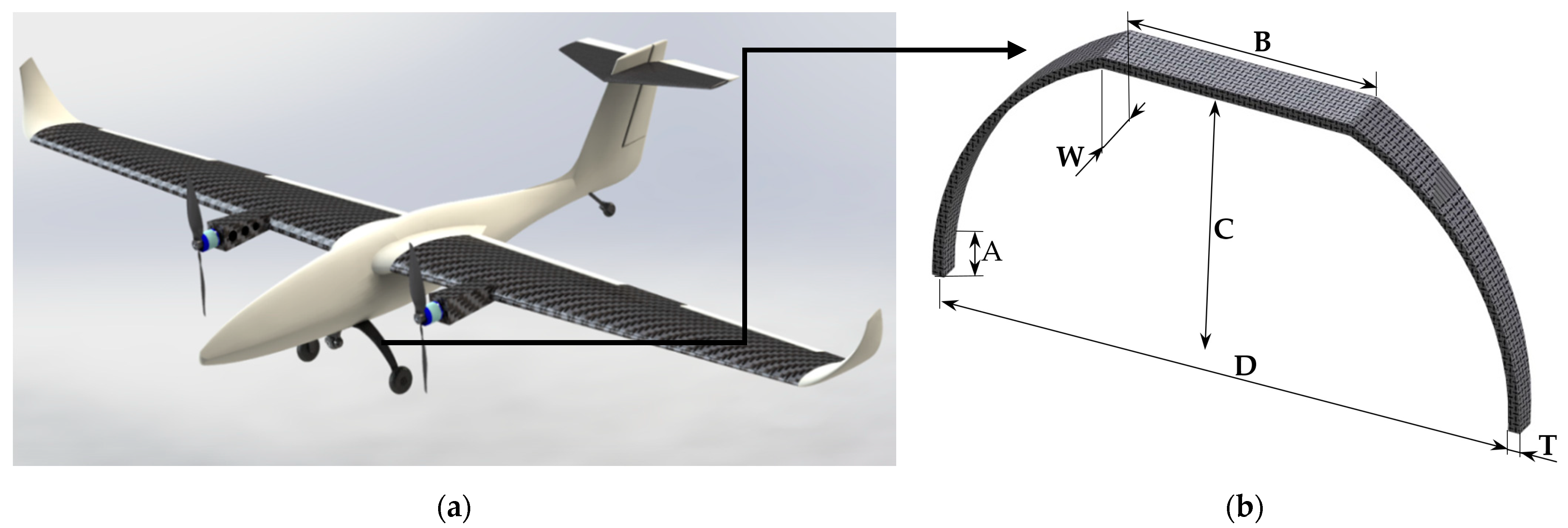
2.1. Landing Gear Design

The experimental UAV model (Figure 1a) has a wingspan of 3300 mm, with a positioning of the wing in the upper part of the fuselage. The fuselage has a frame and skin structure, and the tail has a T configuration. The landing gear of the UAV aircraft will make it possible to run it safely on the ground without damaging the aircraft during take-off and landing. The landing gear configuration chosen for this aircraft is the tricycle fixed landing gear, composed of a main wheel landing gear (Figure 1b) and a tail wheel landing gear. The landing gear was designed using SolidWorks 2021 (Dassault Systèmes SolidWorks Corporation, Waltham, MA, USA), considering the stress it will be subjected to during UAV airplane operation, especially during take-off and landing.
The dimensions of the main wheel landing gear, on which the two main wheels are mounted, are shown in Figure 1b and Table 1.

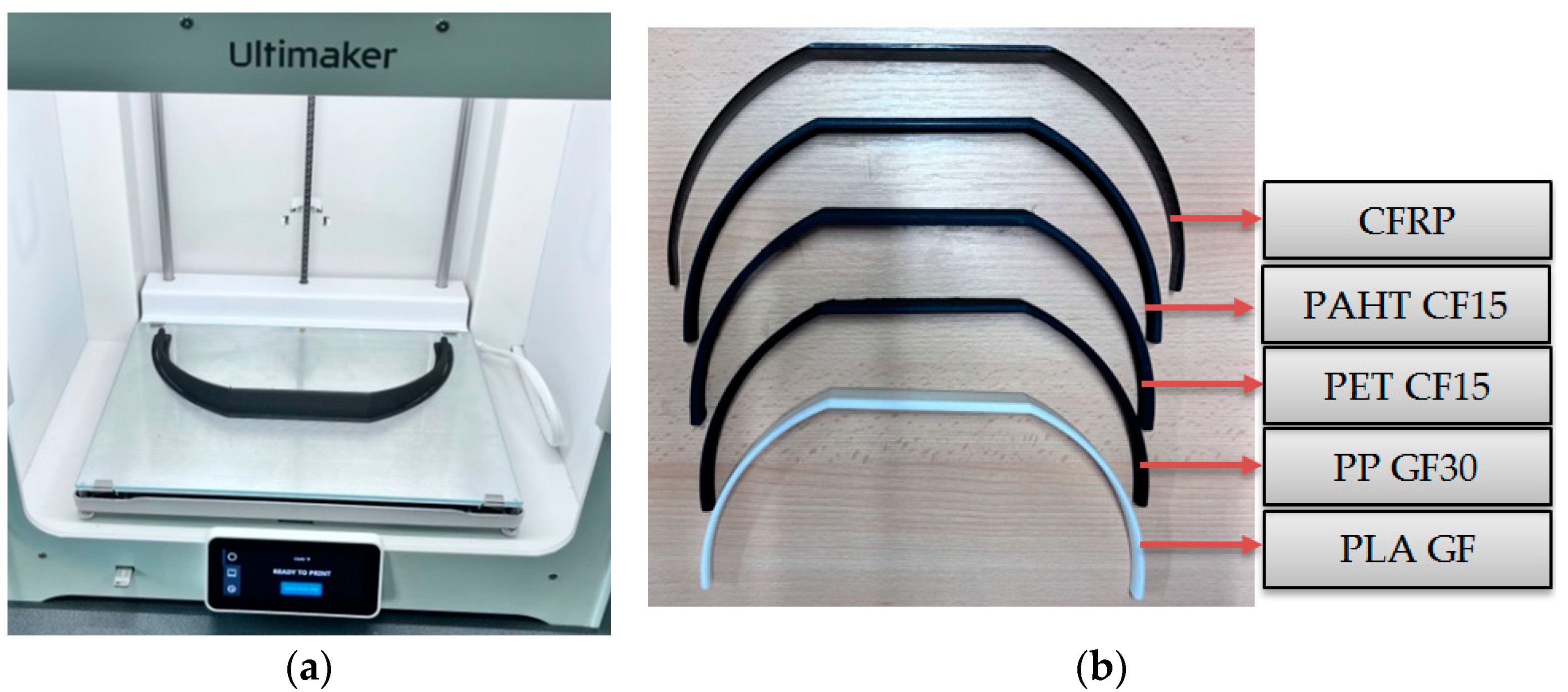
2.2. Landing Gear Models Manufactured by FFF Process

The landing gear models (Figure 2a) were manufactured on an Ultimaker S5 3D printer (Ultimaker, Utrecht, The Netherlands), from several types of filaments (Figure 2b), as follows:
  • Polylactic acid matrix reinforced with short glass fibers (PLA GF) has good chemical and mechanical resistance, is mixed up to 20% with short glass fibers, has high durability and can sustain temperatures of up to 100 °C. The fiberglass-reinforced filament is significantly stronger, harder and more heat resistant than regular PLA [31].
  • Polypropylene matrix reinforced with short glass fibers (PP GF30) is made of polypropylene, is reinforced with 30% glass fiber content and has a high heat resistance and an improved UV resistance. Due to its exceptional rigidity, this material is highly suitable for demanding applications [32].
  • Polyethylene terephthalate matrix reinforced with short carbon fibers (PET CF15) is a carbon-fiber-reinforced PET that has good strength and stiffness, high heat resistance, high dimensional stability and low abrasiveness. Due to its properties, this material can be used for a wide range of technical applications [33].
  • Polyamide matrix reinforced with short carbon fibers (PAHT CF15) is a thermoplastic reinforced with 15% carbon fibers that combines resistance to high temperatures and chemicals with special mechanical properties. With a peak temperature of 180 °C, this material can withstand constant temperatures of 150 °C [34].
  • High-quality carbon-fiber-reinforced polymer (CFRP) is a material in which carbon fiber is used as the reinforcement element in a polymer matrix [35]. When compared to any conventional polymer or metal, CFRP has excellent strength and low specific weight characteristics, damage tolerance and fatigue resistance [36]. An important advantage of using a high-quality carbon fiber-reinforced polymer (CFRP) for the landing gear is that this material has a very good mechanical strength resistance and a low mass. The carbon fiber landing gear, without mounting holes, is wrapped in a 3K cloth layup and pressed in a polished mold. The CFRP landing gear was manufactured using 6 layers of carbon fiber, with 0- and 90-degree fiber orientations.
The mechanical and thermal properties of materials used to obtain the landing gear models, manufactured by the FFF process, are described in Table 2.
All filaments used in the printing process have the manufacturing parameters presented in Table 3 and were utilized in the state delivered by the manufacturer without being subjected to thermal procedures. By exception, for the FFF process of the landing gear manufactured with PAHT CF15 filament, it was pre-dried at 70 °C for 12 h, according to the manufacturer’s specifications, using the Wanhao Box 2 dryer (Wanhao, Jinhua, China). The properties of the materials used are given by the filament suppliers. In order to present a more realistic picture of the mechanical performances, in the field of aviation, tests are carried out on real products. The thickness in the case of the 5 landing gear models was the same. Landing gear models were manufactured by the FFF process from filaments reinforced with short glass/carbon fibers that have high mechanical characteristics and are used in the aviation field for the manufacture of UAVs or components for small aircraft. Landing gear models were manufactured with 100% infill density because they represent vital components of UAVs and require the highest strength possible.

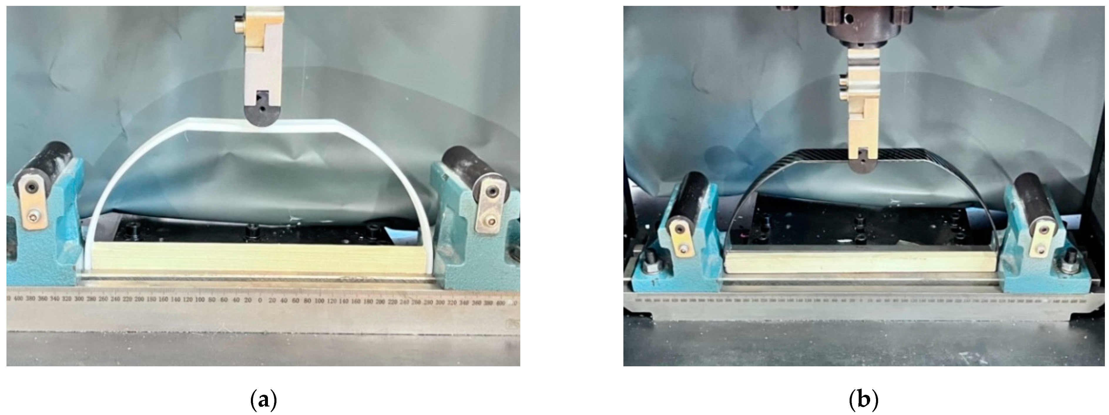
2.3. Three-Point Bending of the FFF-Manufactured Landing Gear Models

In order to establish the influence of the material type on the three-point bending properties of FFF-manufactured landing gears, a WDW-150S test machine (Jinan Testing Equipment IE Corporation, Jinan, China) was used. The three-point bending test was conducted, using a distance between the two supporting rollers of 325 mm, with a supporting roller diameter of 50 mm at a crosshead speed of 5 mm/min (Figure 3a,b). These tests were performed to determine the mechanical performance (bending strength) of composite landing gear models manufactured by the FFF process. The mechanical properties (bending strength) were calculated with the standardized calculation relationships of the three-point bending tests introduced by the manufacturer in the software of the test equipment, by inserting the dimensions of the component tested by the operator. The bending strength (σb) values of the landing gear models were determined using the following relations:
σ b = 3 PS 2 bd 2
where P is the force at a given point on the load–deflection curve (N); S is the length of support span (mm); b is the landing gear width (mm); d is the landing gear thickness (mm); Bending test of the landing gear models was carried out according to the following assumption: on the upper face B, the stress is applied. In reality, the landing gear will be fixed to the lower part of the fuselage exactly on this side B by the screw and nut.

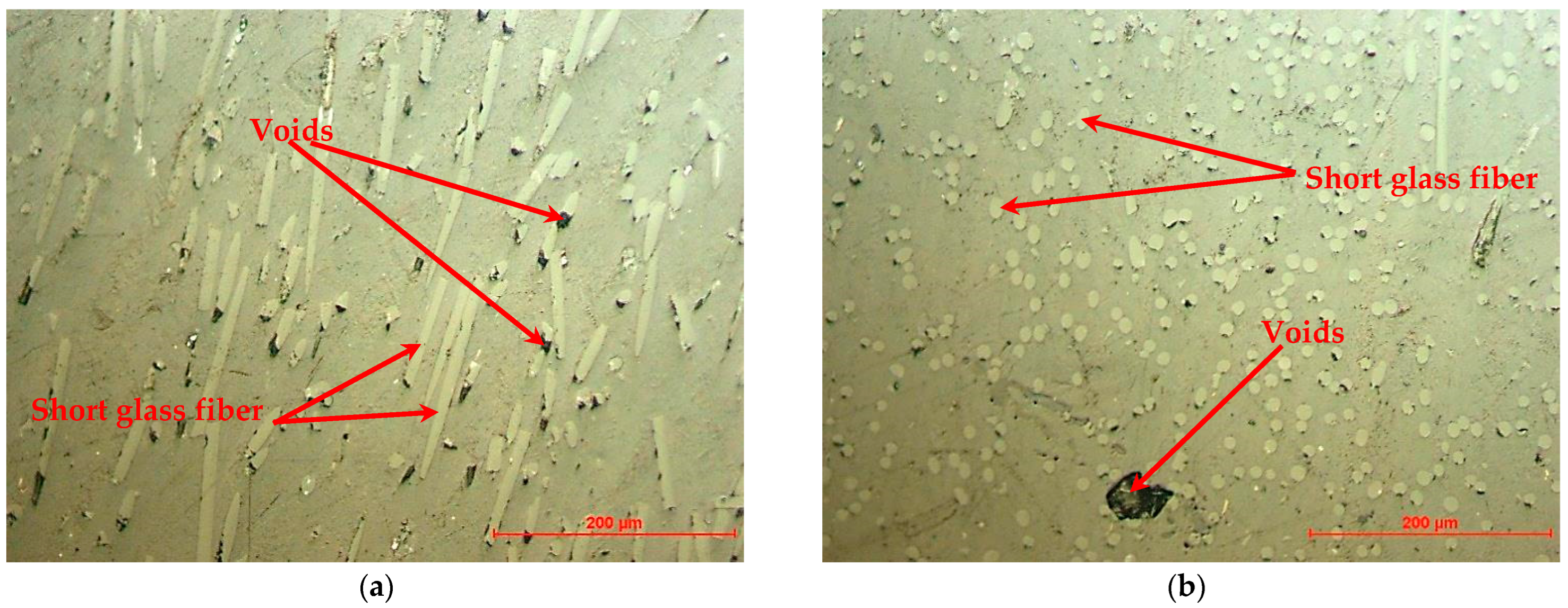
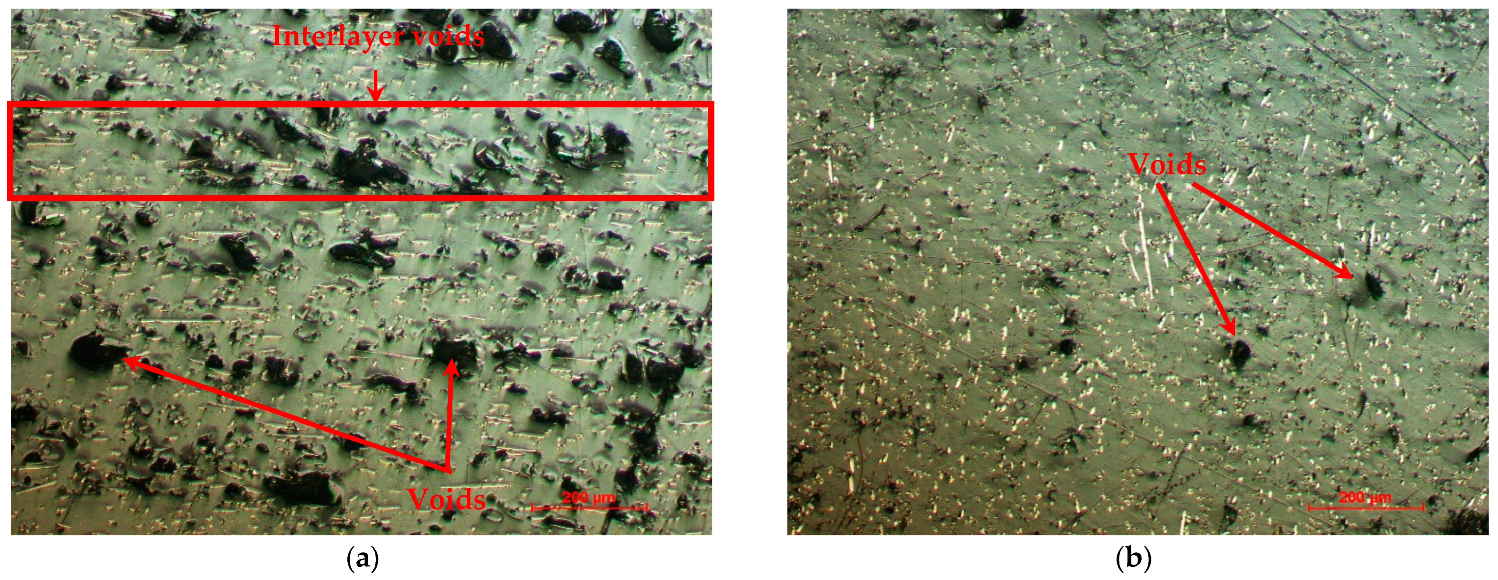
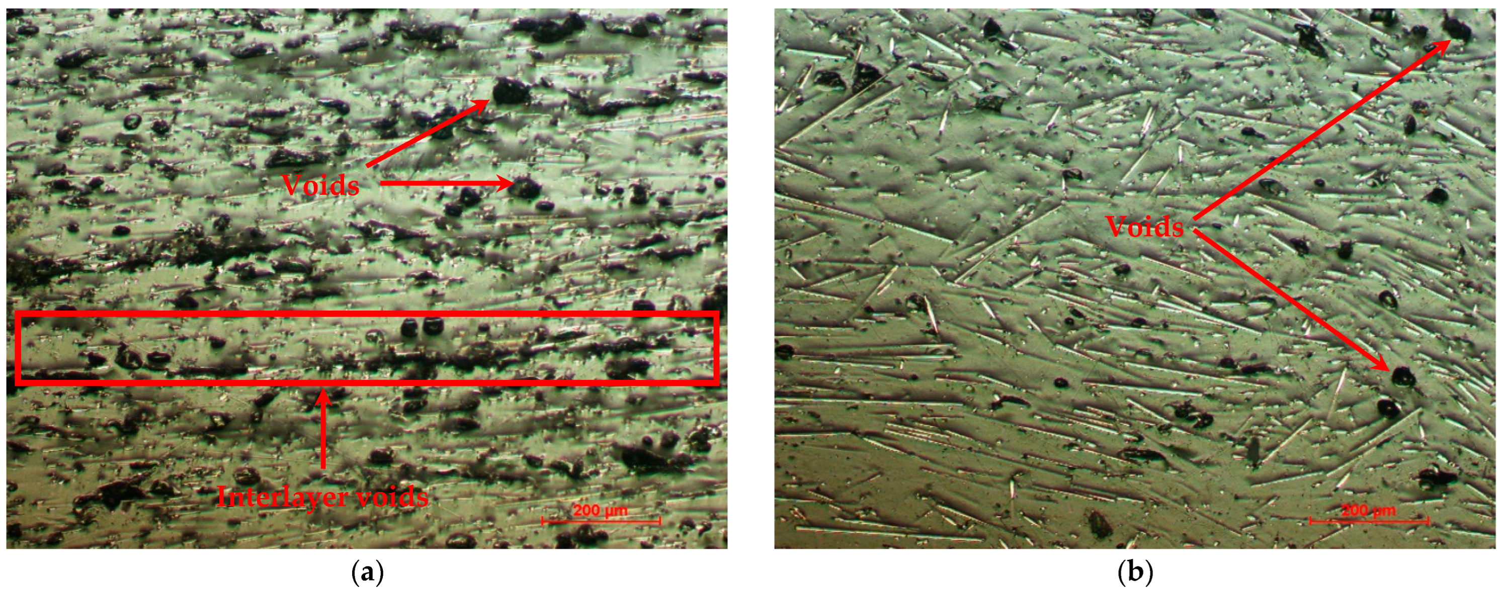
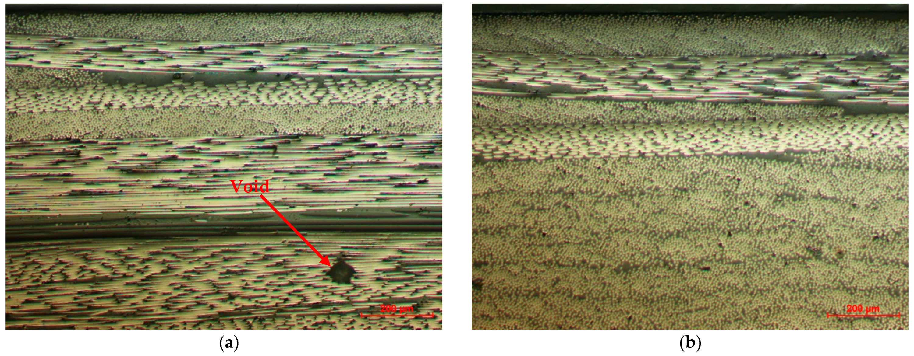
2.4. Microscopic Analysis of the Tested Models

To conduct microscopic analysis, specimens from each of the landing gears were taken on cross-sections (the sections perpendicular to the XY plane) and longitudinal sections (the Z building direction), embedded in acrylic resin and using an automatic metallographic Phoenix Beta polishing device from Buehler with Al2O3 suspension and 0.05 μm grit. Afterward, microscopic analysis was performed using a Nikon Eclipse MA 100 microscope (Nikon Corp., Tokyo, Japan).

3. Results and Discussion

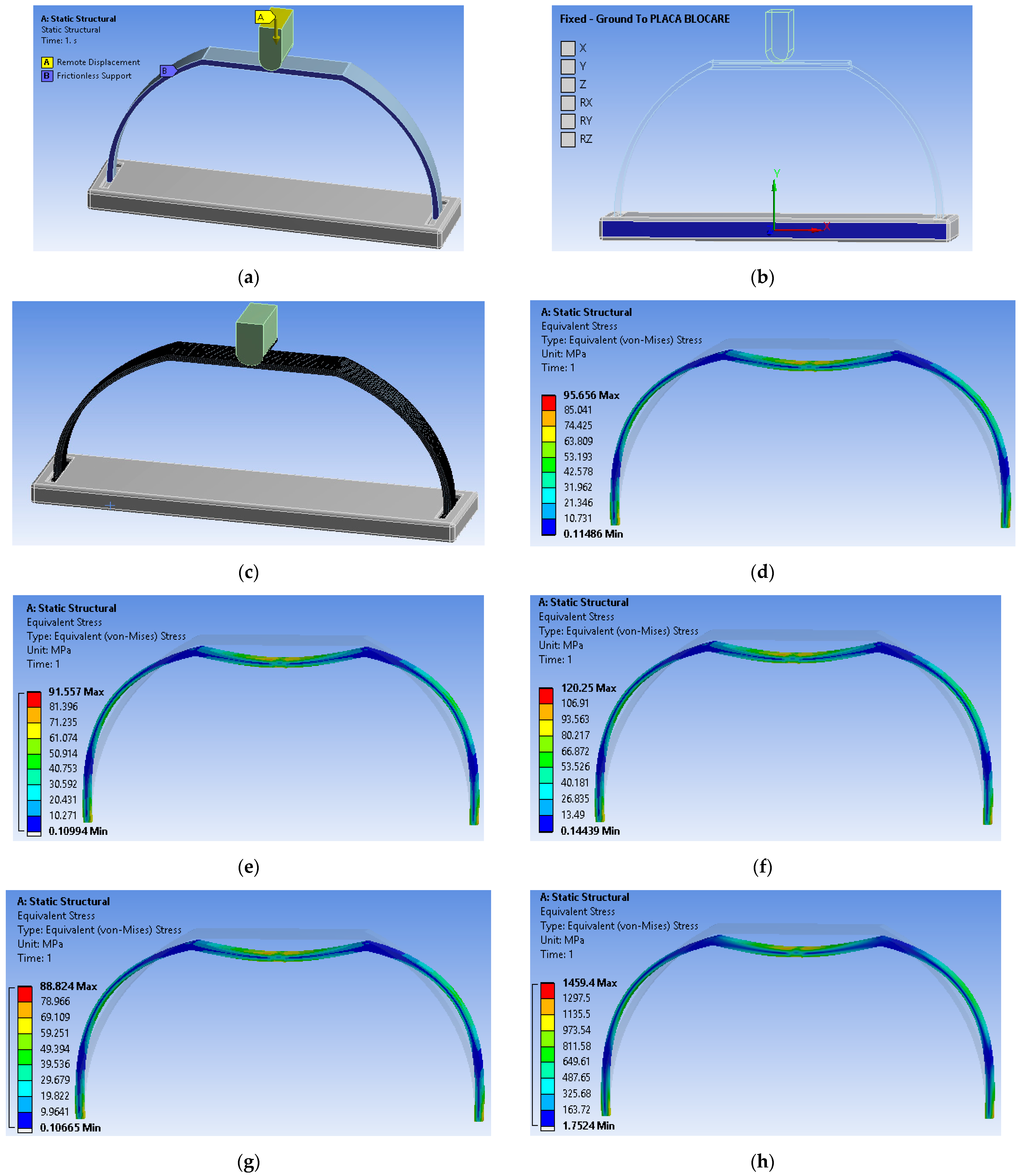
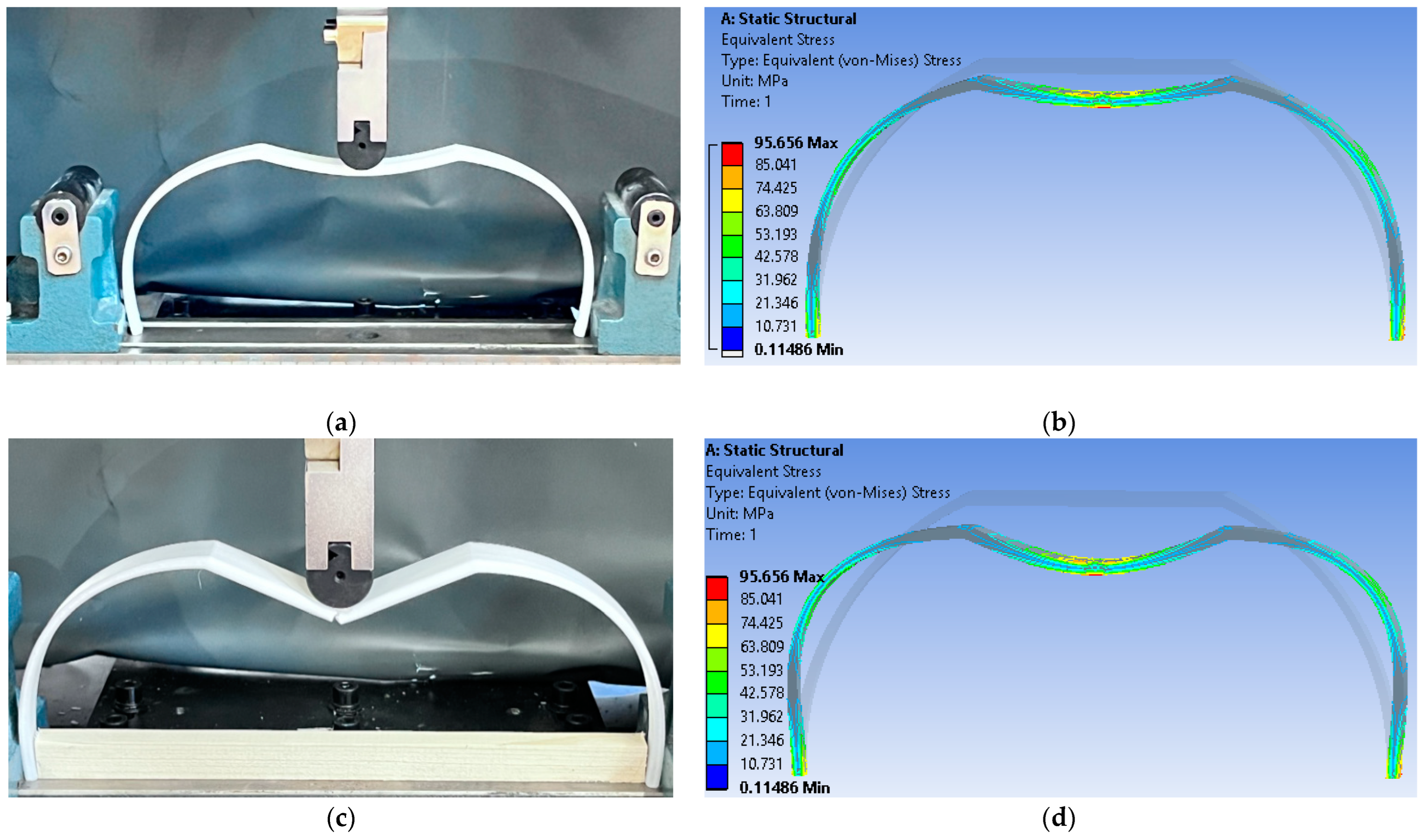
3.1. Finite Element Analysis of the Landing Gear

The finite element analysis of the landing gear models was performed in the Static Structural module of the ANSYS 2021 R2 software system (ANSYS, Inc., Canonsburg, PA, USA). In the finite element analysis of the landing gear, the conditions of the experimental tests (three-point bending) were respected, considering the dimensions and constraints of the test machine. The most significant constraints imposed on the finite element analysis were the dimensions of the landing gear model, the properties of the five types of material (PLA GF, PP GF30, PET CF15, PAHT CF15, CFRP), the radius of the punch, the radius of the fixing plate and the distance between supports. The three-point bending finite element analysis of the landing gear models was carried out, considering two major objectives:
  • The comparative analysis of the failure behavior obtained from the finite element analysis of landing gear models and the behavior observed during the experimental tests of the same models;
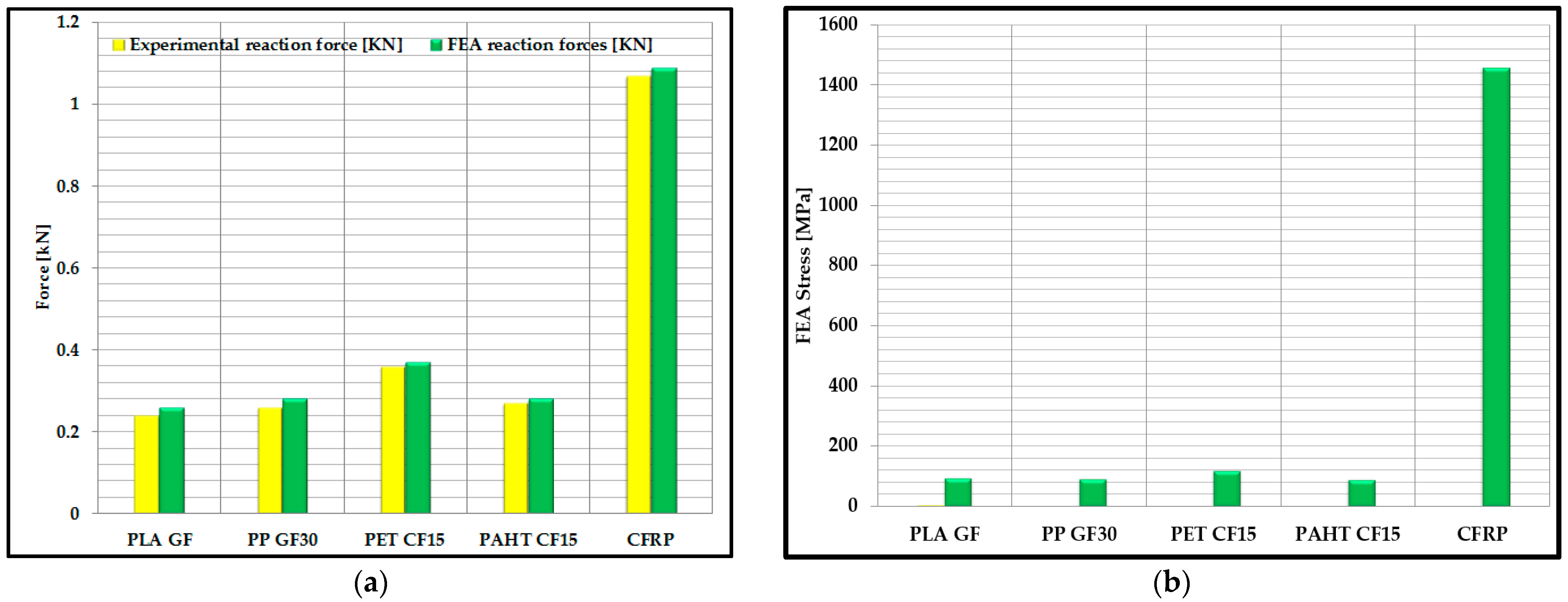
  • A comparative analysis of the maximum reaction forces that appear in the fixing’s structure plate from the finite element model and the reaction forces appearing at the break of the landing gear models.
In the finite element analysis, frictionless support type boundary conditions (Figure 4a) were established for the landing gear in order to prevent rotation throughout the simulation. In order to simulate the conditions of the experimental testing, a displacement request was issued through the machine bed, in the middle of the landing gear, with a value of 5 mm/min (Figure 4a).
The machine bed and the ground plate were assigned rigid body characteristics, and a fixed condition was established for the ground plate using the body-ground fixed joint option (Figure 4b). For the three-point bending simulation of the landing gear models, a discretization with three-dimensional elements of the Hexa type, with an element size of 1 mm, was used in FEA (Figure 4c). The punch and fixture plates were discretized using the same Hexa element type, having an element size of 2 mm (Figure 4c). A friction coefficient of 0.1 was established between the punch, the landing gear model and the mounting plate [37]. For the finite element analysis, the elastoplastic model was used, and the landing gear models were studied for 100% infill density. In this study, for the FEA simulation of the landing gear models, several simplifying assumptions were established and used in other studies too [38,39,40,41]: the constituents show a linear elastic behavior, the matrix (PAHT CF15—polyamide; PET CF15—polyethylene terephthalate; PLA GF—polylactic acid; PP GF30—polypropylene) has isotropic properties, short carbon/glass fibers are transversely isotropic, and the fiber matrix shows perfect adhesion and does not contain voids or defects.
The values of modulus of elasticity and Poisson’s ratio used in the material’s definition, as well as in previous research [38,39,42], which is focused on FEA simulation, are outlined in Table 4.
As a result, the outputs of the von Mises equivalent stress distribution on the landing gear models (Figure 4d–h) clearly identify the areas where the equivalent stress presents the highest values. From Figure 4d–h, it can be deduced that the maximum stresses that occur appear in the location where the loading is applied, and the two arms show a structural deformation on the outside called buckling by bending.

3.2. Mechanical Testing of the Landing Gear

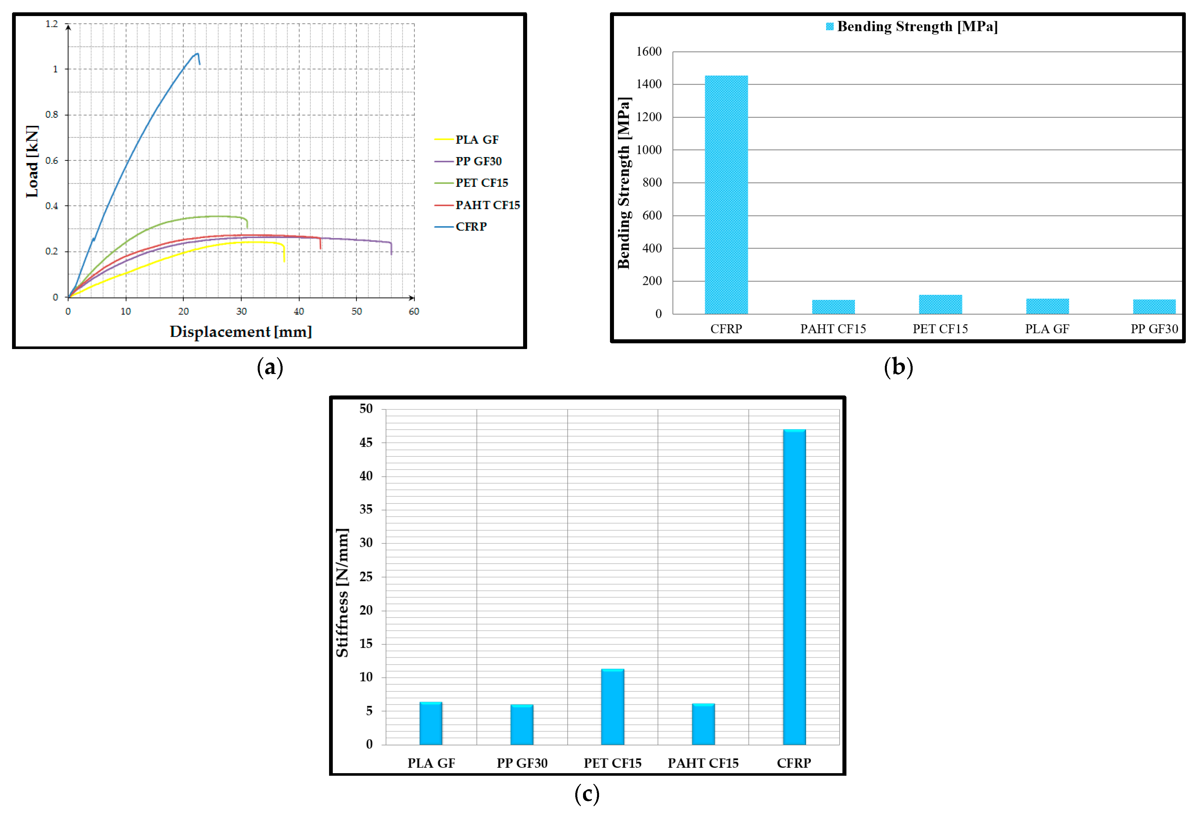
3.2.1. Three-Point Bending Testing of Landing Gear Models

A comparative study of the bending behaviors of five different composite materials was carried out in order to establish the material influence on the landing gear strength. The data obtained during the three-point bending tests were determined, and the load–displacement curves for the landing gears made of PLA GF, PP GF30, PET CF15, PAHT CF15 and CFRP are shown in Figure 5a.
After analyzing the aspect of the load–displacement curves, a difference was found between the mechanical behavior of the analyzed materials. All four FFF-manufactured landing gears exhibit three different phases:
  • In the first phase, a linear elastic behavior was observed: the increase in force is matched by a minor displacement;
  • In the second phase, the force has a small increase, while the displacement values increase significantly.
The third phase comprises the final range of the curve where the sudden rupture of the landing gear occurs.
For the CFRP material is found the lack of the second phase, demonstrating that the components of this material remain solid until the moment of breakage.
After comparing the results obtained from the three-point bending tests, it is found that FFF-manufactured landing gear has similar bending strengths (except for PET CF15, which has a slightly better strength) but is clearly inferior to CFRP. The results shown in Figure 5b represent the values of the bending strength for all of the components tested during three-point bending. After examining the results of the three-point bending test, the following conclusions were drawn:
  • All four FFF-manufactured landing gears have bending strength ranges between 88 MPa (PAHT CF15) and 118 MPa (PET CF15). Among them, PET CF15 has the best properties, with a bending strength 25% higher than PAHT CF15.
  • With a bending strength of 1455 MPa (12.3 times more than PETCF 15), CFRP has the best stiffness of all the materials used to build the landing gear.
In Figure 5c, stiffness was determined as the ratio between the force applied to the displacement of the landing gear models. It can be observed that the CFRP landing gear presented the highest value (approximately 47 N/mm), and among the landing gear models manufactured by the FFF process, the PET CF15 model had the highest stiffness (approximately 12 N/mm).
The conclusion of the three-point bending study is that the landing gear made of CFRP has the best mechanical performance among all the analyzed materials.

3.2.2. Comparative Analysis of Experimental Results vs. FEA

Thus, after carrying out the three-point bending tests of the landing gear models and from the analysis with finite elements (Figure 6a–d), it can be highlighted that the fracture of the analyzed gear models, in both cases, occurs in the lower skin area, roughly adjacent to the loading application area. In this lower zone, the structure is subjected to stresses with a maximum value of von Mises equivalent stress of 95 MPa (Figure 6b,d).
In Figure 7a, the stress results obtained with the FEA analysis and the experimental tests are described, from which it can be deduced that the values are close, which validates the initial calculation model and the finite element analysis. The stress is the measure of an external force acting over the cross-sectional area of the landing gear models.
It can be noted that there is a validation between the deformation mode from the FEA analysis and the deformation mode from the experimental tests of the landing gear models, as shown in Figure 6a–d. Therefore, in the first stage, the landing gear takes over the load and starts to deform both in the central area, where the stress is applied and in the area of the arms which are subjected to the phenomenon of buckling by bending. The deformation mode, from the analysis with finite elements, is highlighted in Figure 6b,d, in which the initial shape and the final shape of the landing gear reaction behavior, when applying the stress, are presented. In future research by the authors, the energy method will be used to calculate the deflection of the landing gear models.
In relation to the third objective of the finite element analysis, the comparative study between the maximum reaction forces that appeared within the analysis with finite elements and the maximum reaction forces obtained from the rupture of the landing gear models can be stated to provide an adequate validation of the results (Figure 7b).
After a closer analysis of the results regarding the maximum reaction forces for the five models of the landing gear, it can be concluded that the error is less than 2%. This relative error is accepted in the aviation field and normally occurs because of the simplifying assumptions stated above.

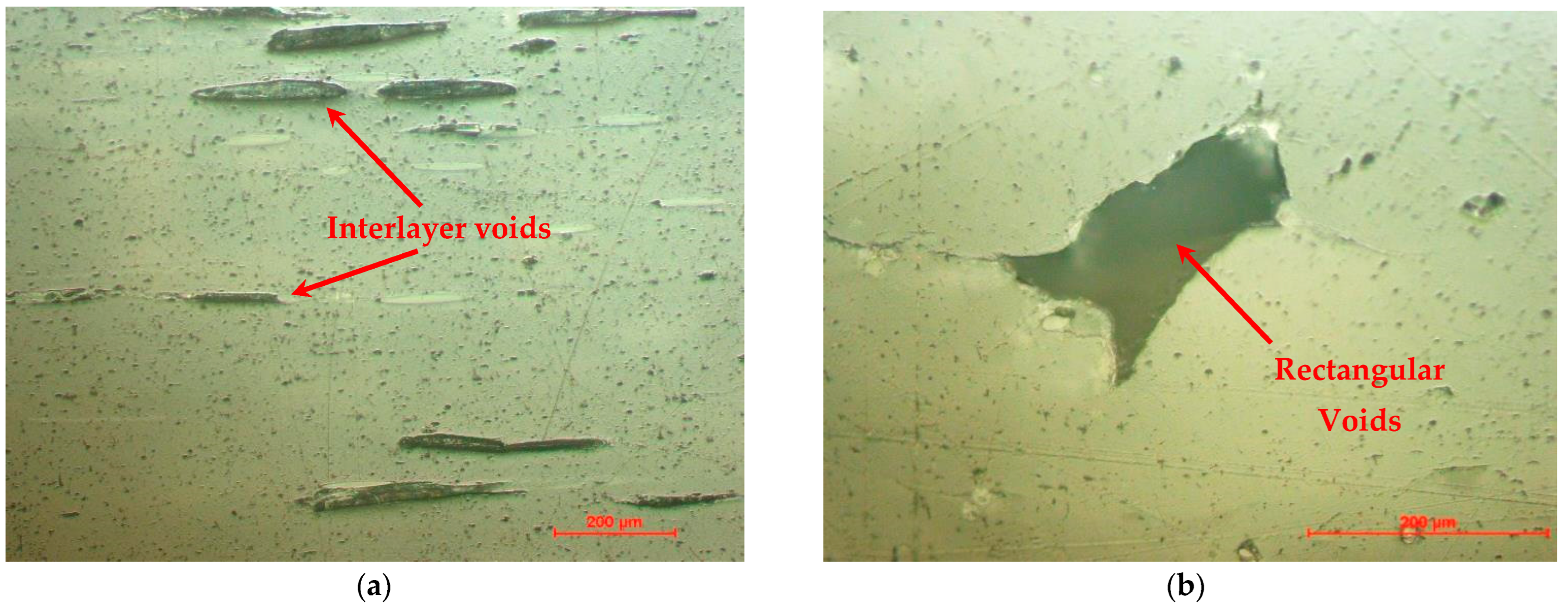
3.3. Failure Mode Analysis of the Tested Models

The distribution and orientation of the fibers in the polymer matrix, the presence of voids and deposition defects, or the appearance of microcracks in the material microstructure are some of the main defects specific to the FFF process for composite filaments reinforced with short carbon fiber. In order to highlight these main defects, representative samples were taken from the landing gears to be prepared for structural and morphological analysis. In this regard, the samples have been cross-sectioned and longitudinally sectioned, embedded into acrylic resin and polished.
In the case of the landing gear made of PLA GF, it was found that interlayer voids (Figure 8a) appeared between the layers of extruded material but also typical voids that appear in the case of filaments with short fibers such as rectangular voids (Figure 8b). In the microscopic images of the PP GF30 landing gear, the following can be observed: the gray lines (Figure 9a) or gray dots (Figure 9b) represent the glass fibers, and the darker areas represent voids from the FFF manufacturing process of the PP GF30 filament. It was observed that this PP GF30 (glass fiber reinforced) filament showed much fewer defects compared to carbon-fiber-reinforced filaments analyzed in other studies [43,44,45].
Figure 10 and Figure 11 show that the distribution of carbon fibers in the polymer matrix is approximately uniform, having an orientation along the deposition direction similar to those published in other studies [43,44,45,46]. After analyzing the microstructure, the appearance of defects, such as voids and interlayer voids, was observed. Following the microscopic analyses of the landing gear models fabricated by filaments reinforced with carbon fiber, the following can be observed: the white lines or the white dots represent the carbon fibers, and the darker areas represent voids or interlayer voids that come from the FFF process of landing gears.
From the microscopic analysis of the CFRP landing gear in the longitudinal section and in the cross-section were observed the following: interlayer region, carbon fiber alignment, and the orientation of the carbon fibers and the carbon fiber are distributed uniformly in the resin. Of course, even in this case, a defect (void) can be observed that occurred in the manufacturing process of the CFRP landing gear (Figure 12).
The conclusions that can be drawn after completing the microscopic analysis of the investigated materials are:
  • Typical defects of short fiber-reinforced composites were found, similar to those published in other studies [43,44,45,46,47,48];
  • The formation of elongated interlayer voids or voids of any shape found in the matrix or filament [49];
  • Regarding the orientation of the carbon fibers, in most materials, the orientation of the carbon fibers along the deposition direction can be observed [48].

4. Conclusions

The benefits of using a CAD system that can be coupled with various additive manufacturing technologies, such as the low production cost, the high design flexibility, or the ability to produce complex shapes without being constrained by manufacturing constraints, have made the use of these techniques more and more popular for UAV manufacturing, ranging from hobbies to military purposes. The lightweight and moderate dimensions of UAV components make it possible to use FFF-processed polymers for their manufacture, thus benefiting from all the above-mentioned advantages. The limited loads and moderate dimensions of the frames make those parts compatible with FFF-processed polymers.
In this paper, five landing gear models for an unmanned aircraft manufactured from different materials, three from carbon fiber and two from glass fiber, using the FFF process and molding process (for CFRP landing gear), are analyzed. All these components are made of filaments with short fibers (chopped fibers). Following the design of the landing gear and the analysis of the results obtained from the FEA analysis and the experimental tests to which the five models produced from various materials were subjected in order to establish the landing gear with the best mechanical strength as well, the following conclusions can be drawn: in the finite element analysis of the landing gear, performed in the Static Structural module of the ANSYS 2021 R2 software system, the conditions of the experimental tests (three-point bending) were respected, considering the dimensions and constraints of the testing machine. With the outputs of the von Mises equivalent stress distribution on the landing gear models were identified the areas where the equivalent stress presents the highest values. The load–displacement curves for the landing gears built of PLA GF, PP GF30, PET CF15, PAHT CF15 and CFRP were generated using the data gathered during the three-point bending tests. The mean values of the bending strength for all of the models tested at bending in three points were determined. After carrying out the three-point bending tests of the landing gear models and from the analysis with finite elements, it can be highlighted that the fracture of the analyzed gear models, in both cases, occurs in the lower skin area, roughly adjacent to the loading application area. Physical models were tested in three-point bending followed by microscopic analysis to detect manufacturing defects. Finally, a comparative study of the preliminary results obtained by simulation with the finite element analysis method and the experimental results obtained following the bending test of the landing gear models was carried out.
The final conclusion reached after analyzing all of the results provided by both physical tests and computer simulations is that in the case of UAVs or drones, the landing gear can be manufactured using the FFF process, but in the case of a light airplane, a CFRP landing gear must be used. If the UAV’s material allows for the fabrication of landing gear through additive manufacturing, the material must have the highest mechanical strength of the four materials studied, namely PET CF15.

Author Contributions

Conceptualization, C.L. and S.-M.Z.; methodology, S.-M.Z., M.-A.P., L.-A.C. and I.S.P.; software, G.-R.B. and C.L.; validation, C.L. and V.-M.S.; investigation, C.L., S.-M.Z., M.-A.P. and G.-R.B.; writing—original draft preparation, C.L., G.-R.B., S.-M.Z., L.-A.C. and I.S.P.; project administration, S.-M.Z. All authors have read and agreed to the published version of the manuscript.

Funding

This work was supported by a grant of the Ministry of Research, Innovation and Digitization, CNCS/CCCDI—UEFISCDI, Project Number PN-III-P2-2.1-PED-2019-0739, within PNCDI III.

Institutional Review Board Statement

Not applicable.

Informed Consent Statement

Not applicable.

Data Availability Statement

Not applicable.

Acknowledgments

We also acknowledge the PRO-DD Structural Funds Project (POS-CCE, O.2.2.1., ID 123, SMIS 2637, Ctr. No. 11/2009) for providing the infrastructure used in this work.

Conflicts of Interest

The authors declare no conflict of interest.

References

  1. Albatayneh, A.; Assaf, M.N.; Alterman, D.; Jaradat, M. Comparison of the Overall Energy Efficiency for Internal Combustion Engine Vehicles and Electric Vehicles. Environ. Clim. Technol. 2020, 24, 669–680. [Google Scholar]
  2. Zimakowska-Laskowska, M.; Laskowski, P. Emission from Internal Combustion Engines and Battery Electric Vehicles: Case Study for Poland. Atmosphere 2022, 13, 401. [Google Scholar] [CrossRef]
  3. Erd, A.; Stoklosa, J. Energy Dependencies in Li-Ion Cells and Their Influence on the Safety of Electric Motor Vehicles and Other Large Battery Packs. Energies 2020, 13, 6738. [Google Scholar] [CrossRef]
  4. Sujit, P.B.; Ghose, D. Search using multiple UAVs with flight time constraints. IEEE Trans. Aerosp. Electron. Syst. 2004, 40, 491–510. [Google Scholar] [CrossRef]
  5. Sarunic, P.; Evans, R. Hierarchical model predictive control of UAVs performing multitarget-multisensor tracking. IEEE Trans. Aerosp. Electron. Syst. 2014, 50, 2253–2268. [Google Scholar] [CrossRef]
  6. Campi, T.; Cruciani, S.; Maradei, F.; Feliziani, M. Innovative Design of Drone Landing Gear Used as a Receiving Coil in Wireless Charging Application. Energies 2019, 12, 3483. [Google Scholar] [CrossRef]
  7. Cerro, J.d.; Cruz Ulloa, C.; Barrientos, A.; de León Rivas, J. Unmanned Aerial Vehicles in Agriculture: A Survey. Agronomy 2021, 11, 203. [Google Scholar] [CrossRef]
  8. Jayalakshmi, C.G.; Inamdar, A.; Anand, A.; Kandasubramanian, B. Polymer matrix composites as broadband radar absorbing structures for stealth aircrafts. J. Appl. Polym. Sci. 2019, 136, 47241. [Google Scholar] [CrossRef]
  9. Seo, J.; Duque, L.; Wacker, J. Drone-enabled bridge inspection methodology and application. Autom. Constr. 2018, 94, 112–126. [Google Scholar] [CrossRef]
  10. Ding, J.; Mei, H.; I, C.-L.; Zhang, H.; Liu, W. Frontier Progress of Unmanned Aerial Vehicles Optical Wireless Technologies. Sensors 2020, 20, 5476. [Google Scholar] [CrossRef]
  11. Liang, Y.C.; Chin, P.C.; Sun, Y.P.; Wang, M.R. Design and Manufacture of Composite Landing Gear for a Light Unmanned Aerial Vehicle. Appl. Sci. 2021, 11, 509. [Google Scholar] [CrossRef]
  12. Wrobel, R.; Mecrow, B.C. A Comprehensive review of additive manufacturing in construction of electrical machines. IEEE Trans. Energy Convers. 2020, 35, 1054–1064. [Google Scholar] [CrossRef]
  13. Barroqueiro, B.; Andrade-Campos, A.; Valente, R.A.F.; Neto, V. Metal Additive Manufacturing Cycle in Aerospace Industry: A Comprehensive Review. J. Manuf. Mater. Process. 2019, 3, 52. [Google Scholar] [CrossRef]
  14. Culmone, C.; Smit, G.; Breedveld, P. Additive manufacturing of medical instruments: A state-of-the-art review. Addit. Manuf. 2019, 27, 461–473. [Google Scholar] [CrossRef]
  15. Wiese, M.; Thiede, S.; Herrmann, C. Rapid manufacturing of automotive polymer series parts: A systematic review of processes, materials and challenges. Addit. Manuf. 2020, 36, 101582. [Google Scholar] [CrossRef]
  16. Ghahfarokhi, P.S.; Podgornovs, A.; Kallaste, A.; Cardoso, A.J.M.; Belahcen, A.; Vaimann, T.; Tiismus, H.; Asad, B. Opportunities and Challenges of Utilizing Additive Manufacturing Approaches in Thermal Management of Electrical Machines. IEEE Access 2021, 9, 36368–36381. [Google Scholar] [CrossRef]
  17. Stergiou, V.; Konstantopoulos, G.; Charitidis, C.A. Carbon Fiber Reinforced Plastics in Space: Life Cycle Assessment towards Improved Sustainability of Space Vehicles. J. Compos. Sci. 2022, 6, 144. [Google Scholar] [CrossRef]
  18. Mahesh, V.; Joladarashi, S.; Kulkarni, S.M. A Comprehensive Review on Material Selection for Polymer Matrix Composites Subjected to Impact Load. Def. Technol. 2021, 17, 257–277. [Google Scholar] [CrossRef]
  19. Goh, G.D.; Toh, W.; Yap, Y.L.; Ng, T.Y.; Yeong, W.Y. Additively Manufactured Continuous Carbon Fiber-Reinforced Thermoplastic for Topology Optimized Unmanned Aerial Vehicle Structures. Compos. Part B Eng. 2021, 216, 108840. [Google Scholar] [CrossRef]
  20. MohamedZain, A.O.; Chua, H.; Yap, K.; Uthayasurian, P.; Jiehan, T. Novel Drone Design Using an Optimization Software with 3D Model, Simulation and Fabrication in Drone Systems Research. Drones 2022, 6, 97. [Google Scholar] [CrossRef]
  21. Pascariu, I.S.; Zaharia, S.M. Design and testing of an unmanned aerial vehicle manufactured by fused deposition modeling. J. Aerosp. Eng. 2020, 33, 06020002. [Google Scholar] [CrossRef]
  22. Dua, R.; Rashad, Z.; Spears, J.; Dunn, G.; Maxwell, M. Applications of 3D-Printed PEEK via Fused Filament Fabrication: A Systematic Review. Polymers 2021, 13, 4046. [Google Scholar] [CrossRef] [PubMed]
  23. Wang, F.; Zhang, Z.; Ning, F.; Wang, G.; Dong, C. A mechanistic model for tensile property of continuous carbon fiber reinforced plastic composites built by fused filament fabrication. Addit. Manuf. 2020, 32, 101102. [Google Scholar] [CrossRef]
  24. Rijckaert, S.; Daelemans, L.; Cardon, L.; Boone, M.; Van Paepegem, W.; De Clerck, K. Continuous Fiber-Reinforced Aramid/PETG 3D-Printed Composites with High Fiber Loading through Fused Filament Fabrication. Polymers 2022, 14, 298. [Google Scholar] [CrossRef] [PubMed]
  25. Setlak, L.; Kowalik, R.; Lusiak, T. Practical Use of Composite Materials Used in Military Aircraft. Materials 2021, 14, 4812. [Google Scholar] [CrossRef]
  26. Xue, Z.P.; Li, M.; Li, Y.H.; Jia, H.G. A simplified flexible multibody dynamics for a main landing gear with flexible leaf spring. Shock Vib. 2014, 2014, 595964. [Google Scholar] [CrossRef]
  27. Dong, X.M.; Xiong, G.W. Vibration attenuation of magnetorheological landing gear system with human simulated intelligent control. Math. Probl. Eng. 2013, 2013, 242476. [Google Scholar]
  28. Vignesh, A.S.; Vivek, A.A. Study on fatigue fracture failure of UAV landing gear. J. Mech. Eng. 2015, 6, 9–15. [Google Scholar] [CrossRef]
  29. Imran, M.; Shabbir Ahmed, R.M.; Haneefc, M. FE Analysis for Landing Gear of Test Air Craft. Mater. Today Proc. 2015, 2, 2170–2178. [Google Scholar] [CrossRef]
  30. Rashidi, A.; Milani, A.S. Finite Element Analysis of a Composite Landing Gear and Effect of Runway Material. In Proceedings of the Canadian Society for Mechanical Engineering International Congress, Kelowna, BC, Canada, 26–29 June 2016. [Google Scholar]
  31. Available online: https://filaticum.com/en/product/philament-glass-reinforced/ (accessed on 20 July 2022).
  32. Available online: https://www.ultrafusefff.com/product-category/innopro/ppgf30/ (accessed on 20 July 2022).
  33. Available online: https://www.ultrafusefff.com/product-category/innopro/petcf/ (accessed on 20 July 2022).
  34. Available online: https://www.ultrafusefff.com/product-category/innopro/paht-cf/ (accessed on 20 July 2022).
  35. Altin Karataş, M.; Gökkaya, H. A review on machinability of carbon fiber reinforced polymer (CFRP) and glass fiber reinforced polymer (GFRP) composite materials. Def. Technol. 2018, 14, 318–326. [Google Scholar] [CrossRef]
  36. Gaugel, S.; Sripathy, P.; Haeger, A. A comparative study on tool wear and laminate damage in drilling of carbon-fiber reinforced polymers (CFRP). Compos. Struct. 2016, 155, 173–183. [Google Scholar] [CrossRef]
  37. Hou, Z.; Fan, L.; Zhang, X.; Zhai, S.; Zhang, C.; Li, C.; Du, Y.; Zhao, H. Failure mechanism of brass with three V-notches characterized by acoustic emission in in situ three-point bending tests. Adv. Eng. Mater. 2016, 18, 1–10. [Google Scholar] [CrossRef]
  38. Ghebretinsae, F.; Mikkelsen, O.; Akessa, A.D. Strength analysis of 3D printed carbon fibre reinforced thermoplastic using experimental and numerical methods. IOP Conf. Ser. Mater. Sci. Eng. 2019, 700, 012024. [Google Scholar] [CrossRef]
  39. Sauer, M.J. Evaluation of the Mechanical Properties of 3D Printed Carbon Fiber Composites. Ph.D. Thesis, South Dakota State University, Brookings, SD, USA, 2018. [Google Scholar]
  40. Zyganitidis, I.; Arailopoulos, A.; Giagopoulos, D. Composite Material Elastic Effective Coefficients Optimization by Means of a Micromechanical Mechanical Model. Appl. Mech. 2022, 3, 779–798. [Google Scholar] [CrossRef]
  41. Zhang, N.; Gao, S.; Song, M.; Chen, Y.; Zhao, X.; Liang, J.; Feng, J. A Multiscale Study of CFRP Based on Asymptotic Homogenization with Application to Mechanical Analysis of Composite Pressure Vessels. Polymers 2022, 14, 2817. [Google Scholar] [CrossRef] [PubMed]
  42. Vemuganti, S.; Soliman, E.; Reda Taha, M. 3D-Printed Pseudo Ductile Fiber-Reinforced Polymer (FRP) Composite Using Discrete Fiber Orientations. Fibers 2020, 8, 53. [Google Scholar] [CrossRef]
  43. Tekinalp, H.L.; Kunc, V.; Velez-Garcia, G.M.; Duty, C.E.; Love, L.J.; Naskar, A.K.; Blue, C.A.; Ozcan, S. Highly oriented carbon fiber–polymer composites via additive manufacturing. Compos. Sci. Technol. 2014, 105, 144–150. [Google Scholar] [CrossRef]
  44. Belei, C.; Joeressen, J.; Amancio-Filho, S.T. Fused-Filament Fabrication of Short Carbon Fiber-Reinforced Polyamide: Parameter Optimization for Improved Performance under Uniaxial Tensile Loading. Polymers 2022, 14, 1292. [Google Scholar] [CrossRef]
  45. Lupone, F.; Padovano, E.; Venezia, C.; Badini, C. Experimental Characterization and Modeling of 3D Printed Continuous Carbon Fibers Composites with Different Fiber Orientation Produced by FFF Process. Polymers 2022, 14, 426. [Google Scholar] [CrossRef]
  46. Peng, X.S.; Zhang, M.M.; Guo, Z.C.; Sang, L.; Hou, W.B. Investigation of processing parameters on tensile performance for FDM-printed carbon fiber reinforced polyamide 6 composites. Compos. Commun. 2020, 22, 100478. [Google Scholar] [CrossRef]
  47. Zheng, Y.; Huang, X.; Chen, J.; Wu, K.; Wang, J.; Zhang, X. A Review of Conductive Carbon Materials for 3D Printing: Materials, Technologies, Properties and Applications. Materials 2021, 14, 3911. [Google Scholar] [CrossRef] [PubMed]
  48. Zaharia, S.M.; Pop, M.A.; Chicos, L.-A.; Buican, G.R.; Lancea, C.; Pascariu, I.S.; Stamate, V.-M. Compression and Bending Properties of Short Carbon Fiber Reinforced Polymers Sandwich Structures Produced via Fused Filament Fabrication Process. Polymers 2022, 14, 2923. [Google Scholar] [CrossRef] [PubMed]
  49. Buican, G.R.; Zaharia, S.-M.; Pop, M.A.; Chicos, L.-A.; Lancea, C.; Stamate, V.-M.; Pascariu, I.S. Fabrication and Characterization of Fiber-Reinforced Composite Sandwich Structures Obtained by Fused Filament Fabrication Process. Coatings 2021, 11, 601. [Google Scholar] [CrossRef]
Figure 1. Landing gear: (a) position on the UAV; (b) dimensions.
Applsci 12 08598 g001
Figure 2. Landing gear models: (a) manufactured by FFF process using PAHT-CF15 filament; (b) five models subjected to the three-point bending test.
Applsci 12 08598 g002
Figure 3. Three-point bending test for the landing gears made of: (a) PLA GF; (b) CFRP.
Applsci 12 08598 g003
Figure 4. Finite element analysis of landing gear models: (a,b) set up boundary conditions; (c) discretization of the model; (d) equivalent stress distribution for landing gear made of material PLA GF; (e) equivalent stress distribution for landing gear made of material PP GF30; (f) equivalent stress distribution for landing gear made of PET CF15 material; (g) equivalent stress distribution for landing gear made of material PAHT CF15; (h) equivalent stress distribution for landing gear made of CFRP material.
Applsci 12 08598 g004
Figure 5. Results after three-point bending tests: (a) load–displacement curves; (b) bending strength of the tested landing gear; (c) stiffness of landing gear models.
Applsci 12 08598 g005
Figure 6. Testing of the landing gear models includes the following scenarios: (a) intermediate stage during the PLA GF landing gear’s three-point bending test; (b) deformation mode of the PLA GF landing gear from the finite element analysis; (c) rupture of the PLA GF landing gear; (d) rupture of PLA GF landing gear simulation.
Applsci 12 08598 g006
Figure 7. Comparative study of experimental results and FEA results: (a) graphical representation of reaction forces; (b) graphical representation of FEA stresses.
Applsci 12 08598 g007
Figure 8. Microscopic analysis of the landing gear made of PLA GF: (a) longitudinal section (100×); (b) cross-section (100×).
Applsci 12 08598 g008
Figure 9. Microscopic analysis of the landing gear made of PP GF30: (a) longitudinal section (100×); (b) cross-section (100×).
Applsci 12 08598 g009
Figure 10. Microscopic analysis of the landing gear fabricated of PET CF15: (a) longitudinal section (100×); (b) cross-section (100×).
Applsci 12 08598 g010
Figure 11. Microscopic analysis of the landing gear manufactured of PAHT CF15: (a) longitudinal section (100×); (b) cross-section (100×).
Applsci 12 08598 g011
Figure 12. Microscopic analysis of CFRP landing gear: (a) longitudinal section (100×); (b) cross-section (100×).
Applsci 12 08598 g012
Table 1. Landing gear dimensions (3D printed and commercial aircraft landing gear).
AbbreviationNameDimensions (mm)
AWheel Mounting Surface20
BFuselage Width145
CLeg Height145
DWheel Track315
TThickness5
WWidth Landing Gear28
Table 2. Mechanical and thermal properties of filaments [31,32,33,34].
Mechanical and Thermal PropertiesPLA GFPP GF30PET CF15PAHT CF15
Tensile strength (MPa)9041.763.2103.2
Tensile modulus (MPa)4000262861788386
Flexural strength (MPa)11476.8108160.7
Flexural modulus (MPa)3700350754528258
Impact strength (kJ/m2)2923.127.820.6
Melting temperature (°C)165158245234
Table 3. Established parameters for manufacturing landing gear models by the FFF process.
Manufacturing ParameterPLA GFPP GF30PET CF15PAHT CF15
Filament diameter (mm)2.852.852.852.85
Infill density (%)100100100100
Layer height (mm)0.20.20.20.2
Print speed (mm/s)45454545
Travel speed (mm/s)150150150150
Printing temperature (°C)240250260260
Build plate temperature (°C)809580100
Table 4. Material characteristics used in FEA simulation.
MaterialElastic Modulus (MPa)Poisson’s Ratio
PLA GF40000.25
PP GF3035070.35
PET CF1554520.3
PAHT CF1583860.3
CFRP121,0000.4
Publisher’s Note: MDPI stays neutral with regard to jurisdictional claims in published maps and institutional affiliations.

