
Augmented Reality-Based Interface for Bimanual Robot Teleoperation


Instituto de Diseño y Fabricación, Universitat Politècnica de València, 46022 Valencia, Spain
*
Author to whom correspondence should be addressed.
Appl. Sci. 2022, 12(9), 4379; https://doi.org/10.3390/app12094379
Submission received: 21 March 2022
/
Revised: 23 April 2022
/
Accepted: 24 April 2022
/
Published: 26 April 2022
(This article belongs to the Special Issue Trends and Challenges in Robotic Applications)
Abstract
:Teleoperation of bimanual robots is being used to carry out complex tasks such as surgeries in medicine. Despite the technological advances, current interfaces are not natural to the users, who spend long periods of time in learning how to use these interfaces. In order to mitigate this issue, this work proposes a novel augmented reality-based interface for teleoperating bimanual robots. The proposed interface is more natural to the user and reduces the interface learning process. A full description of the proposed interface is detailed in the paper, whereas its effectiveness is shown experimentally using two industrial robot manipulators. Moreover, the drawbacks and limitations of the classic teleoperation interface using joysticks are analyzed in order to highlight the benefits of the proposed augmented reality-based interface approach.
1. Introduction
1.1. Motivation
There is currently a proliferation of applications based on robotic systems that require interaction or cooperation with users [1,2,3]. This is due, on the one hand, to the fact that the complete automation of such applications is not yet well resolved due to their complexity, need for adaptability to changes, decision making, etc., and, on the other hand, to the benefits of human and robot cooperation for certain applications [4].
While many approaches can be found in the literature proposing solutions for complex applications, where human and robot have to cooperate, many of these solutions do not take into account that human–robot interaction has to be natural and intuitive for the human [5,6,7,8]. Otherwise, the benefits that such cooperation may bring a priori will be negatively affected, and the cooperative solution adopted may be rejected.
Based on the complexity presented by the interaction of users with the so-called bimanual robotic systems, this work develops a novel methodology for the design of interfaces based on augmented reality so that this interaction is natural and intuitive for the user.
1.2. Previous Research
1.2.1. Bimanual Robotics
Dual-arm robotic systems are being used in a wide range of domestic, industrial, and healthcare tasks. The main reason for this is their flexibility and manipulability. In addition, they have a behavior quite similar to that of the human, which makes it possible for humans to relate to their movements more intuitively [9,10,11].
More specifically, bimanual robotics consists of the coordination of two robotic arms that interact physically in order to achieve a common goal [9]. Many applications of bimanual robotics can be found in the literature—for instance, the handling of deformable objects [12,13,14], objects with unknown shape [15,16], or objects whose geometry requires two grasping points [17,18,19]; the emulation of human bimanual tasks [20,21,22]; assistive robotics [23,24]; assembly operations [25,26,27]; surgery tasks [28]; and simultaneous manipulation and cutting [29], manipulation and fastening [10], or manipulation and surface treatment [30,31], which is the case considered in this paper.
The vast majority of contributions in bimanual robotics present fully automated tasks based, for instance, on artificial intelligence techniques [21,23], motion planing techniques [14,15,26,32,33], or other low-level control approaches [19,24,25,27,28].
However, the presence of the human interacting with the bimanual robotic system is very interesting due to the possibility of exploiting the human’s natural knowledge of bimanual configurations and motions in order to improve the task performance [31,34,35]. For this reason, human–robot interaction (HRI), which is the main focus in this work, is nowadays a trending research topic in bimanual robotics.
Some interesting approaches can be found related to HRI in bimanual robotics. For instance, the authors in [34] proposed to improve the transportation of a large workpiece, typically performed by two users, by using a bimanual robot attached to a mobile platform. In this approach, the mobile platform moved through a pre-defined trajectory, while the user was able to arbitrarily adapt this trajectory by means of an impedance control. The authors in [35] proposed a multi-layered prioritized shared controller to maintain the robot hands’ orientation and contact with the manipulated surface, while the user was able to teleoperate the bimanual robot hands on a plane. The authors in [31] presented a similar approach based on the task priority and sliding mode control techniques to perform surface treatment tasks using a bimanual robotic system. In this case, the user was able to teleoperate all six Degrees of Freedom (DoF) of one robotic arm that held the workpiece, whose movement was limited in the 3D workspace, and to teleoperate two DoF of the other robotic arm, which held the surface treatment, maintaining the appropriate tool orientation and pressure. Due to the relevance of this application for this work, more details can be found in Section 2.
1.2.2. Assisted Robot Teleoperation
The remote control or teleoperation of robots by users has been studied for many years [36] and still represents a relevant research field in robotics. Robot teleoperation is required for a wide variety of reasons: when the working environment is dangerous to humans (e.g., in space [37], radioactive zones [29,38], aerial zones [18,39], or underwater areas [35,40]); when performing rescue operations [41], and when precision surgeries need to be performed [42,43,44,45], among others.
Nowadays, there are sophisticated artificial intelligence (AI) techniques that allow the automation of complex tasks that not so long ago had to be performed by means of human teleoperation. However, despite current advances in AI, there are still many tasks that cannot be fully automated due to their complexity or subjectivity. However, these tasks can be partially automated, allowing the cooperation between human and robot, introducing shared-control architectures [46]. Hence, many recent contributions have focused on human–robot interaction and, more specifically, on advanced robot teleoperation [16,30,31,47,48,49,50,51], which is also the case of this paper.
Telepresence [36] allows the user to perform the robot teleoperation task by means of an interface, achieving a result less dependent on their skills. Telepresence is currently a trending research topic thanks to the introduction of new technologies, such as augmented and virtual reality [51], visual interfaces [42], haptic devices [52], or a combination of them [16,30,43], to perform direct control teleoperation. For instance, the authors in [53] proposed a low-cost telerobotic system based on virtual reality technology and the homunculus model of mind. In this case, the user was able to move both robotic arms according to the dynamic mapping between the user and the robot developed. In addition, the user was able to see the real workspace in the virtual environment using feedback from a camera. Similarly, the authors in [54] proposed a virtual reality interface based on the three-dimensional coordinates of the shoulder, elbow, wrist, and hand captured by a Kinect camera to model the geometry of the human arms and perform the mapping with the robot arms. As in [53], the user receives visual feedback from a camera placed on the robot. In both cases, robot manipulation tasks were performed. However, for more complex tasks (e.g., surface treatment tasks), interfaces developed with virtual reality techniques can increase the time of completion of the task and worsen the quality of the surface finishing, compared to that obtained by the human operator using direct teleoperation. This is due to two facts: on the one hand, when using virtual reality, it is difficult to incorporate all the necessary information of the task in the virtual world and in real time, and, on the other hand, the user already has a real notion of the robotic system and, hence, is able to guide it naturally and intuitively using direct teleoperation. For this reason, in order to obtain the best of both worlds (i.e., direct teleoperation and teleoperation based on virtual reality), the present work proposes to use interfaces based on augmented reality to provide a solution to a greater number of industrial tasks carried out with bimanual robots.
Other approaches try to ease the teleoperation of bimanual robotic systems, such as in [48], where the authors developed a bimanual robot application in which a robot arm is teleoperated to grasp the workpiece, whilst the other robotic arm is automatically controlled using visual servoing in order to keep the workpiece visible for the camera.
Since the performance of robot teleoperation may rely on the user’s skills, some approaches are focused on incorporating restrictions that prevent the user from commanding the robot into failure situations. For example, the authors in [44] incorporate Virtual Fixtures (i.e, virtual barriers) so that the references provided by the user are automatically adapted to the allowed region. The authors in [38,52] proposed the use of haptic devices in order to prevent the user from commanding references beyond the allowed region.
Despite all the above, robot teleoperation by means of interfaces and virtual barriers is still a subject of study due to the drawbacks it presents, mainly due to direct control performed by the user [47]. In this sense, this work presents a new methodology based on augmented reality devices to improve the current assisted teleoperation interfaces for bimanual robotics.
1.2.3. Augmented Reality-Based Interfaces
Human–machine interfaces are devices that allow the interaction between a human and a machine [55,56]. If the interface is placed inside the brain or body of the human, it is known as an invasive or implanted interface [57]. On the contrary, if the interface is external to the human body, it is known as a non-invasive or wearable interface [58,59,60]. This work is focused on non-invasive interfaces and on how to develop this kind of interface for complex robotic applications.
Technological advances in the creation of holograms have nowadays made it possible to have devices and software tools that allow augmented reality (AR) applications in industrial sectors [61,62,63,64]. In short, augmented reality projects holograms into physical space, allowing for a more intuitive and natural interaction between human and machine [65].
Some previous works used AR interfaces to improve robot teleoperation for industrial tasks. For example, the authors in [66] proposed a new AR interface to control a robot manipulator in order to facilitate the interaction between the user and the robot. The authors in [66] proposed a mixed reality system in order to move the end-effector of the robot system. The authors in [67] proposed a mixed reality system to allow the user to visualize the intended teleoperation command prior to the real robot motion. A similar approach was developed in [68], where a mixed reality head-mounted display enabled the user to create and edit robot motions using waypoints. The authors in [69] proposed a multimodal AR interface coined as Sixth Sense that allowed the user to interact with information that was projected onto physical objects through hand gestures, arm movements, and, in some cases, blinking. The authors in [70] proposed a method for using hand gestures and speech inputs for AR multimodal interaction with industrial manipulators.
Note that most of the AR approaches mentioned above developed solutions for robot–object manipulation tasks. Thus, to the best of the authors’ knowledge, this is the first work that proposes a new AR interface for industrial, complex tasks, such as surface treatment tasks, involving a bimanual robot system.
In addition, the interaction with the robotic system needs to be natural and intuitive, not only from the point of view of the visual feedback produced by the AR but also from the point of view of the means of sending the robot commands. All AR headsets have interaction elements based on hand tracking. As demonstrated in [5,6,7,8], such prolonged interaction over time can be annoying and not ergonomic enough. This is why, similarly to [8], this work proposes the use of gamepads, which are devices ergonomically designed to be used for long periods of time.
To the best of the authors’ knowledge, this is the first work proposing an AR interface together with a gamepad for bimanual robot teleoperation.
1.3. Proposed Approach
This paper develops an original augmented reality-based interface for teleoperating bimanual robots. The proposed interface is more natural to the user, which reduces the interface learning process. A full description of the proposed interface is detailed in the paper, whereas its effectiveness is shown experimentally using two industrial robot manipulators. Moreover, the drawbacks and limitations of the classic teleoperation interface using joysticks are analyzed in order to illustrate the benefits of the proposed augmented reality-based interface approach.
The content of the article is as follows. Section 2 presents a brief description of the advanced bimanual robot teleoperation application considered in this work. Then, Section 3 provides a methodology to develop AR interfaces for bimanual robot teleoperation tasks and, subsequently, develops the specific AR-based interface proposed for the application at hand. Moreover, the interface functionalities are illustrated through several experiments. Furthermore, Section 4 shows the performance and effectiveness of the proposed AR-based interface by means of real experimentation. Finally, Section 5 presents the conclusions.
2. Previous Work
Without loss of generality, this work uses the robotic application developed by the authors in [31] to demonstrate the benefits of the proposed AR-based interface with respect to conventional PC-based interfaces. It consists in a surface treatment application carried out through the cooperation of a bimanual robotic system and a user, who is able to partially command both robots at distance, i.e., by means of robot teleoperation. Moreover, both robots are partially automatically controlled to fulfill some 2D and 3D constraints, as well as to keep constant the force exerted to the workpiece by the tool and the orientation of the tool at any time during the task.
Next, a description of this application, as well as the problems of using conventional PC-based interfaces, is detailed.
2.1. Description of the Advanced Bimanual Robot Teleoperation Application
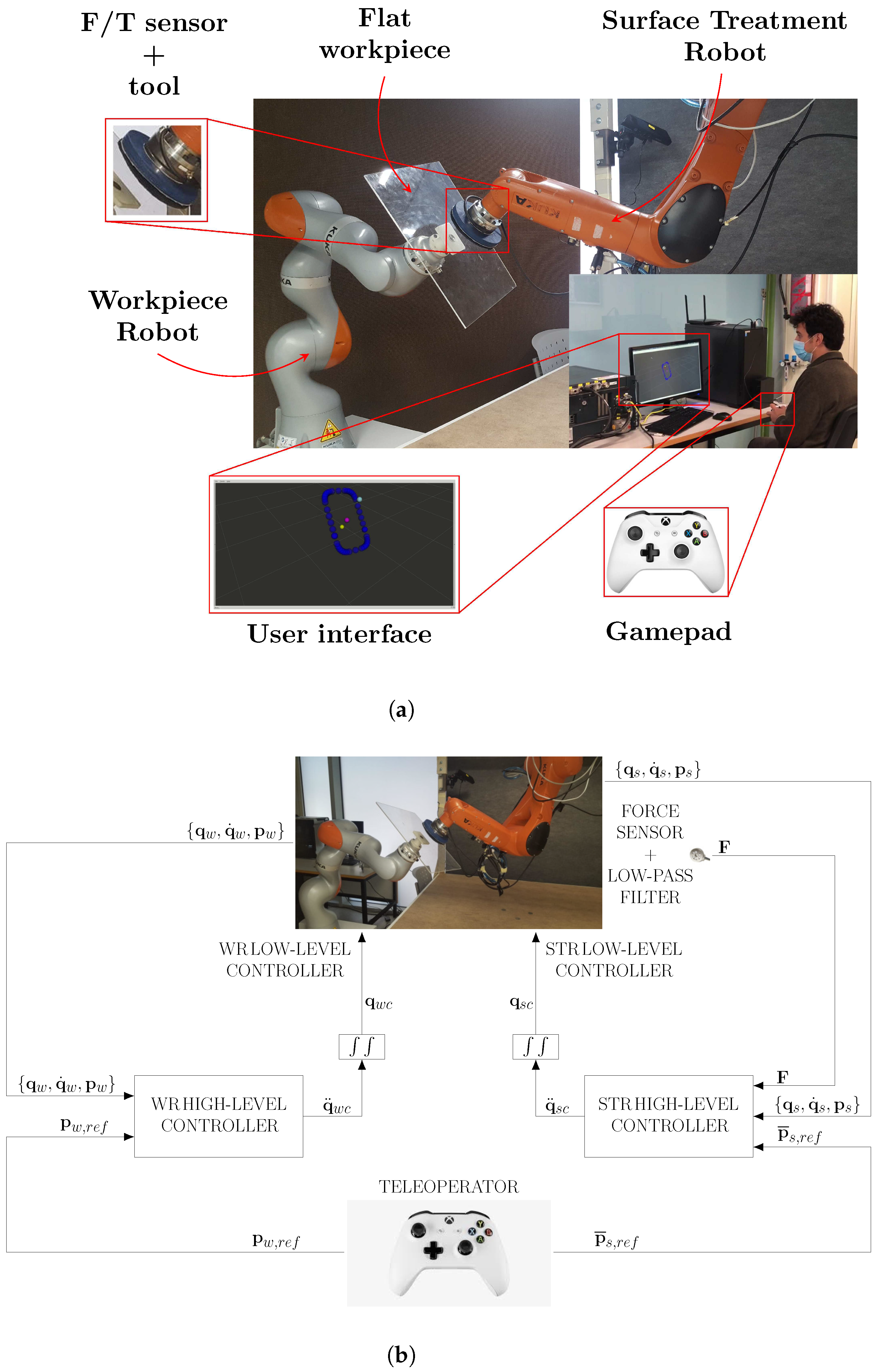
The advanced bimanual robot teleoperation is based on the task-priority strategy [71,72] and conventional and non-conventional Sliding Mode Controllers (SMCs) [73,74]. As commented before, the goal of this bimanual robotic application is to perform a human–robot cooperative control loop so that the user operator partially teleoperates two robotic arms to perform a surface treatment operation, whilst the robots automatically ensure the appropriate tool force and orientation; see Figure 1. Thus, the so-called workpiece robot (WR), which consists of a 7R collaborative robot with a workpiece of flat methacrylate fixed to the end-effector using a self-made piece (see Figure 1a), is in charge of holding the workpiece. Meanwhile, the so-called surface treatment robot (STR), which consists of a 6R robotic arm with a Force/Torque (F/T) sensor and a cylinder-shaped tool with a piece of cloth (see Figure 1a), operates with the surface treatment tool on the workpiece. Thus, the user controls the workpiece position and orientation and, simultaneously, controls the 2D tool motion on the workpiece surface using an interface, which consists of a gamepad to command the robots and a visual feedback screen to show the user the robots and the user reference states; see Figure 1a.
Figure 1b shows the block control diagram for both robots, where subscript s stands for the STR; subscript w stands for the WR; subscript ref stands for the user reference; subscript c stands for the commanded control action; is the robot pose, i.e., the linear positions plus orientation angles ; is the 2D position of the STR tool on the workpiece surface, i.e., the linear positions relative to this surface; is the robot configuration, with n the number of robot joints; and is the vector containing the measured forces and torques. Thus, using the gamepad joysticks, the user is able to send the reference to the WR pose and, simultaneously, the reference to the 2D position of the STR tool on the workpiece surface. Thus, the high-level controllers of both robots compute the corresponding joint commands from the user references, the state of both robots, and the force sensor data . These joint commands are then sent to the low-level controllers of both robots, as shown in Figure 1b, in order to complete the teleoperation task. See [31] for further details on the high-level controllers of both robots and the related signals.
In addition, some constraints are considered for both robots in order to increase the safety of the task: (1) the WR is automatically controlled to maintain the workpiece center inside the allowed region that is modeled as a superellipsoid, which is similar to a rectangular prism with smooth corners; (2) the STR is automatically controlled to keep the center of the treatment tool within the allowed region on the workpiece, which is modeled as a superellipse, i.e., a rectangle with smooth edges.
2.2. Description of the Controllers
The control architecture developed in [31] for each robotic manipulator of the application is as follows.
The control of the WR is given by 4 prioritized tasks:
- (W1)
- The highest-priority task is used to keep the workpiece center inside the aforementioned superellipsoid and is accomplished using non-conventional SMC.
- (W2)
- The medium–high-priority task is used to keep the angular position of the workpiece within a certain range and is accomplished using non-conventional SMC.
- (W3)
- The medium–low-priority task is used to allow the user to command the WR and is accomplished using a hybrid SMC.
- (W4)
- The lowest-priority task is utilized to “push” the WR configuration towards a home (only applies for a redundant WR).
The control of the STR is given by 3 prioritized tasks:
- (S1)
- The highest-priority task is used to keep the center of the treatment tool within the aforementioned modified superellipse and is accomplished using non-conventional SMC.
- (S2)
- The medium-priority task is used to exert the appropriate pressure with the tool on the workpiece, as well as to maintain the orientation of the tool perpendicular to the surface of the workpiece. It is accomplished using conventional SMC.
- (S3)
- The lowest-priority task is used to allow the user to command the STR and is accomplished using a hybrid SMC.
2.3. Description of the Conventional PC-Based Interface
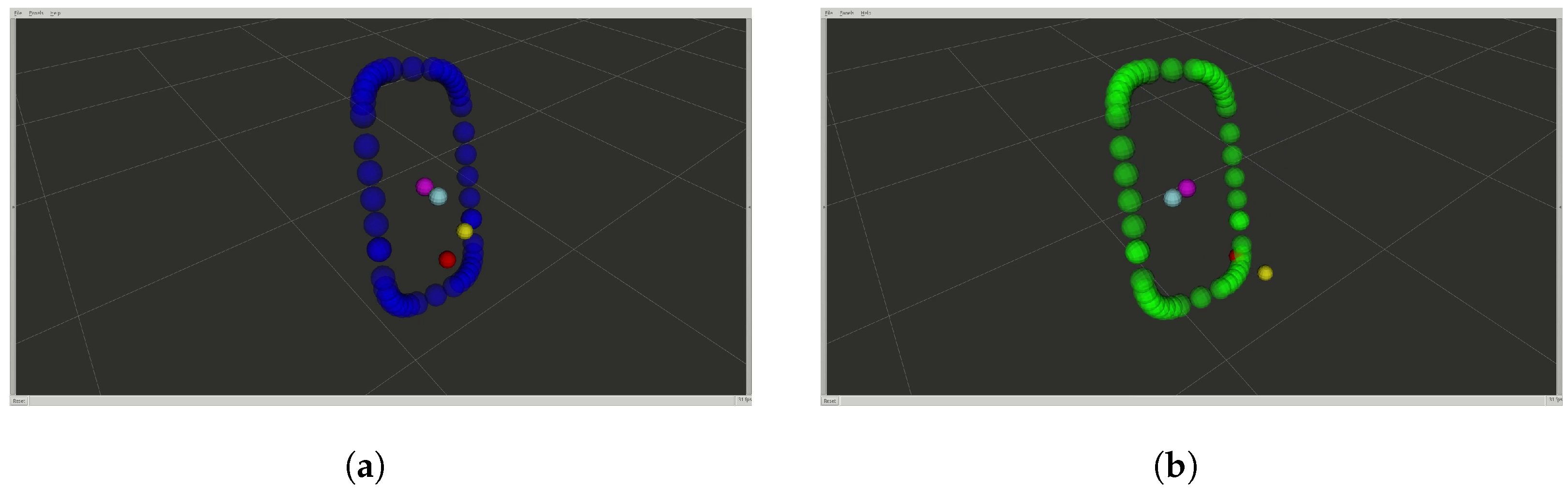
The authors in [31] proposed a conventional PC-based interface, which shows a 3D interface on a screen, that is composed of the following visual elements (see Figure 2):
- -
- STR reference consisting of a yellow sphere. The position of this element is controlled by the user using the gamepad input.
- -
- STR current tool position consisting of a red sphere.
- -
- STR boundary and WR workpiece orientation consisting of several blue spheres positioned along the curved define by the modified superellipse. When the tool collides with the boundary, the color of these spheres changes from blue to green.
- -
- WR reference consisting of a cyan sphere. The position of this element is controlled by the user using the gamepad input.
- -
- WR current workpiece position consisting of a pink sphere.
Note that the user commands both robots by means of the gamepad.
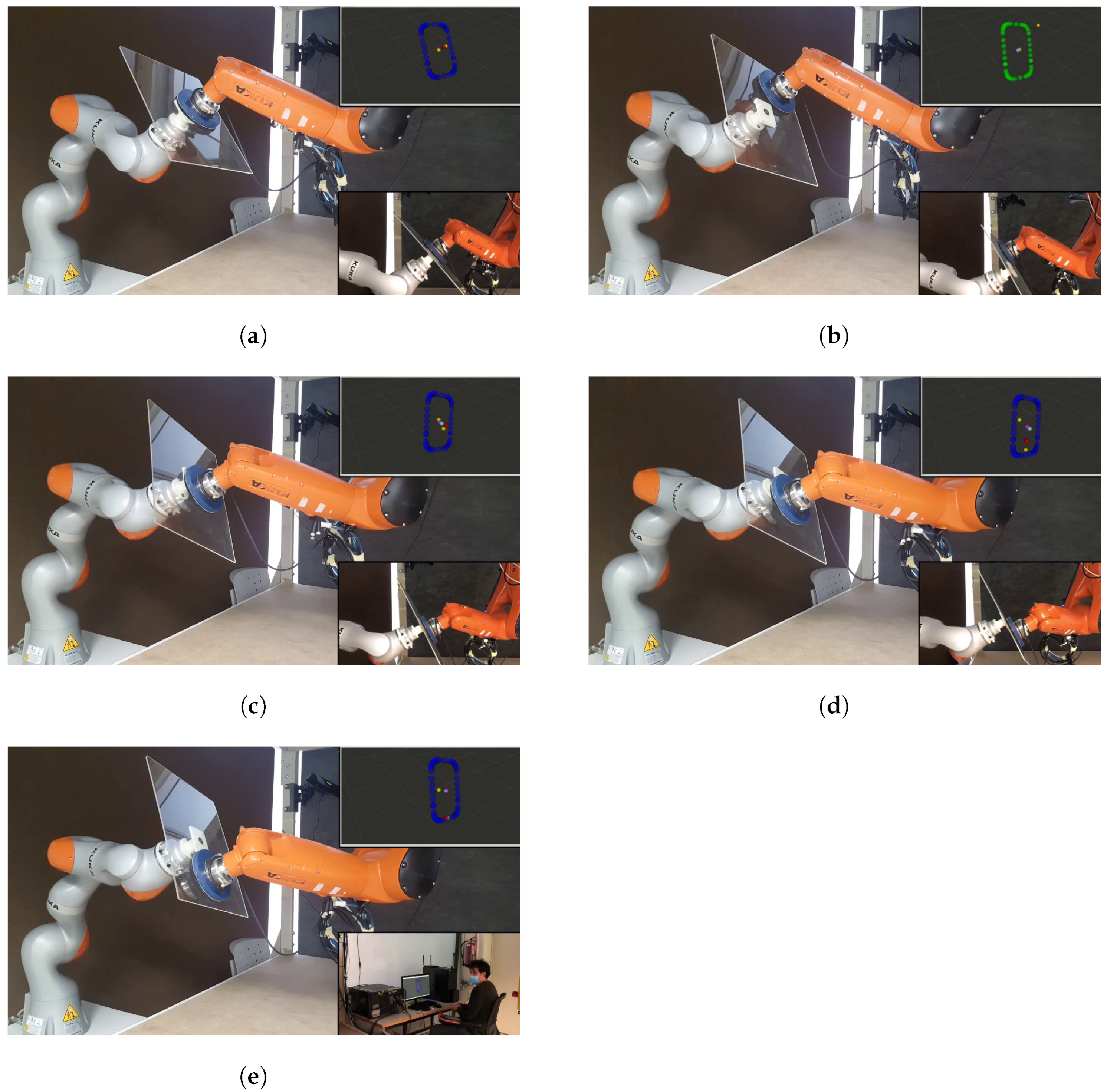
Figure 3 shows several frames for the performance of the described application, focusing on the interface; see the video at https://media.upv.es/player/?id=15ffabe0-a733-11eb-a0b0-2fbcb59aaef7 (accessed on 26 April 2022) [75].
2.4. Discussion of Human–Robot Interaction Using Conventional Interfaces
The conventional PC-based user interface presents several problems that directly affect the task performance. Next, the three most relevant problems, which were identified from questions asked to several users that tested the application described above, are discussed.
The first significant problem reported by the users is that their interaction with the virtual environment was not natural. In particular, the robotic system is teleoperated in the 3D space and, hence, it requires changing the screen view to properly track the task. To do this, the user has to stop the robot teleoperation and accommodate the interface, affecting the total amount of time needed to complete the task.
The second significant problem reported by the users is that it was difficult for them to see the real system at any time. In this sense, Figure 3e shows the user looking at the real system instead of the interface while performing the task. The reason given by several users, who exhibited the same behavior, was that they needed to see what the real system was doing because they did not know if the task was being done correctly or not. This means that this type of interface does not properly help the user to conduct the real task.
The third significant problem reported by several users is that it was difficult for them to move the references in the virtual 3D space, wasting a lot of time before resuming the robotic task.
All these issues and problems show the difficulties of using conventional interfaces and make evident the need to develop new interfaces allowing a more intuitive user interaction, especially when working with complex systems such as the bimanual robotic system considered in this work.
3. Proposed Augmented Reality-Based User Interface
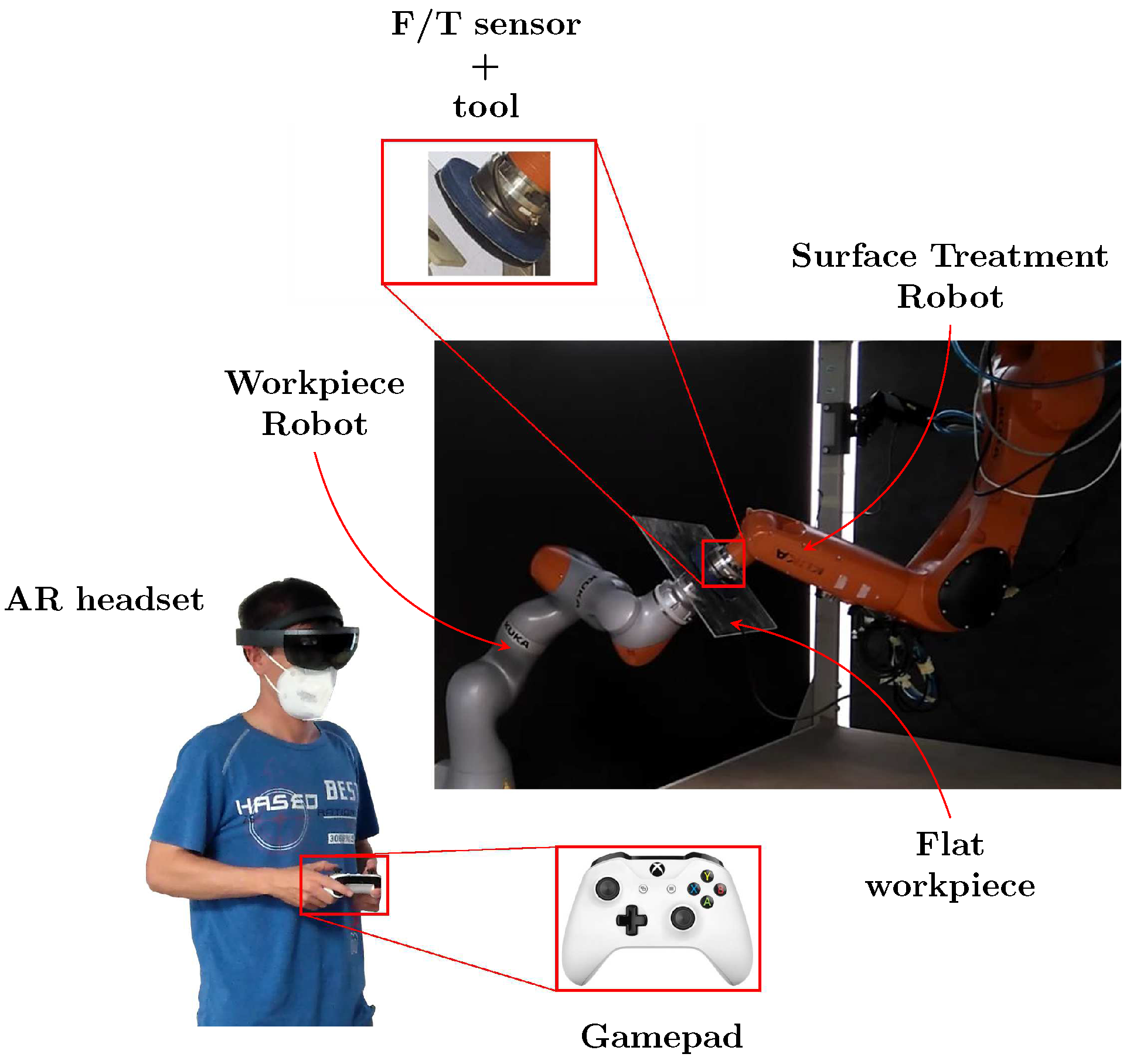
In order to overcome the aforementioned problems of the conventional PC-based interface, this work proposes the use of AR technology to improve the user ergonomics and task performance. In particular, the conventional PC-based interface used in the previous setup (see Figure 1a) is replaced by an AR headset in the new setup—see Figure 4—allowing the user to see the relevant information in the form of holograms while still seeing at all times the real elements involved in the task: robots, workpiece, tool, etc. Note that the remaining elements of the new setup (see Figure 4) are the same as in the previous setup (see Figure 1a): an STR with an F/T sensor and a cylinder-shaped tool with a piece of cloth; a WR with a flat workpiece of methacrylate attached to the end-effector using a self-made piece; and a gamepad to command both robots.
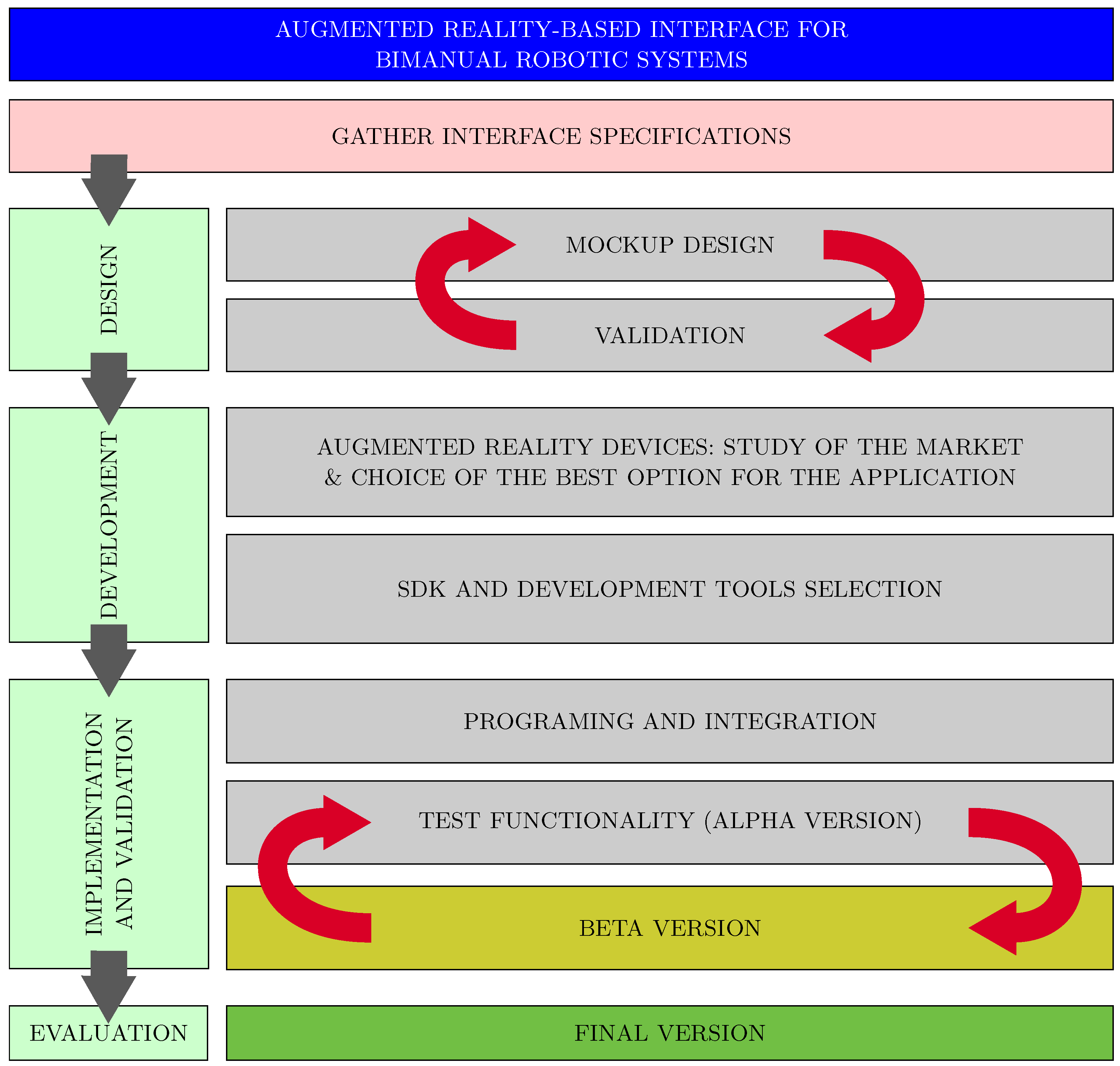
Figure 5 shows the methodology considered in this work to develop and validate the proposed AR-based interface. Although this methodology is used below to design the AR interface for the specific bimanual robot teleoperation task at hand, it is generic and, in general, it can be applied to design AR interfaces for other types of applications.
Firstly, the requirements of the applications were established based on the opinions of several users who previously tested the conventional PC-based interface. These requirements are summarized in Table 1.
A mockup design was developed taking into account this information. The designed AR-based interface has, from a functionality perspective, two kinds of virtual objects: firstly, those representing the STR and WR reference indicators; and, secondly, those corresponding to the boundaries information. In order to develop both kinds of virtual objects, several tools and strategies related to the mockup design were used. These preliminary designs were validated by some users before their implementation.
Once the preliminary design was finished, the following step was to study the best option of AR headset to be used for the application at hand. Several considerations were taken into account, especially the following: first, the capability of the device to be used in industrial environments; second, the stability of the holograms, which is important when working in this kind of application; third, the computational power of the device; fourth, the sound capabilities; and fifth, the communication capability (i.e., Bluetooth and WiFi). Note that most AR headsets in the market accomplish the aforementioned requirements. However, among all of them, Microsoft HoloLens glasses [76] were chosen because the second generation of this device offers several services that could be added to the final version of the interface according to the company needs [77].
Once the AR headset was selected, the interface was developed. Using a PC workstation, the proposed virtual objects were created and assembled in a virtual space using Blender 2.7 [78] and Unity [79], respectively. This was an iterative design process, where the main characteristics of the virtual objects (e.g., size, color, shape, etc.) and their interactions were verified and modified, connecting the workstation with the AR headset in a remote mode from the Unity editor (note that the perception of the holograms is different when showing them in a PC screen compared to when projecting them in the real world through the AR headset), until the result was satisfactory.
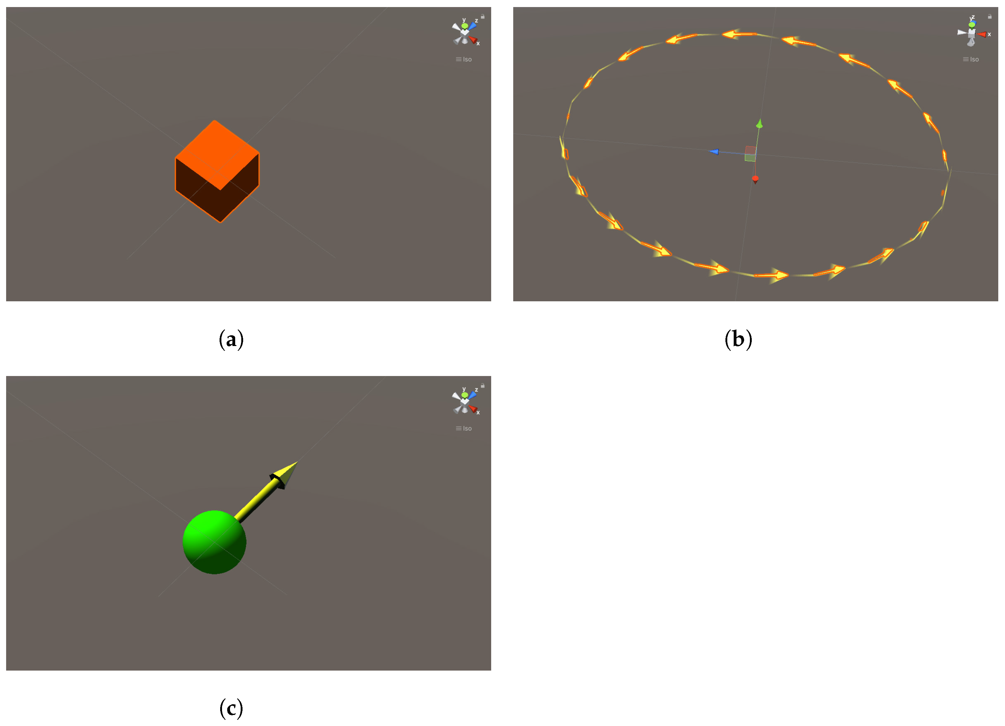
Figure 6 shows the holograms designed for the robot references. In the case of the WR, the user can command the robot through the 3D workspace and modify the end-effector orientation. For this reason, two different holograms were designed. The translation reference hologram was modeled by a 3D orange cube; see Figure 6a. This hologram appears when the user teleoperates the WR translation reference. To reduce the number of holograms present at any moment, this hologram disappears 3 s after the user has stopped moving the WR translation reference. The orientation reference hologram was modeled by an animated arrowed yellow circle; see Figure 6b. This hologram appears when the user teleoperates the WR rotation reference, and disappears 3 s after the user has stopped moving the WR rotation reference. It should be noted that, in both cases, the movement of the references is relative to the position of the user, i.e., the AR headset, making their use more intuitive and natural. The STR translation reference was modeled by a yellow arrow attached to a green sphere; see Figure 6b. Note that this hologram is constrained to the plane of the workpiece surface, allowing a 2D movement. This hologram disappears 3 s after the user has stopped moving the STR translation reference.
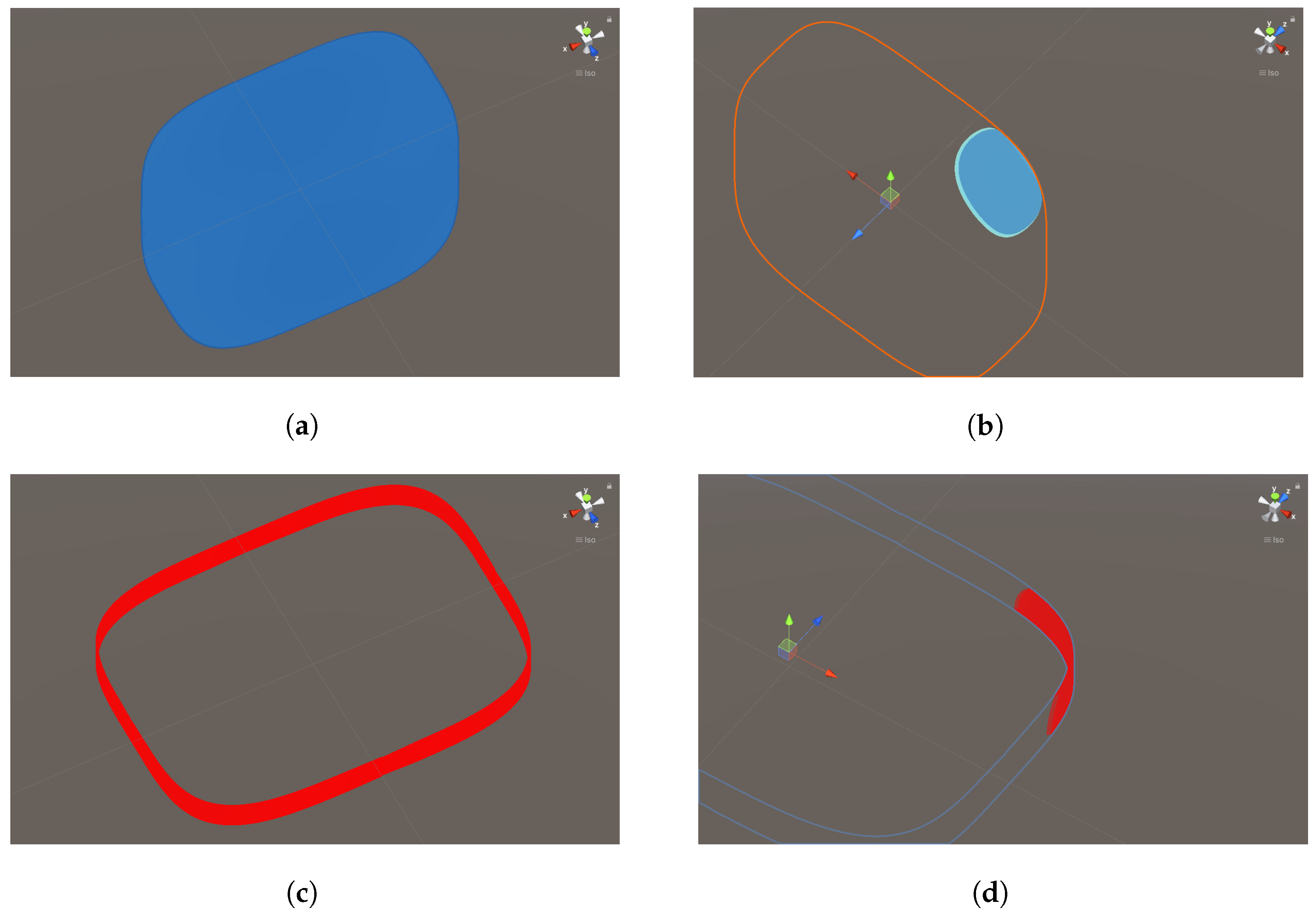
Figure 7 shows the holograms designed for the 2D and 3D boundaries.
The 3D boundary is modeled by a superellipsoid—see Figure 7a—which is defined as:
where are the superellipsoid axes and m represents the smoothing parameter of the superellipsoid, i.e., it is equivalent to an ellipsoid for , whereas it tends to a cuboid as m tends to infinity. For the bimanual robot application at hand, it has been chosen .
The 2D boundary is modeled by a modified superellipse—see Figure 7c—which is defined as:
where it is implicitly assumed that the value of axis H is greater than that of axis W (the expression is easily modified for the analogous case ). This equation represents a rectangle with smooth corners, with for its long side and for its short side, by joining a rectangle to two offset halves of an even-sided superellipse.
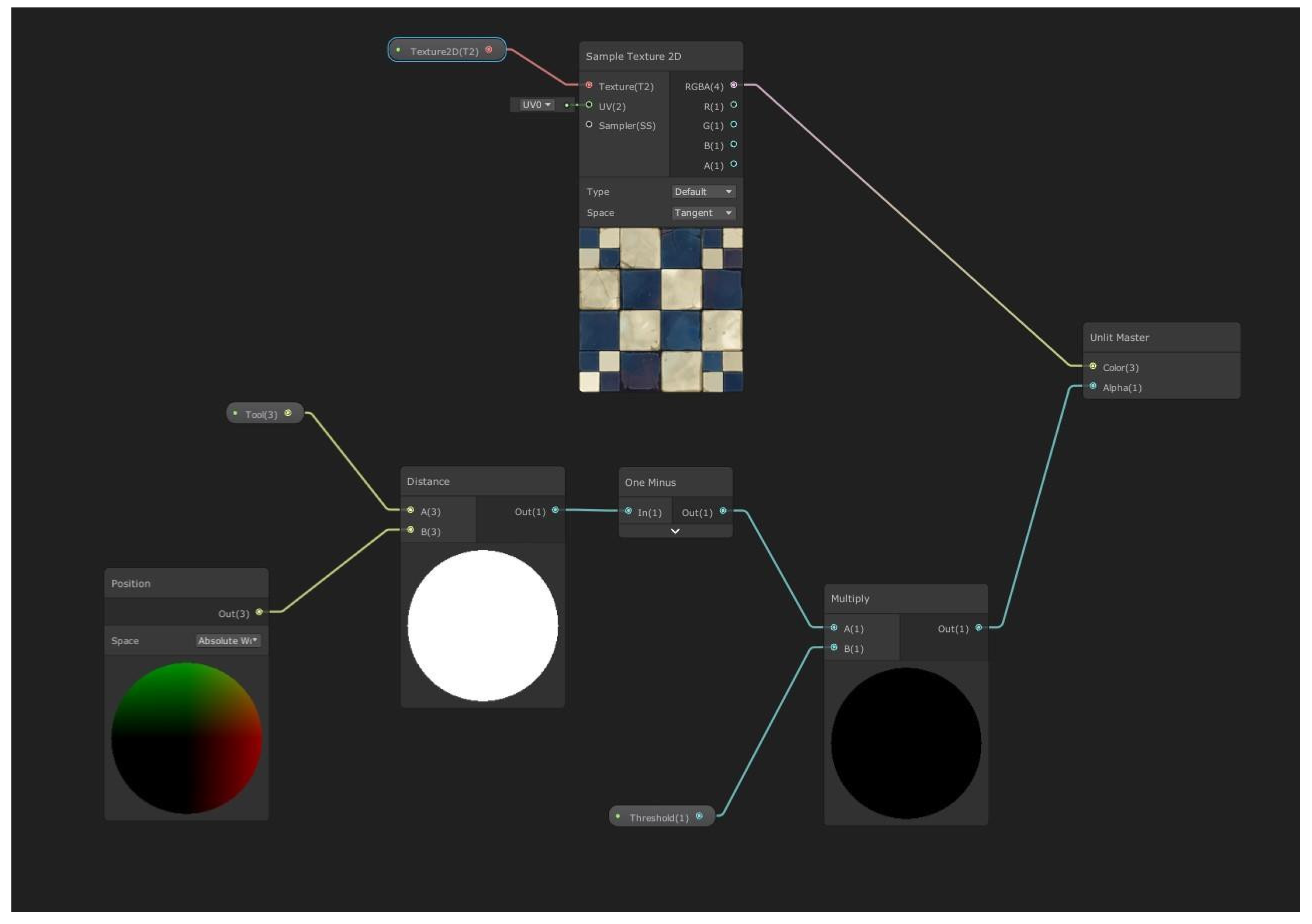
Note that if the proposed boundary holograms were permanently shown, they could occlude some real elements from the user’s view, affecting the task performance. For this reason, a new material shader [80] was designed; see Figure 8. This shader computes the minimum distance between the robot end-effector and the 3D boundary, for the case of the WR, or the closest point of the robot tool to the 2D boundary, for the case of the STR. Thus, the shader only displays the affected part of the boundary hologram. That is, as the WR end-effector and/or the STR tool approach to the 3D and 2D boundaries, respectively, the part of the boundary hologram affected is progressively displayed; see Figure 7b,d.
In addition to this, and according to the user requirements, two warning sounds were included in the interface: the first one to indicate that the STR tool is close to the 2D boundary; and the second one to indicate that the WR end-effector is close to the 3D boundary. Moreover, the user is able to deactivate this warning sound at any time.
Once the main holograms and sound elements were implemented, some communication protocols were used and programmed. Bluetooth communication between the Microsoft HoloLens glasses and the gamepad was established to allow the user to provide commands to the interface. Moreover, in order to avoid non-desired interactions with the interface, voice and gesture commands were deactivated by default. In addition, the AR interface and the robot controller communicate via WiFi with Protocol TCP/UDP at 10 Hz.
4. Results
This section presents four experiments to show the main functionalities of the developed AR-based interface; the performance of the 2D boundary and the STR reference hologram; the performance of the 3D boundary and the WR reference hologram; and the performance of the overall system when the user commands simultaneously both robots using the proposed AR-based interface.
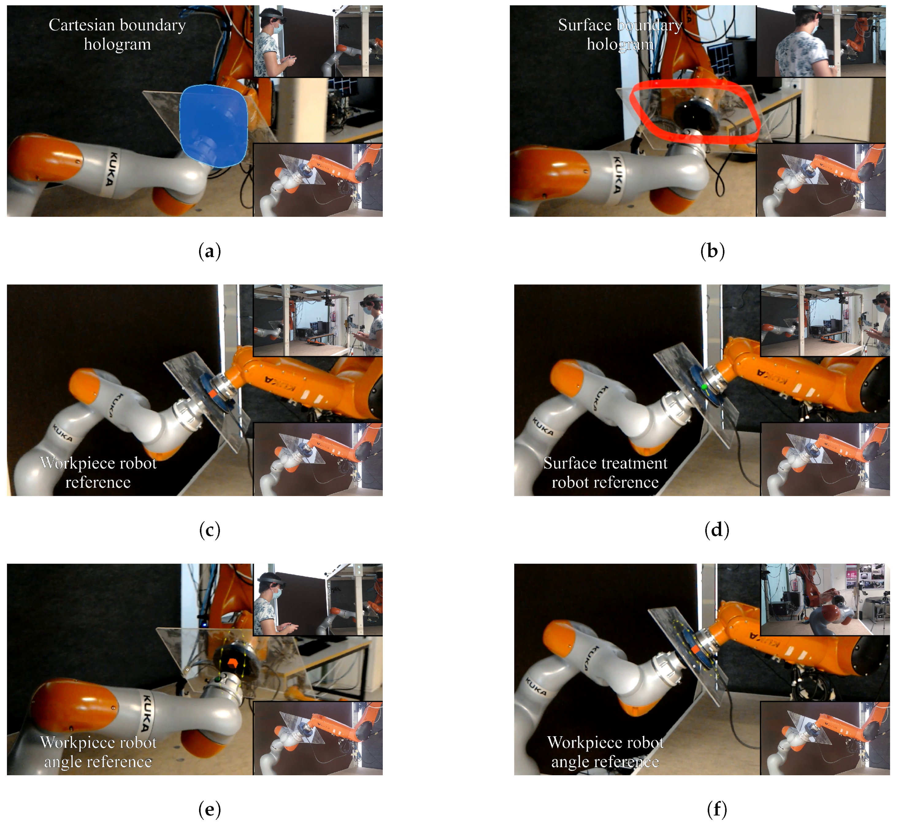
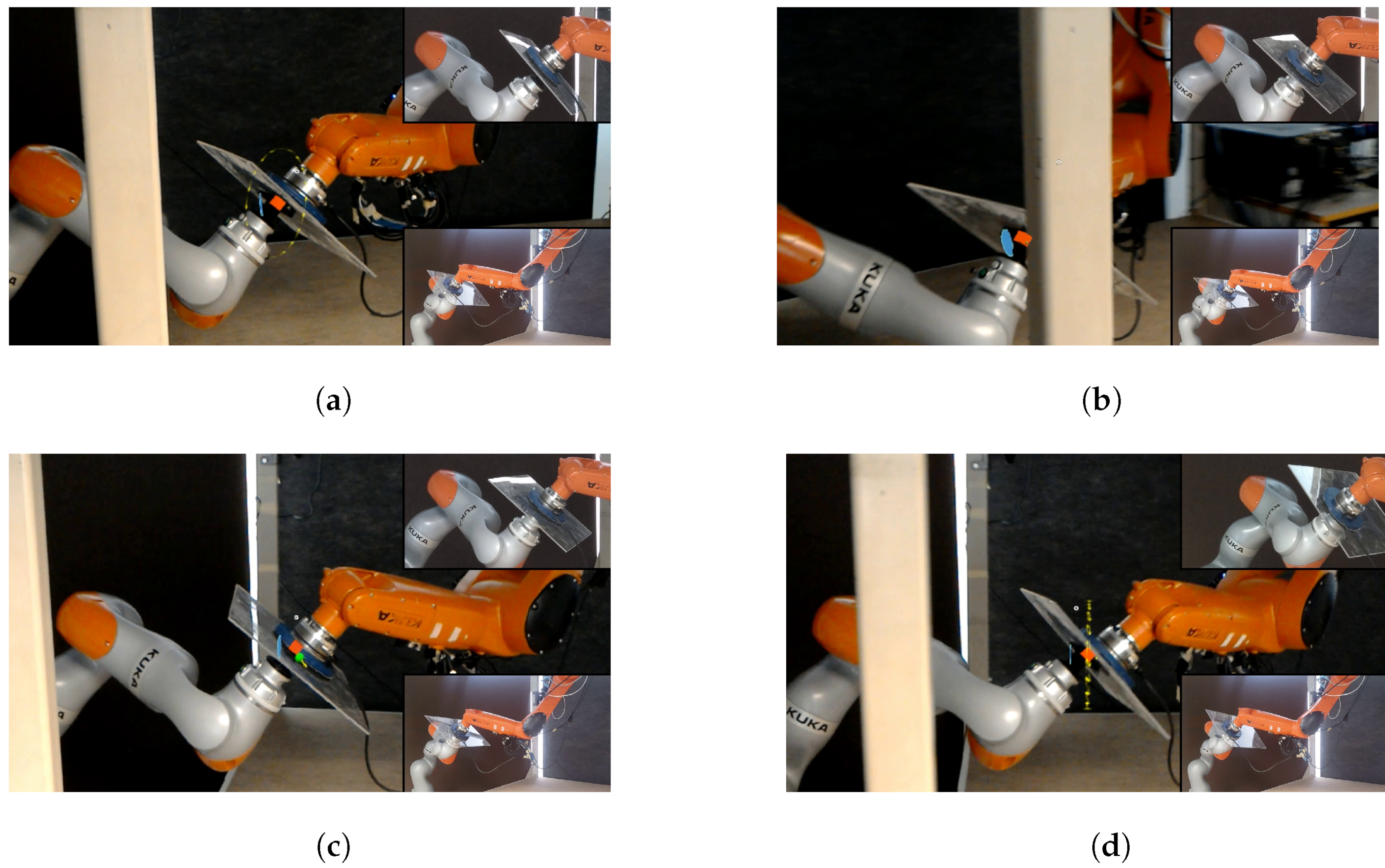
Figure 9 depicts several frames of the first experiment, which shows the main functionalities of the AR interface implemented in the Microsoft HoloLens glasses; see the video at https://media.upv.es/player/?id=a64014f0-8a5a-11ec-ac0a-b3aa330d3dad (accessed on 26 April 2022) [81]. Figure 9a shows the full 3D boundary hologram, whilst Figure 9b shows the full 2D boundary hologram. Note that both holograms are hidden by default. Figure 9c shows the WR end-effector translation reference hologram, whilst Figure 9e,f show the WR end-effector rotation reference hologram. Note that, in the case of the rotation, the animated arrows indicate the direction of the commanded angle while the yellow circle indicates the rotation in the roll, pitch, and yaw angles, or a combination of them. Figure 9d shows the STR reference hologram.
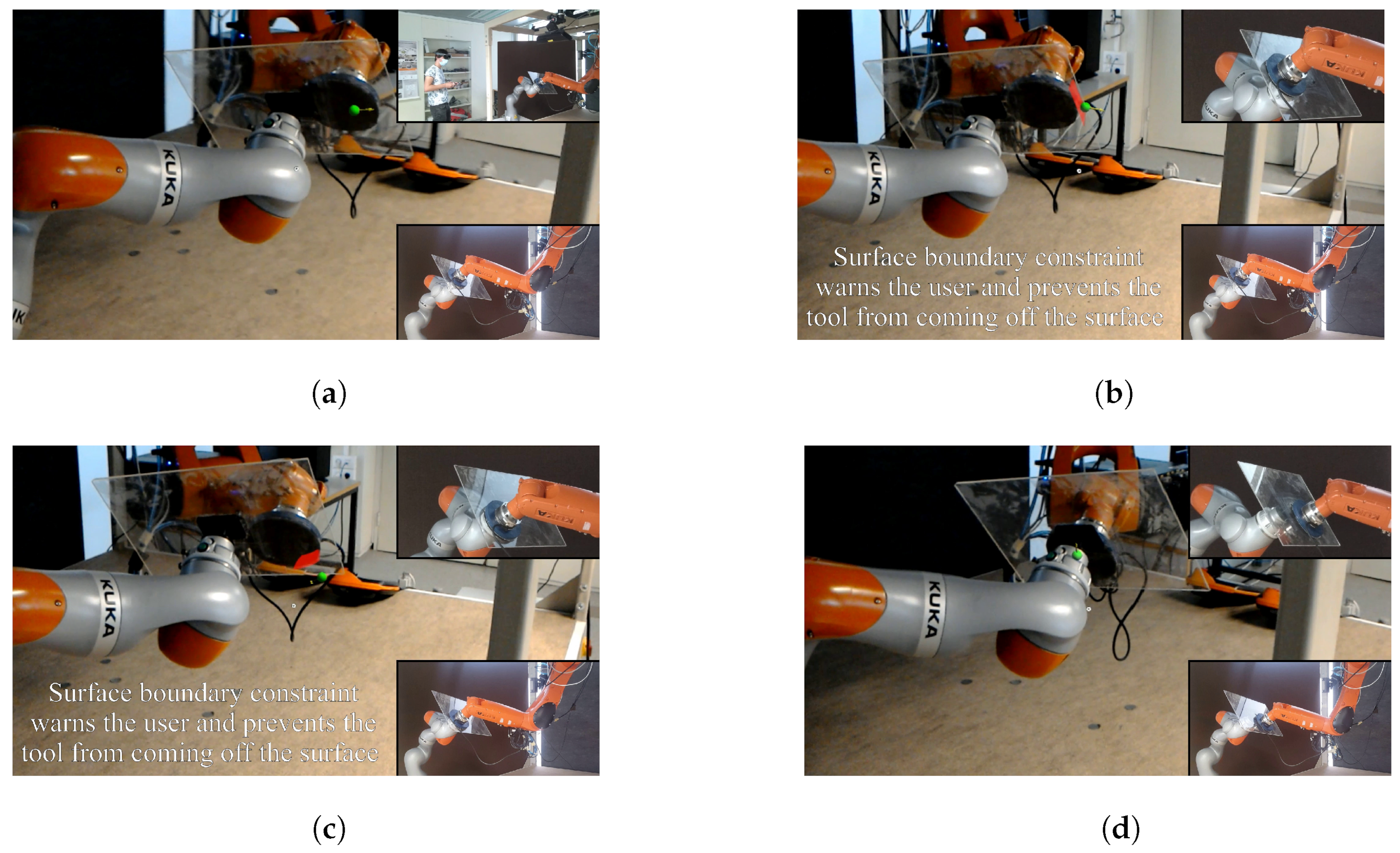
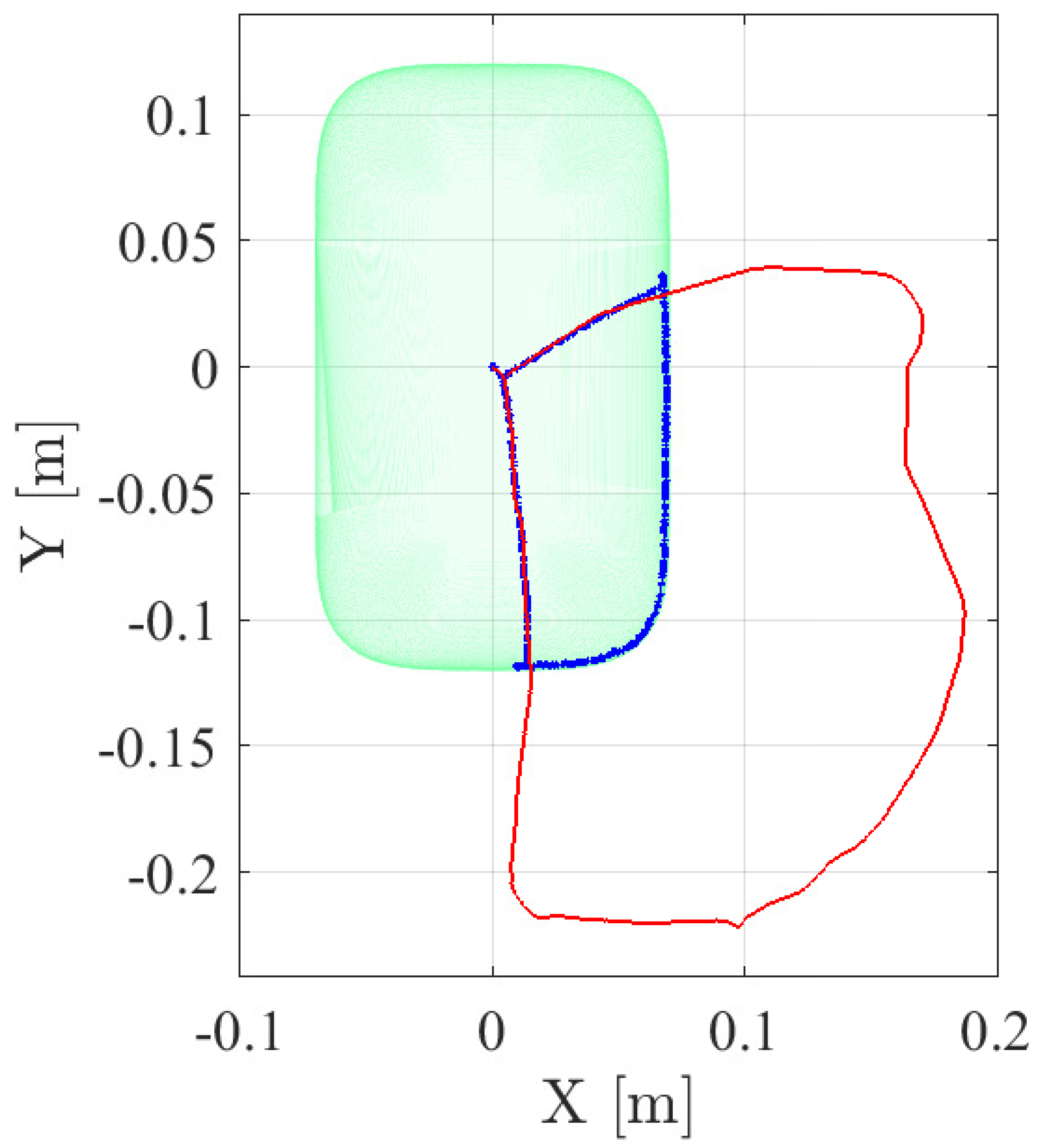
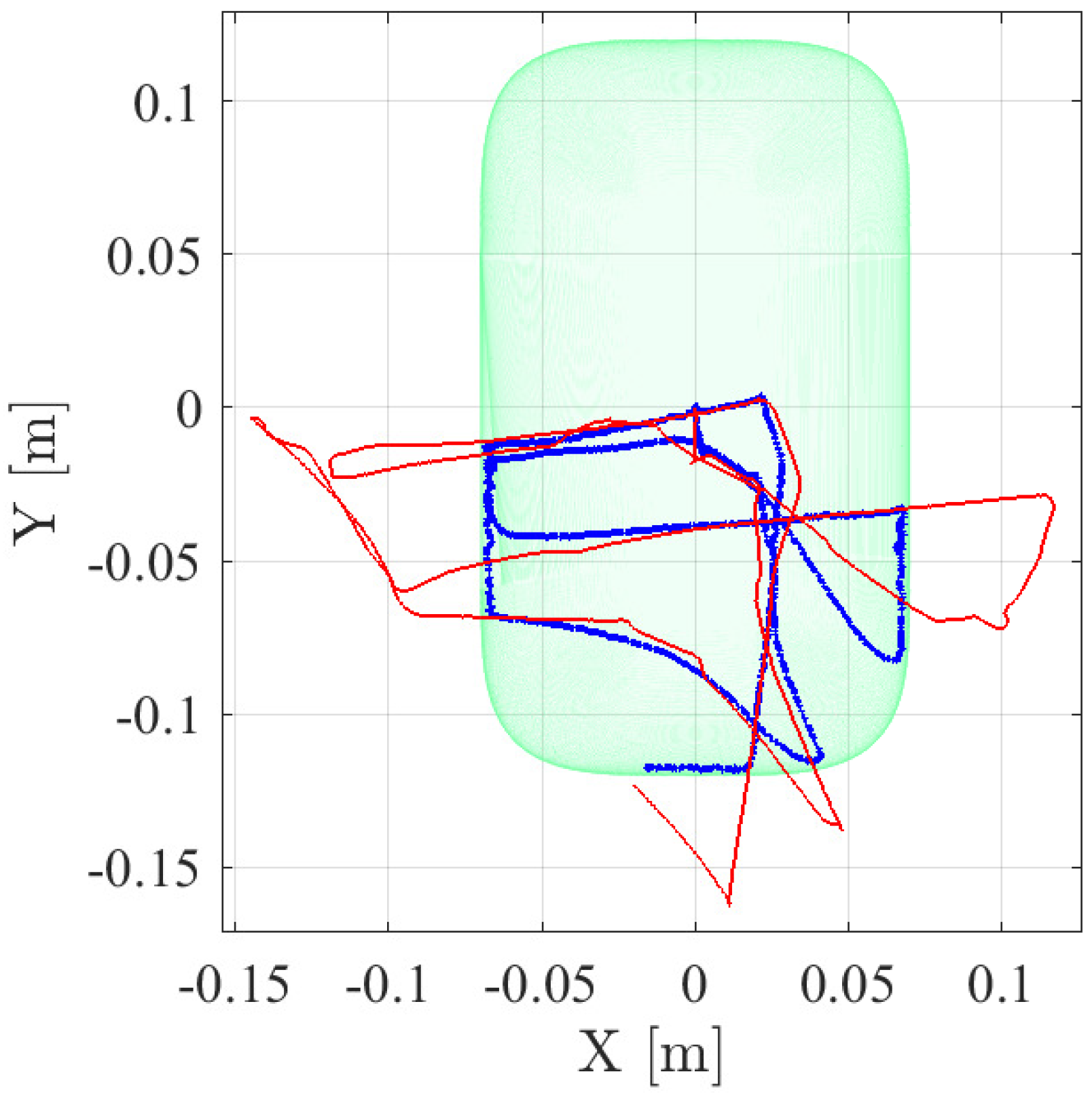
Figure 10 depicts several frames of the second experiment, which shows the performance of the 2D boundary and the STR reference hologram; see the video at https://media.upv.es/player/?id=9504e6f0-8a61-11ec-b7c7-7d27dda7c5d5 (accessed on 26 April 2022) [82]. Figure 10a shows how the user is commanding the STR tool towards one side of the workpiece and, when the tool approaches the 2D boundary, the boundary region closest to the STR tool is shown in red and the warning sound is activated; see Figure 10b,c. Note that, when the user reference exceeds the 2D boundary, the tool is automatically kept within the allowed region. More details about this aspect can be further analyzed in Figure 11, which shows the allowed region on the workpiece surface, the trajectory followed by the user reference, and the trajectory followed by the STR tool. Figure 10d shows how the 2D boundary hologram automatically disappears when the STR tool is far from the 2D boundary.
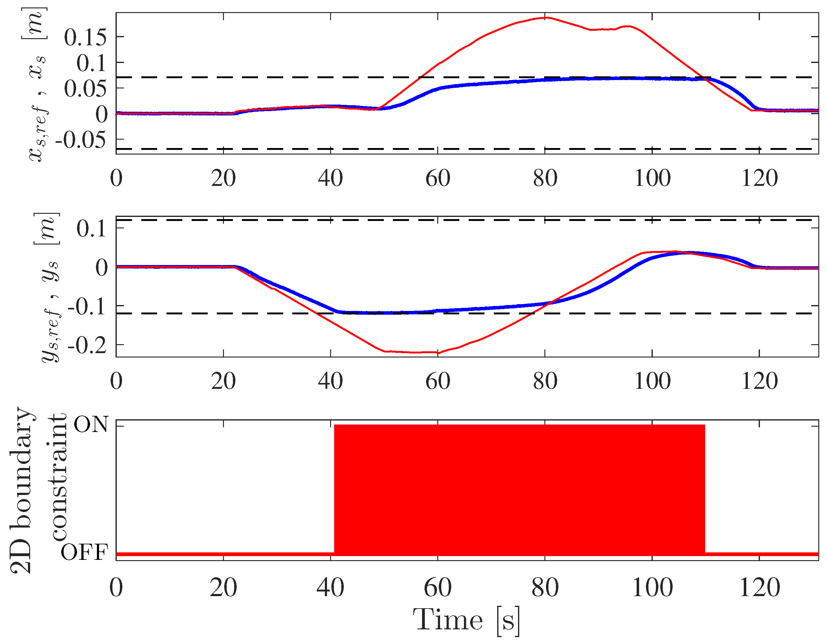
Figure 12 shows the position followed by the STR tool on the workpiece surface, which is due to the STR teleoperation, together with the reference values provided by the user. In particular, it can be appreciated that the trajectory described by the STR tool corresponds closely to the user reference values, except obviously when the 2D boundary constraint is active; see the bottom graph in Figure 12. In fact, the maximum deviation of the actual STR position values compared to the user reference values, when the 2D boundary constraint was not active, was around cm, with a standard deviation of around cm; see Table 2. Note that these teleoperation error values include all the potential sources of error: communication delays, high-level and low-level robot control, the accuracy of the workpiece location, teleoperation system, etc. Therefore, it can be concluded that the accuracy of the proposed AR-based teleoperation of the STR is sufficient for the task at hand.
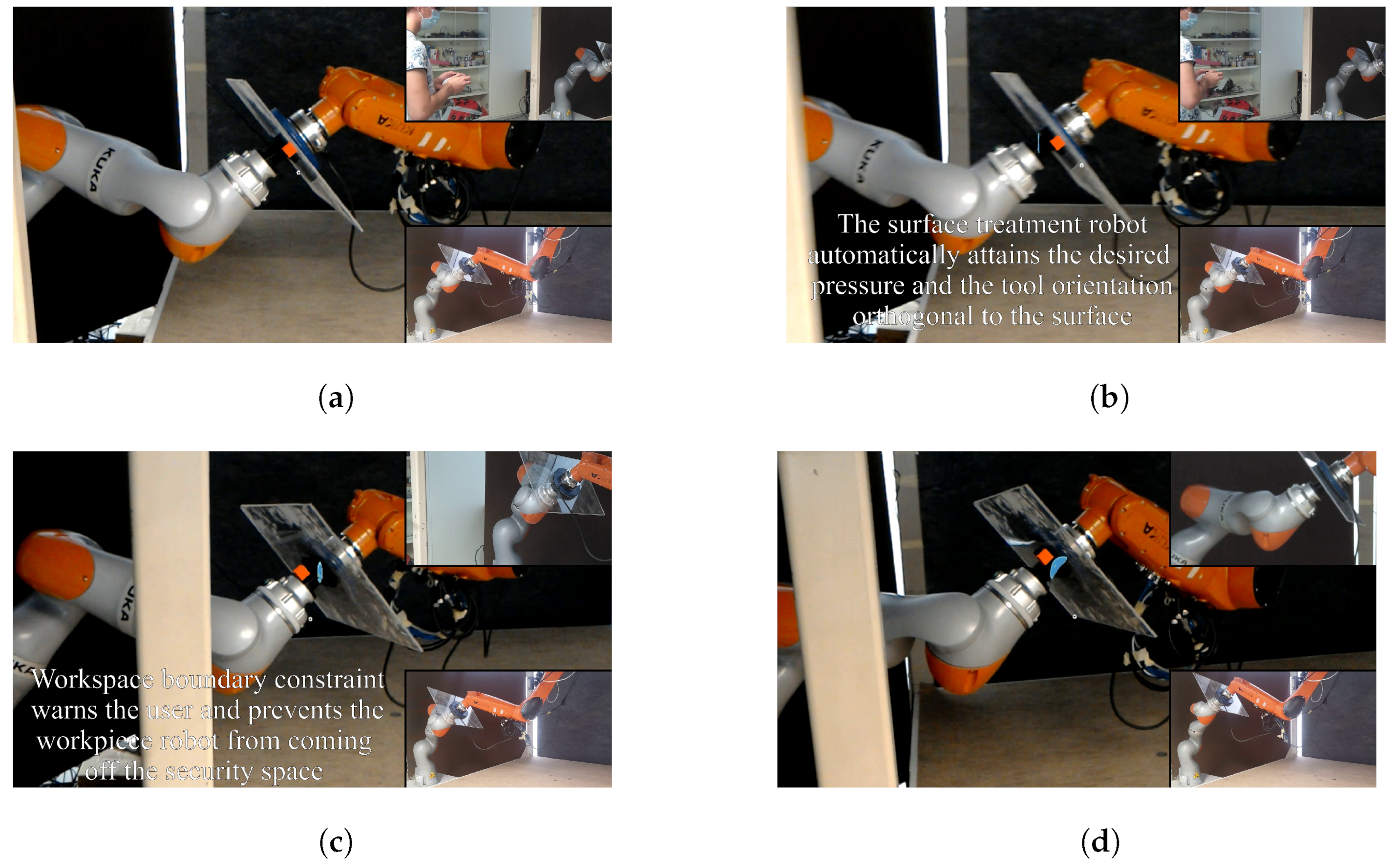
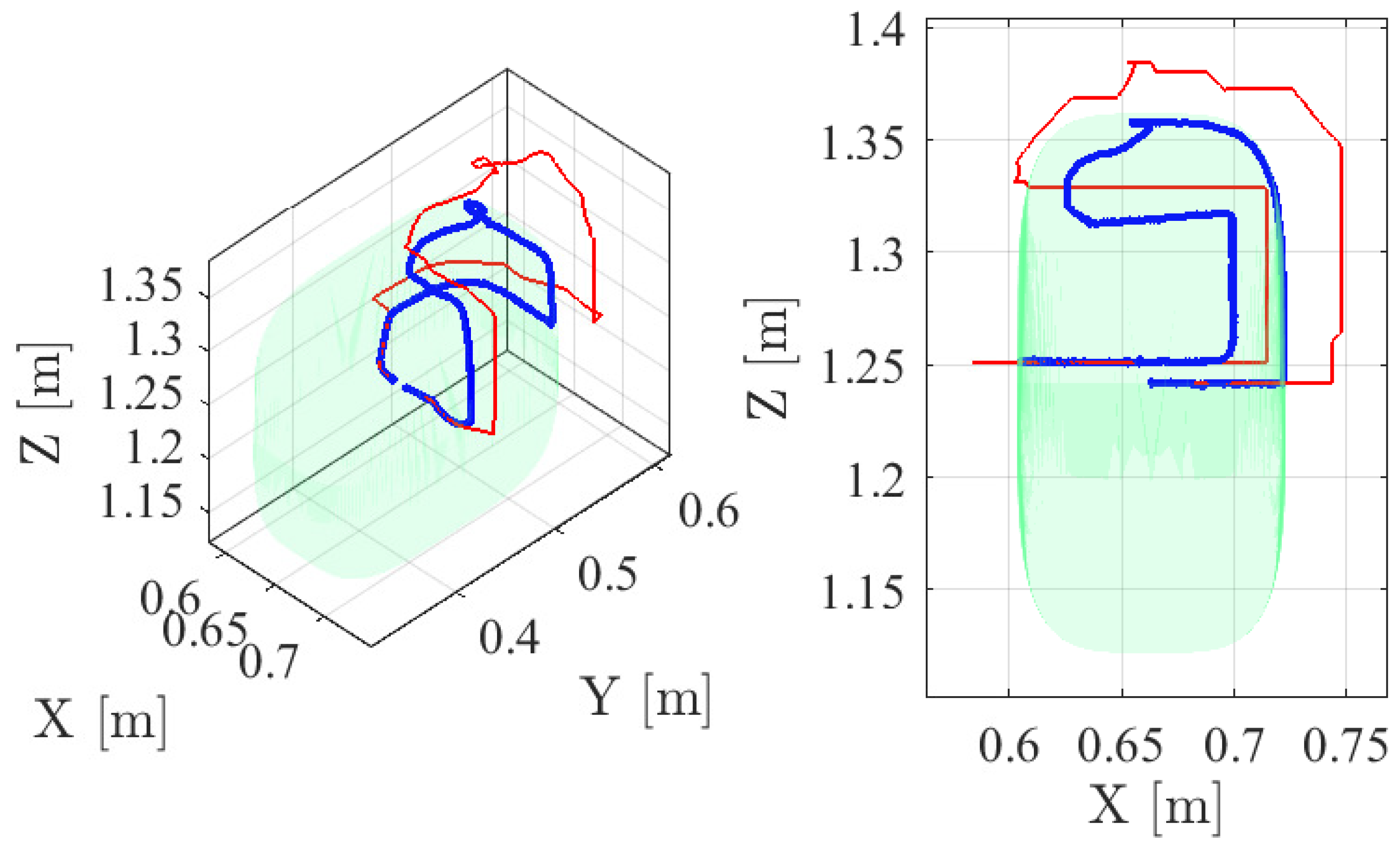
Figure 13 shows several frames of the third experiment, which shows the performance of the 3D boundary and the WR reference hologram; see the video at https://media.upv.es/player/?id=17d88200-8f0b-11ec-be22-d786eca82090 (accessed on 26 April 2022) [83]. Figure 13a shows how the user is commanding the WR and, when the WR end-effector approaches the 3D boundary, the boundary region closest to the WR end-effector is shown in blue and the warning sound is activated; see Figure 13b–d. Note that, when the user reference exceeds the 3D boundary, the WR end-effector is automatically kept within the allowed region. More details about this aspect can be further analyzed in Figure 14, which shows the allowed 3D region, the trajectory followed by the user reference, and the trajectory followed by the WR end-effector.
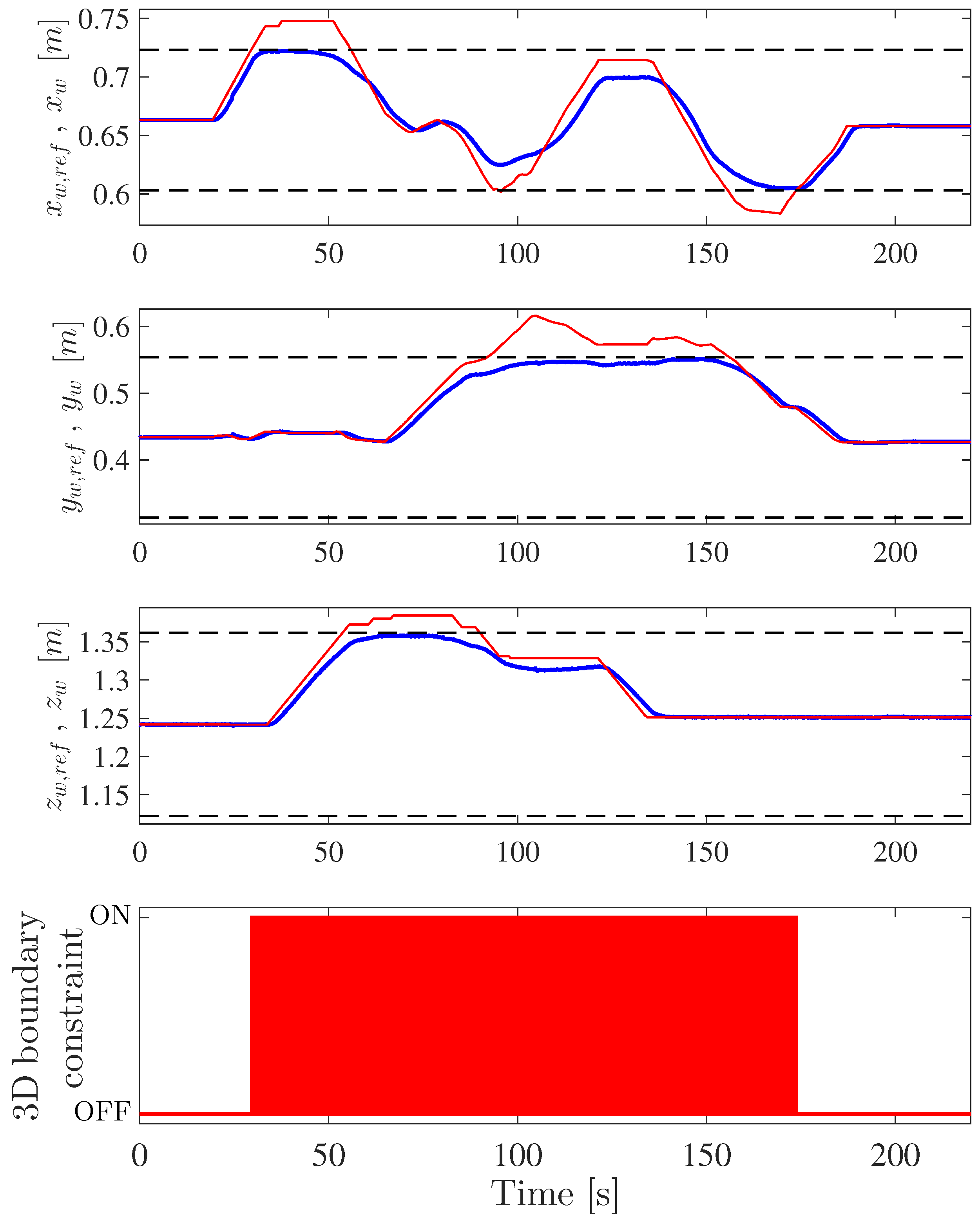
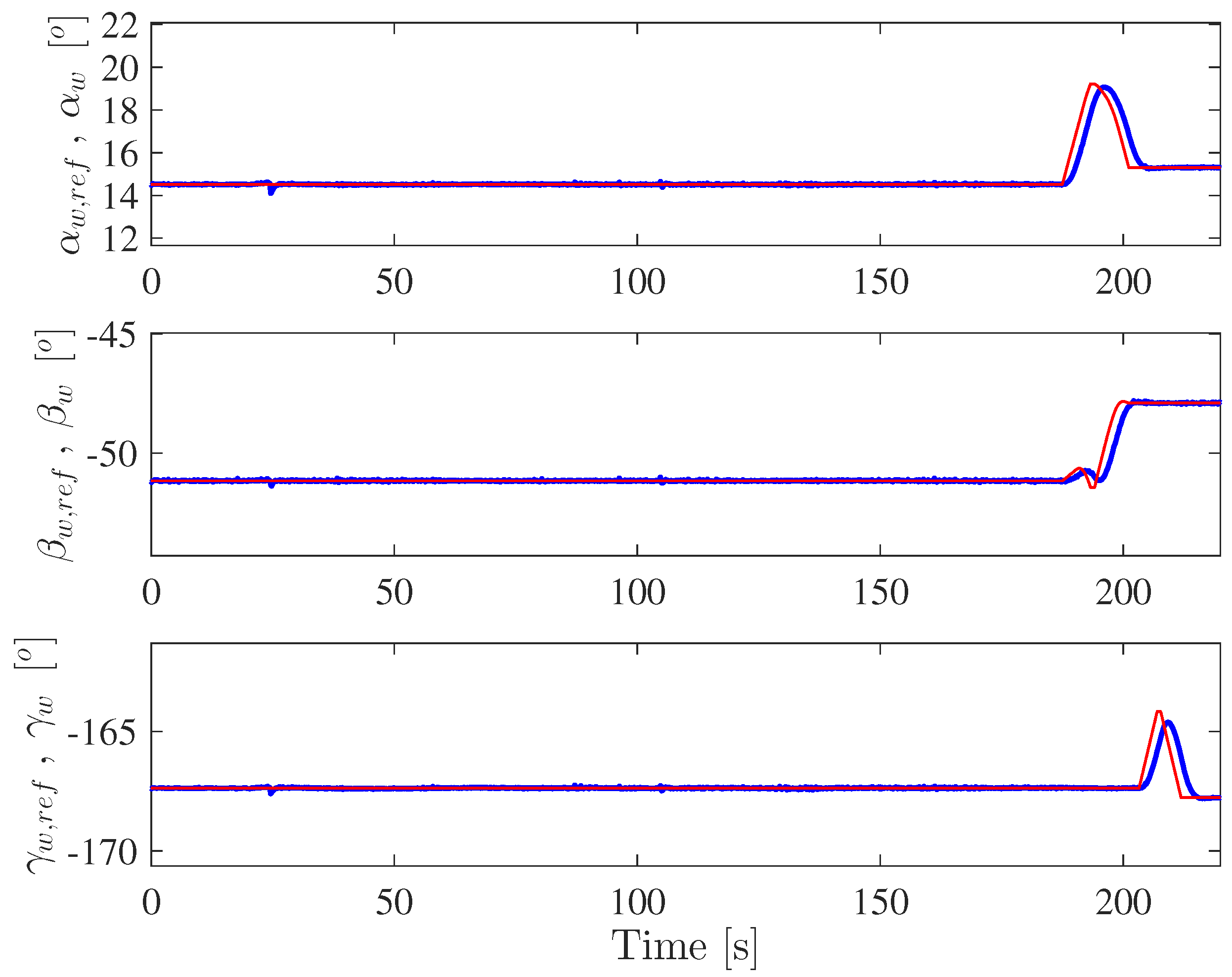
Figure 15 and Figure 16 show the position and orientation, respectively, followed by the workpiece, which are due to the WR teleoperation, together with the reference values provided by the user. In particular, it can be appreciated that the trajectory described by the workpiece corresponds closely to the user reference values, except obviously when the 3D boundary constraint is active; see the bottom graph in Figure 15. In fact, the maximum deviation of the actual workpiece position values compared to the user reference values, when the 3D boundary constraint was not active, was around cm, with a standard deviation of around cm; see Table 3. Moreover, the maximum deviation of the actual workpiece orientation values compared to the user reference values was around , with a standard deviation of around ; see Table 3. Note that these teleoperation error values include all the potential sources of error: communication delays, high-level and low-level robot control, teleoperation system, etc. Therefore, it can be concluded that the accuracy of the proposed AR-based teleoperation of the WR is sufficient for the task at hand.
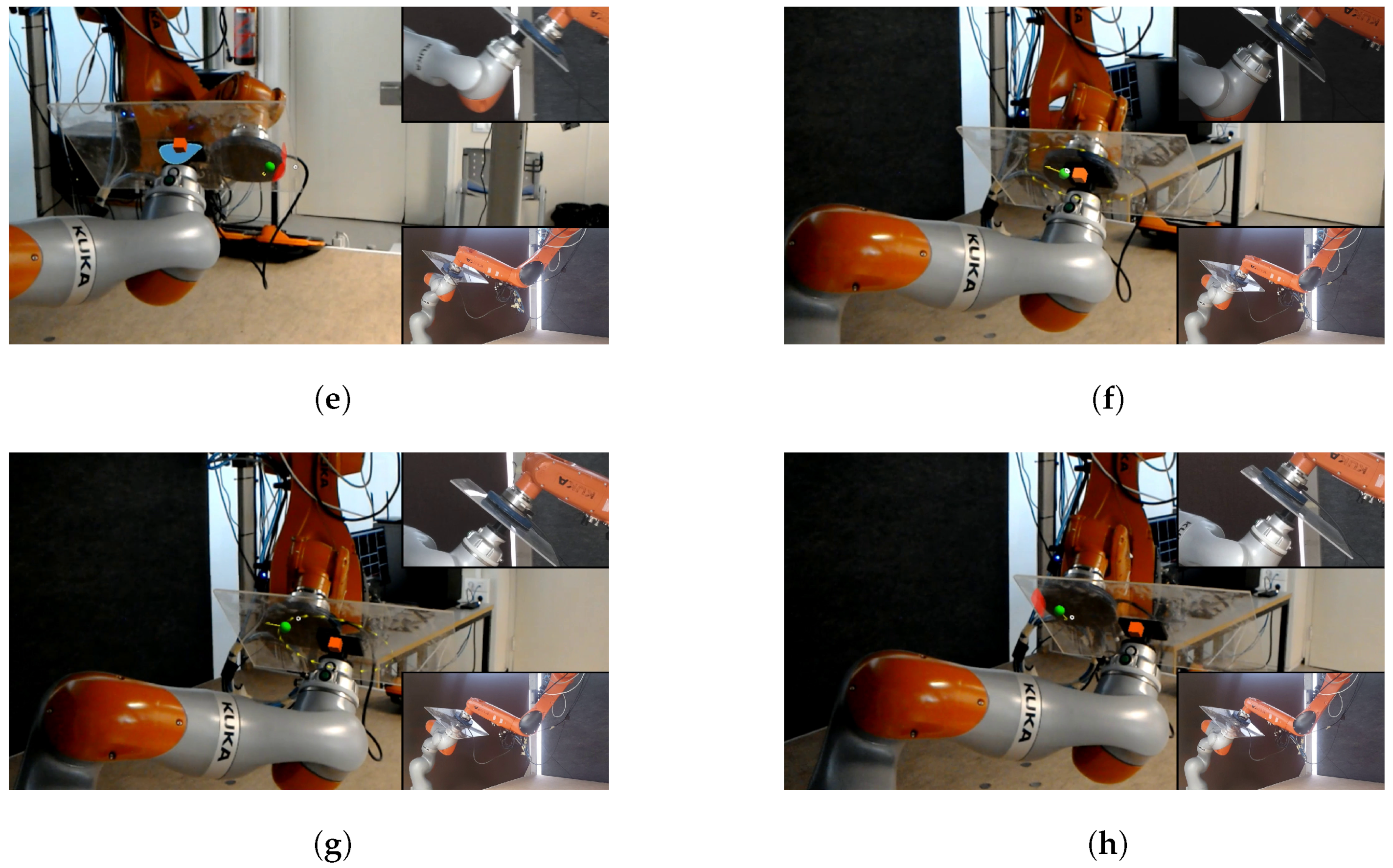
Figure 17 depicts several frames of the fourth experiment, which shows the performance of the overall system when the user commands simultaneously both robots using the proposed AR-based interface; see the video at https://media.upv.es/player/?id=29330720-8a8b-11ec-97cd-ab744f931636 (accessed on 26 April 2022) [84]. Figure 17a–d show how the user modifies the orientation of the WR while, at the same time, commanding the STR tool towards one side of the workpiece. Note that, in this situation, when the WR end-effector is close to one side of the 3D boundary, it is partially shown by the corresponding blue hologram. Furthermore, Figure 17e shows how the user simultaneously commands both robots to reach both 2D and 3D boundaries, which are partially shown by the red and blue holograms, respectively. It is worth noting that, in addition to the mentioned holograms, the user hears different warning sounds. Figure 17f,g show how the user modifies again the orientation of the WR while, at the same time, commanding the STR tool towards the other side of the workpiece. Finally, Figure 17h shows how the STR tool reaches the 2D boundary while the user is also commanding the WR end-effector.
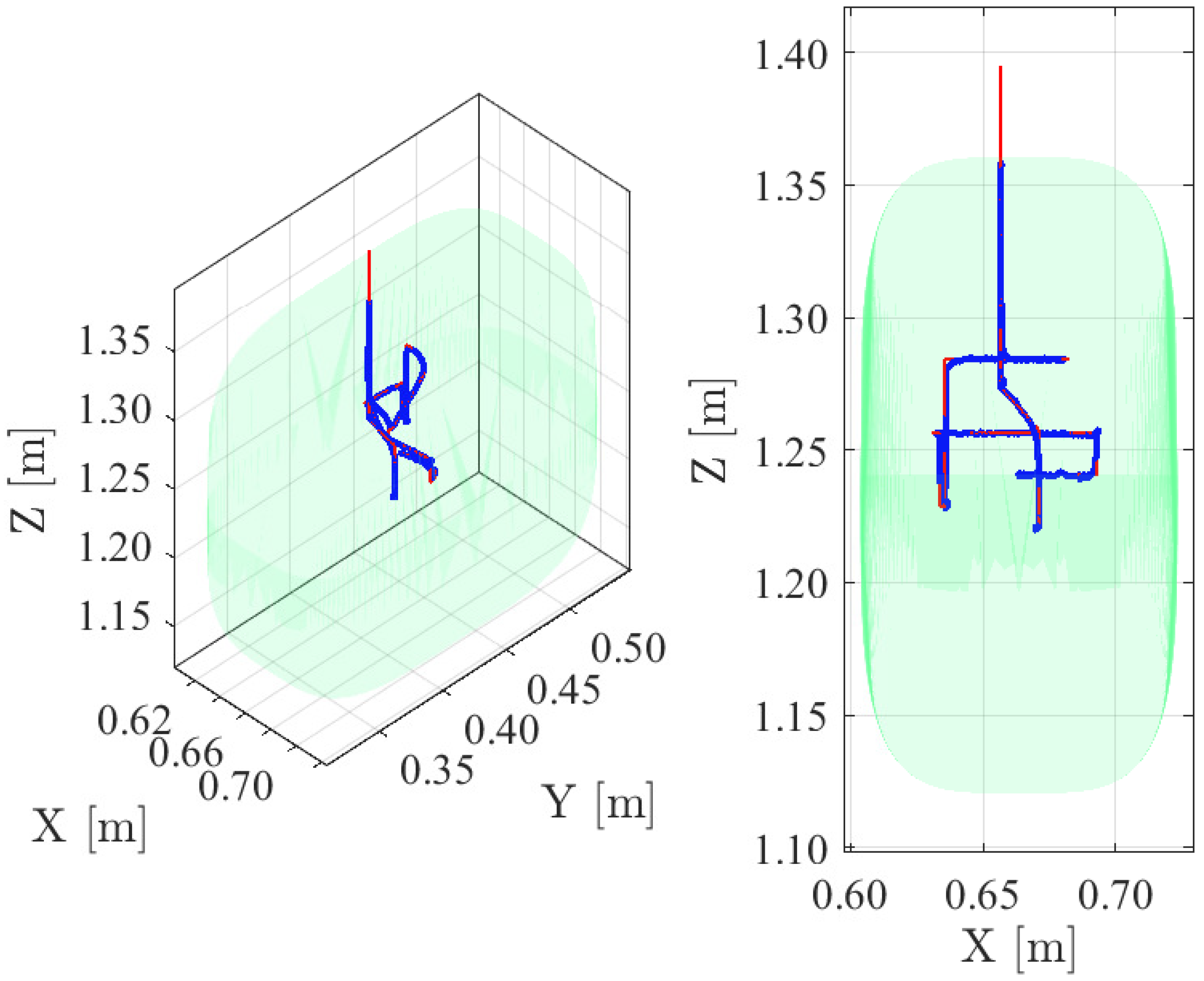
For the fourth experiment, Figure 18 shows the complete 2D trajectories followed by the user STR reference and the STR tool, whilst Figure 19 shows the complete 3D trajectories followed by the user WR reference and the WR end-effector. In both cases, as in the second and third experiments, the STR tool and the WR end-effector are automatically kept within the allowed regions despite the fact that, at some point, the user references exceed the 2D and 3D boundaries, respectively.
The teleoperation errors for the fourth experiment, in which the user commands simultaneously both robots using the proposed AR-based interface, are similar to those shown above for the second experiment (STR teleoperation) and third experiment (WR teleoperation): approximately cm standard deviation for the position of the STR tool—see Table 2—and approximately cm and standard deviation for the WR position and orientation, respectively—see Table 3. As mentioned above, these teleoperation error values include all the potential sources of error: communication delays, high-level and low-level control of both robots, teleoperation system, etc. Therefore, it is concluded that the accuracy achieved by the proposed AR-based approach for teleoperating the bimanual robot system is satisfactory.
5. Conclusions
A solution to improve the assisted bimanual robot teleoperation has been developed in this work using augmented reality (AR) technology and tools. In particular, a new AR interface using the Microsoft HoloLens glasses has been proposed to mitigate the problems in terms of user ergonomics and task performance (i.e., completion time and finishing quality) raised from the use of conventional PC-based user interfaces. In addition, this work has proposed and followed a new methodology to design and develop AR interfaces for bimanual robotic systems.
The effectiveness and applicability of the proposed AR interface were shown by means of real experimentation with an advanced bimanual robot application consisting of two robotic arms: a 7R cobot and a 6R industrial manipulator.
It is worth noting that several users, who tested both the conventional PC-based interface and the proposed AR interface, found the latter more intuitive and were able to conduct the robot teleoperation task faster. Note that when the users teleoperated the bimanual robot system using the conventional PC-based interface, most of them complained about the difficulty of checking whether the robots were performing the task correctly or not. In addition, the users indicated that with the conventional PC-based interface, it was not easy for them to command both robots simultaneously because they could not pay attention to so many reference signals shown. These facts negatively affected the performance of the users in terms of the time required to complete the task. Thus, the mentioned issues were mitigated with the proposed AR interface, significantly improving the user performance in the teleoperation task.
Another relevant remark is that the users also indicated that the warning sounds helped them in the early stages of the teleoperation task but, as the time of use of the interface increased, these sounds were annoying and they preferred only the visual warnings.
Author Contributions
Conceptualization, J.E.S. and L.G.; Funding acquisition, J.T.; Investigation, J.E.S., A.M. and L.G.; Methodology, J.E.S. and L.G.; Resources, J.T.; Software, A.G. and A.M.; Supervision, L.G. and J.T.; Writing—original draft, J.E.S.; Writing—review & editing, L.G. All authors have read and agreed to the published version of the manuscript.
Funding
This research was funded by the Spanish Government (Grant PID2020-117421RB-C21 funded by MCIN/AEI/10.13039/501100011033) and by the Generalitat Valenciana (Grants GV/2021/ 181 and ACIF/2019/007).
Conflicts of Interest
The authors declare no conflict of interest.
References
- Wang, W.; Chen, Y.; Li, R.; Zhang, Z.; Krovi, V.; Jia, Y. Human-robot collaboration for advanced manufacturing by learning from multi-modal human demonstrations. In Manufacturing In The Era Of 4th Industrial Revolution; World Scientific Publishing Co.: Singapore, 2021; pp. 87–116. [Google Scholar]
- Admoni, B.A.; Aronson, R.M.; Srinivasa, S.S.; Kitani, K.; Admoni, H. HARMONIC: A multimodal dataset of assistive human–robot collaboration. Int. J. Robot. Res. 2022, 41, 3–11. [Google Scholar] [CrossRef]
- Kim, S. Working With Robots: Human Resource Development Considerations in Human–Robot Interaction. Hum. Resour. Dev. Rev. 2022, 21, 48–74. [Google Scholar] [CrossRef]
- Gracia, L.; Solanes, J.E.; Muñoz-Benavent, P.; Valls Miro, J.; Perez-Vidal, C.; Tornero, J. Adaptive Sliding Mode Control for Robotic Surface Treatment Using Force Feedback. Mechatronics 2018, 52, 102–118. [Google Scholar] [CrossRef]
- Cardoso, J.C.S. Comparison of Gesture, Gamepad, and Gaze-Based Locomotion for VR Worlds. In Proceedings of the 22nd ACM Conference on Virtual Reality Software and Technology; Association for Computing Machinery: New York, NY, USA, 2016; pp. 319–320. [Google Scholar]
- Kitson, A.; Hashemian, A.M.; Stepanova, E.R.; Kruijff, E.; Riecke, B.E. Comparing leaning-based motion cueing interfaces for virtual reality locomotion. In Proceedings of the 2017 IEEE Symposium on 3D User Interfaces (3DUI), Los Angeles, CA, USA, 18–19 March 2017; pp. 73–82. [Google Scholar]
- Zhao, J.; Allison, R.S. Comparing head gesture, hand gesture and gamepad interfaces for answering Yes/No questions in virtual environments. Virtual Real. 2019, 24, 515–524. [Google Scholar] [CrossRef]
- Solanes, J.E.; Muñoz, A.; Gracia, L.; Martí, A.; Girbés-Juan, V.; Tornero, J. Teleoperation of industrial robot manipulators based on augmented reality. Int. J. Adv. Manuf. Technol. 2020, 111, 1077–1097. [Google Scholar] [CrossRef]
- Smith, C.; Karayiannidis, Y.; Nalpantidis, L.; Gratal, X.; Qi, P.; Dimarogonas, D.V.; Kragic, D. Dual arm manipulation—A survey. Robot. Auton. Syst. 2012, 60, 1340–1353. [Google Scholar] [CrossRef] [Green Version]
- Makris, S.; Tsarouchi, P.; Matthaiakis, A.S.; Athanasatos, A.; Chatzigeorgiou, X.; Stefos, M.; Giavridis, K.; Aivaliotis, S. Dual arm robot in cooperation with humans for flexible assembly. CIRP Ann. 2017, 66, 13–16. [Google Scholar] [CrossRef]
- Sepúlveda, D.; Fernández, R.; Navas, E.; Armada, M.; González-De-Santos, P. Robotic Aubergine Harvesting Using Dual-Arm Manipulation. IEEE Access 2020, 8, 121889–121904. [Google Scholar] [CrossRef]
- Chatzilygeroudis, K.; Fichera, B.; Lauzana, I.; Bu, F.; Yao, K.; Khadivar, F.; Billard, A. Benchmark for Bimanual Robotic Manipulation of Semi-Deformable Objects. IEEE Robot. Autom. Lett. 2020, 5, 2443–2450. [Google Scholar] [CrossRef]
- Garcia-Camacho, I.; Lippi, M.; Welle, M.C.; Yin, H.; Antonova, R.; Varava, A.; Borras, J.; Torras, C.; Marino, A.; Alenyá, G.; et al. Benchmarking Bimanual Cloth Manipulation. IEEE Robot. Autom. Lett. 2020, 5, 1111–1118. [Google Scholar] [CrossRef] [Green Version]
- Sintov, A.; Macenski, S.; Borum, A.; Bretl, T. Motion Planning for Dual-Arm Manipulation of Elastic Rods. IEEE Robot. Autom. Lett. 2020, 5, 6065–6072. [Google Scholar] [CrossRef]
- Mitash, C.; Shome, R.; Wen, B.; Boularias, A.; Bekris, K. Task-Driven Perception and Manipulation for Constrained Placement of Unknown Objects. IEEE Robot. Autom. Lett. 2020, 5, 5605–5612. [Google Scholar] [CrossRef]
- Clark, J.P.; Lentini, G.; Barontini, F.; Catalano, M.G.; Bianchi, M.; O’Malley, M.K. On the role of wearable haptics for force feedback in teleimpedance control for dual-arm robotic teleoperation. In Proceedings of the 2019 International Conference on Robotics and Automation (ICRA), Montreal, QC, Canada, 20–24 May 2019; pp. 5187–5193. [Google Scholar]
- Salehian, S.S.M.; Figueroa, N.; Billard, A. A unified framework for coordinated multi-arm motion planning. Int. J. Robot. Res. 2018, 37, 1205–1232. [Google Scholar] [CrossRef]
- Suarez, A.; Real, F.; Vega, V.M.; Heredia, G.; Rodriguez-Castaño, A.; Ollero, A. Compliant Bimanual Aerial Manipulation: Standard and Long Reach Configurations. IEEE Access 2020, 8, 88844–88865. [Google Scholar] [CrossRef]
- Wu, Q.; Li, M.; Qi, X.; Hu, Y.; Li, B.; Zhang, J. Coordinated control of a dual-arm robot for surgical instrument sorting tasks. Robot. Auton. Syst. 2019, 112, 1–12. [Google Scholar] [CrossRef]
- Rakita, D.; Mutlu, B.; Gleicher, M.; Hiatt, L.M. Shared control–based bimanual robot manipulation. Sci. Robot. 2019, 4, eaaw0955. [Google Scholar] [CrossRef] [PubMed]
- García, N.; Rosell, J.; Suárez, R. Motion Planning by Demonstration With Human-Likeness Evaluation for Dual-Arm Robots. IEEE Trans. Syst. Man Cybern. Syst. 2019, 49, 2298–2307. [Google Scholar] [CrossRef] [Green Version]
- Qu, J.; Zhang, F.; Wang, Y.; Fu, Y. Human-like coordination motion learning for a redundant dual-arm robot. Robot. Comput.-Integr. Manuf. 2019, 57, 379–390. [Google Scholar] [CrossRef]
- Joshi, R.P.; Tarapure, J.P.; Shibata, T. Electric Wheelchair-Humanoid Robot Collaboration for Clothing Assistance of the Elderly. In Proceedings of the 2020 13th International Conference on Human System Interaction (HSI), Tokyo, Japan, 6–8 June 2020; pp. 300–306. [Google Scholar]
- Li, Y.; Guo, S.; Mukai, T. Position Adjustment Control of A Nursing-care Robot Holding A Patient in Its Arms. In Proceedings of the 2019 IEEE International Conference on Mechatronics and Automation (ICMA), Tianjin, China, 4–7 August 2019; pp. 976–981. [Google Scholar]
- Chen, H.; Li, J.; Wan, W.; Huang, Z.; Harada, K. Integrating combined task and motion planning with compliant control. Int. J. Intell. Robot. Appl. 2020, 4, 149–163. [Google Scholar] [CrossRef]
- Zimmermann, S.; Hakimifard, G.; Zamora, M.; Poranne, R.; Coros, S. A Multi-Level Optimization Framework for Simultaneous Grasping and Motion Planning. IEEE Robot. Autom. Lett. 2020, 5, 2966–2972. [Google Scholar] [CrossRef]
- Parigi Polverini, M.; Zanchettin, A.M.; Rocco, P. A constraint-based programming approach for robotic assembly skills implementation. Robot. Comput.-Integr. Manuf. 2019, 59, 69–81. [Google Scholar] [CrossRef]
- Zhong, F.; Wang, Y.; Wang, Z.; Liu, Y. Dual-Arm Robotic Needle Insertion With Active Tissue Deformation for Autonomous Suturing. IEEE Robot. Autom. Lett. 2019, 4, 2669–2676. [Google Scholar] [CrossRef]
- Bandala, M.; West, C.; Monk, S.; Montazeri, A.; Taylor, C.J. Vision-Based Assisted Tele-Operation of a Dual-Arm Hydraulically Actuated Robot for Pipe Cutting and Grasping in Nuclear Environments. Robotics 2019, 8, 42. [Google Scholar] [CrossRef] [Green Version]
- Girbés-Juan, V.; Schettino, V.; Demiris, Y.; Tornero, J. Haptic and Visual Feedback Assistance for Dual-Arm Robot Teleoperation in Surface Conditioning Tasks. IEEE Trans. Haptics 2021, 14, 44–56. [Google Scholar] [CrossRef]
- García, A.; Solanes, J.E.; Gracia, L.; Muñoz-Benavent, P.; Girbés-Juan, V.; Tornero, J. Bimanual robot control for surface treatment tasks. Int. J. Syst. Sci. 2022, 53, 74–107. [Google Scholar] [CrossRef]
- McConachie, D.; Dobson, A.; Ruan, M.; Berenson, D. Manipulating deformable objects by interleaving prediction, planning, and control. Int. J. Robot. Res. 2020, 39, 957–982. [Google Scholar] [CrossRef]
- Liang, J.; Xu, Z.; Zhou, X.; Li, S.; Ye, G. Recurrent Neural Networks-Based Collision-Free Motion Planning for Dual Manipulators Under Multiple Constraints. IEEE Access 2020, 8, 54225–54236. [Google Scholar] [CrossRef]
- Ibarguren, A.; Eimontaite, I.; Outón, J.L.; Fletcher, S. Dual Arm Co-Manipulation Architecture with Enhanced Human–Robot Communication for Large Part Manipulation. Sensors 2020, 20, 6151. [Google Scholar] [CrossRef]
- Brantner, G.; Khatib, O. Controlling Ocean One: Human–robot collaboration for deep-sea manipulation. J. Field Robot. 2021, 38, 28–51. [Google Scholar] [CrossRef]
- Niemeyer, G.; Preusche, C.; Stramigioli, S.; Lee, D. Telerobotics. In Springer Handbook of Robotics; Siciliano, B., Khatib, O., Eds.; Springer International Publishing: Cham, Switzerland, 2016; pp. 1085–1108. [Google Scholar]
- Chen, H.; Huang, P.; Liu, Z. Mode Switching-Based Symmetric Predictive Control Mechanism for Networked Teleoperation Space Robot System. IEEE/ASME Trans. Mechatron. 2019, 24, 2706–2717. [Google Scholar] [CrossRef]
- Abi-Farraj, F.; Pacchierotti, C.; Arenz, O.; Neumann, G.; Giordano, P.R. A Haptic Shared-Control Architecture for Guided Multi-Target Robotic Grasping. IEEE Trans. Haptics 2020, 13, 270–285. [Google Scholar] [CrossRef] [PubMed] [Green Version]
- Isop, W.A.; Gebhardt, C.; Nägeli, T.; Fraundorfer, F.; Hilliges, O.; Schmalstieg, D. High-Level Teleoperation System for Aerial Exploration of Indoor Environments. Front. Robot. AI 2019, 6, 95. [Google Scholar] [CrossRef] [PubMed] [Green Version]
- Sivčev, S.; Coleman, J.; Omerdić, E.; Dooly, G.; Toal, D. Underwater manipulators: A review. Ocean Eng. 2018, 163, 431–450. [Google Scholar] [CrossRef]
- Kono, H.; Mori, T.; Ji, Y.; Fujii, H.; Suzuki, T. Development of Perilous Environment Estimation System Using a Teleoperated Rescue Robot with On-board LiDAR. In Proceedings of the 2019 IEEE/SICE International Symposium on System Integration (SII), Paris, France, 14–16 January 2019; pp. 7–10. [Google Scholar]
- Yoon, H.; Jeong, J.H.; Yi, B. Image-Guided Dual Master–Slave Robotic System for Maxillary Sinus Surgery. IEEE Trans. Robot. 2018, 34, 1098–1111. [Google Scholar] [CrossRef]
- Saracino, A.; Oude-Vrielink, T.J.C.; Menciassi, A.; Sinibaldi, E.; Mylonas, G.P. Haptic Intracorporeal Palpation Using a Cable-Driven Parallel Robot: A User Study. IEEE Trans. Biomed. Eng. 2020, 67, 3452–3463. [Google Scholar] [CrossRef]
- Chen, Y.; Zhang, S.; Wu, Z.; Yang, B.; Luo, Q.; Xu, K. Review of surgical robotic systems for keyhole and endoscopic procedures: State of the art and perspectives. Front. Med. 2020, 14, 382–403. [Google Scholar] [CrossRef]
- Kapoor, A.; Li, M.; Taylor, R.H. Spatial Motion Constraints for Robot Assisted Suturing Using Virtual Fixtures. In Medical Image Computing and Computer-Assisted Intervention–MICCAI 2005; Duncan, J.S., Gerig, G., Eds.; Springer: Berlin/Heidelberg, Germany, 2005; pp. 89–96. [Google Scholar]
- Johnson, M.; Vera, A. No AI Is an Island: The Case for Teaming Intelligence. AI Mag. 2019, 40, 16–28. [Google Scholar] [CrossRef] [Green Version]
- Selvaggio, M.; Abi-Farraj, F.; Pacchierotti, C.; Giordano, P.R.; Siciliano, B. Haptic-Based Shared-Control Methods for a Dual-Arm System. IEEE Robot. Autom. Lett. 2018, 3, 4249–4256. [Google Scholar] [CrossRef] [Green Version]
- Nicolis, D.; Palumbo, M.; Zanchettin, A.M.; Rocco, P. Occlusion-Free Visual Servoing for the Shared Autonomy Teleoperation of Dual-Arm Robots. IEEE Robot. Autom. Lett. 2018, 3, 796–803. [Google Scholar] [CrossRef]
- Lu, Z.; Huang, P.; Liu, Z. Predictive Approach for Sensorless Bimanual Teleoperation Under Random Time Delays With Adaptive Fuzzy Control. IEEE Trans. Ind. Electron. 2018, 65, 2439–2448. [Google Scholar] [CrossRef]
- Girbés-Juan, V.; Schettino, V.; Gracia, L.; Solanes, J.E.; Demeris, Y.; Tornero, J. Combining haptics and inertial motion capture to enhance remote control of a dual-arm robot. J. Multimodal User Interfaces 2022, 1–20, in press. [Google Scholar] [CrossRef]
- Gorjup, G.; Dwivedi, A.; Elangovan, N.; Liarokapis, M. An Intuitive, Affordances Oriented Telemanipulation Framework for a Dual Robot Arm Hand System: On the Execution of Bimanual Tasks. In Proceedings of the 2019 IEEE/RSJ International Conference on Intelligent Robots and Systems (IROS), Macau, China, 3–8 November 2019; pp. 3611–3616. [Google Scholar]
- Selvaggio, M.; Ghalamzan, A.; Moccia, R.; Ficuciello, F.; Siciliano, B. Haptic-guided shared control for needle grasping optimization in minimally invasive robotic surgery. In Proceedings of the IEEE/RSJ International Conference on Intelligent Robots and Systems, Macau, China, 3–8 November 2019. [Google Scholar]
- Lipton, J.I.; Fay, A.J.; Rus, D. Baxter’s Homunculus: Virtual Reality Spaces for Teleoperation in Manufacturing. IEEE Robot. Autom. Lett. 2018, 3, 179–186. [Google Scholar] [CrossRef] [Green Version]
- Bian, F.; Li, R.; Zhao, L.; Liu, Y.; Liang, P. Interface Design of a Human-Robot Interaction System for Dual-Manipulators Teleoperation Based on Virtual Reality. In Proceedings of the 2018 IEEE International Conference on Information and Automation (ICIA), Wuyishan, China, 11–13 August 2018; pp. 1361–1366. [Google Scholar] [CrossRef]
- Tonin, L.; Millan, J.D.R. Noninvasive Brain-Machine Interfaces for Robotic Devices. In Annual Review of Control, Robotics, and Autonomous Systems; Leonard, N., Ed.; Annual Reviews: Palo Alto, CA, USA, 2021; Volume 4, pp. 191–214. [Google Scholar] [CrossRef]
- Tang, G.; Shi, Q.; Zhang, Z.; He, T.; Sun, Z.; Lee, C. Hybridized wearable patch as a multi-parameter and multi-functional human-machine interface. Nano Energy 2021, 81, 105582. [Google Scholar] [CrossRef]
- Jin, Y.; Chen, J.; Zhang, S.; Chen, W.; Zheng, X. Invasive Brain Machine Interface System. In Neural Interface: Frontiers and Applications; Zheng, X., Ed.; Springer: Singapore, 2019; pp. 67–89. [Google Scholar] [CrossRef]
- Dumitrescu, C.; Costea, I.M.; Semenescu, A. Using Brain-Computer Interface to Control a Virtual Drone Using Non-Invasive Motor Imagery and Machine Learning. Appl. Sci. 2021, 11, 1876. [Google Scholar] [CrossRef]
- Xu, B.; Li, W.; Liu, D.; Zhang, K.; Miao, M.; Xu, G.; Song, A. Continuous Hybrid BCI Control for Robotic Arm Using Noninvasive Electroencephalogram, Computer Vision, and Eye Tracking. Mathematics 2022, 10, 618. [Google Scholar] [CrossRef]
- Cao, L.; Li, G.; Xu, Y.; Zhang, H.; Shu, X.; Zhang, D. A brain-actuated robotic arm system using non-invasive hybrid brain-computer interface and shared control strategy. J. Neural Eng. 2021, 18, 046045. [Google Scholar] [CrossRef]
- Muñoz, A.; Mahiques, X.; Solanes, J.E.; Martí, A.; Gracia, L.; Tornero, J. Mixed reality-based user interface for quality control inspection of car body surfaces. J. Manuf. Syst. 2019, 53, 75–92. [Google Scholar] [CrossRef]
- Muñoz, A.; Martí, A.; Mahiques, X.; Gracia, L.; Solanes, J.E.; Tornero, J. Camera 3D positioning mixed reality-based interface to improve worker safety, ergonomics and productivity. CIRP J. Manuf. Sci. Technol. 2020, 28, 24–37. [Google Scholar] [CrossRef]
- Chu, Y.B.; Chang, C.W. A Mobile Augmented Reality Interface on Additive Manufacturing. In Advances in Electrical and Electronic Engineering and Computer Science; Zakaria, Z., Emamian, S.S., Eds.; Springer: Singapore, 2021; pp. 1–12. [Google Scholar]
- Tedesco, A.; Dallet, D.; Arpaia, P. Augmented Reality (AR) and Brain-Computer Interface (BCI): Two Enabling Technologies for Empowering the Fruition of Sensor Data in the 4.0 Era. In Sensors and Microsystems; Di Francia, G., Di Natale, C., Eds.; Springer International Publishing: Cham, Switzerland, 2021; pp. 85–91. [Google Scholar]
- Craig, A.B. Chapter 2-Augmented Reality Concepts. In Understanding Augmented Reality; Craig, A.B., Ed.; Morgan Kaufmann: Boston, MA, USA, 2013; pp. 39–67. [Google Scholar]
- Li, C.; Fahmy, A.; Sienz, J. An Augmented Reality Based Human-Robot Interaction Interface Using Kalman Filter Sensor Fusion. Sensors 2019, 19, 4586. [Google Scholar] [CrossRef] [Green Version]
- Rosen, E.; Whitney, D.; Phillips, E.; Chien, G.; Tompkin, J.; Konidaris, G.; Tellex, S. Communicating and controlling robot arm motion intent through mixed-reality head-mounted displays. Int. J. Robot. Res. 2019, 38, 1513–1526. [Google Scholar] [CrossRef]
- Gadre, S.Y.; Rosen, E.; Chien, G.; Phillips, E.; Tellex, S.; Konidaris, G. End-User Robot Programming Using Mixed Reality. In Proceedings of the 2019 International Conference on Robotics and Automation (ICRA), Montreal, QC, Canada, 20–24 May 2019; pp. 2707–2713. [Google Scholar]
- Mistry, P.; Maes, P. SixthSense: A Wearable Gestural Interface. In ACM Siggraph Asia 2009 Sketches; SIGGRAPH ASIA ’09; Association for Computing Machinery: New York, NY, USA, 2009. [Google Scholar] [CrossRef]
- Ismail, A.W.; Billinghurst, M.; Sunar, M.S.; Yusof, C.S. Designing an Augmented Reality Multimodal Interface for 6DOF Manipulation Techniques. In Intelligent Systems and Applications; Arai, K., Kapoor, S., Bhatia, R., Eds.; Springer International Publishing: Cham, Switzerland, 2019; pp. 309–322. [Google Scholar]
- Nakamura, Y.; Hanafusa, H.; Yoshikawa, T. Task-Priority Based Redundancy Control of Robot Manipulators. Int. J. Robot. Res. 1987, 6, 3–15. [Google Scholar] [CrossRef]
- Nenchev, D. Tracking manipulator trajectories with ordinary singularities: A null space-based approach. Int. J. Robot. Res. 1995, 14, 399–404. [Google Scholar] [CrossRef]
- Garelli, F.; Gracia, L.; Sala, A.; Albertos, P. Sliding mode speed auto-regulation technique for robotic tracking. Robot. Auton. Syst. 2011, 59, 519–529. [Google Scholar] [CrossRef] [Green Version]
- Garelli, F.; Mantz, R.; De Battista, H. Sliding mode reference conditioning to preserve decoupling of stable systems. Chem. Eng. Sci. 2007, 62, 4705–4716. [Google Scholar] [CrossRef]
- Video of the PC-Based Interface. 2022. Available online: https://media.upv.es/player/?id=15ffabe0-a733-11eb-a0b0-2fbcb59aaef7 (accessed on 26 April 2022).
- Microsoft Hololens. HoloLens (1st Gen) Hardware Details. Available online: https://docs.microsoft.com/en-us/windows/mixed-reality/hololens-hardware-details (accessed on 26 April 2022).
- Microsoft Hololens (2nd Gen) Hardware Details. Available online: https://www.microsoft.com/en-us/hololens/hardware (accessed on 26 April 2022).
- Hess, R. Blender Foundations: The Essential Guide to Learning Blender 2.6; Focal Press, Elsevier: Oxford, UK, 2010; Available online: https://www.sciencedirect.com/book/9780240814308/blender-foundations (accessed on 26 April 2022).
- Jackson, S. Unity 3D UI Essentials; Packt Publishing: Birmingham, UK, 2015; Available online: https://dl.acm.org/citation.cfm?id=2789365 (accessed on 26 April 2022).
- Unity. Shaders Core Concepts. Available online: https://docs.unity3d.com/Manual/Shaders.html (accessed on 26 April 2022).
- First Experiment Video. 2022. Available online: https://media.upv.es/player/?id=a64014f0-8a5a-11ec-ac0a-b3aa330d3dad (accessed on 26 April 2022).
- Second Experiment Video. 2022. Available online: https://media.upv.es/player/?id=9504e6f0-8a61-11ec-b7c7-7d27dda7c5d5 (accessed on 26 April 2022).
- Third Experiment Video. 2022. Available online: https://media.upv.es/player/?id=17d88200-8f0b-11ec-be22-d786eca82090 (accessed on 26 April 2022).
- Fourth Experiment Video. 2022. Available online: https://media.upv.es/player/?id=29330720-8a8b-11ec-97cd-ab744f931636 (accessed on 26 April 2022).
Figure 1.
Bimanual application setup and block diagram (for further details, refer to [31]). (a) Previous setup used for the real experimentation. (b) Block control diagram for both robots (WR and STR).
Figure 1.
Bimanual application setup and block diagram (for further details, refer to [31]). (a) Previous setup used for the real experimentation. (b) Block control diagram for both robots (WR and STR).

Figure 2.
Conventional PC-based user interface: visual references and effects. (a) Video: 0 m 20 s. (b) Video: 0 m 23 s.
Figure 2.
Conventional PC-based user interface: visual references and effects. (a) Video: 0 m 20 s. (b) Video: 0 m 23 s.

Figure 3.
Frames of the video showing the functionalities of the conventional user interface. See the video at https://media.upv.es/player/?id=15ffabe0-a733-11eb-a0b0-2fbcb59aaef7 (accessed on 26 April 2022) [75].(a) Video: 0 m 20 s. (b) Video: 1 m 00 s. (c) Video: 1 m 24 s. (d) Video: 1 m 33 s. (e) Video: 1 m 43 s.

Figure 4.
New setup used for the real experimentation.

Figure 5.
Flowchart of the methodology proposed in this work for designing the AR-based interface.

Figure 6.
Proposed holograms for the robot references. (a) WR: translation reference hologram. (b) WR: rotation reference hologram. (c) STR: translation reference hologram.
Figure 6.
Proposed holograms for the robot references. (a) WR: translation reference hologram. (b) WR: rotation reference hologram. (c) STR: translation reference hologram.

Figure 7.
Proposed holograms for the robot 3D and 2D boundaries. (a) 3D boundary hologram (full). (b) 3D boundary hologram (local). (c) 2D boundary hologram (full). (d) 2D boundary hologram (local).
Figure 7.
Proposed holograms for the robot 3D and 2D boundaries. (a) 3D boundary hologram (full). (b) 3D boundary hologram (local). (c) 2D boundary hologram (full). (d) 2D boundary hologram (local).

Figure 8.
Material shader designed for controlling the visibility of the 3D and 2D boundaries depending on the proximity of the WR end-effector and STR tool, respectively.
Figure 8.
Material shader designed for controlling the visibility of the 3D and 2D boundaries depending on the proximity of the WR end-effector and STR tool, respectively.

Figure 9.
First experiment: frames of the video showing the functionalities of the proposed AR-based interface. See the video at https://media.upv.es/player/?id=a64014f0-8a5a-11ec-ac0a-b3aa330d3dad (accessed on 26 April 2022) [81]. (a) Video: 0 m 20 s. (b) Video: 0 m 23 s. (c) Video: 0 m 30 s. (d) Video: 0 m 36 s. (e) Video: 0 m 43 s. (f) Video: 0 m 57 s.

Figure 10.
Second experiment: frames of the video showing the performance of the 2D boundary and the STR reference hologram. See the video at https://media.upv.es/player/?id=9504e6f0-8a61-11ec-b7c7-7d27dda7c5d5 (accessed on 26 April 2022) [82]. (a) Video: 0 m 31 s. (b) Video: 0 m 41 s. (c) Video: 1 m 05 s. (d) Video: 1 m 46 s.

Figure 11.
The 2D trajectory performance for the second experiment, showing the 2D boundary and the STR reference hologram (see the video at https://media.upv.es/player/?id=9504e6f0-8a61-11ec-b7c7-7d27dda7c5d5 (accessed on 26 April 2022) [82]): 2D allowed workpiece region in green; trajectory followed by the user reference in thin red line; and trajectory followed by the STR tool in thick blue line.

Figure 12.
Performance of the STR position teleoperation for the second experiment. First two graphs: user position references in thin red line, actual position values of the STR tool on the workpiece surface (coordinates relative to the surface) in thick blue line, and position limits given by the 2D boundary constraint in dashed lines. Bottom graph: activation of the 2D boundary constraint for the position of the STR tool on the workpiece surface.

Figure 13.
Third experiment: frames of the video showing the performance of the 3D boundary and the WR reference hologram. See the video at https://media.upv.es/player/?id=17d88200-8f0b-11ec-be22-d786eca82090 (accessed on 26 April 2022) [83]. (a) Video: 0 m 22 s. (b) Video: 0 m 24 s. (c) Video: 1 m 04 s. (d) Video: 1 m 46 s.

Figure 14.
The 3D trajectory performance for the third experiment, showing the 3D boundary and the WR reference hologram (see the video at https://media.upv.es/player/?id=17d88200-8f0b-11ec-be22-d786eca82090 (accessed on 26 April 2022) [83]): 3D allowed region in green; trajectory followed by the user reference in thin red line; and trajectory followed by the WR end-effector in thick blue line.

Figure 15.
Performance of the WR position teleoperation for the third experiment. First three graphs: user position references in thin red line, actual position values of the workpiece in thick blue line, and position limits given by the 3D boundary constraint in dashed lines. Bottom graph: activation of the 3D boundary constraint for the workpiece position.

Figure 16.
Performance of the WR angle teleoperation for the third experiment: user angular references in thin red line and actual angular values of the workpiece in thick blue line.
Figure 16.
Performance of the WR angle teleoperation for the third experiment: user angular references in thin red line and actual angular values of the workpiece in thick blue line.

Figure 17.
Fourth experiment: frames of the video showing the simultaneous teleoperation of both robots with the proposed AR-based interface. See the video at https://media.upv.es/player/?id=29330720-8a8b-11ec-97cd-ab744f931636 (accessed on 26 April 2022) [84]. (a) Video: 1 m 19 s. (b) Video: 1 m 44 s. (c) Video: 1 m 54 s. (d) Video: 1 m 55 s. (e) Video: 2 m 13 s. (f) Video: 2 m 42 s. (g) Video: 2 m 52 s. (h) Video: 3 m 05 s.


Figure 18.
The 2D trajectory performance for the fourth experiment, showing the simultaneous teleoperation of both robots (see the video at https://media.upv.es/player/?id=29330720-8a8b-11ec-97cd-ab744f931636 (accessed on 26 April 2022) [84]): 2D allowed workpiece region in green; trajectory followed by the user reference in thin red line; and trajectory followed by the STR tool in thick blue line.

Figure 19.
The 3D trajectory performance for the fourth experiment, showing the simultaneous teleoperation of both robots (see the video at https://media.upv.es/player/?id=29330720-8a8b-11ec-97cd-ab744f931636 (accessed on 26 April 2022) [84]): 3D allowed region in green; trajectory followed by the user reference in thin red line; and trajectory followed by the WR end-effector in thick blue line.


Table 1.
Application requirements.
| The user should have the option to see the full boundaries when required |
| The part of the boundary activated should be indicated (e.g., visually, sound, etc.) |
| STR tool reference direction should be indicated |
| WR rotation reference direction should be indicated |
| The new interface should use a similar interaction device to that of the previous PC-based interface (i.e., gamepad, joystick, or similar) |
| Alarm sounds should be used to indicate boundary activation |
| The user should have the option to remove all holograms |
| Holograms should not disturb the user visibility during the task |
| The user should have the option to configure, activate, and deactivate the alarm sounds |
Table 2.
Teleoperation errors for the 2D position of the STR tool on the workpiece surface.
| Position (cm) | ||
|---|---|---|
| Maximum deviation | 1.8 | 3.2 |
| Standard deviation | 0.5 | 0.8 |
Table 3.
Teleoperation errors for the pose (i.e., position and orientation) of the WR.
| Position (cm) | Orientation (deg) | |||||
|---|---|---|---|---|---|---|
| Maximum deviation | 1.2 | 0.9 | 0.1 | 1.7 | 1.5 | 1.7 |
| Standard deviation | 0.4 | 0.3 | 0.03 | 0.3 | 0.2 | 0.2 |
Publisher’s Note: MDPI stays neutral with regard to jurisdictional claims in published maps and institutional affiliations. |
© 2022 by the authors. Licensee MDPI, Basel, Switzerland. This article is an open access article distributed under the terms and conditions of the Creative Commons Attribution (CC BY) license (https://creativecommons.org/licenses/by/4.0/).
Share and Cite
MDPI and ACS Style
García, A.; Solanes, J.E.; Muñoz, A.; Gracia, L.; Tornero, J. Augmented Reality-Based Interface for Bimanual Robot Teleoperation. Appl. Sci. 2022, 12, 4379. https://doi.org/10.3390/app12094379
AMA Style
García A, Solanes JE, Muñoz A, Gracia L, Tornero J. Augmented Reality-Based Interface for Bimanual Robot Teleoperation. Applied Sciences. 2022; 12(9):4379. https://doi.org/10.3390/app12094379
Chicago/Turabian StyleGarcía, Alberto, J. Ernesto Solanes, Adolfo Muñoz, Luis Gracia, and Josep Tornero. 2022. "Augmented Reality-Based Interface for Bimanual Robot Teleoperation" Applied Sciences 12, no. 9: 4379. https://doi.org/10.3390/app12094379
Note that from the first issue of 2016, this journal uses article numbers instead of page numbers. See further details here.