
Remote-Controlled Method with Force and Visual Assists Based on Time to Collision for Mobile Robot


Graduate School of Maritime Sciences, Kobe University, Kobe 658-0022, Japan
*
Authors to whom correspondence should be addressed.
Appl. Sci. 2022, 12(8), 3727; https://doi.org/10.3390/app12083727
Submission received: 17 February 2022
/
Revised: 25 March 2022
/
Accepted: 3 April 2022
/
Published: 7 April 2022
(This article belongs to the Special Issue Recent Development and Applications of Remote Robot Systems)
Abstract
:Various remote-controlled methods have been developed to improve operability using force or visual assists; however, using only force or visual assists may deteriorate the operability or safety performance. Therefore, a remote-controlled method with both force and visual assists is proposed to improve the operability while maintaining safety performance. The proposed remote-controlled system consists of a wheeled mobile robot, control device, and monitor. The force assist is generated using the time to collision (TTC), which is the predicted time of collision of the mobile robot against an obstacle. This force assist is applied to the operator using a control device to achieve collision avoidance. Using a visual assist, a predicted trajectory for the mobile robot based on the TTC is generated. For operability improvement, this predicted trajectory with color gradation is shown on the monitor. In summary, the achievement of operability improvement while maintaining safety performance is confirmed from experimental results using the proposed method.
1. Introduction
The technology of autonomous and remote-controlled mobile robots has become more popular for various situations and objectives. Autonomous robots used in service situations have been studied to assist in human tasks [1,2,3,4]. In the industry context, path planning methods with collision avoidance have been studied [5,6,7,8]. Therefore, autonomous robots have been mainly used in constructed environments, such as for motion tracking, cleaning inside a building, and manufacturing robots in an assembly line [9,10,11]. However, there are several situations in which autonomous robots do not work properly in an unconstructed environment that requires flexibility.
For an unconstructed environment such as an investigation in military and civilian fields, remote-controlled robots have been mainly used because humans can operate remote-controlled robots flexibly [12,13]. In the field of healthcare, remote-controlled robots have been investigated to support hospital staff [14,15]. In an industry scenario, remote-controlled robots that investigate and track complex environments have been developed [16,17,18,19]. In life care, remote-controlled robots have been utilized to assist humans [20]. Furthermore, in situations of disaster response and hazardous areas, remote-controlled robots have been widely used for inspection [21,22,23].
These remote-controlled robots allow us to complete a variety of activities based on the operator’s judgment. A monitor and a control device are used for the remote-controlled system. The operator operates the remote-controlled robot by using the control device while checking the monitor, which displays the visual information from the visual sensors. To operate flexibly, expert operators who understand and are capable of training the remote-controlled robot well are required. Thus, operating a remote-controlled robot is difficult and includes the possibility of operational mistakes. This is because it is difficult for the operator to understand real environmental situations by using a monitor that only shows visual information. Therefore, for expert operation, numerous stages of training are required for the operator to recognize the surroundings from the visual information.
Methods for improving the operability of the remote-controlled robot with respect to the mechanical design of the control device and the control method of the operation assist have been reported [24,25]. This study focuses on the control method, because the control method can be adapted more easily to see improvements, as compared to varying the mechanical design of the control device for obtaining the same improved performance. To enhance the control method of the operation assist and thereby increase the operability of the remote-controlled robot, force and visual assists have been studied in particular. The force assist for the mobile robot has been widely researched to improve the operability and the safety performance. While operating a remote-controlled robot, force feedback is frequently employed to assist human operators in improving their perception of environments to assist their operation skills [26,27,28,29,30]. Meanwhile, visual assists for remote-controlled robots have been widely studied and used for real situations to improve the operability. For example, remote-controlled methods using visual assists have been studied using several types of sensors [31,32,33]. However, it is difficult to achieve safety performance by using only a visual assist [34,35]. Hence, the evaluation of a combination method with force and visual assists is a meaningful study for remote-controlled methods. Therefore, force and visual assists of remote-controlled robots are proposed in this study to improve operability.
This study proposes a remote-controlled method with force and visual assists to improve the operability and safety performance for a fully remote-controlled wheeled mobile robot. The force assist was generated to ensure the safety performance of the remote-controlled robot. In contrast, visual assist was used to improve the operability of the remote-controlled robot. The force assist based on the time to collision (TTC) was applied to avoid collisions and achieve safe performance. The presence of a force assist is an important factor that influences the operability. The increased dependency on the force assist provides a more frequent force feedback to the control device compared to a system with decreased use of the force assist. To improve operability, a proposed technique that generates a lower dependence on the force assist was required. Furthermore, a visual assist, which shows the predicted trajectory of the mobile robot on the operator’s monitor, was applied to improve the operability. The predicted trajectory was based on the TTC and mobile robot velocity. The proposed strategy can improve the operability while ensuring safety performance. The proposed method was evaluated by comparing the experimental results from start to finish, the number of back operations, and the number of collisions. The experimental results obtained using the proposed method show that the operability and safety performance are improved. In this study, an unconstructed environment such as a disaster and hazardous environment where there are many obstacles inside of buildings was considered for improving the operability and safety performance.
The remainder of this paper is organized as follows. The remote-controlled system is described in Section 2. Section 3 proposes a remote-controlled method with force and visual assists for mobile robots. Section 4 presents the experimental results to confirm the validity of the proposed method. Finally, Section 5 concludes the study.
2. Modeling
2.1. System Configuration
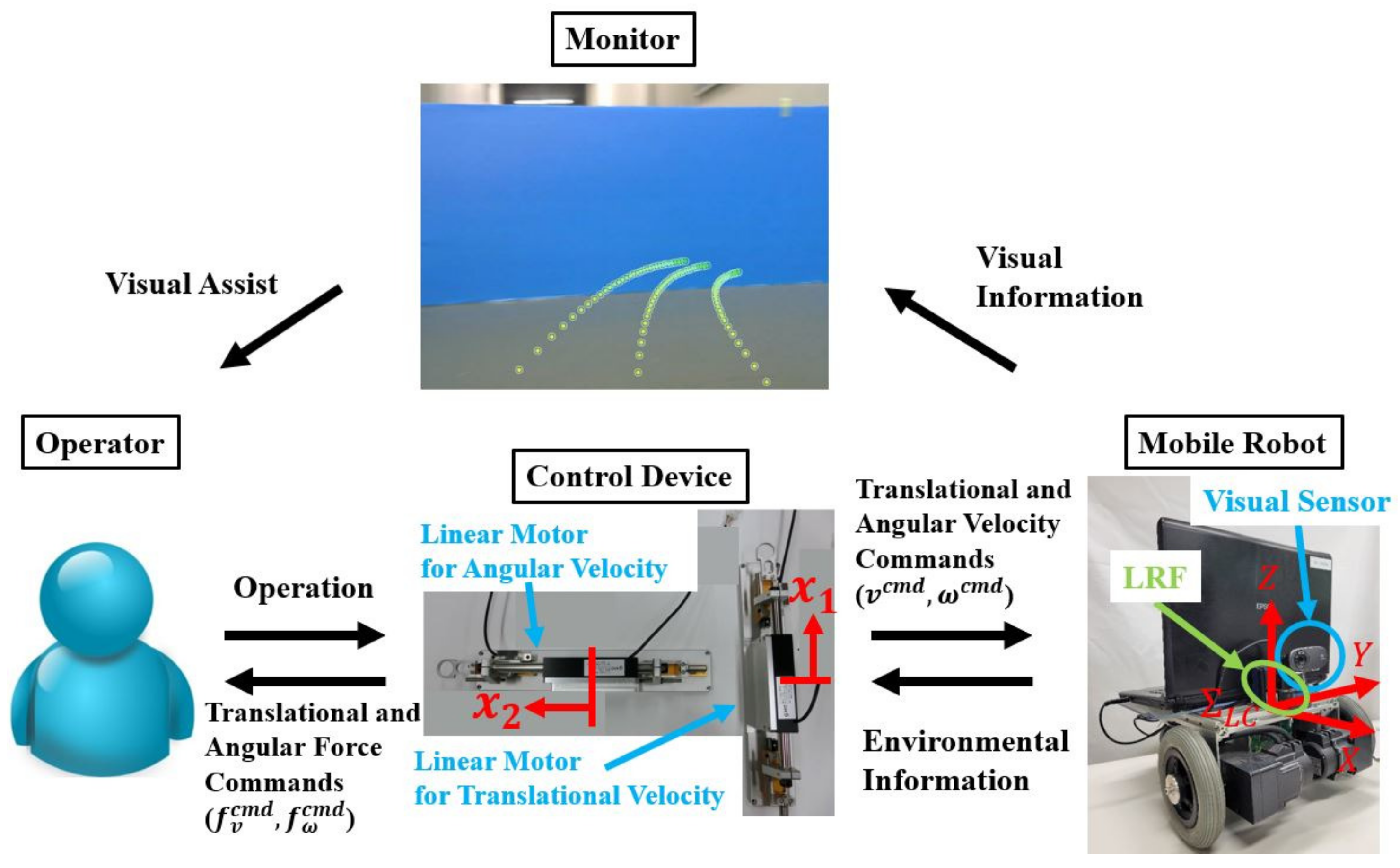
Figure 1 shows the system configuration of remote-controlled robot with visual and force feedback. This system consists of a monitor, a control device, and a mobile robot. The laser range finder (LRF) and visual sensor have been installed on the mobile robot. The LRF can detect a wide range of high-precision environments around the mobile robot. Two PCs were used to control the mobile robot, monitor, and control device. The user datagram protocol (UDP), which is a communication protocol across the Internet, was used to connect the two PCs. The environmental information was measured by the LRF and the visual sensor and sent from the PC of the mobile robot to the PC at the operator’s side. The translational and angular velocity commands (, ) were sent from the PC at the operator’s side to the mobile robot’s PC.
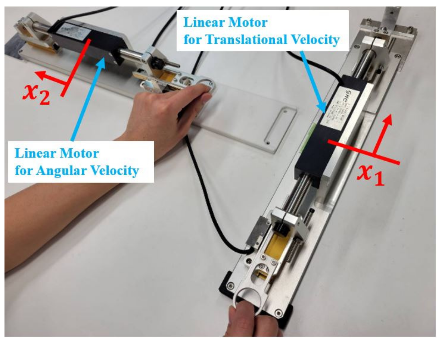
The mobile robot used is an i-Cart mini robot [36]. The mobile robot moves according to the velocity commands from the operator. To measure the environmental information, the LRF produced by HOKUYO AUTOMATIC CO., LTD. was used [37]. The control device consists of two linear motors, one for translational velocity and the other for angular velocity, as shown in Figure 2. The operator can operate the control device by grabbing knobs of each linear motor. The operator uses this remote-controlled system by looking at the monitor and feeling the tactile information as translational and angular force commands (, ).
2.2. Mobile Robot
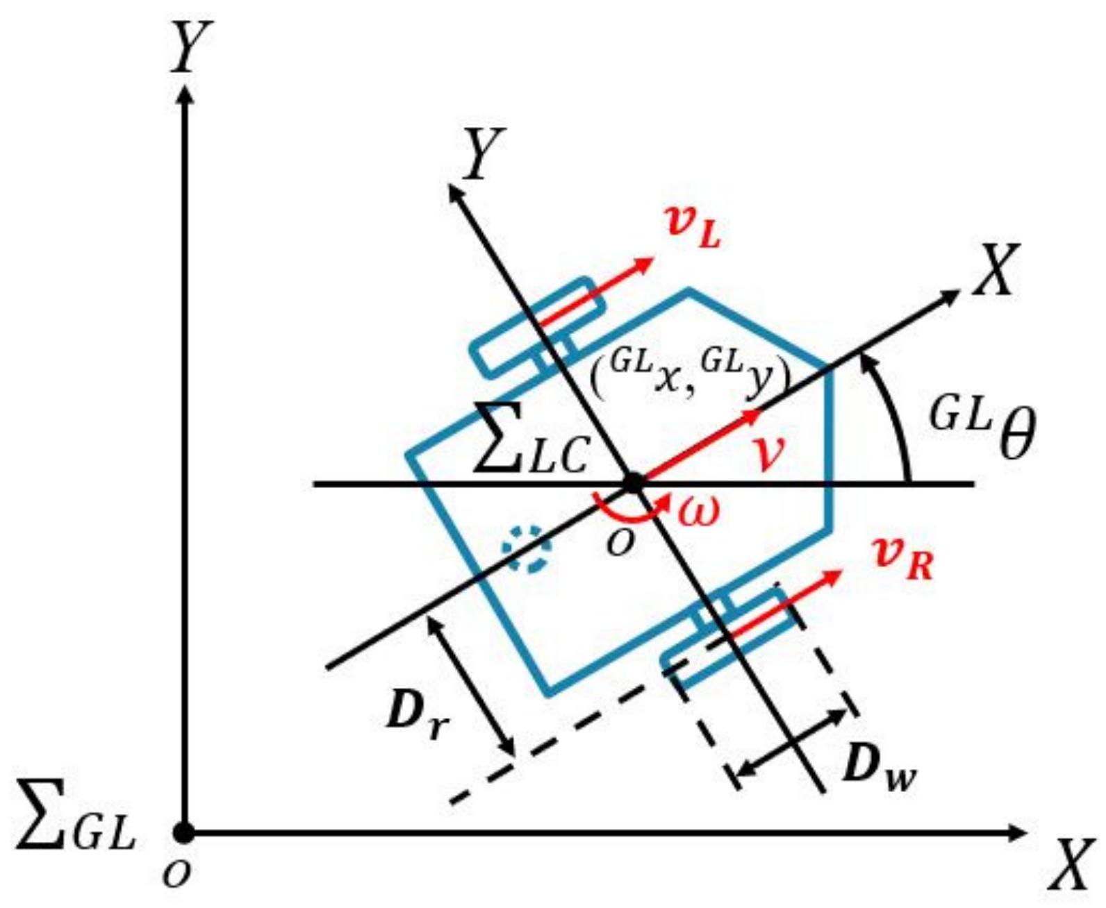
In this study, the global coordinate system and local coordinate system are defined. The origin of the local coordinate system is set at the center of the mobile robot. This center point is defined as the central point on the shaft between the wheels of the mobile robot. The origin of is set as the initial position in . The direction of the X-axis is defined as the translational velocity direction of the mobile robot when the angular velocity is 0 rad/s. The direction of the Y-axis is defined as the vertical left of the X-axis. As shown in Figure 3, (, ), and are the mobile robot positions and orientations, respectively. In this study, represents the values of the global coordinate system. The superscript is not utilized as the values are in the local coordinate system. The values of each velocity are expressed in a red color. and are the half width of the mobile robot and the diameter of each wheel. Each wheel velocity is generated through calculating the pseudo-differential by using values for each wheel angle measured by the encoder. In this article, it is assumed that the mobile robot is not sliding. The right side and left side wheel velocities, and , are calculated as follows:
where and are right side and left side wheel angles. The translational and angular velocities of the mobile robot are calculated considering with the width of the mobile robot.
v and are the translational and angular velocities of the mobile robot, respectively. The mobile robot position (, ) and orientation after t s are as follows:
2.3. Velocity Command Generator
The translational and angular velocity commands are shown as and , and are calculated from the linear movement of the control device against the initial position of the control device.
where and are the maximum values of translational and angular velocities, respectively. These values were determined from the mobile robot specifications. and represent the translational and angular positions of the linear motors, respectively. Superscripts and denote the command and response values. denotes the maximum displacement of the linear motor. The UDP sends translational and angular velocity commands to the mobile robot.
2.4. Force Controller
The mobile robot is controlled by the operator using a control device, as shown in Figure 1. Based on the possibility of collision, the operator feels force feedback as a tactile sensation from the control device. To achieve force feedback, the force controllers are implemented as Equations (10) and (11). A disturbance observer (DOB) is used for acceleration control [38]. The acceleration references are then calculated.
where and represent the acceleration references. and denote the force commands along the translational and angular velocities, respectively. and represent the reaction forces estimated using the reaction force observer (RFOB) [39]. denotes the force feedback gain. By utilizing Equations (10) and (11), the possibility of collision makes the operator feel the tactile sensation when force commands are generated. However, the operator manipulates the control device with a small operational force when the force command is set to 0 N.
2.5. Camera Coordinate Transformation
To draw trajectories on the monitor, the 3D environmental information is collected by a camera equipped on the mobile robot. The coordinates transformed from the camera coordinates to the monitor coordinates are used for the visual assist.
Figure 4 shows an image of the coordinate transformation from the camera coordinates to the monitor coordinates. Superscripts and are the mean values in the camera and monitor coordinates. The origin of the camera coordinate system is defined as the position of the visual sensor on the mobile robot. The Y- and Z-axis directions in the camera coordinate system are defined as vertically downward and the camera focal direction from the origin in . The origin of the monitor coordinate system is defined as the upper left edge point of the monitor. The U-axis and V-axis in the monitor coordinate system are defined as the direction of the right along the monitor and the vertical right of the U-axis, respectively. and are the center points of the monitor for the U and V axes, respectively. denotes the focal length of the camera. The origin of is set from (, ), which is located at a distance of along the Z-axis from the origin in . , , and are the values of point A in the camera coordinate system. and indicate the values of point in the monitor coordinate system.
The coordinate transformation from the camera coordinate system to the monitor coordinate system is achieved by multiplying the intrinsic parameters [40]. The intrinsic parameters K are expressed as follows.
where and are the lens distortions for each axis. Therefore, this coordinate transformation is calculated by multiplying the intrinsic parameters as follows:
2.6. Overall Remote-Controlled System
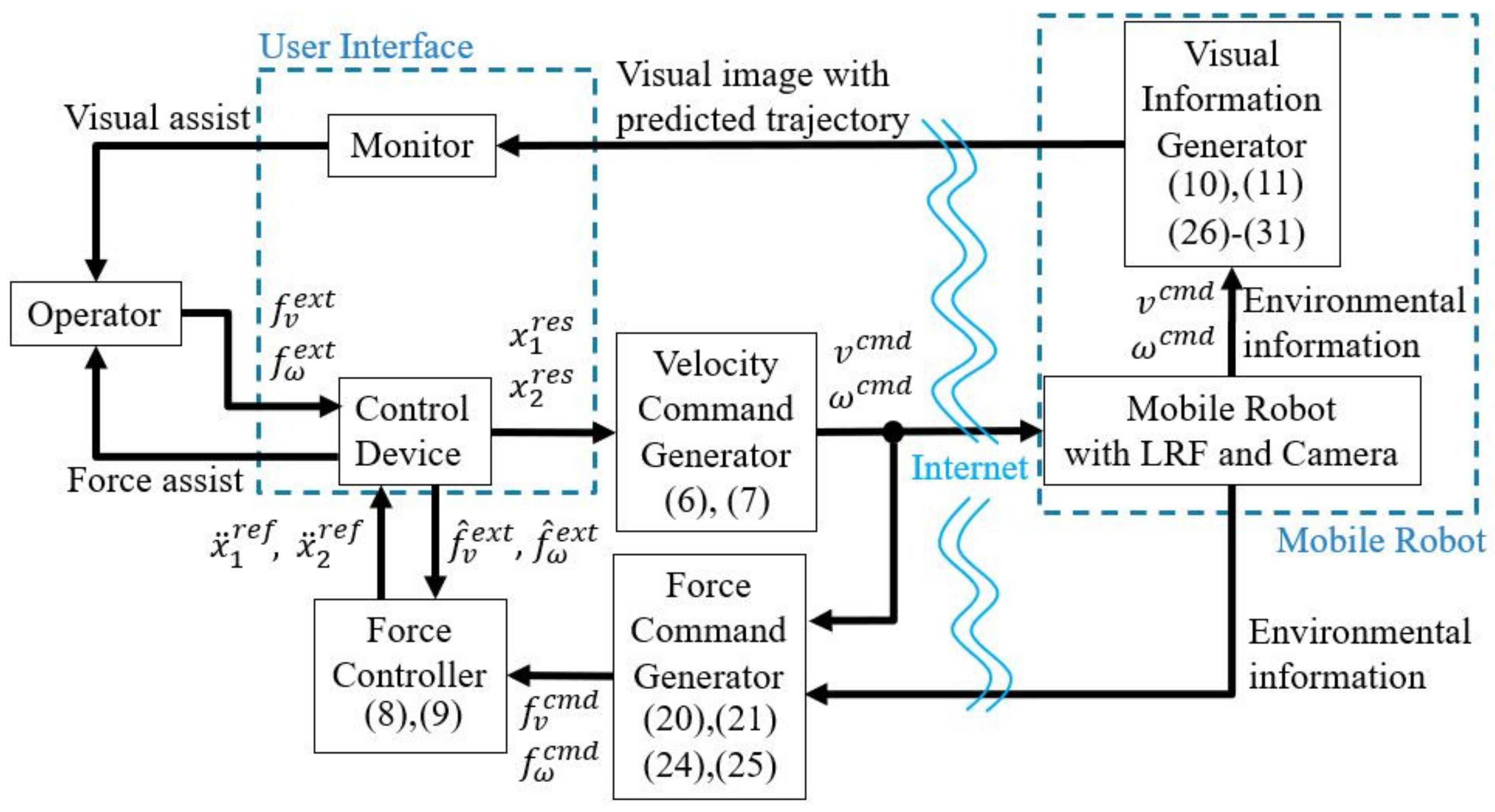
Figure 5 shows the overall remote-controlled system. In “Control Device”, the position responses of the linear motors and are calculated by the forces along the translational and angular velocities from the operator. In “Velocity Command Generator”, the translational and angular velocity commands, and , are calculated to control the mobile robot. In “Mobile Robot with LRF and Camera”, the mobile robot moves according to and . The environmental information is measured by the LRF and sent to the force command generator and the visual information generator. In “Force Command Generator”, the force commands of the translational and angular velocities, and , are calculated to obtain the force assist. In “Force Controller”, the acceleration references, and , are calculated to use for the acceleration control in the control device. Force feedback is generated at the linear motors. In “Visual Information Generator”, the predicted trajectory of the mobile robot is generated to display on the monitor. In “Monitor”, the visual information is displayed on the monitor to obtain the visual assist for the operator.
3. Proposed Method
This section explains the proposed method, which involves the use of visual and force assists in improving the operability and safety performance. The next subsection describes the force assist generated by the TTC of the mobile robot against obstacles for collision avoidance. Section 3.2 shows how the visual assist on the monitor improves operability by drawing the predicted trajectory in real time. The last subsection explains the use of the remote-controlled robot with visual and force assists. In the proposed system, the visual assist is used for operability. The force assist is used to obtain safety performance while the driver is operating the mobile robot based on the TTC.
3.1. Force Assist
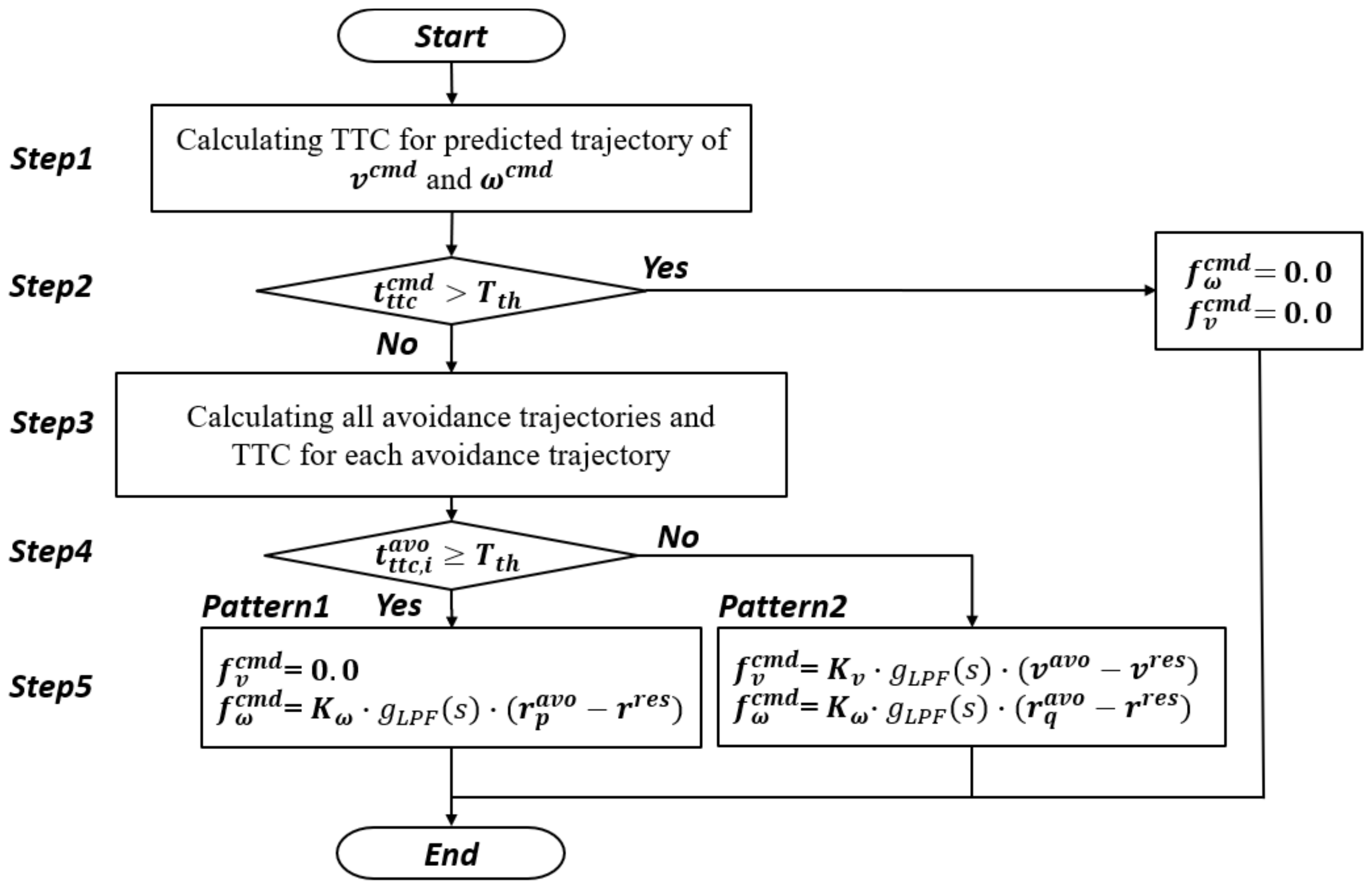
Force assist is used for collision avoidance and attaining safe performance. This subsection explains the remote-controlled method with force assist based on TTC [27]. This force assist is divided into two patterns. refers to the situation in which the mobile robot can avoid the obstacle by only assisting the angular velocity. refers to a situation in which the mobile robot cannot avoid the collision by only changing the angular velocity. Hence, it can be inferred using these situations that the mobile robot can avoid collisions by modifying not only the angular velocity but also the translational velocity. Figure 6 shows the flowchart of the force assist method from Step1 to Step5.
Step1: The mobile robot motion is assumed to be a uniform motion using the translational and angular velocity commands. The predicted trajectory is defined from the trajectory determined by this uniform motion. The closest distance from the mobile robot to the obstacle in the predicted trajectory is calculated using the turning radius as follows:
where is the angle of the closest point against the environment from the center of the turning of the mobile robot. The TTC of the predicted trajectory is calculated as follows:
where is the TTC of the predicted trajectory.
Step2: If the TTC of the predicted trajectory is larger than the time threshold for a safe operation , the force assist is not generated as it is safe. In this case, the force commands are calculated as follows:
In contrast, if TTC < , force assist is generated to avoid collisions. Step2 goes to Step3 to generate force commands.
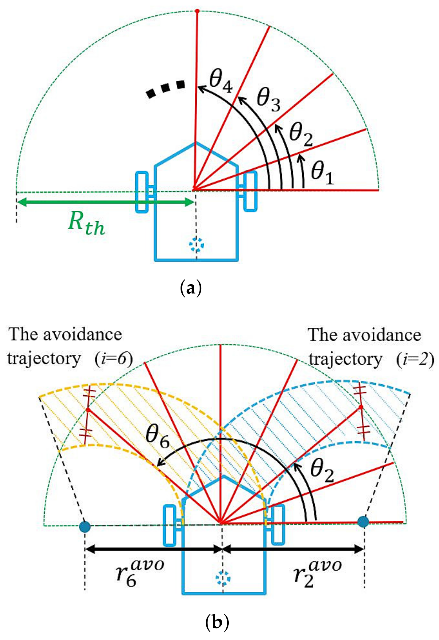
Step3: The avoidance trajectories are calculated by assuming the uniform motion of the mobile robot. All the TTC values for each avoidance trajectories are calculated. The avoidance turning radius for the angular velocity is derived from the angle , as shown in Figure 7. The ith angle of each avoidance trajectory is generated as follows:
where P denotes the number of avoidance trajectories and i denotes the coefficient. Furthermore, the avoidance turning radius for the angular velocity and each avoidance angular velocity are calculated as follows:
where indicates the turning radius for the operating range, as shown in Figure 7a. Using Equation (20), the avoidance trajectories are generated by assuming uniform motion of the mobile robot. Figure 7b shows the avoidance trajectories and at and . The shaded area in the avoidance trajectories in Figure 7b indicates a high collision probability.
Step4: The TTC for each avoidance trajectory is calculated using Equation (21) and . is compared with . Hence, if is larger than or equal to , the mobile robot achieves collision avoidance by amending only the angular velocity as . In contrast, if is less than , the mobile robot avoids the collision by amending and as .
Step5: The force commands in Pattern1 are generated as follows:
where is the force feedback gain for the angular velocity. and s are the cut-off gains of the LPF and Laplace operators, respectively. p is a coefficient j that meets .
In contrast, the force commands in Pattern2 are generated by modifying the translational velocity from to achieve a TTC that is equal to as follows:
where j is set to q, which is one of the coefficients j meeting . is the force feedback gain for the translational velocity.
3.2. Visual Assist
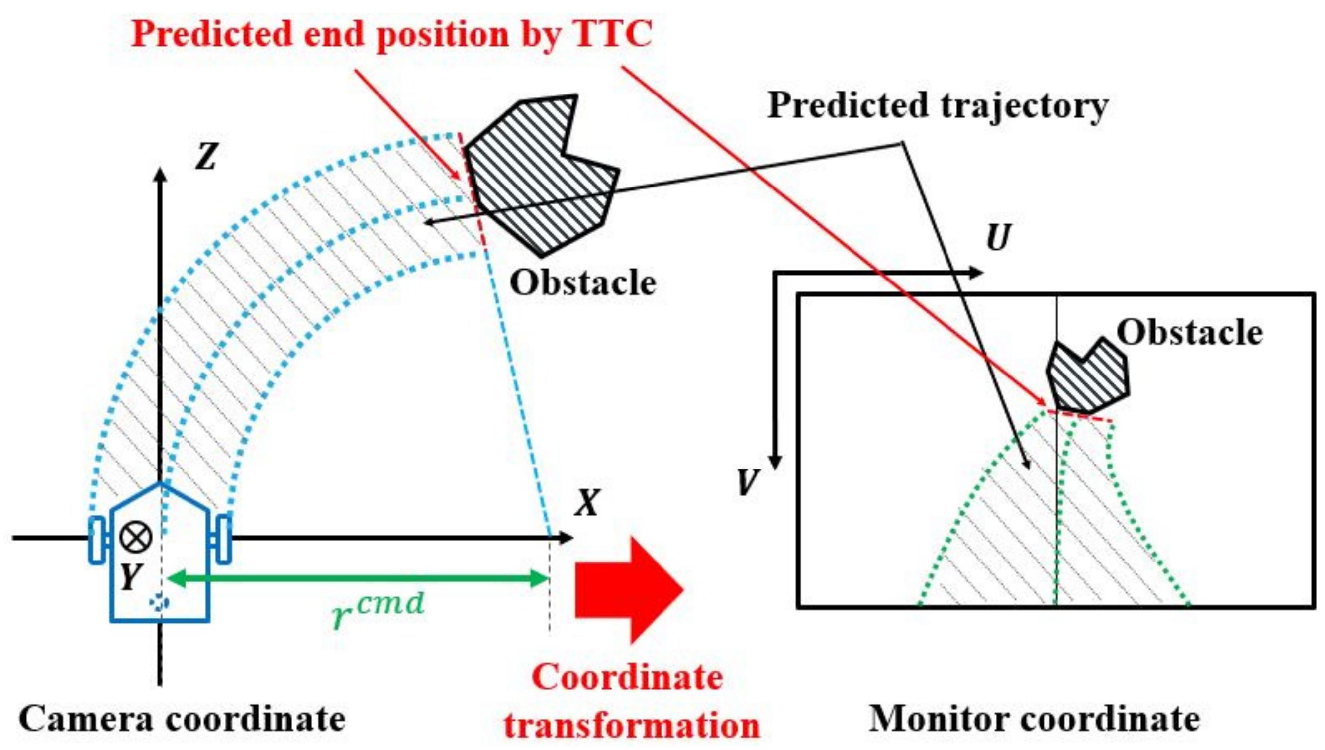
A visual assist is used for detecting the trajectories of the mobile robot while the driver is checking the monitor. The predicted trajectory on the monitor is generated by transforming the coordinates from the camera coordinates to the monitor coordinates. On the camera coordinate, the predicted trajectory is drawn using , , and with regard to the TTC, as shown in Figure 8.
This predicted trajectory is drawn from the mobile robot to the predicted end position after the TTC, assuming uniform motion of the mobile robot. The maximum TTC is set by the user as . If the TTC exceeds , the predicted end position is set to the position after . The predicted trajectory of the mobile robot is represented by the dots. The kth positions for each dot of the predicted trajectory , , and are determined using the circle equation. k is the coefficient for each dot. is the number of dots determined by the TTC between the mobile robot and obstacle.
In addition, as shown in Figure 8, the coordinate transformation is expressed using Equation (13). The color of the predicted trajectory is used as a gradation color to support remote-controlled operation. The details of this gradation color are explained later in this paper.
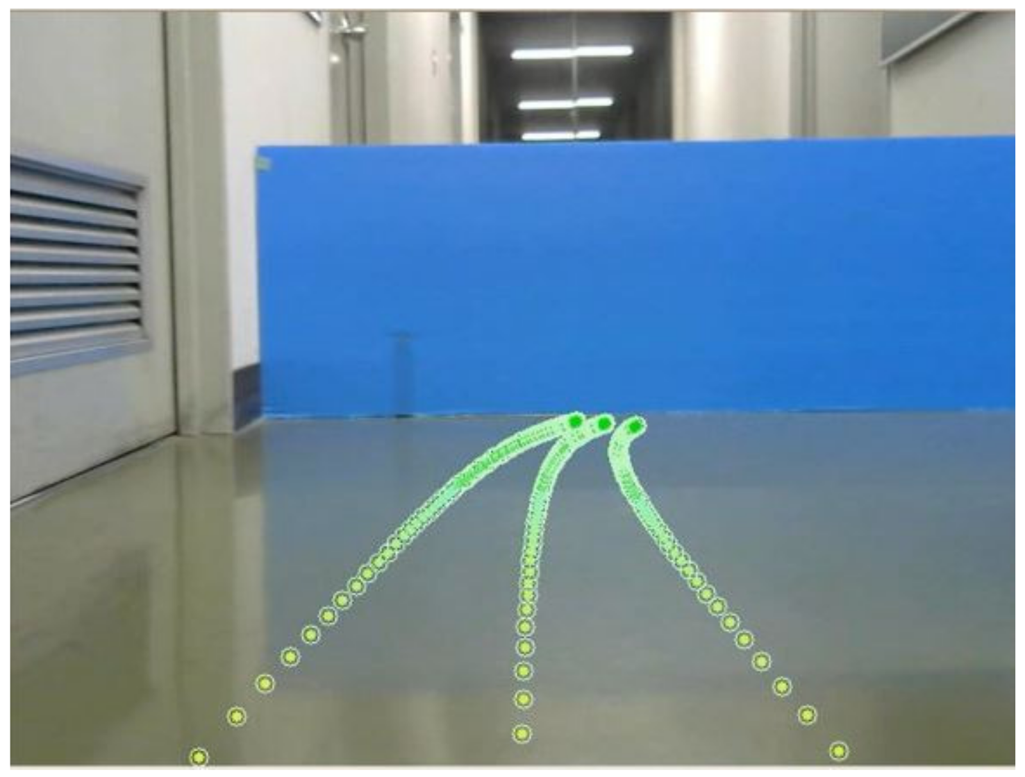
Figure 9 shows an example of the predicted trajectory on the monitor. The blue wall is an obstacle. The gradation of the dots is expressed by the colors between green and yellow. The three lines consist of dots for the predicted trajectory. These lines are generated from the lines on the camera coordinates using Equation (28). The center line expresses the center position of the mobile robot. Both side lines indicate the edges of the mobile robot and is taken as the width.
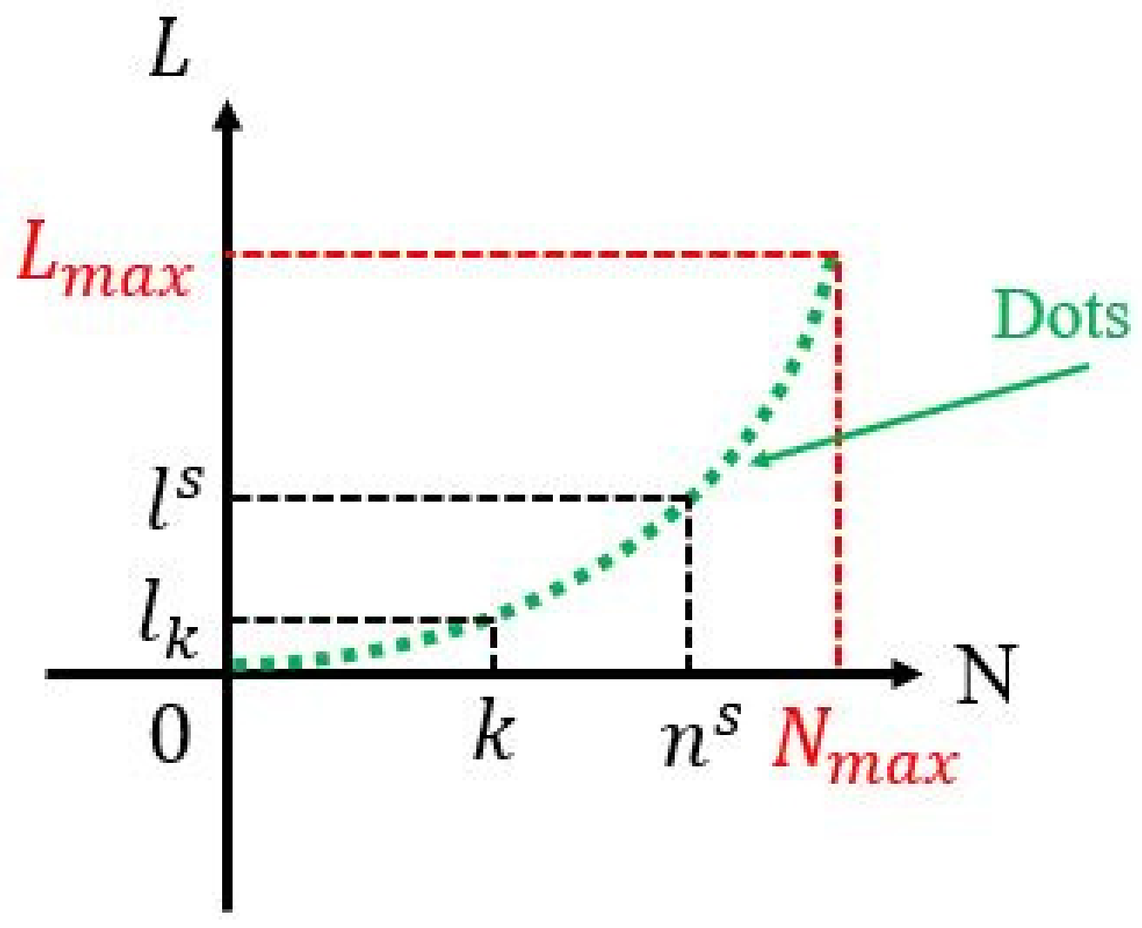
As shown in Figure 10, the distance from the mobile robot to the obstacle is used to thin dots using a quadratic function. L and N are the axes of the distance from the mobile robot to the obstacle and the number of dots, respectively. is calculated using Equation (15). represents the maximum number of dots determined from the user setting. The number of dots determined by the TTC between the mobile robot and obstacle is calculated as follows:
where is the ceiling function that assigns the smallest integer greater than or equal to each real number. is the maximum distance of the trajectory from the mobile robot. The angular velocity of the mobile robot does not exceed the value. The distance of each dot from the mobile robot is calculated as follows:
where k is the coefficient of each dot.
3.3. Force and Visual Assists
In this subsection, the proposed remote-controlled method with visual and force assists is shown. The visual assist is applied to improve the operability of the driver, and the force assist is used to obtain safe performance. When the time to collision is less than , the force assist is applied to the control device to ensure safe performance and collision avoidance.
Furthermore, the presence of the force assist is an important factor in the operability of the proposed method. This is because an excessive force assist obstructs the operation of the remote-controlled robot. The visual assist exhibits the same phenomenon. An excessive visual assist distracts the operator. Therefore, an appropriate amount of force and visual assists is necessary for improving operability.
The color gradation is set to enhance the visual assist by considering the presence of the force assist. However, it is necessary to avoid distracting the operator by using a strong color or solid line [34]. The green color is set to indicate a normal trajectory without the force assist. The yellow color is used to express attention to the force assist. The color of the dots is chosen as gradations, keeping in mind the need to indicate the degree of possibility of collision and to avoid distractions for the operator. A green color means “go” and “safety” whereas a yellow color expresses “danger” and “caution” [41]. A gradation is applied to connect the two colors. If the possibility of collision depending on the TTC becomes high-risk, the green color gradually changes to a yellow color, as shown in Figure 9. Each color is indicated by red, green, and blue (RGB) intensities for generating the gradation. In addition, color gradation is generated by . The RGB intensities of the gradation are expressed as follows:
where , , and are the intensities of green, blue, and red at the kth dot of the predicted trajectory, respectively. and are the color gains of gradation that decrease the intensity value and increase the intensity value. is the resolution gain of the gradation.
4. Experiment
This section shows the experimental results to evaluate the proposed method.
4.1. Experimental Setup
The specifications in this study that were decided based on the specifications of the mobile robot are shown in Table 1. The control parameters chosen by trial and error are listed in Table 2. In this experiment, 10 subjects who were not well acquainted with the operation of the mobile robot were dealt with.
For exhibiting operability improvement, 10 subjects (A–J) with an average age of 22.5 years and a 0.81 year standard deviation took part in the experiments. The presence of the force assist depends on . There were four different types of remote-controlled experiments:
- Case 1: Without force and visual assists;
- Case 2: With visual assist;
- Case 3: With force and visual assists with high presence of force assist ( s);
- Case 4: With force and visual assists with low presence of force assist ( s).
The mobile robot was manipulated by the subjects who were notified as to which methods were applied before the operation. However, the order of the experiments was randomly selected to avoid experience of the operation. Before starting the experiments, the subjects were permitted to practice the operation of the mobile robot.
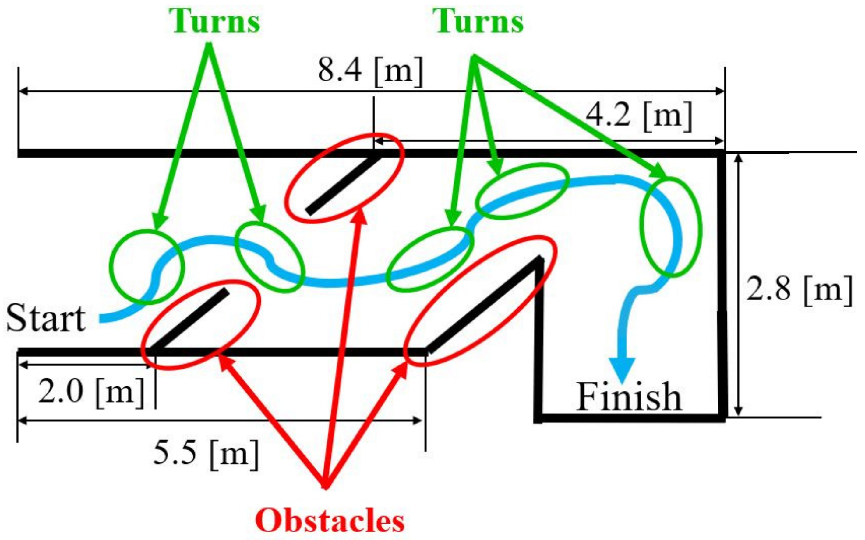
To evaluate operability, the subjects needed to achieve straight and curved operations. Therefore, as shown in Figure 11, the mobile robot moved in the clockwise direction with some obstacles. Furthermore, the experimental environment was set with at least three obstacles and five turns as an initial setting. From start to finish, the subjects were required to operate the mobile robot by achieving collision avoidance. Visual information on the monitor was used by each subject to manipulate the mobile robot.
The experimental results were evaluated with three comparisons:
- Comparison between Case 1 and Case 2 for evaluating the visual assist;
- Comparison between Case 3 and Case 4 for evaluating the presence of force assist;
- Comparison between Case 2 and Case 4 for evaluating the force and visual assists.
4.2. Experimental Results
The experiments included three different results:
- Time from start to finish;
- Number of times translational velocity fell below m/s;
- Number of collisions.
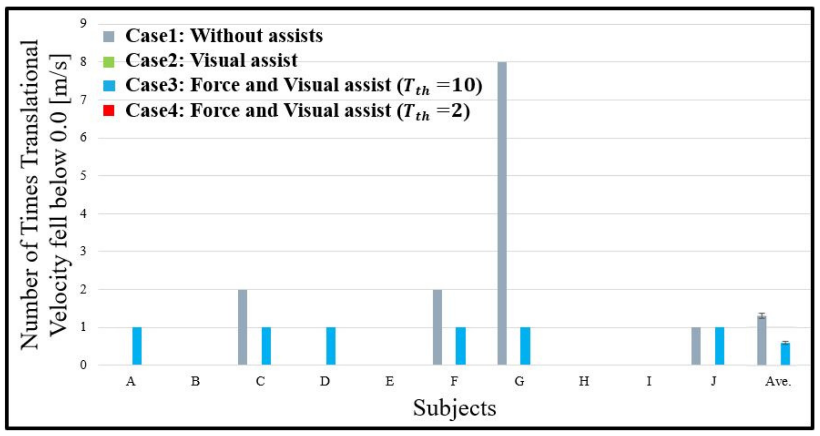
The time from start to finish and the number of times translational velocity fell below m/s evaluated the operability. In addition, the number of collisions estimated the safety performance. The number of times the translational velocity fell below m/s indicated the back operation of the mobile robot. The improvement in operability can be confirmed if the time from start to finish is short. In addition, if the number of times the translational velocity fell below m/s is less, this indicates improvement in operability. If the number of collisions is low, the safety performance can be considered to have improved.
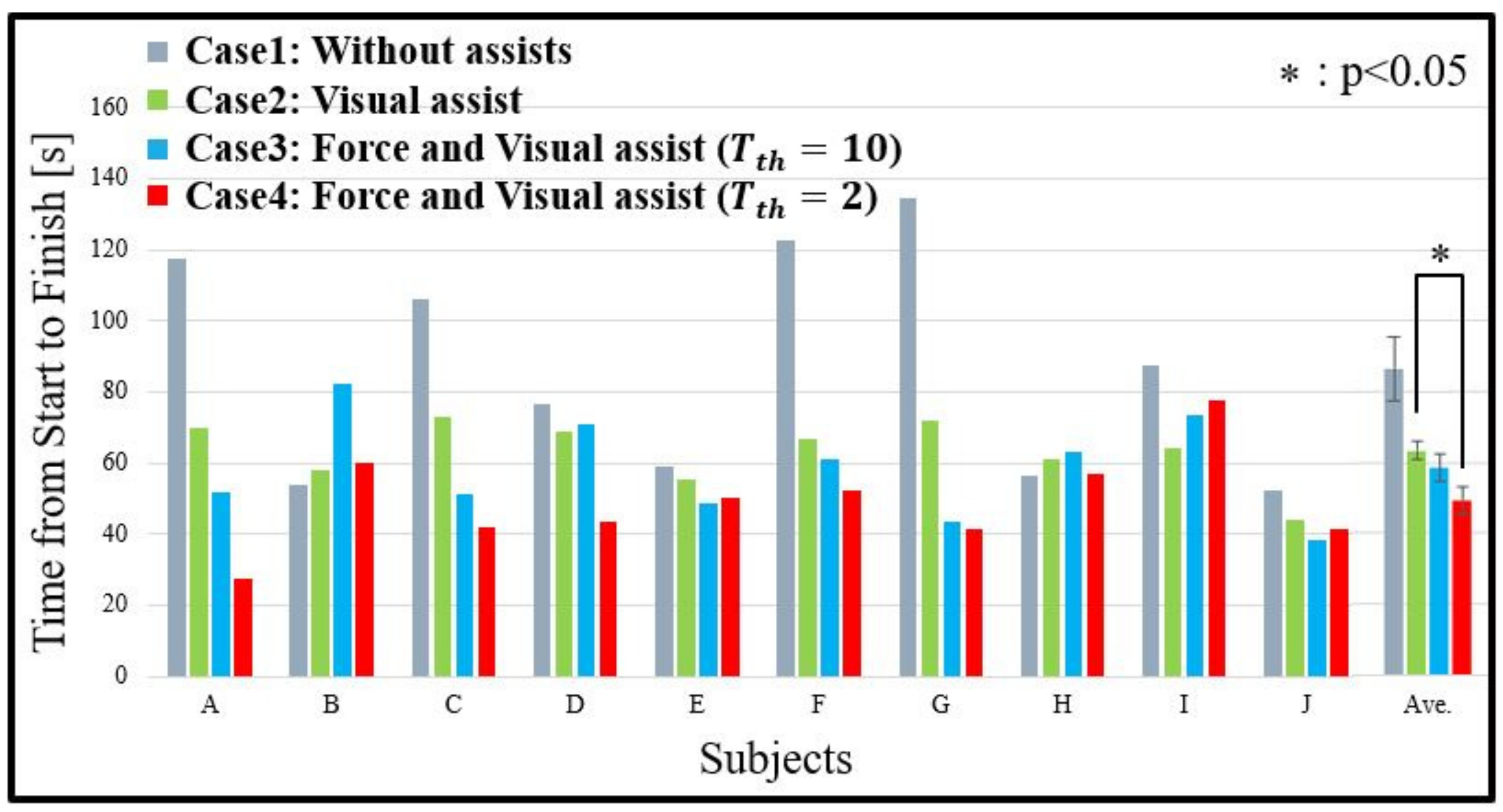
As shown in Figure 12, Figure 13 and Figure 14, the experimental results, which include all the subjects’ results, are expressed. Figure 12 shows the time from start to finish. Figure 13 shows the number of times the translational velocity fell below m/s. Figure 14 shows the number of collisions. In this study, a paired t-test was conducted for the experimental results. In Figure 12, * indicates that there is a statistically significant difference and a significance of . In Figure 12, Figure 13 and Figure 14, the distribution of data is expressed by the error bars, and a significant difference over the factor environment or support is indicated by the horizontal bars.
4.2.1. Comparison between Case 1 and Case 2 for Evaluating the Visual Assist
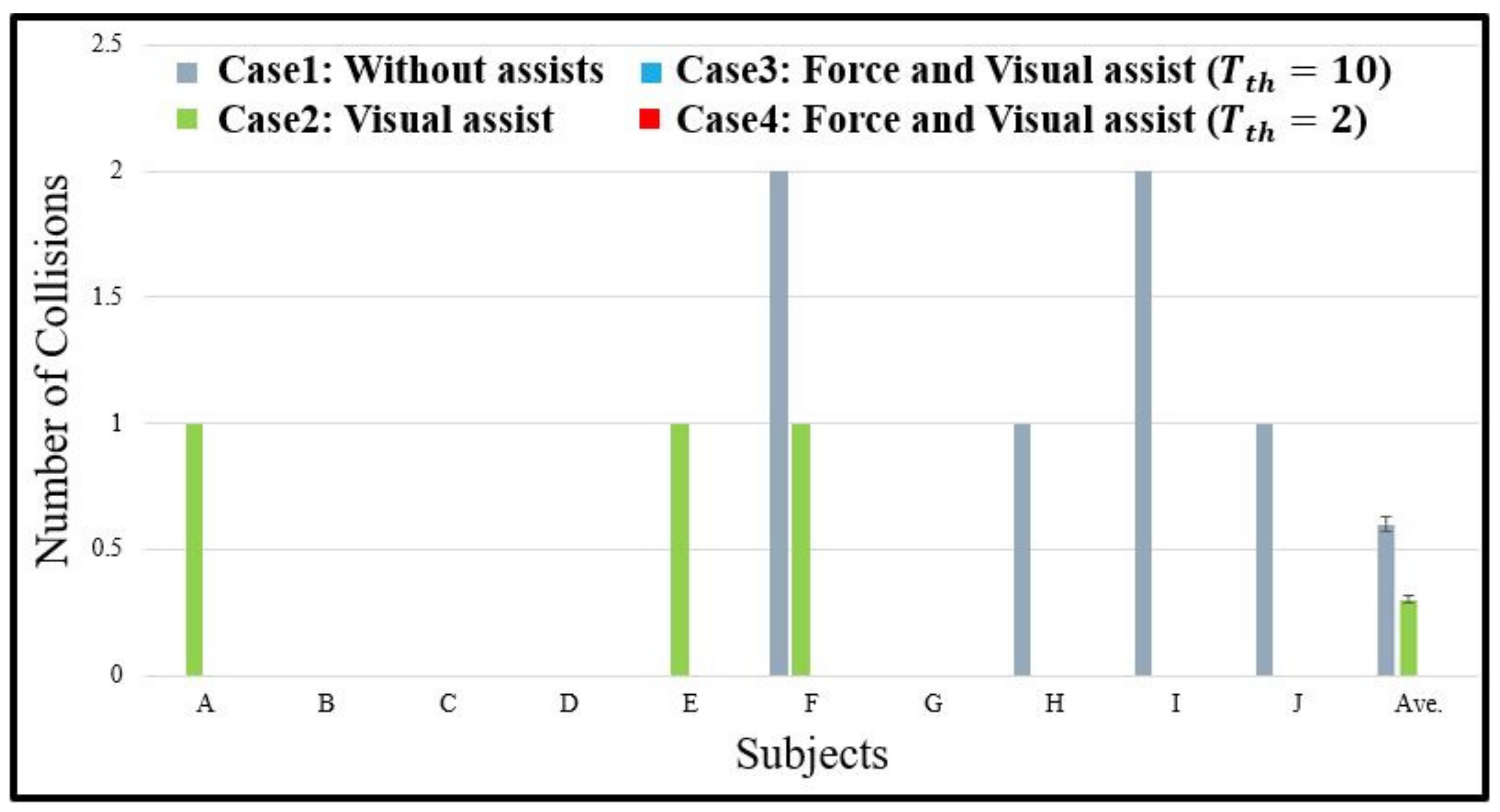
In Figure 12, for 8 out of 10 subjects, Case 2 exhibited improvement in the operability compared to Case 1. As shown in Figure 13, Case 2 exhibited improvement in the operability compared to Case 1 for subjects C, F, G, and J. However, Figure 14 does not show an improvement in the safety performance of Case 2 compared to Case 1 because there were collisions in Case 2 for subjects A, E, and F.
Figure 12.
Experimental results of time from start to finish.

Figure 13.
Experimental results of number of times translational velocity fell below m/s.

Figure 14.
Experimental results of number of collisions.

4.2.2. Comparison between Case 3 and Case 4 for Evaluating the Presence of Force Assist
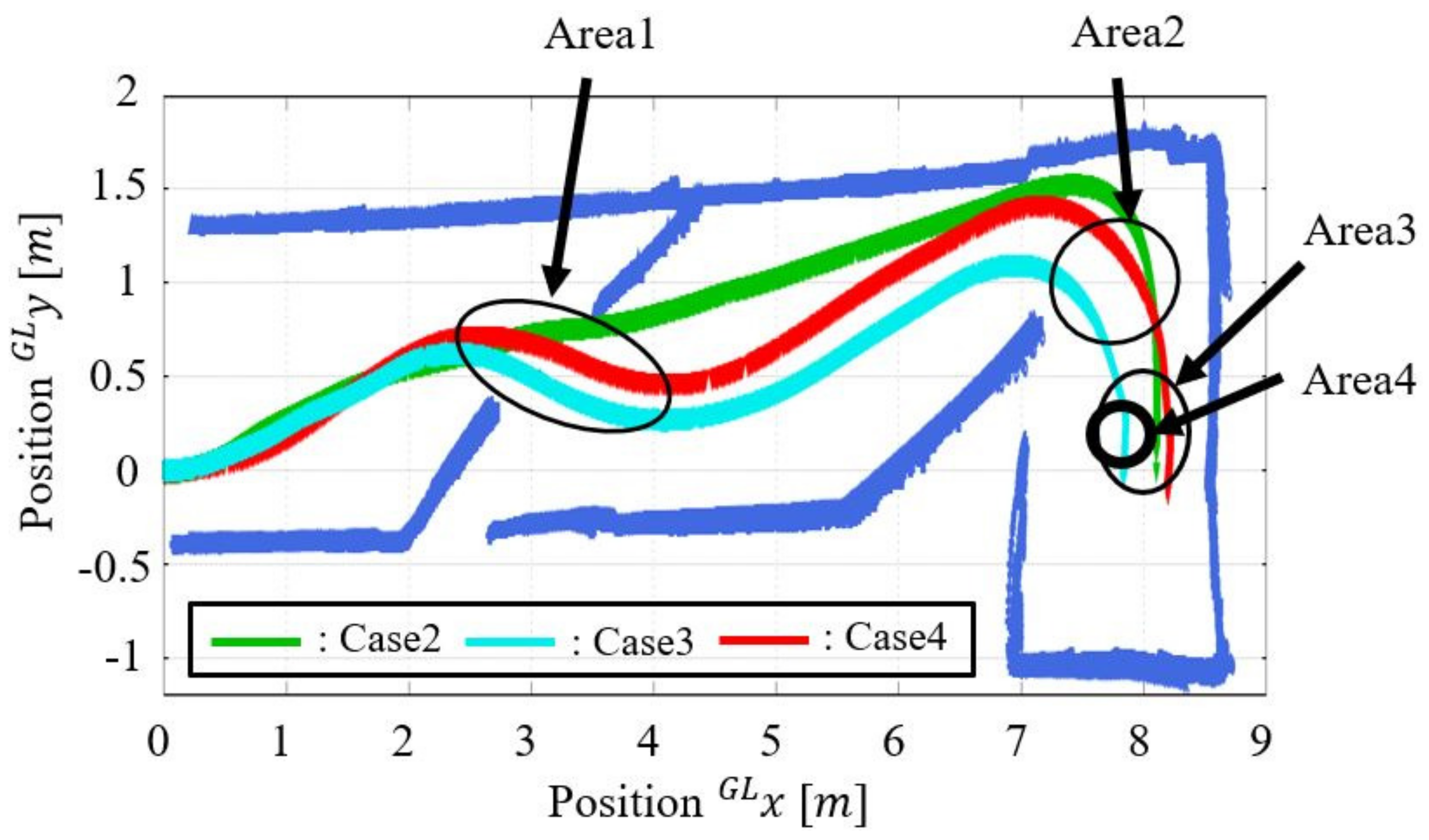
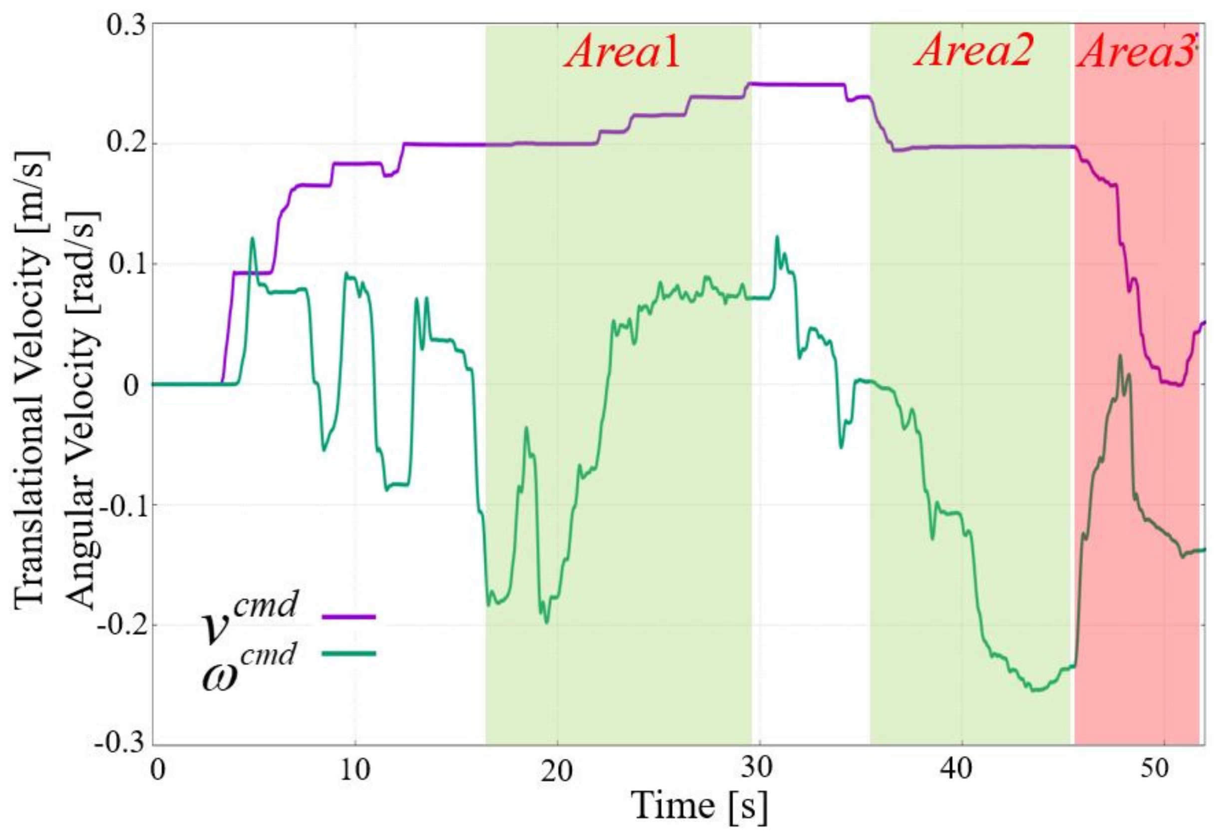
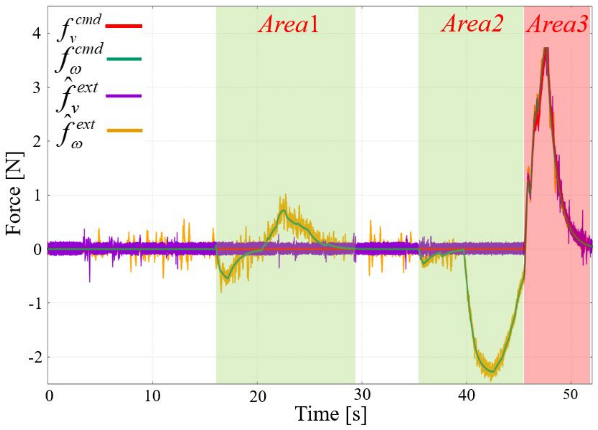
Figure 15 shows the experimental trajectories of subject A. The translational and angular velocities of Case 3 are shown in Figure 16. In addition, the experimental results of the force commands and the time to collision of the force assist are shown in Figure 17 and Figure 18. As shown in Figure 16, Figure 17 and Figure 18, the parts with light green and light red hatching, in which the force assist applied Pattern1 and Pattern2 are indicated by Area1, Area2, and Area3 in Figure 15, respectively. Similarly, the experimental results of the velocity, force commands, and time to collision for Case 4 are shown in Figure 19, Figure 20 and Figure 21.
As shown in Figure 16, Figure 17 and Figure 18, Pattern1 of the force assist in Case 3 was generated at Area1 and Area2 when the TTC was lower than . The translational and angular velocity commands of Case 3 were changed because of the force assist. Hence, as shown in Figure 15, the trajectory of Case 3 is curved more deeply to the right side than the trajectory of Case 4 against the obstacle on the left side at Area1 and Area2. At Area3, Pattern2 of the force assist was applied to the control device before arriving at the goal position, and the mobile robot was operated in back operation. The high presence of the force assist caused the back operation at Area4 in Figure 15. In contrast, as shown in Figure 19, Figure 20 and Figure 21, Pattern1 of the force assist of Case 4 was generated at Area3 when the TTC was lower than . The angular velocity command of Case 4 changed because of the force assist, whereas the translational velocity command was not modified. Hence, as shown in Figure 15, the trajectory of Case 4 is positioned closer to the goal position than the Case 3 trajectory at Area3. Around the goal position, the mobile robot in Case 4 could finish the course without back operation compared to the Case 3 trajectory.
Furthermore, as shown in Figure 12, Case 4 of the force assist improved the operability compared to Case 3, for 7 out of 10 subjects. As shown in Figure 13, Case 4 did not cause the back operation of the mobile robot for any of the subjects. Therefore, the proposed method of Case 4 improved the operability compared to Case 3 while maintaining the safety performance.
4.2.3. Comparison between Case 2 and Case 4 for Evaluating the Force and Visual Assists
For Case 4 in Figure 12, the force assist was not applied to subjects B, C, D, E, F, G, and H during the operation by the operator. Hence, the situation of Case 4 for the operator was the same as that of Case 2 during the operation. However, there was a statistically significant difference between Case 2 and Case 4. This is because the operators might have been conscious of the force assist during the operation of the mobile robot. For instance, as shown in Figure 15, the trajectory of Case 4 around Area1 is positioned farther from the left side wall from the mobile robot moving direction than the Case 2 trajectories. As shown in Figure 14, Case 2 had a collision around Area1. In addition, Case 4 improved the operability compared to Case 2 with respect to the force assist difference, for 7 out of 10 subjects, as shown in Figure 12. In Figure 13 and Figure 14, Case 4 did not cause back operation and collisions for all subjects. In summary, the method proposed for Case 4 improved the operability compared to Case 2. In addition, safe performance was achieved in Case 4 compared to Case 2.
Therefore, the method proposed for Case 4 was found to have improved the operability and safety performance, when compared to the methods proposed for Case 2 and Case 3. The authentication of the proposed method was confirmed.
5. Conclusions
In this paper we proposed a remote-controlled method with force and visual assists for a mobile robot. The visual assist was used to improve operability, and the force assist was used for safety performance. The force and visual assists could help the operator avoid collisions and maintain remote-controlled operability. The force assist was generated based on the TTC of the mobile robot against an obstacle. For collision avoidance, this force assist was applied to the operator via a control device. The predicted trajectory of the mobile robot was generated based on the TTC as a visual assist. The predicted trajectory with color gradation was provided on the monitor to improve operability. Ten subjects participated in the experiments to evaluate operability and safety performance. In summary, the proposed method, which comprised force and visual assists for a mobile robot with a low presence of the force assist, was evaluated experimentally and its validity was confirmed.
Author Contributions
Conceptualization, R.M.; methodology, R.M.; software, R.M.; validation, R.M.; formal analysis, R.M.; investigation, R.M.; resources, R.M.; data curation, R.M.; writing—original draft preparation, R.M. and M.K.; writing—review and editing, R.M. and M.K.; visualization, R.M.; supervision, N.M.; project administration, N.M.; funding acquisition, N.M. All authors have read and agreed to the published version of the manuscript.
Funding
This research was partially supported by JSPS KAKENHI (19K04454), and International Affairs Special Funding from the Graduate School of Maritime Sciences, Kobe University.
Institutional Review Board Statement
Not applicable.
Informed Consent Statement
Not applicable.
Conflicts of Interest
The authors declare no conflict of interest.
Abbreviations
The following abbreviations are used in this manuscript:
| TTC | Time to collision |
| LRF | Laser range finder |
| UDP | User datagram protocol |
| DOB | Disturbance observer |
| RFOB | Reaction force observer |
| LPF | Low-pass filter |
| RGB | Red, green, and blue |
References
- Yi, J.-B.; Kang, T.; Song, D.; Yi, S.-J. Unified Software Platform for Intelligent Home Service Robots. Appl. Sci. 2020, 10, 5874. [Google Scholar] [CrossRef]
- Ramalingam, B.; Elara Mohan, R.; Balakrishnan, S.; Elangovan, K.; Félix Gómez, B.; Pathmakumar, T.; Devarassu, M.; Mohan Rayaguru, M.; Baskar, C. sTetro-Deep Learning Powered Staircase Cleaning and Maintenance Reconfigurable Robot. Sensors 2021, 21, 6279. [Google Scholar] [CrossRef] [PubMed]
- Joon, A.; Kowalczyk, W. Design of Autonomous Mobile Robot for Cleaning in the Environment with Obstacles. Appl. Sci. 2021, 11, 8076. [Google Scholar] [CrossRef]
- Ruan, K.; Wu, Z.; Xu, Q. Smart Cleaner: A New Autonomous Indoor Disinfection Robot for Combating the COVID-19 Pandemic. Robotics 2021, 10, 87. [Google Scholar] [CrossRef]
- Dworakowski, D.; Thompson, C.; Pham-Hung, M.; Nejat, G. A Robot Architecture Using ContextSLAM to Find Products in Unknown Crowded Retail Environments. Robotics 2021, 10, 110. [Google Scholar] [CrossRef]
- Kim, H.; Choi, Y. Autonomous Driving Robot That Drives and Returns along a Planned Route in Underground Mines by Recognizing Road Signs. Appl. Sci. 2021, 11, 10235. [Google Scholar] [CrossRef]
- Skoczeń, M.; Ochman, M.; Spyra, K.; Nikodem, M.; Krata, D.; Panek, M.; Pawłowski, A. Obstacle Detection System for Agricultural Mobile Robot Application Using RGB-D Cameras. Sensors 2021, 21, 5292. [Google Scholar] [CrossRef]
- Wright, T.; West, A.; Licata, M.; Hawes, N.; Lennox, B. Simulating Ionising Radiation in Gazebo for Robotic Nuclear Inspection Challenges. Robotics 2021, 10, 86. [Google Scholar] [CrossRef]
- Wang, S.; Wang, L.; He, X.; Cao, Y. A Monocular Vision Obstacle Avoidance Method Applied to Indoor Tracking Robot. Drones 2021, 5, 105. [Google Scholar] [CrossRef]
- Shamsfakhr, F.; Motroni, A.; Palopoli, L.; Buffi, A.; Nepa, P.; Fontanelli, D. Robot Localisation Using UHF-RFID Tags: A Kalman Smoother Approach. Sensors 2021, 21, 717. [Google Scholar] [CrossRef]
- Filipescu, A.; Ionescu, D.; Filipescu, A.; Mincă, E.; Simion, G. Multifunctional Technology of Flexible Manufacturing on a Mechatronics Line with IRM and CAS, Ready for Industry 4.0. Processes 2021, 9, 864. [Google Scholar] [CrossRef]
- Zheng, Y.; Brudnak, J.M.; Jayakumar, P.; Stein, L.J.; Ersal, T. Evaluation of a Predictor-Based Framework in High-Speed Teleoperated Military UGVs. IEEE Trans. Hum.-Mach. Syst. 2020, 50, 561–572. [Google Scholar] [CrossRef]
- Zhu, S.; Xiong, G.; Chen, H.; Gong, J. Guidance Point Generation-Based Cooperative UGV Teleoperation in Unstructured Environment. Sensors 2021, 21, 2323. [Google Scholar] [CrossRef] [PubMed]
- Tsunoda, M.; Premachandra, C. Remote Control of a Wheeled Robot by Visible Light for Support in Infectious Disease Hospitals. IEEE Access 2021, 9, 124165–124175. [Google Scholar] [CrossRef]
- Paparizos, C.; Tsafas, N.; Birbas, M. A Zynq-Based Robotic System for Treatment of Contagious Diseases in Hospital Isolated Environment. Technologies 2020, 8, 28. [Google Scholar] [CrossRef]
- Barzilov, A.; Kazemeini, M. Dual-Mode Radiation Sensor for UAS Platforms. Proceedings 2020, 42, 37. [Google Scholar] [CrossRef] [Green Version]
- Sankar, S.; Tsai, C.-Y. ROS-Based Human Detection and Tracking from a Wireless Controlled Mobile Robot Using Kinect. Appl. Syst. Innov. 2019, 2, 5. [Google Scholar] [CrossRef] [Green Version]
- Pati, C.S.; Kala, R. Vision-Based Robot Following Using PID Control. Technologies 2017, 5, 34. [Google Scholar] [CrossRef] [Green Version]
- Luo, J.; Lin, Z.; Li, Y.; Yang, C. A Teleoperation Framework for Mobile Robots Based on Shared Control. IEEE Robot. Autom. Lett. 2020, 5, 2–377. [Google Scholar] [CrossRef] [Green Version]
- Clotet, E.; Martínez, D.; Moreno, J.; Tresanchez, M.; Palacín, J. Assistant Personal Robot (APR): Conception and Application of a Tele-Operated Assisted Living Robot. Sensors 2016, 16, 610. [Google Scholar] [CrossRef] [Green Version]
- Novák, P.; Kot, T.; Babjak, J.; Konečný, Z.; Moczulski, W.; Rodriguez López, Á. Implementation of Explosion Safety Regulations in Design of a Mobile Robot for Coal Mines. Appl. Sci. 2018, 8, 2300. [Google Scholar] [CrossRef] [Green Version]
- Veiga Almagro, C.; Lunghi, G.; Di Castro, M.; Centelles Beltran, D.; Marín Prades, R.; Masi, A.; Sanz, P.J. Cooperative and Multimodal Capabilities Enhancement in the CERNTAURO Human–Robot Interface for Hazardous and Underwater Scenarios. Appl. Sci. 2020, 10, 6144. [Google Scholar] [CrossRef]
- Zhao, J.; Gao, J.; Zhao, F.; Liu, Y. A Search-and-Rescue Robot System for Remotely Sensing the Underground Coal Mine Environment. Sensors 2017, 17, 2426. [Google Scholar] [CrossRef] [PubMed] [Green Version]
- Dong, Y.; Chopra, N. Passivity-Based Bilateral Tele-Driving System with Parametric Uncertainty and Communication Delays. IEEE Control Syst. Lett. 2019, 3, 350–355. [Google Scholar] [CrossRef]
- Wu, Y.; Balatti, P.; Lorenzini, M.; Zhao, F.; Kim, W.; Ajoudani, A. A Teleoperation Interface for Loco-Manipulation Control of Mobile Collaborative Robotic Assistant. IEEE Robot. Autom. Lett. 2019, 4, 3593–3600. [Google Scholar] [CrossRef] [Green Version]
- Xu, Y.; Yang, C.; Liu, X.; Li, Z. A Teleoperated Shared Control Scheme for Mobile Robot Based sEMG. In Proceedings of the 2018 3rd International Conference on Advanced Robotics and Mechatronics (ICARM), Singapore, 18–20 July 2018; pp. 288–293. [Google Scholar] [CrossRef]
- Masaki, R.; Motoi, N. Remote Control Method With Force Assist Based on Time to Collision for Mobile Robot. IEEE Open J. Ind. Electron. Soc. 2020, 1, 157–165. [Google Scholar] [CrossRef]
- Khurshid, P.R.; Fitter, T.N.; Fedalei, A.E.; Kuchenbecker, J.K. Effects of Grip-Force, Contact, and Acceleration Feedback on a Teleoperated Pick-and-Place Task. IEEE Trans. Haptics 2017, 10, 40–53. [Google Scholar] [CrossRef]
- Aggravi, M.; Pacchierotti, C.; Giordano, R.P. Connectivity-Maintenance Teleoperation of a UAV Fleet With Wearable Haptic Feedback. IEEE Trans. Autom. Sci. Eng. 2021, 18, 1243–1262. [Google Scholar] [CrossRef]
- Rute, L.; José, C.; Laurent, G.; Frédéric, G.; José, L.S.; Rodrigo, V. On the Use of Haptic Tablets for UGV Teleoperation in Unstructured Environments: System Design and Evaluation. IEEE Access 2019, 7, 95443–95454. [Google Scholar] [CrossRef]
- Chandan, K.; Xiaohan, Z.; John, D.A.; Xiaoyang, Z.; Yao, L.; Shiqi, Z. Guided 360-Degree Visual Perception for Mobile Telepresence Robots. In Proceedings of the RSS—2020 Workshop on Closing the Academia to Real-World Gap in Service Robotics, Corvallis, OR, USA, 13 July 2020. [Google Scholar]
- Chao, C.-T.; Chung, M.-H.; Chiou, J.-S.; Wang, C.-J. A Simple Interface for 3D Position Estimation of a Mobile Robot with Single Camera. Sensors 2016, 16, 435. [Google Scholar] [CrossRef] [Green Version]
- Lunghi, G.; Marin, R.; Castro, D.M.; Masi, A.; Sanz, J.P. Multimodal Human-Robot Interface for Accessible Remote Robotic Interventions in Hazardous Environments. IEEE Access 2019, 7, 127290–127319. [Google Scholar] [CrossRef]
- Kružić, S.; Musić, J.; Stančić, I. Influence of human-computer interface elements on performance of teleoperated mobile robot. In Proceedings of the 2017 40th International Convention on Information and Communication Technology Electronics and Microelectronics (MIPRO), Opatija, Croatia, 22–26 May 2017; pp. 1015–1020. [Google Scholar] [CrossRef]
- Hidaka, K.; Saito, N. Development of Operation Assist System for Remote Control of A Mobile Robot. In Proceedings of the 2018 12th France-Japan and 10th Europe-Asia Congress on Mechatronics, Tsu, Japan, 10–12 September 2018; pp. 407–410. [Google Scholar] [CrossRef]
- T-Frog Project. Available online: http://t-frog.com/ (accessed on 13 October 2021).
- HOKUYO AUTOMATIC CO., LTD. Available online: http://www.hokuyo-aut.co.jp/ (accessed on 13 October 2021).
- Ohnishi, K.; Shibata, M.; Murakami, T. Motion Control for Advanced Mechatronics. IEEE/ASME Trans. Mechatron. 1996, 1, 56–67. [Google Scholar] [CrossRef]
- Murakami, T.; Yu, F.; Ohnishi, K. Torque Sensorless Control in Multidegree-of-Freedom Manipulator. IEEE Trans. Ind. Electron 1993, 40, 259–265. [Google Scholar] [CrossRef]
- Huang, Y. A Switched Approach to Image-Based Stabilization for Nonholonomic Mobile Robots with Field-of-View Constraints. Appl. Sci. 2021, 11, 10895. [Google Scholar] [CrossRef]
- ISO22324; Societal Security—Emergency Management—Guidelines for Colour-Coded Alerts. ISO: Geneva, Switzerland, 2015. Available online: https://www.iso.org/standard/50061.html (accessed on 16 February 2022).
Figure 1.
System configuration.

Figure 2.
Control device.

Figure 3.
Mobile robot position and orientation.

Figure 4.
Image of coordinate transformation from camera coordinate to monitor coordinate.

Figure 5.
System configuration.

Figure 6.
Flowchart of force assist method.

Figure 7.
Relationship with angle and avoidance trajectory. (a) Turning radius and angle . (b) Avoidance trajectory and .
Figure 7.
Relationship with angle and avoidance trajectory. (a) Turning radius and angle . (b) Avoidance trajectory and .

Figure 8.
Predicted trajectory on the camera coordinate.

Figure 9.
Example of visual assist.

Figure 10.
Image of the allocation of dots.

Figure 11.
Experimental course.

Figure 15.
Experimental trajectories of Case 2, Case 3, and Case 4 for Subject A.

Figure 16.
Experimental results of velocity of Case 3 for Subject A.

Figure 17.
Experimental results of force commands of Case 3 for Subject A.

Figure 18.
Experimental results of time to collision of Case 3 for Subject A.

Figure 19.
Experimental results of velocity of Case 4 for Subject A.

Figure 20.
Experimental results of force commands of Case 4 for Subject A.

Figure 21.
Experimental results of time to collision of Case 4 for Subject A.


Table 1.
Specifications of mobile robot.
| Parameters | Descriptions | Values |
|---|---|---|
| Maximum translational velocity | (m/s) | |
| Minimum translational velocity | (m/s) | |
| Maximum angular velocity | (rad/s) | |
| Minimum angular velocity | (rad/s) | |
| Maximum translational acceleration | ||
| Maximum angular acceleration | ||
| Half width of mobile robot | (m) | |
| Diameter of wheel | (m) | |
| H | Height of mobile robot | (m) |
Table 2.
Control parameters.
| Parameters | Descriptions | Values |
|---|---|---|
| Translational force feedback gain | ||
| Angular force feedback gain | ||
| Collision-free operating range | (m) | |
| P | Number of trajectories for searching | 21 |
| Time threshold for safe operation | (s) (Case 3) | |
| (s) (Case 4) | ||
| Cut-off frequency of force command | (rad/s) | |
| Maximum time to collision | (s) | |
| Maximum number of dots | 50 | |
| Lens distortion for x-axis | ||
| Lens distortion for y-axis | ||
| Focal length of camera | (mm) | |
| Center point of monitor for U-axis | (px) | |
| Center point of monitor for V-axis | (px) | |
| Color gain of gradation to increase intensity | ||
| Color gain of gradation to decrease intensity | ||
| Resolution gain of gradation |
Publisher’s Note: MDPI stays neutral with regard to jurisdictional claims in published maps and institutional affiliations. |
© 2022 by the authors. Licensee MDPI, Basel, Switzerland. This article is an open access article distributed under the terms and conditions of the Creative Commons Attribution (CC BY) license (https://creativecommons.org/licenses/by/4.0/).
Share and Cite
MDPI and ACS Style
Masaki, R.; Kobayashi, M.; Motoi, N. Remote-Controlled Method with Force and Visual Assists Based on Time to Collision for Mobile Robot. Appl. Sci. 2022, 12, 3727. https://doi.org/10.3390/app12083727
AMA Style
Masaki R, Kobayashi M, Motoi N. Remote-Controlled Method with Force and Visual Assists Based on Time to Collision for Mobile Robot. Applied Sciences. 2022; 12(8):3727. https://doi.org/10.3390/app12083727
Chicago/Turabian StyleMasaki, Ryo, Masato Kobayashi, and Naoki Motoi. 2022. "Remote-Controlled Method with Force and Visual Assists Based on Time to Collision for Mobile Robot" Applied Sciences 12, no. 8: 3727. https://doi.org/10.3390/app12083727
Note that from the first issue of 2016, this journal uses article numbers instead of page numbers. See further details here.