Article

An In-Pipe Inspection Robot with Permanent Magnets and Omnidirectional Wheels: Design and Implementation

by
Kaned Thung-Od
1,
Kiattisin Kanjanawanishkul
2,*,
Thavida Maneewarn
3,
Thunyaseth Sethaput
4 and
Arsit Boonyaprapasorn
5
1
Mechatronics Research Unit, Faculty of Engineering, Mahasarakham University, Mahasarakham 44150, Thailand
2
Research Unit of Process Design and Automation, Faculty of Engineering, Mahasarakham University, Mahasarakham 44150, Thailand
3
Institute of Field Robotics, King Mongkut’s University of Technology Thonburi, Bangkok 10140, Thailand
4
Department of Mechanical Engineering, Sirindhorn International Institute of Technology, Thammasat University, Bangkok 12120, Thailand
5
Department of Mechanical Engineering, Chulachomklao Royal Military Academy, Nakhon Nayok 26001, Thailand
*
Author to whom correspondence should be addressed.
Appl. Sci. 2022, 12(3), 1226; https://doi.org/10.3390/app12031226
Submission received: 28 November 2021 / Revised: 26 December 2021 / Accepted: 12 January 2022 / Published: 25 January 2022
(This article belongs to the Section Robotics and Automation)

Abstract

:
This paper aims to present the design and prototype of an inspection robot that can perform both horizontal and vertical locomotion in ferromagnetic pipelines. The proposed robot applies to a range from 5-inch (127 mm) diameter pipes to flat plates. The train-like robot is mainly composed of three sealed modules with omnidirectional driving wheels for longitudinal and transverse movements. Permanent magnets were designed to provide sufficient magnetic adhesion between the robot and the ferromagnetic surface of the pipes. The internal condition of the pipe can be monitored visually through cameras and sensors. Specific experimental conditions have been carried out to validate the robot’s capabilities, including maximum speed, payload capacity, and vertical climbing distance. The experimental results also show that the robot is capable of passing through a straight pipe and elbow fitting in both upward and downward directions.

1. Introduction

Ferromagnetic pipelines are the primary means of transporting gas, oil, and other liquids, especially in the industrial sector. Pipeline maintenance and inspection are necessary to ensure proper functioning conditions. The manual assessment of the internal conditions of small diameter pipes by workers and/or in hazardous conditions is unfeasible. To prevent the exposure of operators to these conditions, in-pipe inspection robots could potentially replace the human-conducted tasks.
In the literature, in-pipe inspection robots are categorized into five common systems based on robotic locomotion. First, wheeled robots [1,2,3,4] have simple structural designs. These systems typically have good maneuverability and can be controlled easily. Wheeled systems are also extensively combined with other locomotion types [5]. Second, inchworm-like robots [6,7,8,9,10] can perform both horizontal and vertical locomotion, but still have difficulties in traveling along a curved pipe. Third, wall-pressed robots [11,12,13,14,15,16] are the most popular system used for the application of in-pipe inspection robots [5]. These systems require a frictional force between the leg or wheel of the robot and the inner wall of the pipe to travel along the pipe. These robots have difficulties in passing through elbow and tee connectors. Due to the structure of the wall-pressed robots, the range of accessible pipe diameters is restricted. Fourth, snake-like or train-like robots [17,18,19,20,21,22] are modular robots that have a strong adaptability to complex configurations of pipelines and fittings. However, due to the modular design, these robots may experience unreliable motion control problems. Fifth, magnetic systems [23,24,25,26,27] can be applied in vertical, horizontal, and curved ferromagnetic pipes. These systems are also applicable to a wide range of pipe sizes. Kawaguchi et al. [27] designed a robot to move in vertical pipes using 2 magnet wheels. The robot can move in both longitudinal and lateral directions by rotating the wheels, but it is difficult to control the robot to move steadily in the lateral direction.
From the literature review, our proposed in-pipe robot is inspirationally designed based on a combination of the easy-to-control characteristics of wheeled robots, the flexibility characteristics of snake-like or train-like robots, and the advantageous ability of a magnetic system that can be applied to the various sizes of ferromagnetic pipes. In this article, we present the design and implementation of an in-pipe inspection robot that is applicable to a wide range of ferromagnetic pipe sizes from 5-inch (127 mm) diameter pipes to flat plates. The proposed robot can travel in any direction and pass through 90-degree elbow fittings. The robot can also provide real-time visual feedback and operate in waterlogged conditions.

2. Design Principle

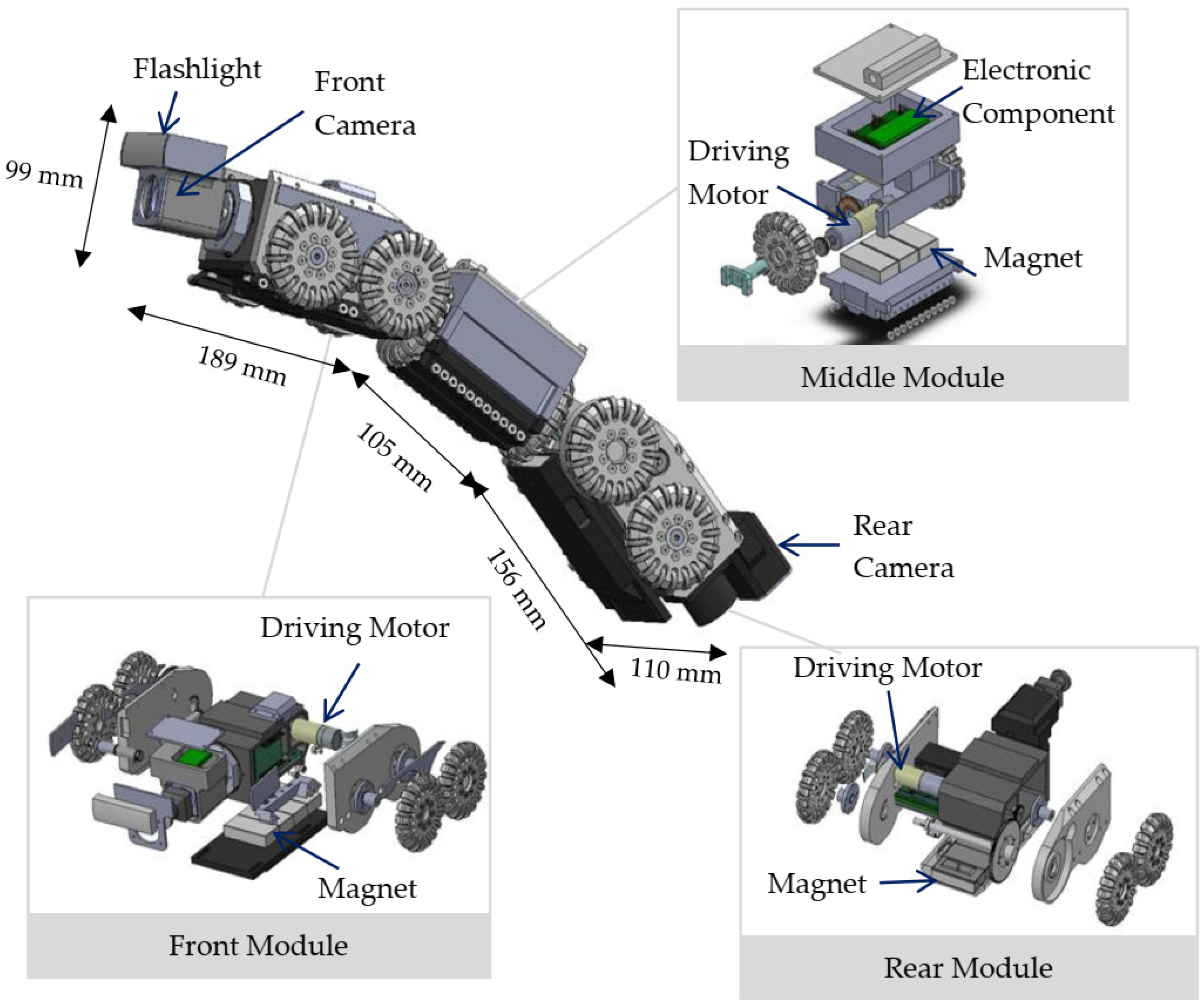
2.1. Mechanical Design and Materials

In order for the proposed in-pipe inspection robot to move inside the 5-inch (127 mm) diameter pipe, the robot was designed to be 110 mm wide, 99 mm tall, and 450 mm long. Figure 1 shows the 3D CAD model of the robot, which is mainly composed of three modules in the manner of a train with front, middle, and rear modules. The front and rear modules consist of motor-driven CCTV cameras, a flashlight for dark environments, and a powertrain system for forward–backward (longitudinal) motion. The middle module consists of electronic components and a powertrain system for transverse motions. The sealed modules provide the water-resistant ability of the robot. As shown in Figure 2, each module is connected by a passive linkage mechanism that allows the module to rotate freely. Moreover, the passive links ensure that the robot is flexible enough to move around curves and that all modules adhere to the surface all of the time. Rectangular magnets of 40 mm × 20 mm × 10 mm Neodymium (NdFeB)-N35 are used to provide the adhesive force for the robot. Four permanent magnets are located underneath the front and rear module and three magnets under the middle module.
According to the analysis in the literature, it is apparent that robots with magnetic adhesion mechanisms are competent in exploring pipelines of various sizes and configurations. However, these robots may experience difficulty in passing through curved pipes because the robots are unable to perform transverse movement around the pipeline’s curve. To solve the problem of lateral maneuverability, omnidirectional wheels were introduced to assist the permanent magnets. The omnidirectional robot wheels allow longitudinal and lateral motions. In addition, the wheels improve the maneuverability of the robot by maintaining the optimal distance between the robot and the inner wall of the pipe to stabilize the adhesive force. The driving wheels and supporting wheels are attached to the front and rear modules. Two driving wheels are attached to the middle module for the purpose of transverse movement. In the proposed robot, the omnidirectional wheels are made from aluminum with a diameter of 60 mm. As presented in Figure 3, eighteen small rubber wheels (1.2 cm diameter) are plugged into each omnidirectional wheel. The rubber wheels are mounted perpendicularly to the rotational axis of the omnidirectional wheel.

2.2. Shim Plate

Figure 4a shows the size of the robot (110 mm wide and 99 mm tall) relative to the ferromagnetic pipes of different sizes (5 to 9-inch or 127 to 228 mm diameters). When the size of the pipe changes, the distance between the magnet and the inner wall of the pipe also changes. For the magnetic adhesive force to have the desired value for different pipe diameters, a shim plate with a specific thickness is required to be mounted on the front and rear modules, as shown in Figure 4b. The suitable thickness of the shim plate for the various pipe sizes can be calculated from Equations (1) and (2) based on the parameters shown in Figure 5.
w = r t r t 2 d c 2
c = w + u h m g h
where   c is the thickness of the shim plate, r t is the radius of the pipe, d c is the distance between the center of the robot and the center of the wheel (45 mm), u is the distance between the base of the robot wheel and the lowest end of the robot body (17.4 mm), w is the distance between the base of the robot wheel and the inner wall of the pipe below the robot, h m is the thickness of the permanent magnet (13.5 mm), and g h is the distance between the lowest end of the magnet and the inner wall of the pipe below the robot.
After calculation, the suitable thickness of the shim plate for various pipe sizes is presented in Table 1. To keep the distance between the lowest end of the magnet and the inner wall of the pipe below the robot ( g h ) equal to 4 mm (see Section 2.4), a 5-inch (127 mm) diameter pipe requires an 18-mm shim plate. Table 1 also shows that larger pipe diameters require thinner shim plates to satisfy the requirement of the adhesive force.

2.3. Magnetic Adhesive System

We used the adhesive force of the permanent magnets for the vertical movement of the robot. In this subsection, the adhesive force of the permanent magnets is detailed and analyzed statically. According to [28], the magnetic force depends on the magnetic flux density ( B ), where the flux density is based on the distance between the magnet and the ferromagnetic object, the area of the magnetic pole ( A g ) , and the magnetic permeability of air or of a vacuum ( μ 0 ), which is equal to 4 π × 10 7 H/m as presented in Equation (3).
F m a g n e t = B 2 A g 2 μ 0
Figure 6 shows the simulation results of the magnetic flux distribution using Finite Element Method Magnetics (FEMM4.2). At the same distance between the magnet and the ferromagnetic objects, the results reveal that a higher magnetic flux distribution when the magnet is inside the pipe (Figure 6a) compared to that in the flat plate (Figure 6b). Due to the curvature of the pipe surface, the maximum magnetic flux distribution occurs at the edge of the magnet.
For vertical movement, the force analysis to prevent the robot from slipping is presented in Figure 7. The frictional forces at the driving wheels ( F f r i c 1 ,   F f r i c 2 ,   F f r i c 3 , and F f r i c 4 ) are related to the normal forces ( N 1 ,   N 2 ,   N 3 ,   and N 4 ) where the normal forces depend on the adhesive force of the permanent magnets ( F m a g 1 ,     F m a g 2   ,   and F m a g 3 ). The relationship can be expressed as:
N 1 = d 1 l 1 F m a g 1
N 4 = d 2 l 1 F m a g 3
N 2 = N 3 = F m a g 2 2
where   d 1 ,     l 1 ,     d 2 ,   and   l 2 are presented in Figure 7.
In order to prevent the robot from slipping or falling from a vertical surface, the magnetic adhesive forces are calculated from the formula for frictional force given by F = μ s N , where μ s is the coefficient of static friction between the robot’s wheel and the ferromagnetic surface. The sufficient frictional force can be obtained as follows:
F f r i c 1 = μ s d 1 l 1 F m a g 1
F f r i c 2 = μ s d 2 l 2 F m a g 3
F f r i c 3 = F f r i c 4 = μ s F m a g 2 2
When the robot is in vertical motion, it is loaded by the robot’s weight ( G r o b o t ) and the increment in the length of the control cable ( G c a b l e ). The gravitational force due to the control cable’s weight can be expressed as:
G c a b l e = 9.8 ( A m l + m s l i p r i n g + c o n n e c t o r )
where A m is the ratio of the weight of the control cable per unit length, l is the length of the control cable from the robot to the ground, and m s l i p r i n g + c o n n e c t o r is the mass of the slip ring and connector. Hence, the frictional force needed to oppose slipping or sliding along the contact surface is required to be greater than the loads of the robot and the control cable, which can be expressed as follows:
μ s d 1 l 1 F m a g 1 + μ s d 2 l 2 F m a g 3 ( G r o b o t + G c a b l e ) sin θ
μ s F m a g 2 G r o b o t cos θ

2.4. Motor Power

The calculation for the motor power of this proposed robot is based on the vertical mobility of the robot because this is the stage that the robot requires its maximum load capacity. While the robot is in vertical motion, the required driving force ( F r e q ) for the robot is presented in the following equations:
F r e q = F f r i c + ( G r o b o t + G c a b l e ) sin θ + ( m r o b o t + m c a b l e ) a
F f r i c = μ r o l l i n g ( d 1 l 1 F m a g 1 + d 2 l 2 F m a g 3 )
where m r o b o t and m c a b l e are the mass of the robot and cable, respectively, a is their acceleration, and μ r o l l i n g is the coefficient of rolling friction when the wheel rolls over a ferromagnetic surface. In this study, the viscous frictional force was assumed to be zero as the robot travels linearly along the pipe and its travel velocity is relatively slow, so the viscous frictional force is very small compared to all other forces. The required motor power ( P r e q ) can be obtained from:
P r e q = F r e q ν r o b o t
where ν r o b o t is the robot’s travel velocity in the vertical direction. The proposed robot is equipped with two driving motors for forward–backward motion. Each motor is assembled in the front and rear modules. In this study, however, the motor power calculation was considered in the case of the total weight of the robot and related device loads on a single motor. Since some energy losses were not included in the calculation, such as the losses from the mechanical and electronic devices, a factor of safety ( S f s ) of two was selected. Then, the required motor power was given by:
P m o t o r = P r e q S f s
For finding the proper gear ratios, the equations of the motor angular velocity ( ω m o t o r ) and the motor torque ( τ m o t o r ) are presented as follows:
ω m o t o r = r t m o t o r × r t r o b o t × 60 v r o b o t 2 π r w
τ m o t o r = P m o t o r ω m o t o r
where r t m o t o r and r t r o b o t are the gear ratios of the robot and the motor, respectively, and r w is the radius of the robot’s wheel.
To determine the proper power of the motor, the effect of the distance (between the permanent magnet and the curved surface of the pipe) on the magnetic force was investigated in the experimental study presented in Figure 8. First, the gravitational force was set to zero by the tensile tester machine so that it was not added into the magnetic force. The results show that the increment in the distance results in the exponential decay of the magnetic force. To provide sufficient frictional force for the vertical movement of the robot, the proper distance between the magnet and the pipe’s surface can be determined based on Equations (11) and (12). As a result, a distance of 4 mm for the front and rear modules provides a magnetic force of 92.4 N and a distance of 2.9 mm for the middle module provides a magnetic force of 71.6 N. Then, the power, speed, and torque requirements of the motor can be calculated from Equations (16)–(18) and the results are presented in Table 2. From these results, Maxon’s EC16 brushless DC servo gearmotor with GP16A planetary gearhead was selected to satisfy the requirements of the motor.

2.5. Kinematic Analysis

In the proposed robot, variable speed motors are used for the robot’s motion control. Due to the advantageous characteristics of the omnidirectional wheels, the robot is able to travel in any direction along the pipe at all times.
The speed of the robot and the angular velocity of the wheels are presented in Figure 9, and their relationships are given by:
[ θ ˙ 1 θ ˙ 2 θ ˙ 3 θ ˙ 4 ] = 1 r w [ 1 0 0 r t 0 r t 1 0 ] × [ x ˙ r θ ˙ r ]
[ x ˙ r θ ˙ r ] = r w [ 0.5 0 0 0.5 0 1 2 r t 1 2 r t 0 ] × [ θ ˙ 1 θ ˙ 2 θ ˙ 3 θ ˙ 4 ]
where x r ˙ is the speed of the robot along the x-axis, θ r   ˙ is the angular velocity of the robot about the centerline of the pipe, r t is the pipe’s inner radius, r w is the radius of the robot’s wheel, θ 1 ˙ is the rotational speed of the driving motor on the front module, θ 2 ˙ and θ 3 ˙ are the rotational speeds of the driving motors on the middle module, and θ 4 ˙ is the rotational speed of the driving motor on the rear module.

2.6. Electrical Systems

As presented in Figure 10, the electrical systems are divided into two parts: the side of the robot and the control station. The signal is transmitted between the side of the robot and the control station through an RS485 interface with Modbus RTU protocol using two control cables. A PLC (programmable logic controller) in the control station is configured as the master and the side of the robot as the slave. For electrical power, two sets of 48V DC power supplies are used to supply the robot and the control station. In addition, 8-core AWG24 cables are connected to the front and rear camera for data transmission.
The side of the robot uses a microcontroller to receive control commands and to send the measurement data from the sensors, e.g., temperature and humidity, to the control station. The main tasks of the control station are to control the robot’s movement, to display the measurement data and real-time feedback from the camera, and to supply the electrical power to the robot. As presented in Figure 11 and Figure 12, the robot can be controlled via visual control panels that are divided into two parts: a camera display panel (Figure 11) and the robot’s control panel (Figure 12). The camera display panel is equipped with two screens to display the real-time video and images from the robot’s front and rear cameras. The images and videos can be recorded and saved to external hard drives via USB ports. The robot control panel is equipped with power switches, status indicator lights, a joystick to control the robot’s motion, and a 7-inch Siemens SIMATIC HMI touch screen panel. The touch screen panel displays the internal temperature and humidity of each robot module and the robot’s speed.

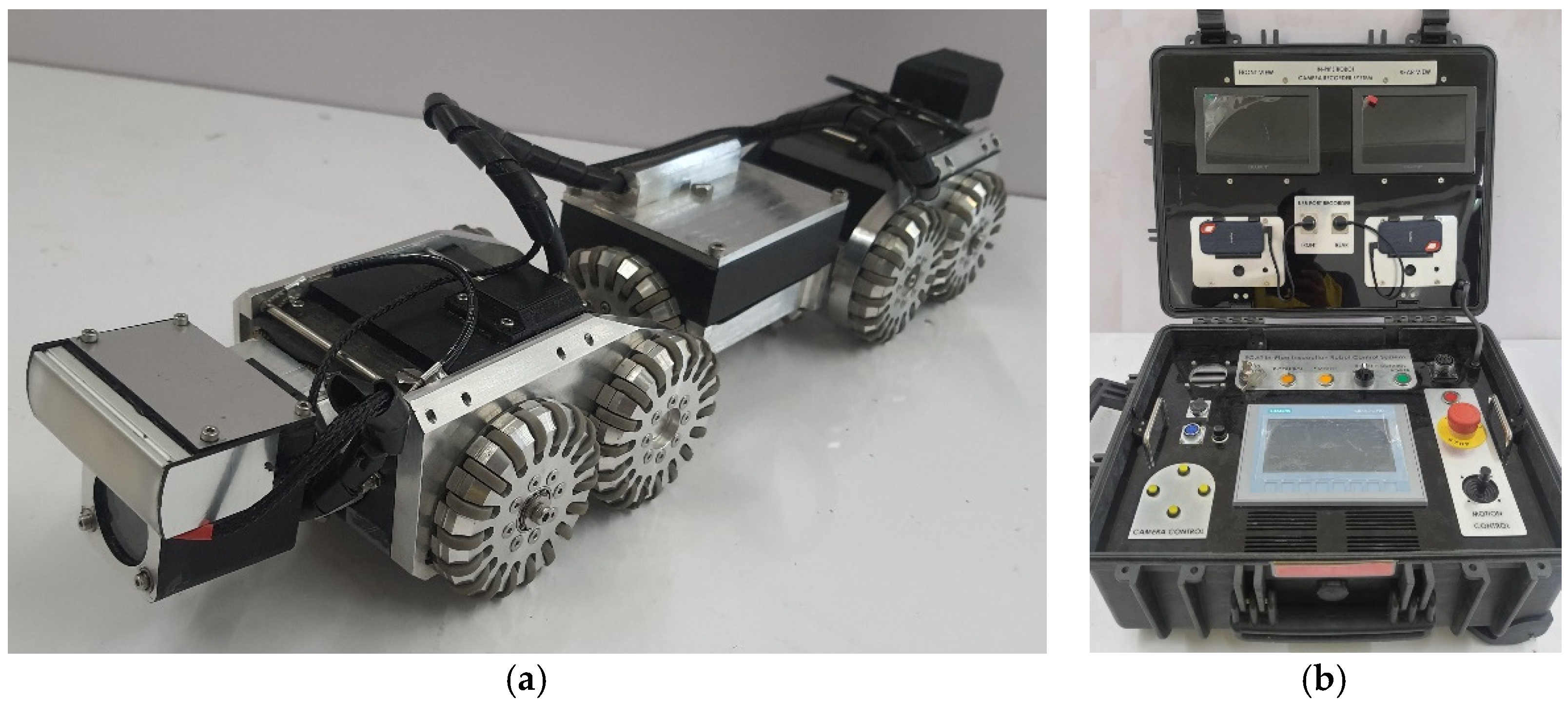
3. Prototype and Experiments

Figure 13 presents the prototype of the developed robot with the camera display panel and control panel. The robot is mainly composed of three modules with omnidirectional wheels. The wheels can be classified into six driving wheels and four supporting wheels. The front camera and headlamp are mounted on the front module. The rear camera and control cable are attached to the rear module. The parameters of the robot are summarized in Table 3. As shown in the table, several experiments were conducted to evaluate the performance of the prototype, e.g., the maximum velocity, payload capacity, and vertical distance that the robot is capable of climbing without slipping. The robot is also able to pass through a straight pipe in both horizontal and vertical directions.
To evaluate the robot’s capability to pass through a curved pipe, two experiments were conducted in an 8-inch (203 mm) diameter pipe, as shown in Figure 14a,b: a curved up elbow (horizontal to vertical) and a curved down elbow (vertical to horizontal). The results demonstrated that the robot can stably move in the upward and downward directions for both curved up and curved down conditions. However, irregular welds or uneven weld beads may occasionally cause the wheels to slip. Furthermore, the robot can move on the ceiling of the pipe, as shown in Figure 14c, in order to avoid any liquid or slag in the pipe. Figure 15 shows the real-world visual inspection from when the robot was used in a horizontal oil drainpipe at a real site.

4. Conclusions

In this article, a train-like inspection robot was proposed for the visual inspection of the inside of ferromagnetic pipes with a diameter of 5 inches (127 mm) or larger. The robot combined omnidirectional wheels and permanent magnets as the adhesion mechanism between the robot and the pipes. Two perpendicular sets of omnidirectional wheels provided two-directional movements (longitudinal and lateral) and ensured that the robot could travel longitudinally along the path of the pipe. The waterproof robot was designed for operation in waterlogged conditions. The visual control panels were used to control the robot’s movement and to observe the inspection area in real-time through the front and rear cameras. the robot was also equipped with temperature and humidity sensors to provide the real-time monitoring of the pipe’s internal conditions. The robot prototype was tested in several conditions in order to prove that the robot is capable of passing through straight and curved pipes in any direction. The developed robot can also be applied for the external inspection of ferromagnetic structures, such as ferrous storage tanks. Autonomous functionalities, such as surface examination and corrosion detection, are very interesting and will be the focus of our future investigation.

Author Contributions

Conceptualization, K.T.-O.; methodology, T.M. and A.B.; writing—original draft preparation, T.S. and K.K.; supervision, K.K.; investigation, K.T.-O., K.K., T.M., T.S. and A.B. All authors have read and agreed to the published version of the manuscript.

Funding

This research was funded by the Electric Generating Authority of Thailand (EGAT), grant number 60-F204000-11-IO.SS03F3008300.

Conflicts of Interest

The authors declare no conflict of interest.

References

  1. Kirchner, F.; Hertzberg, J. A Prototype Study of an Autonomous Robot Platform for Sewerage System Maintenance. Auton. Robot. 1997, 4, 319–331. [Google Scholar] [CrossRef]
  2. Xu, Z.-L.; Lu, S.; Yang, J.; Feng, Y.-H.; Shen, C.-T. A wheel-type in-pipe robot for grinding weld beads. Adv. Manuf. 2017, 5, 182–190. [Google Scholar] [CrossRef]
  3. Hadi, A.; Abdollahi, M.; Alipour, K.; Tarvirdizadeh, B. Design and Prototyping a New Add-on Module to Increase Traction Force of a Wheeled Sewer Inspection Robot. In Proceedings of the 2017 5th RSI International Conference on Robotics and Mechatronics (ICRoM), Tehran, Iran, 25–27 October 2017; pp. 254–259. [Google Scholar]
  4. Mohammed, M.N.; Nadarajah, V.S.; Lazim, N.F.M.; Zamani, N.S.; Al-Sanjary, O.I.; Ali, M.A.M.; Al-Youif, S. Design and Development of Pipeline Inspection Robot for Crack and Corrosion Detection. In Proceedings of the 2018 IEEE Conference on Systems, Process and Control (ICSPC), Malacca, Malaysia, 14–15 December 2018; pp. 29–32. [Google Scholar]
  5. Mills, G.H.; Jackson, A.E.; Richardson, R.C. Advances in the Inspection of Unpiggable Pipelines. Robotics 2017, 36. [Google Scholar] [CrossRef] [Green Version]
  6. Yaguchi, H.; Izumikawa, T. Wireless in-piping actuator capable of high-speed locomotion by a new motion principle. IEEE/ASME Trans. Mechatron. 2013, 18, 1367–1376. [Google Scholar] [CrossRef]
  7. Yang, J.; Xue, Y.; Shang, J.; Luo, Z. Research on a new bilateral self-locking mechanism for an inchworm micro in-pipe robot with large traction. Int. J. Adv. Robot. Syst. 2014, 11, 174. [Google Scholar] [CrossRef]
  8. Yum, Y.J.; Hwang, H.S.; Kelemen, M.; Maxim, V.; Frankovský, P. In-pipe micromachine locomotion via the inertial stepping principle. J. Mech. Sci. Technol. 2014, 28, 3237–3247. [Google Scholar] [CrossRef]
  9. Yim, S.; Jeon, D. Magnetic mechanical capsule robot for multiple locomotion mechanisms. Int. J. Control Autom. Syst. 2014, 12, 383–389. [Google Scholar] [CrossRef]
  10. Fang, D.; Shang, J.; Luo, Z.; Lv, P.; Wu, G. Development of a novel self-locking mechanism for continuous propulsion inchworm in-pipe robot. Adv. Mech. Eng. 2018, 10, 1687814017749402. [Google Scholar] [CrossRef] [Green Version]
  11. Suzumori, K.; Miyagawa, T.; Kimura, M.; Hasegawa, Y. Micro Inspection Robot for 1-in Pipes. IEEE/ASME Trans. Mechatron. 1999, 4, 286–292. [Google Scholar] [CrossRef]
  12. Roh, S.G.; Choi, H.R. Differential-drive in-pipe robot for moving inside urban gas pipelines. IEEE Trans. Robot. 2005, 21, 1–17. [Google Scholar] [CrossRef]
  13. Ciszewski, M.; Wacławski, M.; Buratowski, T.; Giergiel, M.; Kurc, K. Design, Modelling and Laboratory Testing of a Pipe Inspection Robot. Arch. Mech. Eng. 2015, 62, 395–407. [Google Scholar] [CrossRef] [Green Version]
  14. Kim, H.M.; Choi, Y.S.; Lee, Y.G.; Choi, H.R. Novel mechanism for in-pipe robot based on a multiaxial differential gear mechanism. IEEE/ASME Trans. Mechatron. 2017, 22, 227–235. [Google Scholar] [CrossRef]
  15. Zhang, Y.; Yan, G. In-pipe inspection robot with active pipe-diameter adaptability and automatic tractive force adjusting. Mech. Mach. Theory 2007, 42, 1618–1631. [Google Scholar] [CrossRef]
  16. Roh, S.G.; Kim, D.W.; Lee, J.S.; Moon, H.; Choi, H.R. In-pipe robot based on selective drive mechanism. Int. J. Control Autom. Syst. 2009, 7, 105–112. [Google Scholar] [CrossRef]
  17. Kuwada, A.; Tsujino, K.; Suzumori, K.; Kanda, T. Intelligent Actuators Realizing Snake-like Small Robot for Pipe Inspection. In Proceedings of the 2006 IEEE International Symposium on MicroNanoMechanical and Human Science, Nagoya, Japan, 5–8 November 2006; pp. 1–6. [Google Scholar]
  18. Fjerdingen, S.A.; Liljebäck, P.; Transeth, A.A. A snake-like robot for internal inspection of complex pipe structures (PIKo). In Proceedings of the 2009 IEEE/RSJ International Conference on Intelligent Robots and Systems, St. Louis, MA, USA, 10–15 October 2009; pp. 5665–5671. [Google Scholar]
  19. Schoeneich, P.; Rochat, F.; Nguyen, O.T.; Caprari, G.; Moser, R.; Bleuler, H.; Mondada, F. Tubulo—A train-like miniature inspection climbing robot for ferromagnetic tubes. In Proceedings of the 2010 1st International Conference on Applied Robotics for the Power Industry, Montreal, QC, Canada, 5–7 October 2010; pp. 1–5. [Google Scholar]
  20. Jeon, W.; Park, J.; Kim, I. Development of high mobility in-pipe inspection robot. In Proceedings of the System Integration (SII), 2011 IEEE/SICE International Symposium on, Kyoto, Japan, 20–22 December 2011; pp. 479–484. [Google Scholar]
  21. Takayama, T.; Takeshima, H.; Hori, T.; Omata, T. A Twisted Bundled Tube Locomotive Device Proposed for In-Pipe Mobile Robot. IEEE/ASME Trans. Mechatron. 2015, 20, 2915–2923. [Google Scholar] [CrossRef]
  22. Oka, Y.; Kakogawa, A.; Ma, S. Stopper Angle Design for a Multi-link Articulated Wheeled In-pipe Robot with Underactuated Twisting Joints. In Proceedings of the 2018 IEEE/RSJ International Conference on Intelligent Robots and Systems (IROS), Madrid, Spain, 1–5 October 2018; pp. 973–978. [Google Scholar]
  23. Tâche, F.; Pomerleau, F.; Fischer, W.; Caprari, G.; Mondada, F.; Moser, R.; Siegwart, R. MagneBike: Compact magnetic wheeled robot for power plant inspection. In Proceedings of the 2010 1st International Conference on Applied Robotics for the Power Industry, Montreal, QC, Canada, 5–7 October 2010; pp. 1–2. [Google Scholar] [CrossRef] [Green Version]
  24. Abdul Jalal, M.F.; Mohamed Sahari, K.S.; Anuar, A. Development of magnetic wheeled boiler tube inspection robot. J. Teknol. 2015, 76, 19–23. [Google Scholar] [CrossRef] [Green Version]
  25. Azlin, A.; Sahari, K.; Abdul Jalal, M.F.; Anuar, A. Development of 1-inch boiler tube inspection robot. In Proceedings of the 41st Annual Conference of the IEEE Industrial Electronics Society, Yokohama, Japan, 9–12 November 2015; pp. 004340–004344. [Google Scholar]
  26. Mills, G.H.; Liu, J.H.W.; Kaddouh, B.; Jackson, A.E.; Richardson, R.C. Miniature Magnetic Robots For In-Pipe Locomotion. In Proceedings of the 21st International Conference on Climbing and Walking Robots and the Support Technologies for Mobile Machines, Panama, Panama, 10–12 September 2018. [Google Scholar]
  27. Kawaguchi, Y.; Yoshida, I.; Kurumatani, T.; Kikuta, T.; Yamada, Y. Internal pipe inspection robot. In Proceedings of the 1995 IEEE International Conference on Robotics and Automation, Nagoya, Japan, 21–27 May 1995; Volume 1, pp. 857–862. [Google Scholar] [CrossRef]
  28. Boonyaprapasorn, A.; Thung-Od, K.; Silapunt, R.; Maneewarn, T. Studies of total adhesive force of multiple magnetic wheels for a climbing robot. In Proceedings of the 16th International Conference on Climbing and Walking Robots and the Support Technologies for Mobile Machines (CLAWAR), Sydney, Australia, 14–17 July 2013; pp. 578–584. [Google Scholar]
Figure 1. The 3D CAD model of the proposed in-pipe inspection robot.
Applsci 12 01226 g001
Figure 2. The side view of the robot configuration with the passive linkage mechanisms.
Applsci 12 01226 g002
Figure 3. The 3D CAD design of the omnidirectional wheel.
Applsci 12 01226 g003
Figure 4. (a) The size of the robot relative to the pipes of different sizes. (b) The shim plate installation.
Applsci 12 01226 g004
Figure 5. The parameters for the shim plate thickness calculation.
Applsci 12 01226 g005
Figure 6. The 2D simulation results of the magnetic flux distribution: (a) The magnet in the ferromagnetic pipe; (b) the magnet on the ferromagnetic flat plate.
Applsci 12 01226 g006aApplsci 12 01226 g006b
Figure 7. The free body diagram and static force analysis of the in-pipe inspection robot.
Applsci 12 01226 g007
Figure 8. (a) The experimental setup and (b) the results demonstrating the influence of distance on the magnetic force.
Applsci 12 01226 g008
Figure 9. A kinematic model of the in-pipe robot with (a) perspective view and (b) side view.
Applsci 12 01226 g009
Figure 10. The schematics of the robot’s electrical diagram.
Applsci 12 01226 g010
Figure 11. A diagram of the camera display panel.
Applsci 12 01226 g011
Figure 12. A diagram of the robot’s control panel.
Applsci 12 01226 g012
Figure 13. (a) The prototype of the developed in-pipe inspection robot; (b) the camera display panel and the robot’s control panel.
Applsci 12 01226 g013
Figure 14. The experimental setup to evaluate the robot’s capability to pass (a) through a curved up elbow, (b) through a curved down elbow, and (c) by attaching to the ceiling.
Applsci 12 01226 g014
Figure 15. The internal surface of the pipe captured by the front camera: (a) a rusty surface; (b) slag ash.
Applsci 12 01226 g015
Table 1. The suitable thickness of the shim plate for various pipe sizes.
Pipe Diameter (in)567891011Flat Plate
Shim Plate Thickness (mm)181412109871
Table 2. The power, speed, and torque requirements of the motor.
Power (W)Speed (rpm)Torque (Nm)
Calculated results of motor requirements3137,8360.0078
Maxon’s EC16 motor with GP16A gearhead specifications3038,1000.0083
Table 3. The specifications of the prototype of the developed robot.
ParametersValue
MaterialAluminum, nylon, and PLA
Dimension110 mm × 99 mm × 450 mm
Weight3 kg
MagnetNeodymium block 40 × 20 × 10 mm N35
Wheel diameter10 cm
Power220 V 50 Hz
Top speed30 cm/s
Working spaceIn-steel pipe, from 5-inch (127 mm) diameter to flat plate
Payload59 N
Vertical distance10 m
Control cable length50 m
MotorMaxon EC16 30-watt brushless DC motor
Motor gearGP16A ratio 104:1
Robot gearSpur gear ratio 4:1
Analog cameraFOV 160° 1000TVL
Camera display7 inches
Sensors3 humidity sensors and 4 temperature sensors
Publisher’s Note: MDPI stays neutral with regard to jurisdictional claims in published maps and institutional affiliations.

