
On BIM Interoperability via the IFC Standard: An Assessment from the Structural Engineering and Design Viewpoint


1
Department of Engineering, University of Campania “Luigi Vanvitelli”, 81031 Aversa, Italy
2
StreGa Lab, Department of Biosciences and Territory, University of Molise, 86100 Campobasso, Italy
3
Napoli Branch, National Research Council, ITC-CNR, Construction Technologies Institute, 80146 Napoli, Italy
4
L’Aquila Branch, National Research Council, ITC-CNR, Construction Technologies Institute, 67100 L’Aquila, Italy
*
Author to whom correspondence should be addressed.
Appl. Sci. 2021, 11(23), 11430; https://doi.org/10.3390/app112311430
Submission received: 20 October 2021
/
Revised: 19 November 2021
/
Accepted: 22 November 2021
/
Published: 2 December 2021
(This article belongs to the Special Issue Synergy of Building Information Modeling and Optimization in Civil Engineering)
Abstract
:Building information modelling (BIM) plays a prominent role in a good deal of architecture, engineering and construction (AEC) works, envisaging a full transition to digitalization for the construction industry. This is also due to a number of national and international regulations regarding the design, erection, and management of civil engineering constructions. For this reason, full interoperability of software environments such as computer-aided design (CAD) and computer-aided engineering (CAE) is a necessary requirement, particularly when the exchange of information comes from different disciplines. Users, throughout the years, have faced CAD–CAE interoperability issues despite following the IFC neutral open file format. This inability to share data (CAD to CAD, CAD to CAE) often generates model-interpretation problems as well as a lack of parametric information and a disconnection of elements. This paper addresses issues and mapping mechanisms in the exchange of data for the purpose of defining a baseline for the current status of bidirectional data exchange between AEC CAD/CAE software via the IFC format. A benchmark study, covering three years of software releases is illustrated; the assessment of the software performance was made with reference to criteria associated with the software’s level of suitability for use of the structural models. Four classes of performance, depending on the accuracy of the data transfer and on the associated corrective actions to be taken, were adopted. This confirmed that at the moment, the implementation of the IFC standard by software manufacturers is geared towards an expert class of users. Further efforts are needed in order to ensure its application is adopted by a wider class, thus extending and regulating its use by national, regional, and local authorities.
1. Introduction
The AEC (architecture, engineering and construction) industry is experiencing a revolution due to the fast development of the building information modelling (BIM) sector. BIM represents a new paradigm of the construction process and asks for novel answers to the problems of data sharing and intellectual property rights definitions [1]. It is a complex platform aimed at preserving all relevant information related to any phase of the construction lifecycle and needs several, heterogeneous data-exchange capabilities.
As a result, the interoperability (i.e., the ability to exchange any kind of data between applications), which smoothens the workflow and often facilitates automation, is the key feature of the process [2].
The demand for interoperability between different software packages has experienced increased growth in the AEC market [3], especially in Europe, where regulatory bodies have issued new rules for the digitalisation of the civil engineering sector [4,5,6].
The mandatory use of the BIM platform on a large scale has expanded the need for easy and reliable information-exchange processes that are able to preserve data and their quality and has increased the importance of a substantial integration of the various disciplines related to the AEC world [7,8,9]. Full interoperability is what is expected in any design context where several software packages are adopted by users and a set of local or national authorities are required to interact with all the players in the process.
As far as the design of new structures is concerned, architects and engineers closely collaborate on a construction project. Architectural design is commonly performed in a modelling environment termed computer-aided design (CAD), whereas engineering design takes place in a simulation and analysis environment called computer-aided engineering (CAE). Therefore, the transition from CAD to CAE is one of the basic phases of the BIM process. A common trend in the design process is towards a fully integrated design environment that combines geometric modelling tasks with computer simulation tasks, until the final design is delivered.
Given effective and reliable software interoperability, it is theoretically possible to directly switch from a CAD model to a CAE one. This is possible if all the software tools can share information taken or extracted by the same digital legacy model.
It is worth noting that interoperability is a complex concept and cannot be uniquely defined. A first general distinction is made based on the path of the user workflow [10]. Horizontal interoperability is defined as a data exchange between two architectural BIM software environments, such as the CAD-to-CAD path. Vertical interoperability, on the other hand, refers to a data exchange between architectural and structural software environments, such as the CAD-to-CAE path [9]. What is required more and more is the need to work in a bilateral environment in which the data exchange occurs bilaterally from/to any computer-aided (CAx) environment (i.e., CAD-to-CAE-to-CAD).
As reported in [11], two main types of data transfer paths between two design environments exist depending on the way the information is exchanged:
- Direct link (DL) uses an automatic connection between two different software environments by a plug-in expressly released for that purpose. Data from the sending environment are mapped onto the data from the receiving environment; thus, no external intermediate data translator is needed, and the exchange process appears to be highly efficient, even though it depends upon proprietary formats.
- Neutral link (NL) consists of adopting an independent exchange format; it is the most appropriate approach to a BIM-oriented methodology and represents a key step for the BIM environment. Most data that describe buildings, related to the building disciplines and to the several phases of the building lifecycle, are collected and managed by a neutral format. The main objective of neutral formats is to ensure long-term access to data without uncertainty regarding legal rights or technical specifications.
The most frequently used open neutral format in BIM is the Industry Foundation Classes (IFC), developed by buildingSMART. It is the de facto standard format that describes objects, their characteristics, and their relationships. It defines the standard for the technical exchange of files with model data and it is certified (ISO 16739-1:2018). IFC can be labelled the core of a collaborative-lifecycle BIM and aims to ensure the interoperability of BIM software, independently from the CAD/CAE software [12].
The most relevant advantages of an IFC-based BIM approach are its ability to: (i) combine the functionalities of different software applications, (ii) compare results between different analysis runs, and (iii) share project materials across different disciplines and phases [10]. IFC-based horizontal interoperability is widespread and, in principle, a BIM-based CAD software can adequately manage the exchanged information of an architectural model. In reality, several issues arise from the BIM interoperability, involving the exchange between CAD/CAE software. In the transition from a geometrical/architectural model to an analytical/structural model for structural analysis, vertical interoperability shows all its shortcomings, highlighting how, despite the fact that the IFC format can deal with structural information, the software’s implementation of all its functionalities is still limited. A recent critical review related to BIM CAD-to-CAE interoperability was reported by Sibenik and Kovacic [13], showing that criticalities in the connection between structural elements exist independently from the tested software.
In the present study, the level of interoperability reached by several very common commercial CAD and CAE BIM-based software implementing the IFC format was investigated. The assessment was designed to provide to the technical community and to the authorities in charge of the management of complex civil engineering works a qualitative and quantitative analysis of the issues in data exchange processes using NL procedures.
Attention was paid to the way in which the software packages dealt with the geometries and additional information exported and imported in the CAD–CAD and CAD–CAE bidirectional paths, adopting both the most common (IFC 2x3) and the latest (IFC 4) formats. We also focused on CAD–CAE bidirectional interoperability, which is a key aspect of BIM interoperability. The shared building information model was expected to be re-editable by the receiving application, and the end user should have been able to access any information within the model and edit it when and where needed.
Moreover, the results of self-tests (from CAD and CAE to IFC, then back to the same CAD and CAE) [14] are reported to offer a better understanding of the way a software environment can handle the IFC entities. Useful and significant outcomes that delve deeper into the translation and mapping mechanisms implemented into the software are also proposed.
The present study covers a three-year period during which the authors tested different releases of the same software packages, and so the elements that changed over the years are also reported. The assessment was intended as a reference and a guide to the most common dissimilarities in the data treatment that can cause issues or prevent the data exchange from being successful; obviously, it was not designed to rank software packages and their performance in the AEC process.
The paper is divided into eight sections. Section 2 shows some important aspects of the IFC standard related to versions 2x3 and 4 and provides schemas to describe the data exchange for a specific use or workflow. It also addresses the choice made in the benchmark study. Section 3 reports several useful contributions to data interoperability via IFC released in the past ten years. Section 4 analyses the CAD and CAE software solutions selected for the benchmark study and explains the methodology and the criteria adopted to test the horizontal and vertical interoperability. A detailed workflow was made for several software and a comparative study was carried out. Section 5 reports the results of the investigation and comparative tables are shown for all the explored source software and IFC formats. The mapping results from iterative self-tests are also reported. Several critical issues related to the disconnected joints of elements that were subjected to experimentation in the CAE for structural-analysis translation are also pointed out in Section 6. Section 7 discusses the results of the investigation. The last section draws some concluding remarks.
2. Industry Foundation Classes, a Brief Overview
IFC is an open format of data exchange that is well established worldwide in the field of BIM. The IFC file format (“.ifc”) enables the exchange of data not only associated with the geometrical properties of the components, such as walls, beams, and columns, but also heterogenous attributes, i.e., the mechanical and physical properties, costs, construction work time, and much more. The IFC format is designed for making an object-oriented data model of a civil engineering construction truly interoperable between different software packages. The IFC architecture is based on the structure of the STEP standard [15] and has been continuously developed by buildingSMART since the first data model standard release, IFC 1.0, dating back to 1996.
Over the years, every new proposed release—the current version is labelled as IFC 4.1—introduced new concepts to the IFC specification to catch more exchange-use cases and to improve existing definitions based on the lessons learnt from the implementation and usage [16]. The assessment of the IFC 2x release, published in 2000, confirms the described approach. More recently, IFC 2x3 [17], released in 2006, has been widely promoted by all software houses, often supported by the certification of conformity from buildingSMART [18].
IFC 4 is the most recent release, issued in 2013 (ISO 16739:2013) and updated to IFC 4 ADD2 TC1 (ISO 16739-1:2018). The latest version, IFC 4.1 (2018), is recommended by buildingSMART for all current developments. A very recent, but still under development, release is IFC 4.3, which extends the IFC schema to the domains of railways, roads, ports, and waterways [19]. The improvements to IFC 4 are related to a new documentation format, extensions of IFC in structural areas, and enhancements of geometry description [19]. Generally speaking, the IFC 4 format overcomes the limits of the past formats in data-exchange between different platforms [20].
The higher the complexity of the work to be accomplished, the greater the diversification of the professional skills involved in the process, and consequently, the greater the quantity of information to be exchanged. Often, most of this information is redundant or even useless for specific phases of the design or, in general, for the building project workflow [21]. This results in a lack of efficiency in the work phases and difficulty managing the types of exchanged information. However, this exchange must be supported by the different software packages involved in the process during the lifecycle of a structure; therefore, the correct interpretation of the exchanged information takes a fundamental role. This concept is at the base of the model view definition (MVD), a subset of the IFC scheme, which permits the exchange of information in different areas of the design and construction process of a building and defines the dataset to be transferred depending on the particular use.
Each IFC version is associated with a series of official buildingSMART MVDs. The most common model view is the Coordination View 2.0 [22], related to IFC 2x3, which can deal with both architectural information and structural analysis data. The CV 2.0 is a wide schema, covering the data related to both the CAD and CAE processes. The structural analysis view schema, also labelled the Structural Analysis View (SAV) [23], is an MVD belonging to IFC 2x3 TC1 [24]. The purpose of the SAV is to integrate information related to structural engineering, such as loads and load conditions, boundary conditions, constraints, materials, and connections between the elements.
The standard format IFC 2x3 implements the structural analysis schema, with all the basic information to effectively operate without relevant data dispersion, except for the data related to the dynamics of the structures not yet implemented in that standard.
IFC 4 extended the support for geometries and parametric data, building services and structural domains, and GIS mapping. It is currently not yet supported by all software packages and has implemented by two new MVDs. The Reference View (RV) has the purpose of defining a substantially non-modifiable reference model. In this case, the data exchange is unidirectional, and its use is mainly linked to the validation and verification of the project, such as code checking and clash detection, and, in general, applied to the resolution of issues resulting from geometry. On the other hand, the Design Transfer View (DTV) answers the need for the transferral of data that is to be used in different contexts, such as design, analysis, cost estimating, and facility management [25]. It allows the modification of the model by the receiver system and facilitates the exchange of information including MEP (mechanical, electrical, and plumbing), structural analysis environment, and building service (management). The DTV can be understood as a CV 2.0 with an extended range, while the IFC 4 RV schema is like the CV 2.0 but with slightly limited possibilities for changes to be made by the receiving environments. IFC translators can be implemented according to the standard practice, and then checked by buildingSMART before the official certification is released.
The certification of IFC 4 by buildingSMART started in 2017 (for the RV) and is ongoing for the DTV, as much of the certification job is still concentrated on IFC 2x3 CV 2.0 [18]. This element is important for the results of the current data-exchange study.
BuildingSMART provides an ongoing platform and process to certify applications that successfully pass the conformance testing, which mainly consists of comparing a product to a reference system. Lipman et al. [26] investigated several methods and rules for defining the structure, granularity, and verdict criteria of a test suite for construction product data-exchange standards. They reported that more accurate and specific tools are needed for checking the syntax and structure of test files, and for assessing semantics.
3. IFC Interoperability, a Literature Review
Table 1 collects the main studies available in the technical literature on IFC-based interoperability involving structural analysis and design problems, produced within the past ten years. It also depicts the contribution of the present study in this context and its novel aspects, such as the assessment of IFC 4 DTV, which has rarely been documented before. As previously stated, (see Section 2), this study used the model view definition SAV in different software environments to focus on the interoperability process specifically dedicated to structural analysis.
Early studies dating back to 2008, carried out by Pazlar and Turk [27], on the horizontal interoperability of the most common IFC-compatible software, focused on the IFC 2x Add1 format and the Extended Geometric View MVD, showed that the IFC interface did not work as expected. Many cases of distortion or loss of information related to the geometry of the elements, such as the non-alignment of beams, columns, and walls, resulting in an incorrect connection between the elements, were observed. Other typical problems were related to the loss of attributes and properties, such as the change of materials, colours, and the artefact shape of the elements.
Despite the evolution of the IFC format, switched from IFC 2x Add1 to IF C2x3, and the introduction of the additional MVD, namely, the Coordination View v2.0, the loss of data continued to exist, and other case studies showed that the problem related to the incorrect interpretation of the geometry of the elements and results was still widespread.
One of the first trial studies was carried out by Jeong et al. [28] and focused on detailed benchmark tests using a small but complex building model that implemented IFC 2x3. Imperfect exchanges were observed due primarily to the lack of uniformity in the way the internal object schemas were mapped onto the IFC objects and properties. Reference BIM packages included Revit, ArchiCAD, Digital Project, Bentley Architecture, and Tekla Structures.
A data exchange analysis between two of the most popular BIM software, Revit and Tekla, was presented by Nizam and Zhang [29]. Models were exchanged by using IFC CV 2.0, and a comparison was made in terms of data loss and misrepresentation of geometry and section types. The loss of data related to geometry, profile, and material was also reported by Chiaia et al. [9], who tested horizontal and vertical interoperability between CAD software, such as Revit and ArchiCAD, and CAE software, such as AxisVM, in a bidirectional data exchange using IFC.
Sibenik [30] documented a study carried out in three different BIM authoring tools, i.e., AllPlan, Revit, and ArchiCAD; the geometry representation of the building in the structural analysis software was evaluated in terms of consistency and usability via two CAE software: RFEM and SCIA Engineer. Inconsistencies, such as data transfer losses or misinterpretations of linear elements, planar elements, and connectivity, were reported.
Taher [31] evidenced the lack of proper communication between BIM software and the open format IFC containing some practical deficiencies. The work was carried out to test the use of BIM in structural design and calculations using several commercial BIM software and structural BIM tools (S-BIM Tools) such as Revit, Robot Structural analysis, Rhinoceros, and Tekla structures.
The application of interpreted information exchange (IIE) for engineering analyses was illustrated by Ramaji and Memari [32]. An explanatory platform was created to implement the structural analytical model, starting from the architectural model; the authors observed that despite the MVD standard (CV 2.0) being widely adopted by BIM-based software, most design/analysis software packages were not able to export structural MVDs. As a result, the geometry of the elements was subjected to changes, while other information such as the loads and the responses of the structure were not transferable. These comments were applied to SAP2000, Tekla Structures, and SCIA Engineering, the packages used as a reference.
Muller et al. [33] paid attention to the interoperability assessment of the BIM system in the structural domain, considering in particular cast-in-place concrete structures. Experiments with structural elements imported and exported through the IFC format were conducted twice, with a five-year gap between them. The results showed that in this period, an evolution of the performance in terms of interoperability occurred, but most of the major problems, such as the overlapping of structural parts, still persisted; such results applied particularly to Revit and TQS packages.
A bidirectional-interoperability data exchange using IFC was conducted by Lai and Teng [34], which included architectural, structural, and MEP models to analyse issues in the process of data import and re-export between heterogeneous software such as ArchiCAD, Tekla Structures, and MagiCAD for Revit. The authors pointed out the different interpretations of objects from domains.
The interoperability between architectural design and structural analysis was also investigated by Aldegeily et al. [12]. Their objective consisted of exploring BIM-based structural analysis through data transfer between different software, such as Revit, Robot Structural Analysis, SAP2000, and ETABS, via a direct link using a native file or API interface and a neutral link such as IFC. The authors found that IFC was unable to ensure a comprehensive transfer of the relevant data, such as the loads.
Marcolin [35] investigated the implementation of IFC schemas for the dynamic analysis of structures using structural-specific MVDs for both IFC 2x3 and IFC 4 and documented the loss of information in the CAD/CAE data exchange.
Sibenik and Kovacic [13] provided a comprehensive interoperability assessment report testing IFC 2x3 for both architectural design and structural analysis involving CAD systems such as ArchiCAD, Revit, and AllPlan, and CAE systems such as RFEM and SCIA. After highlighting the issues already mentioned in the study previously recalled [30], they directed attention to the need to (i) focus the data exchange on multiple domain-specific building data schemas instead of on the integrated schema, and (ii) develop a new certification process based on the domain-specific building data schema.
The above studies showed the issues related to the CAE environment as a receiving platform. In these cases, the interoperability of MVDs closely related to the structural design environment were tested, such as the SAV for the IFC 2x3 format.
However, none of the studies reported in the relevant technical literature paid attention to the IFC 4 interoperability workflow, even though it is a standard dating back to 2013 and updated in 2018. Nevertheless, many software vendors claim the ability to also interoperate with the IFC 4 format.
4. Test Methodology and Evaluation Criteria of Data Interoperability
One of the main novel aspects of this study was its attempt to fill this gap and to provide an overview of the current interoperability achieved via IFC among several commercial BIM-based CAx software, with specific attention paid to the structural analysis aspects in CAE environments of structures made of monodimensional members.
This objective was pursued by analysing how geometric and non-geometric data were exchanged and the mechanisms that were involved in the failure of the data-exchange process. The specific perspective of the structural engineer was adopted, since the structural analysis and design of each construction is a diverse and key phase of every architectural project; therefore, an attempt was made to provide a picture of the interoperability involving structural data transfer.
Furthermore, a cross-exchange between CAD systems was also performed, so that the up-to-date current status of the interoperability at the CAD level could be determined.
Three levels of interoperability were selected: (i) CAD-to-CAD; (ii) CAD-to-CAE; (iii) CAE-to-CAE.
An analytical and realistic approach based on the comparison of software capability and the key factors that differentiate software performances was adopted. The IFC object-mapping mechanism within some software packages was also a point of focus for repetitive self-tests.
A selection of the most common BIM-based CAD and CAE software available on the market was made and is reported in Table 2.
The assessment started at the end of 2017 and was updated until the most recent software releases (at the time of writing), so the evolution over time of the software performance was also reported. Version (A) and (B) in the tables indicate the starting releases and the final releases of the tested software packages, respectively (simply recalled as A and B in the following tables for sake of brevity).
Table 3 and Table 4 summarise the versions of the IFC formats supported by all software environments tested in the present work, for import and export, respectively. The tables show that some companies over the years extended their software’s ability to work with IFC, including IFC 4, and their ability to handle structural analysis elements (labelled as Structural Analysis View in the tables) in both the IFC 2x3 and IFC 4 formats.
In an ideal BIM-interoperability workflow, the end user should be able to work in any CAD system and transfer the model to any CAE system to run simulations; if changes are applied to the analytical model, it is expected that the model will be returned to the CAD level to update the corresponding architectural model. CAD-to-CAD and CAD-to-CAE data exchange can also occur in a large design context involving different computer-aided solutions.
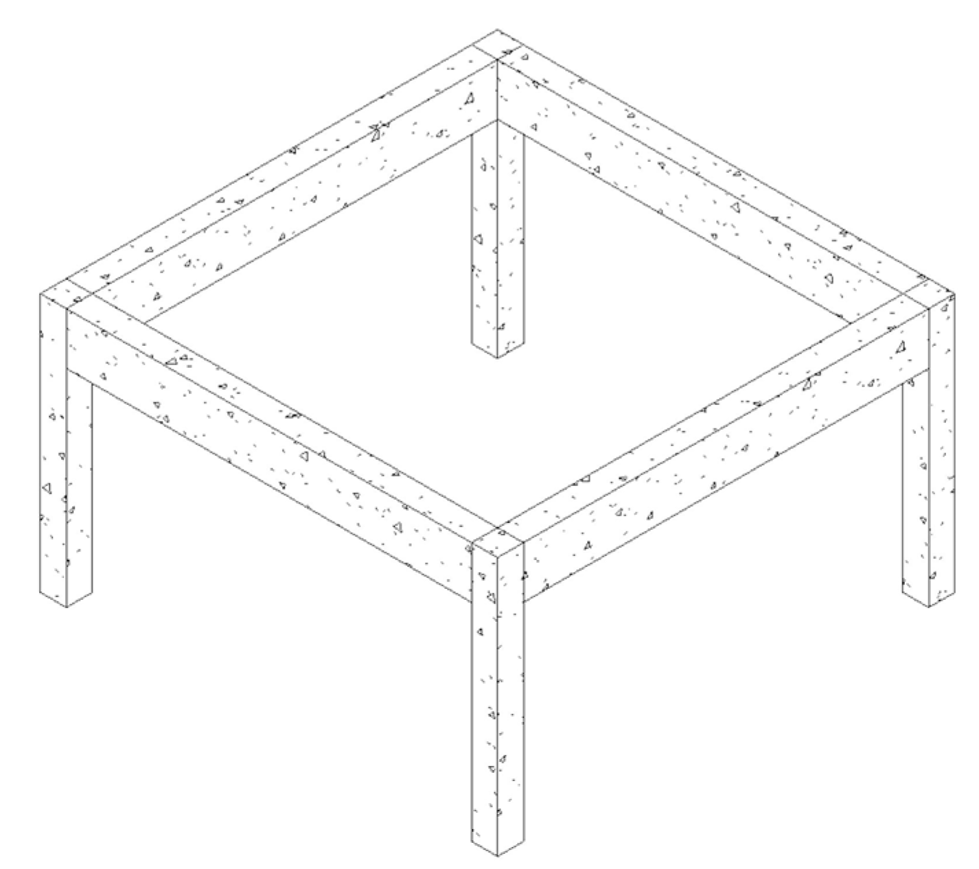
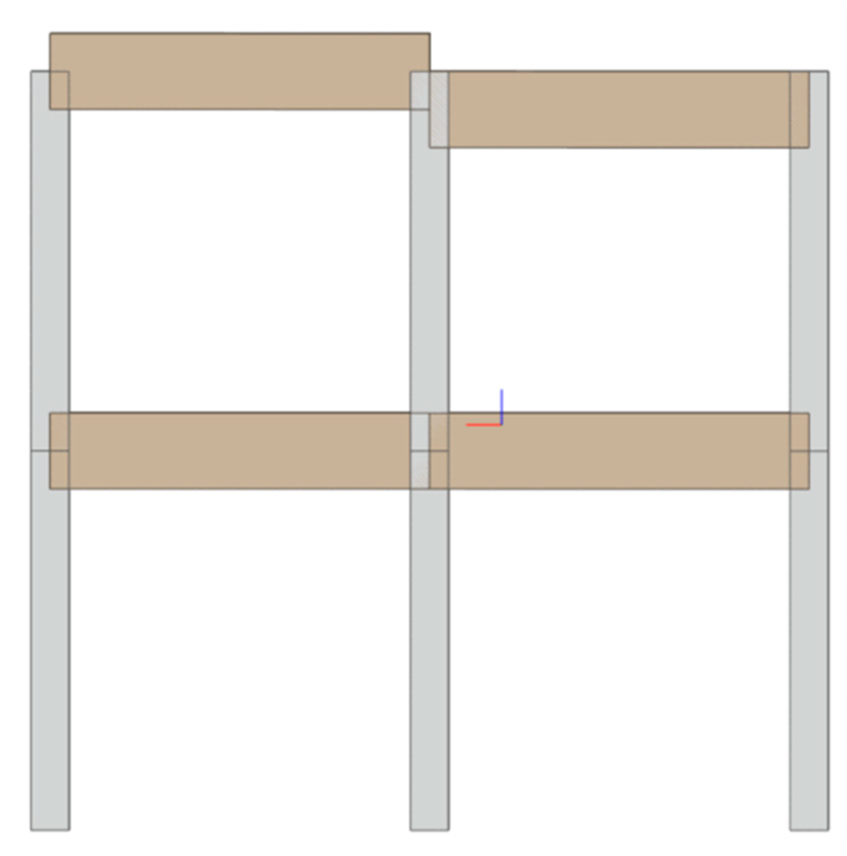
After conducting some preliminary tests on both simple and quite complex architectural models, different behaviour and a wide range of differences in the data exchange process were observed, particularly in the case of monodimensional members, such as beams and columns, whose utilization was independent upon the construction material. This circumstance led us to carry out complete interoperability tests on a very simple structural model, such as the 3D frame shown in Figure 1. It consisted of 4 columns and 4 beams and was designed in each CAD system using the same modelling approach; a preliminary model check was made by using internal tools, wherever available. In fact, an element to be considered was that, more often than expected, the lack of proven modelling guidelines and best practices was at the root of the interoperability problems. For quite complex projects, many different methods could be adopted to create, for example, a solid model using several combinations of union, intersection, addition, and subtraction features, but standard rules specifying the preferred modelling practices are important and design companies should train CAD users in the preferred methods for modelling parts and assemblies [46]. This refers specifically to mechanical CAD systems, but it can be applied to the AEC context, too.
The main features of the 3D frame are listed below (dimensions in mm):
- Reinforced concrete columns, section size 300 × 300, height 3000;
- Reinforced concrete beam, section size 300 × 600;
- Material: reinforced concrete C28/35, according to Eurocode 2 (CEN, 2004).
Before exporting the CAD model, a preliminary analysis was carried out to find the best conversion parameter settings to achieve an acceptable transfer by using IFC viewer tools, particularly BIMvision [47]. All the suggested settings for each environment that were available in the software help guides, and those recommended by international organizations, were adopted. The selection of the most appropriate options before translating the data via IFC was essential for the correct interchange of the model, both when importing and especially when exporting data. Most software offered the possibility to edit several parameters that could affect the resulting model. Each program had a different set of options, and during the benchmark the same options, if any, have been maintained.
Four evaluation criteria were defined based on the interoperability studies available in the literature and reported in a matrix summarising the results. The geometric correspondence between the original model and the imported model was evaluated, determining the degree of fitting, possible distortions, missing elements, and position changing. The correspondence of the materials used was verified according to properties such as Young’s modulus, density, and similar things. Other parameters were analysed, including the capability of reading and changing the most important characteristics of the elements such as dimensions, location between the points, dimensions, section type, size, and shapes. For each of the aspects considered, a summary table was arranged to report the results based on a five-level score-evaluation system:
- Poor. Strong lack of correspondence between the exchanged information; data and/or geometry missing or hard to reconstruct in the receiving system; model affected by severe flaws that prevent its utilization.
- Fair. Several losses of information needed for the immediate correct use of the model; the user needs to remodel and/or reassign key parameters.
- Average. Most of the information is preserved; the model can be used after just a few changes; not much additional information provided.
- Good. The correspondence of information is good, and after minor adjustments, the model is ready for analysis.
- Excellent. Perfect matching of all information.
In the next section, for each system involved, more details about the inaccurate data exchange are provided to justify the assigned score.
5. Summary of the Interoperability Tests
The benchmark model was analysed using different IFC formats and MVDs. For each IFC MVD format, a summary table reports a symbolic score associated with the abovementioned evaluation system (refer to Table 5, Table 6, Table 7, Table 8 and Table 9). The results were reported with respect to both the software releases tested in this study, named A and B for the first and last releases, respectively. If significant changes were found between the results, they were reported in the comments for each sending software. All the exported models were checked with the BIMvision viewer, mainly for the geometrical aspects, and they all corresponded to the original native models. Section 5.4 focuses on the reports of the self-tests that point out the internal-mapping procedures adopted by the software.
5.1. Use of IFC 2x3 Coordination View 2.0 (CV 2.0)
The first export/import test, which aimed to verify both the horizontal and vertical interoperability, was carried out on the most popular IFC format, IFC 2x3 CV 2.0. The outputs of the tests are described below for each sending software:
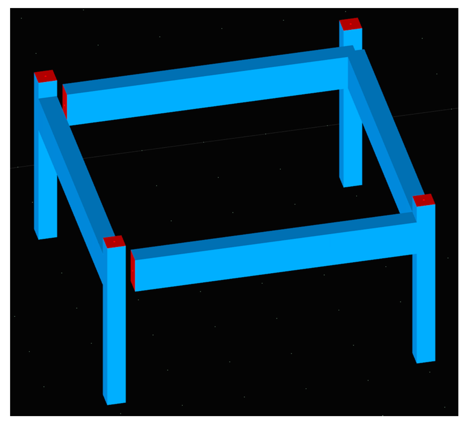
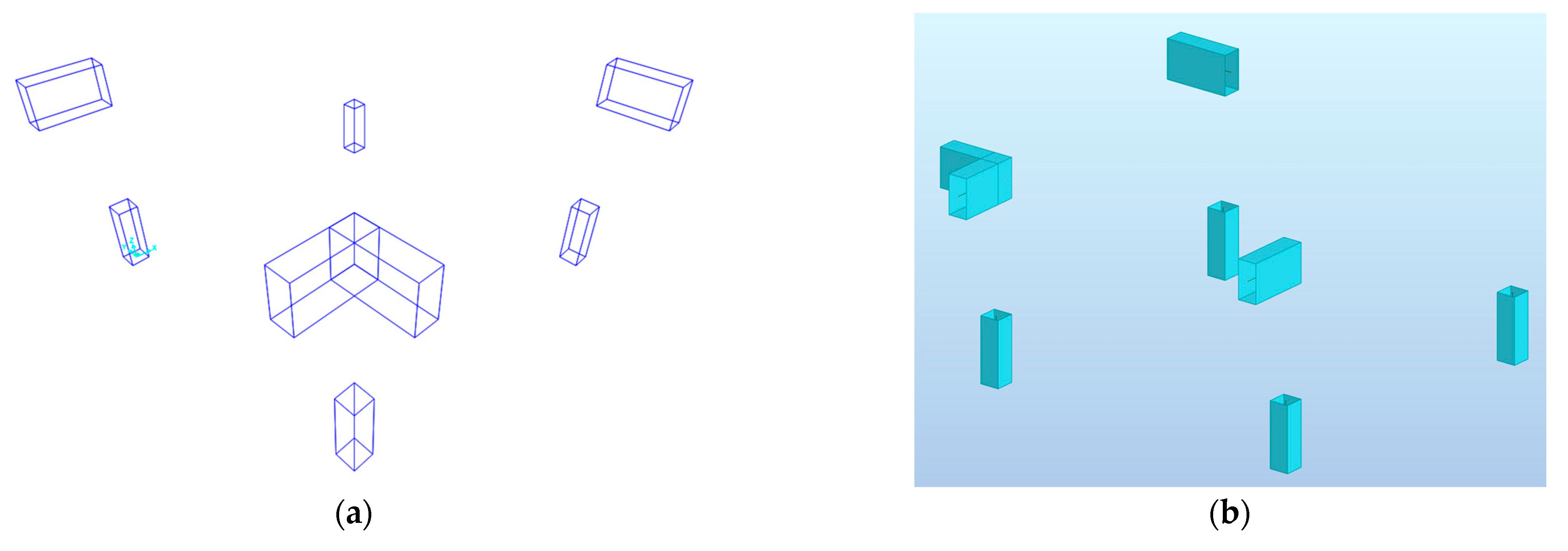
- Autodesk Revit. The CAD model generated in Revit was exported as an IFC file and imported into other environments. Due to the number of different settings (i.e., additional export content, level of details, and advanced settings) requested by the export interface, this task was not trivial; some knowledge about the way the receiving systems could handle IFC entities may have improved the exchange process, according to the software guide. Concerning the horizontal interoperability, the imported geometrical model agreed with the original model, while the material data was limited to only the material name. In terms of the parameters, some differences were found. The self-test showed that the section dimensions were not fully editable (i.e., only the length could be changed but not the section size). Even some dimensions, such as the relative location of columns, could not be directly edited. On the other hand, the model imported in Allplan and ArchiCAD was fully interoperable. In Edificius, the IFC file had to be imported into a new project, but it allowed us to edit very few simple features, such as colour, transparency, snap, and so on; the imported file was essentially a reference model. Among the CAE environments, geometry issues occurred in RSA and SAP2000: beams appeared 90° rotated around their axes (Figure 2a). The analytical model generated in RSA from the geometrical model showed disjointed elements, requiring additional editing in the receiving software (Figure 2b). As far as RFEM was concerned, the software was unable to import the four columns due to their different representation type adopted by Revit; more details about this aspect are provided in the discussion section later. The material data could be associated with the objects only if their imported name matched the internal material library. ModeSt, on the other hand, could correctly read the model in terms of geometry and material information content, while some parametric features were lost (the parametric locations of the elements). Similarly to ModeSt, Tekla Structures worked well, and with the use of the convert IFC object command, the user could easily modify all the geometric parameters. Steel material was associated with all the components originally defined as reinforced concrete. Edilus could correctly import the model, but no parametric changes were allowed.
- ArchiCAD. Thanks to the possibility to choose pre-configured IFC settings for different input/output software, the end user could customise the export file in ArchiCAD based on the destination environment. For the horizontal interoperability, there were no significant differences compared with the previous case (from Revit); thus, the same scores were applied.However, the self-test worked better than before, as the software also recognised the assigned materials of the objects (in other cases, only the material name was provided). With IFC 4, a new material (with customised mechanical properties) was also fully recognised. Concerning the vertical interoperability response, the export template for structural analysis was able to convert the geometry in only the structural elements, thus avoiding including unnecessary geometrical data and other elements such as furniture, finishes, etc.The global behaviour was better than the Revit result. RFEM could correctly read the IFC model in terms of geometry and materials. The section type and materials parameters could be edited very quickly and in detail. However, the object sizes were not editable in as straightforward a manner as for the native objects. SAP2000 interpreted the beams as elements rotated 90° with respect to the original objects. For EdiLus, the same considerations as for Revit applied.
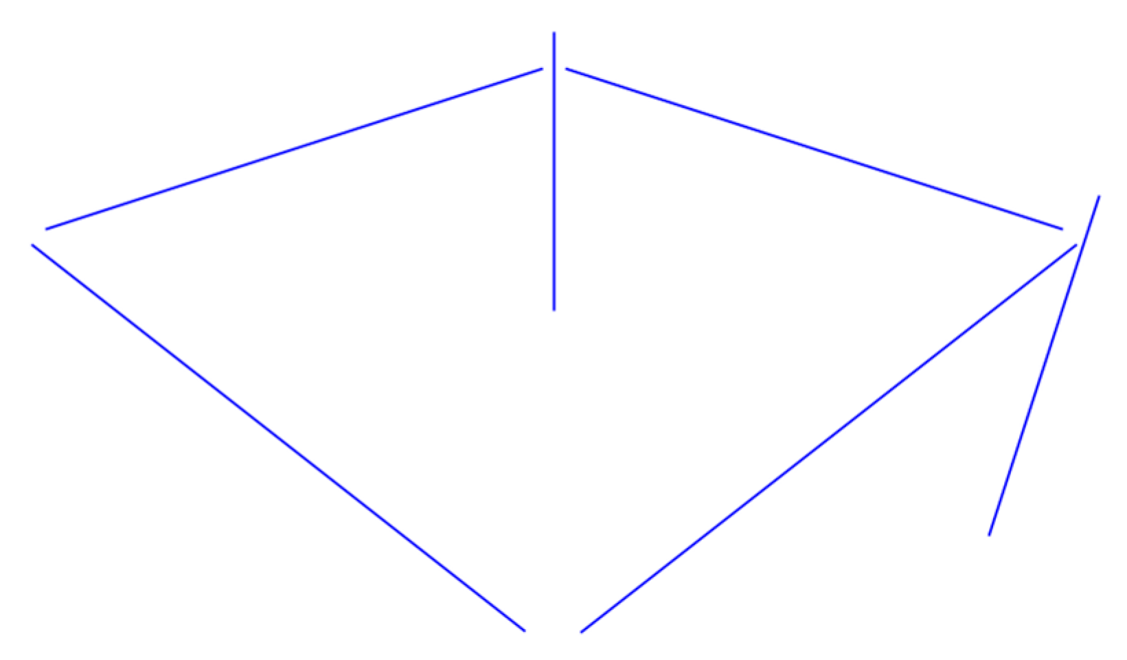
- Allplan. Allplan worked similarly to ArchiCAD for the horizontal interoperability test. The material information was limited to the name only, or the general material was assigned. When exchanging data with the CAE software, more missing data occurred. In RSA and SAP2000, some columns disappeared (with IFC 4 RSA, only one column was read), and all nodes were disjointed (Figure 3). In RFEM, the axis lines of the elements did not match with the original model (Figure 4). No issues were present in ModeSt and Tekla Structures. The same was true for Edificius; however, it did allow limited interaction with the IFC objects.
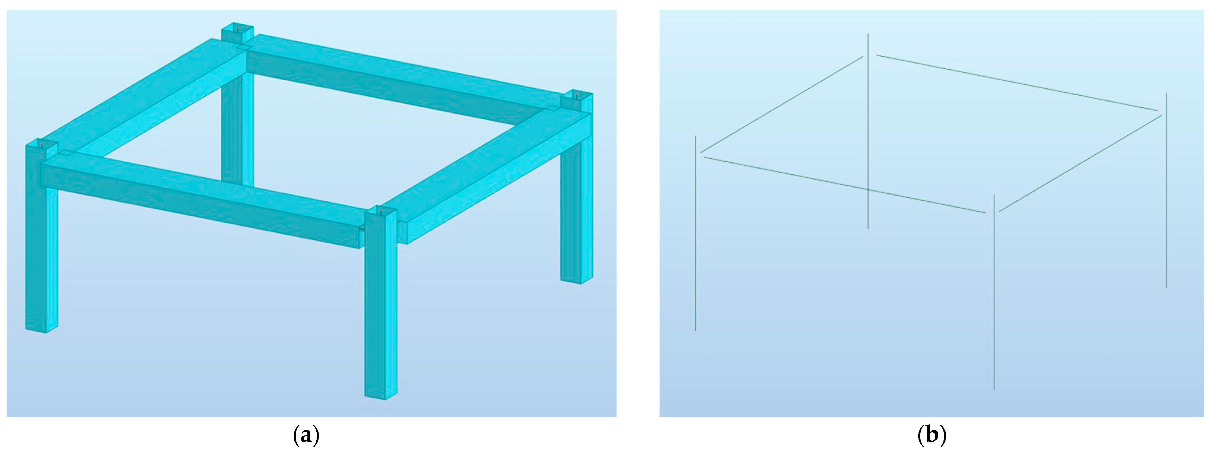
- Edificius. The geometrical model exported from Edificius was correctly imported into the other CAD systems, and the same considerations applied as before (only the material name was associated with the objects, so a separated assignment was then required, as was also the case for the self-test). In the self-test, no section size and element dimension could be edited. In ArchiCAD, only the beam section sizes could be directly modified but not the beam length. For the vertical interoperability (CAD-to-CAE), looking at the benchmark results, the model was correctly imported only in Edilus (from the same company) and Tekla Structures. Shrunk elements in the wrong locations could be observed in SAP2000 and RSA (Figure 5). RFEM and SAP2000 completely failed to import the model: an empty model appeared (with only data about the section type in SAP2000).
5.2. Use of IFC 2x3 Structural Analysis View (SAV)
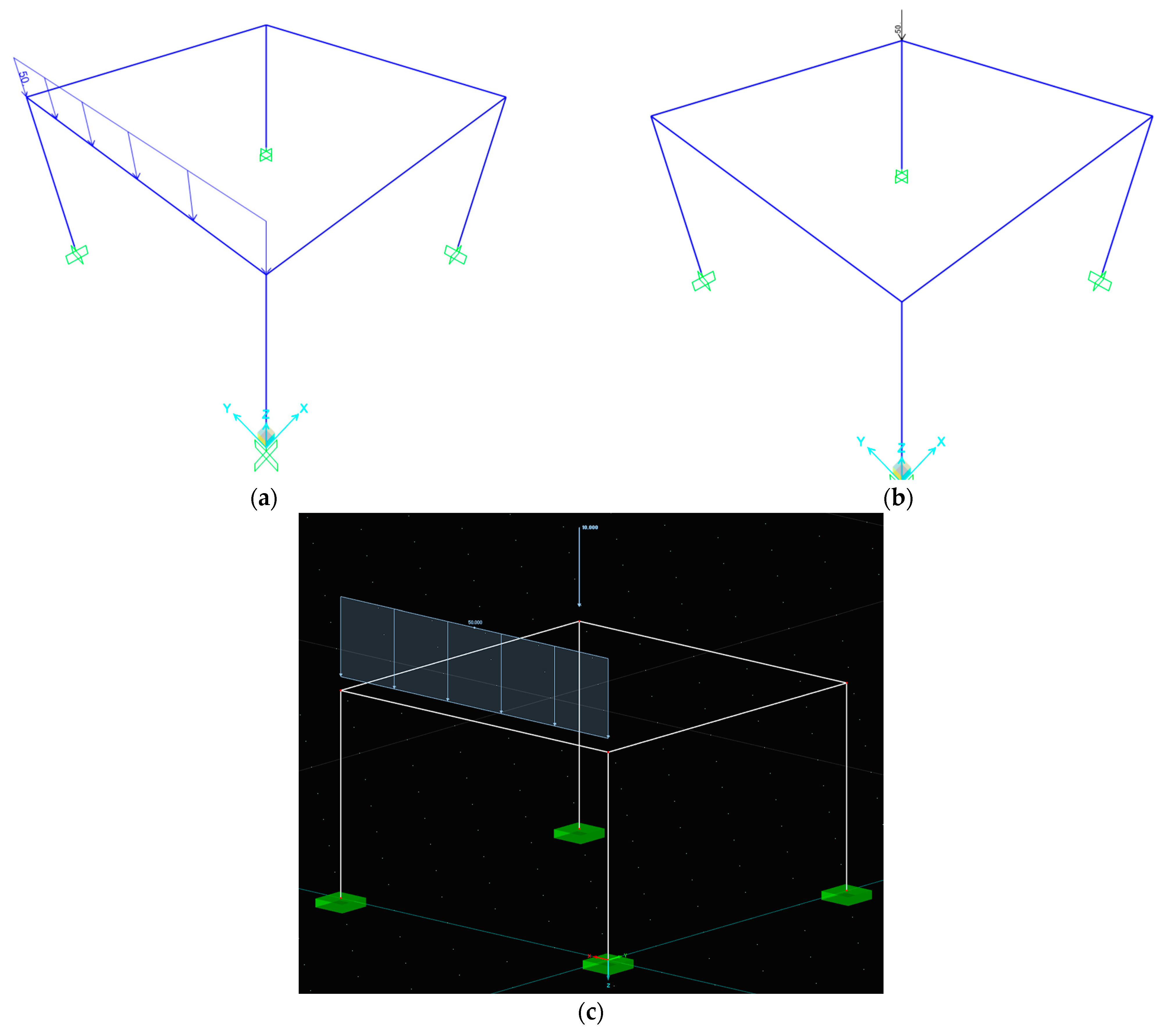
In this part of the study, IFC 2x3 CV 2.0 was again tested, but the attention was focused on the exchange of structural analysis information. The benchmark model was changed according to the information to be tested, i.e., the analytical model including data about constraints and loads (a frame load of 50 kN/m and a point load of 25 kN), which were defined directly in the sender CAE software.
The study was limited to only the sending software SAP2000 and RFEM that could export/import in the IFC 2x3 SAV format. ModeSt had the possibility to export/import in this format, but the trial version used in the current study was limited to the import task only. Table 7 reports the results of the IFC 2x3 SAV benchmark.
In summary, the analytical models with all boundary conditions were generated in RFEM and SAP2000 (Figure 6) and then exported into ModeSt, RFEM, and SAP2000. The self-tests worked well for both RFEM and SAP2000. ModeSt was unable to import restraints and loads from both RFEM and SAP2000, while only the loads were lost in RFEM from the model generated in SAP2000. No problems were found for RFEM to SAP2000.
5.3. Use of IFC 4 Design Transfer View (DTV)
This section reports the results of the tests using the IFC 4 format with the Design Transfer View (DTV) schema. The same native geometric model as is represented in Figure 1 was exported in the IFC 4 DTV format and then imported into the CAD/CAE environments. According to Table 3 and Table 4, not all programs could import/export the IFC 4 format, so the test was limited to a few combinations. These tests were conducted to assess the possibility of using IFC 4 to overcome the issues mentioned above, related to IFC 2x3. Table 8 and Table 9 report the results. All the exported models were validated with BIMvision.
- Revit. In general, there were no significant differences between IFC 4 DTV and IFC 2x3 CV 2.0. The self-test was still not completely successful because of the change of total entity number depending on the self-test sequence and the loss of the original ifcBeam and ifcBeamType entities in the first self-test round. In addition, Tekla Structures correctly imported the model, but as a single block instead of separated elements. Consequently, the imported model was not modifiable in terms of the properties and geometries but was represented only as a reference model. The same behaviour occurred for ArchiCAD and Allplan towards Tekla. RFEM reported an error, stating that IfcColumn and IfcBeam were entities that could not be imported: only analytical elements were expected, e.g., IfcStructuralCurveMember, which is able to describe edge members (straight or curved), such as beams, columns, rods etc.
- ArchiCAD. The same considerations were true for ArchiCAD for the horizontal interoperability: the geometrical model was correctly imported, but a few parameters (section sizes or dimensions) were not always editable. The same behaviour was exhibited for CAE software receiving the IFC 4 model generated in ArchiCAD as for the IFC 2x3 model. In SAP2000, beams were rotated 90° around their axis.
- Allplan. Allplan could export/import in the IFC 4 format in the last release (B) we tested, but was unable to import in that format in the first release, A. For the export format, the same considerations as for IFC 2x3 applied. In RFEM, although the software could import IFC 4 files in release A, an error message appeared while reading the IFC file and no data was imported. In release B, the same software could read the model, but inaccurate positions for the columns and beams were generated, so a poor score was assigned to this test (Figure 7), as was true for IFC 2x3, reported in Figure 4.
An additional test was carried out to verify how the CAD software was able to interpret the information received from the CAE environments in the IFC 4 DTV format. Taking into consideration Table 3 and Table 4, the only CAE software capable of exporting the IFC 4 DTV format was SAP2000. Table 10 reports the results of the last import test in the CAD software compatible with the format for both release A and release B. The comparison between release A and B displayed an improvement in the performance of the data transfer over time; data related to the geometry, the cross shape, the dimensions, and the insertion point were, indeed, correctly transferred and processed by the release B CAD receiving software.
An issue was still observed in the material data transfer, since in this case the label was correctly transferred to the receiving software, but all the structural and physical properties were lost. It is worth noting that in all cases, the entities could be manipulated and changed in the receiving CAD environment, enabling the implementation of an effective optimisation of the design process. Revit reconstructed the imported model well but could not modify the elements. ArchiCAD, on the other hand, could correctly import the geometrical model from SAP2000 and all elements were editable. Allplan and Edilus in the release A version were not compatible with the IFC 4 DTV format. The current release B of the Edilus software package maintains such a limitation; conversely, this issue has been fixed in the renewed version of Allplan. A final comment can be devoted to the performance of RSA and ModeSt, which lacked interoperability based on the IFC 4 schema both in input and output operations; the case of Edificius was better, with the software in this case being able to read IFC 4 files but unable to export in the same format, thus limiting the required interoperability of the design process.
5.4. More on Self-Testing
According to the buildingSMART recommendations for IFC certification, self-tests are suggested but not mandatory. However, it is worth considering that all the information included in the IFC schema was correctly read and interpreted by the software that originated the IFC file. On the other hand, many self-tests performed in the study failed because the mapping procedure gave different outputs in the case of repetitive self-tests.
In order to shed light on this issue and collect all the entities of the IFC file and their attributes at once, the IFC File Analyzer Software by NIST [48] was adopted. The output of each run was a spreadsheet file organised in worksheets that collected each type of entity in the IFC file. Moreover, in a summary worksheet, the entities were grouped and indicated by colour (for example, the entities related to parametric profiles and extrusions were in green, the properties were in yellow, the representation type was in purple, and so on). In the following paragraph, the attention is placed on the results of the repetitive self-tests carried out using all the analysed software packages, looking at the different mapping structures resulting from the exchange tasks.
Revit and Edificius were the software packages that, compared with the others, mapped the entities in different ways during the repetitive self-tests (completing four self-tests before stability was reached in the list of entities appearing in the IFC file). For both systems, the number of IFC entities increased, as well as the file size. In particular, in Revit, for both IFC2x3 and IFC4, IfcBeam only appeared in the first output IFC file, while it was converted into a much more general IfcBuildingElementProxy entity in the later exchanges with the associated IfcMappedItem representation, which enabled a representation to be used as a representation item in one or more other representations (ISO/CD 10303-43:1992). The property information captured in IfcPropertySet also changed and increased, as well as the IfcAxis2Placement3D entities related to a local coordinate system. The columns were originally classified as IfcColumn, and no changes occurred in the subsequent tests. In Edificius, the original IfcColumn and IfcBeam entities were all converted into IfcBuildingElementProxy after the first self-test and were mapped in the same way in the repetitive tests, but the overall number of entities was higher than in other systems, as well as the file size. In ArchiCAD, the self-test worked well, as the mapping stayed invariant for both IFC 2x3 and IFC 4. In AllPlan, the mapping preserved the main information, but the file size increased for the additional data on IfcCartesianPoint in IFC 2x3 alone (indicating a different decomposition of the domain), while no issue appeared with IFC 4. For all the CAE packages, no changes occurred during the repetitive self-tests.
6. On the Connections between Elements in an IFC-Based Structural Model
One of the key aspects of the structural analysis of a structure is the ability to manage the links between the elements. The accuracy of the jointed nodes between the elements guarantees that the structural analysis of the analytical model can be run correctly. This section deals with the ability of BIM-based CAE software to correctly read the spatial location of an element and its connection with the surrounding elements. The goal was to meet the need in the structural analysis to have CAE-to-CAE interoperability for the model to validate the results obtained from the analyses. Due to the strong incompatibility of the software tools with the IFC 4 SAV format, as highlighted in Table 3 and Table 4, the study was conducted by taking into consideration the most common IFC format, IFC 2x3 CV 2.0.
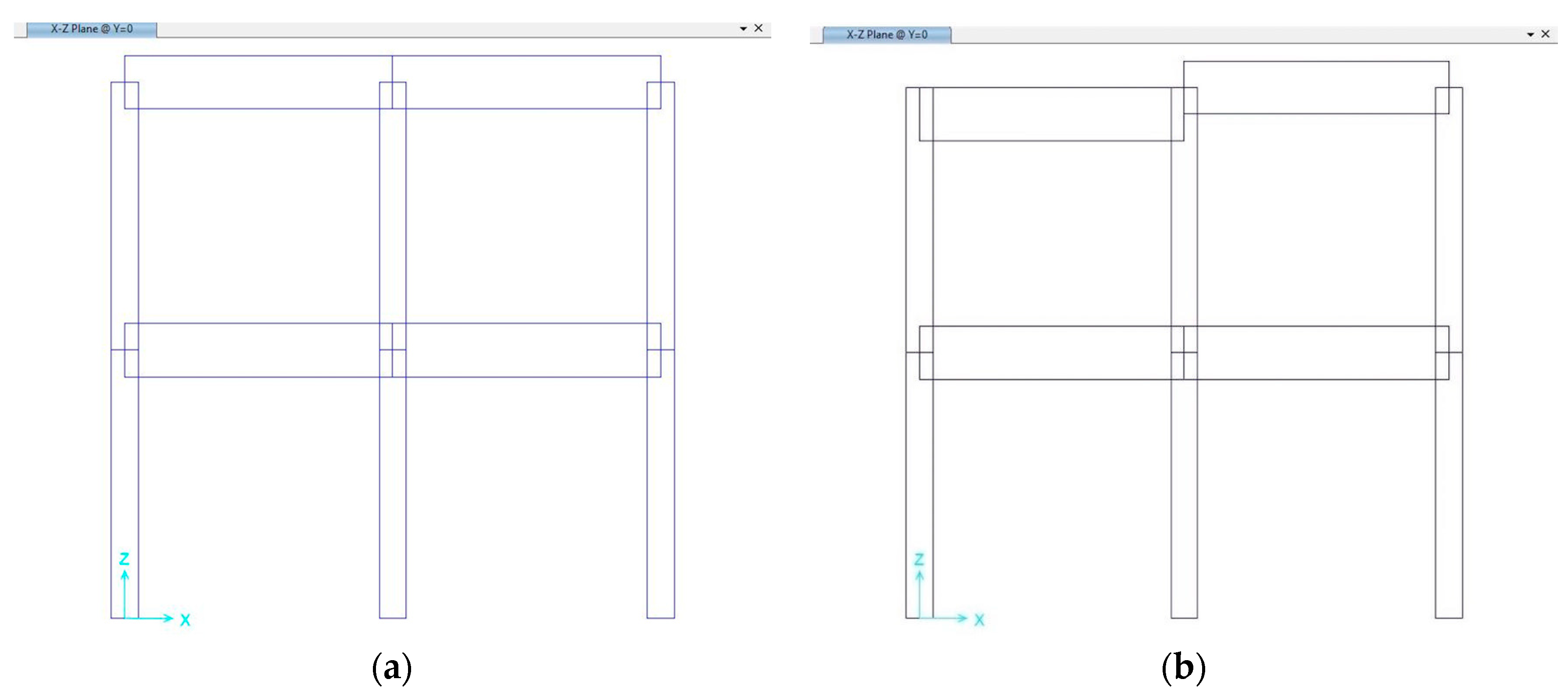
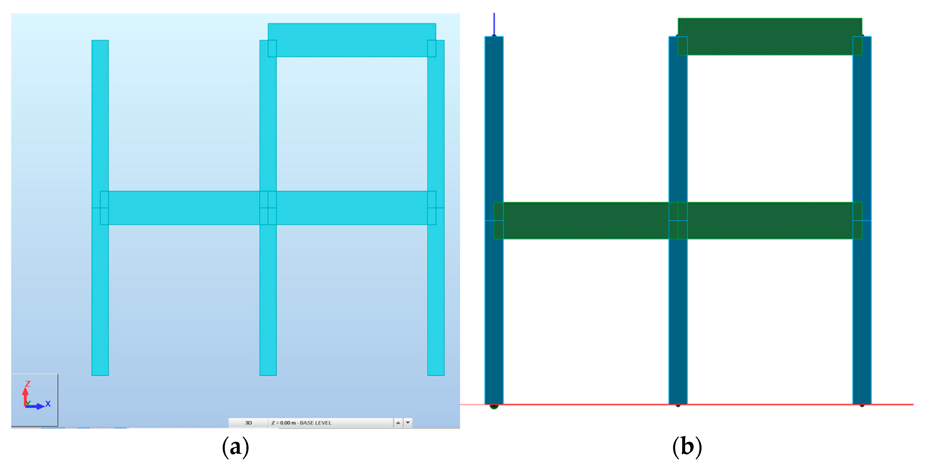
The original model was generated in the SAP2000 software (Figure 8a) using the default (central) location of the axis. Then, as shown in Figure 8b, the position of the upper right beam was changed using the insertion point command. The reference axis of the analytical model remained unchanged, while the frame insertion point was assigned to the top centre (in B).
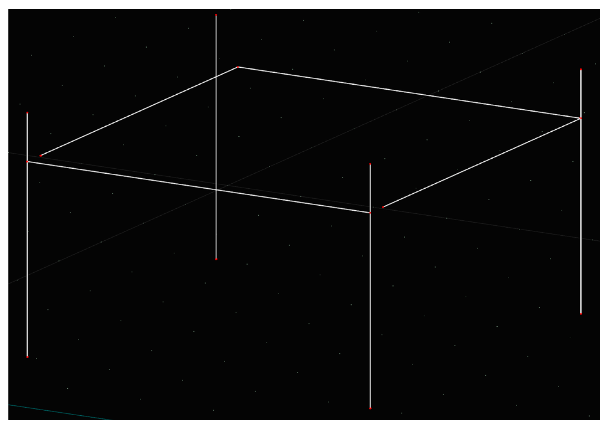
This model was exported into the selected CAD (Revit and ArchiCAD) and CAE (RSA, SAP2000, and ModeSt) software. The accuracy of the model was first validated by checking all the entities in the BIMvision viewer, specifically, the information on the insertion point (Figure 9), meaning that the IFC 2x3 CV 2.0 format was able to preserve and transfer the information about the insertion point.
Nevertheless, RSA and ModeSt were unable to read the beam element with the different insert point (Figure 10): the beam was completely missing, and an error message related to the IfcDerivedProfileDef entity appeared. Conversely, CAD software such as Revit and ArchiCAD correctly imported the IFC model generated in SAP2000 (Figure 11).
Thus, while the information about the different location of the beam was listed in the IFC 2x3 CV 2.0 format, the problem occurred in the inaccurate mapping procedure of the IFC import module of the CAE software. By comparing the contents of the IFC files generated in SAP2000 from the same model, with and without the application of the insertion point on the beam element (Table 11), it could be noted that the additional information related to the modified beam (entities #147 #148 #149), which included the IfcDerivedProfileDef item, was reported in the error messages of ModeSt. The IfcDerivedProfileDef item defined the profile by the transformation from the parent profile [17]. The CAE software was not able to interpret the original profile, causing the total loss of the information. The different positioning of the axis in the analytical model was dissociated from the beam element.
7. Discussion of the Results
This study demonstrated, by means of a very simple model, some of the limitations of the IFC protocol. Amongst these was the issue of data exchange, where, in many cases, the model exchanged via IFC did not keep all of the initially inherited data. In some cases, these reported issues could be easily solved by the receiving-end software, whereas in other cases more effort was required, and in some cases the model was completely useless.
As described in this study, IFC 2x3 CV V2.0 objects could be represented in multiple ways. For example, the column object was exported as ‘SweptSolid’ geometry (the same as for the beam) from Archicad, whereas it was exported as ‘MappedRepresentation’ from Revit (while the beam was exported as ‘SweptSolid’). Moreover, some software, such as RFEM, imported elements only as ‘SweptSolid’ geometry. For example, ‘MappedRepresentation’ allowed for reusing the geometry definition of the column type for all occurrences of the same type.
Therefore, in some of the possible scenarios of CAD-to-CAE data exchange, it is suggested to export the architectural model directly. Specifically, the model must be exported as an analytical model to be imported into the CAE software. Following this process, the mapping procedure is straightforward, and several mapping issues are overcome.
According to the BIM methodology, each object should be classified to be able to exchange it with the correct interpretation. Classical objects are columns, beams, walls, stairs, slabs, etc., and the software applications offered a library of standard parametric components to speed up the design phase. Additional objects could be modelled, even in a parametric way, with any shape and eventually classified as standard objects (i.e., a ‘SweptSolid’ with a custom section classified as a column). When the customised object was exported into the CAD software, its geometrical shape was usually correctly recreated (though not necessarily its original classification), whereas, if exported into a CAE software, the reference to its “natural” classification was often lost, and that object was not recognised or even not imported in the receiving system.
The IFC mapping procedures adopted by many software houses rely only on standard classifications or on a limited set of possible variants provided by the standard, and the end user is asked to edit the geometries and mapping assignments, so the data exchange process is not automatic at all. In this context, there is a useful solution available in a few software tools that provides the possibility to customise the property sets of the translation task for exchanging the original model into a known mapping schema of the receiving software.
A common problem that was observed in all of the tests we performed was related to the material information attributed to the object. In most cases, only the material name was passed through the IFC. The customised properties of a material, defined in the software, were never transferred via IFC (except for ArchiCAD and AllPlan), even though both the IFC 2x3 and IFC 4 standards had the IfcMaterial (and the related PsetMaterial properties) structure, which was capable of incorporating all the useful information.
The level of interoperability achieved via IFC 2x3 was good enough in many cases, in terms of the geometry exchange (less so in terms of the properties exchange and the ability to parametrically edit the size and location of the elements) between the CAD systems. More issues were found when working with the CAE software, where elements could be lost or incorrectly imported. The user was still required to put in a strong effort to generate the correct analytical model ready for the structural analysis. Consider, for example, the reworking necessary to connect the beams and columns that appeared disjointed, or to amend the missing elements when a non-central axis position of the beam was set.
Common manual procedures to connect beams and columns involve the use of trim/extend tools, which can be a very time-consuming task in a large project. In some cases, the end user could find it easier to generate a new analytical model than to extract it from the BIM model.
The interpreted-information-exchange (IIE) mechanism proposed in [23,32] can automate the additions and modifications required for engineering models imported from the BIM model.
The present study also drew attention to the exporting capabilities. It is currently impossible to export, via IFC SAV, the structural analysis results (stress, strain, deformation, etc.), in spite of the fact that the IFC architecture is prepared with entities such as IfcStructuralAction and IfcStructuralActivity. The boundary conditions in structural data (constraints, loads, load combinations, etc.) could be exchanged through the IFC 2x3 SAV. Good results were achieved for this process using this MVD, which is unfortunately still not widely supported.
A discussion about the IFC 4 format is warranted at this stage. Despite the fact that the IFC 4 format was released in 2016, only a few programs actually support it, as shown in Table 4. In addition, in several cases, software packages claim the ability to deal with IFC 4 even in the absence of an official certification by buildingSMART.
For horizontal interoperability, this study reported a generally satisfactory result. However, for vertical interoperability, the results were less than satisfactory and showed serious faults. Excluding the software that did not support the IFC 4 format, the software we studied showed widespread entity-interpretation problems, making the model completely unusable in some cases.
Finally, it was shown that the CAE-to-CAD data exchange in the IFC 4 DTV format is not yet efficient. This limits the design process, because any changes applied in the structural analysis phase cannot be returned directly to the CAD software; the end user needs to manually edit the architectural model based on the structural results. For all the aforementioned issues, in many design contexts, there is growing interest among software manufacturers in using a direct translation solution in the form of plug-in, as it is considered the preferable way to assure interoperability, at least between two software tools.
8. Concluding Remarks
National and international regulatory authorities are driving the AEC world towards integrated digitalisation, whose primary feature is interoperability.
In this paper, NL procedures were thoroughly analysed with particular attention paid to the data exchange between CAD and CAE environments. This was achieved by considering an example of a simple structure consisting of monodimensional members (beams and columns). The analysis was conducted in the context of a BIM-oriented interoperability scenario, based on neutral IFC standards. The data-exchange capabilities of four commercial CAD and six CAE software packages were assessed by referring to two of the most common IFC schemas, namely, IFC 2x3 and IFC 4. A comparison was made based on a grid of evaluation criteria by considering the amount of transferred data, the amount of missing data, the loss of parameterisation, and the possibility of easily editing the received model.
The results of the assessment were not completely satisfactory from an operational standpoint, since the implementation of IFC was not able to ensure the full data exchange, primarily towards CAE software. However, an improvement could be accomplished by exporting the architectural model directly into the analytical model. This was only possible if it was supported by the software, thus overcoming the mapping procedures adopted by the translators.
Finally, additional research and development are needed to deliver software products with viable mechanisms of interoperability. Moreover, interoperability must be complemented with the development of clear and strict guidelines for dealing with data. Specifically, these data should encompass the set of standard elements, such as the widely used monodimensional beam and column members.
Author Contributions
Conceptualisation, S.G. and G.F.; methodology, S.G. and G.F.; formal analysis, L.C.; data curation, S.G.; original draft preparation, S.G. and G.F.; writing—review and editing, S.G., L.C., G.F. and C.R.; supervision, S.G., G.F. and C.R.; funding acquisition, S.G. and G.F. All authors have read and agreed to the published version of the manuscript.
Funding
This research received no external funding.
Acknowledgments
The authors are grateful to Gabriele Testa and Davide Di Leva for their helpful support in the execution of the different tests reported in this paper.
Conflicts of Interest
The authors declare no conflict of interest.
Disclosure Statement
Authors declare that they do not have any competing financial, professional, or personal interests from other parties.
References
- Maunula, A.; Smeds, R.; Hivernsalo, A. Implementation of Building Information Modeling (BIM)—A process perspective. In Proceedings of the APMS 2008 Innovations in Networks, Helsinki University of Technology, Espoo, Finland, 17 September 2008; pp. 379–386. [Google Scholar]
- Eastman, C.; Teicholz, P.; Sacks, R.; Liston, K. BIM Handbook: A Guide to Building Information Modeling for Owners, Managers, Designers, Engineers and Contractors, 2nd ed.; John Wiley & Sons: Hoboken, NJ, USA, 2011. [Google Scholar]
- Liao, L.; Teo, E.A.L. Critical success factors for enhancing the building information modelling implementation in building projects in Singapore. J. Civ. Eng. Manag. 2017, 23, 1029–1044. [Google Scholar] [CrossRef] [Green Version]
- Directive (EU) 2015/1535 of the European Parliament and of the Council of 9 September 2015 Laying Down a Procedure for the Provision of Information in the Field of Technical Regulations and of Rules on Information Society Services; Official Journal of the European Union, L241; EU Publications Office: Luxembourg, 2015.
- Ministerial Decree 27 January 2017, n. 560. Modalità e i Tempi di Progressiva Introduzione dei Metodi e Degli Strumenti Elettronici di Modellazione per l’edilizia e le Infrastrutture. Rome, Italy. 2017; (In Italian). Available online: https://www.mit.gov.it/normativa/decreto-ministeriale-numero-560-del-01122017 (accessed on 17 September 2021).
- Ministerial Decree 8 August 2021, n. 312. Modifiche al Decreto del Ministero delle Infrastrutture e dei Trasporti 1° Dicembre 2017, n. 560 Che Stabilisce le Modalità e i Tempi di Progressiva Introduzione dei Metodi e degli Strumenti Elettronici di Modellazione per l’edilizia e le Infrastrutture. Rome, Italy. 2018; (In Italian). Available online: https://www.mit.gov.it/node/16280 (accessed on 16 September 2021).
- Noardo, F.; Arroyo Ohori, K.; Krijnen, T.; Stoter, J. An Inspection of IFC Models from Practice. Appl. Sci. 2021, 11, 2232. [Google Scholar] [CrossRef]
- Bastos Porsani, G.; Del Valle de Lersundi, K.; Sánchez-Ostiz Gutiérrez, A.; Fernández Bandera, C. Interoperability between Building Information Modelling (BIM) and Building Energy Model (BEM). Appl. Sci. 2021, 11, 2167. [Google Scholar] [CrossRef]
- Chiaia, B.; Davardoust, S.; Osello, A. Structural calculations by horizontal and vertical interoperability for the redevelopment of existing buildings. In Proceedings of the XIII International Forum Heritage and Technology, Aversa, Italy, 11–13 June 2015; pp. 650–658. [Google Scholar]
- Bianconi, F.; Conti, P.; Di Angelo, L. Interoperability among CAD/CAM/CAE systems: A review of current research trends. In Proceedings of the Geometric Modeling and Imaging—New Trends (GMAI’06), London, UK, 5–7 July 2006; pp. 82–89. [Google Scholar] [CrossRef]
- Xu, X. Integrating Advanced Computer-Aided Design, Manufacturing, and Numerical Control: Principles and Implementations; IGI Global: Hershey, PA, USA, 2009. [Google Scholar] [CrossRef]
- Aldegeily, M.; Hu, Y.; Shao, X.; Zhang, J. From architectural design to structural analysis: A data-driven approach to study Building Information Modeling (BIM) interoperability. In Proceedings of the 54th ASC Annual International Conference, Associated Schools of Construction, Minneapolis, MN, USA, 18–21 April 2018; pp. 537–545. [Google Scholar]
- Sibenik, G.; Kovacic, I. Assessment of model-based data exchange between architectural design and structural analysis. J. Build. Eng. 2020, 32, 101589. [Google Scholar] [CrossRef]
- IFC2x3 Coordination View Version 2.0 Certification—Workflow Description. T. Liebich, K. Hausknecht, AEC3 Editors, ver. 1.1. 2010. Available online: https://standards.buildingsmart.org/documents/bSI_IFC_Certification_2-0_Workflow_CV-V2.0_Draft1.1.pdf (accessed on 17 September 2021).
- ISO 10303-21:2016 (International Organization for Standardization). Industrial Automation Systems and Integration—Product Data Representation and Exchange, Part 21; International Organization for Standardization: Geneva, Switzerland, 2016. [Google Scholar]
- Osello, A. Implementation of BIM Methodology for District Data Visualization. Master’s Thesis, Politecnico di Torino, Torino, Italy, 2017. (In Italian). Available online: https://webthesis.biblio.polito.it/6408/1/tesi.pdf (accessed on 15 October 2021).
- buildingSMART International. Available online: https://technical.buildingsmart.org/standards/ifc/ifc-schema-specifications/ifc-release-notes/ (accessed on 17 September 2021).
- buildingSMART International. Certified Software. Available online: https://www.buildingsmart.org/compliance/software-certification/certified-software/ (accessed on 17 September 2021).
- buildingSMART International. IFC Specifications Database. Available online: https://technical.buildingsmart.org/standards/ifc/ifc-schema-specifications/ (accessed on 17 September 2021).
- Golabchi, A.; Kamat, V.R. Evaluation of industry foundation classes for practical building information modeling interoperability. In Proceedings of the 30th ISARC, Montreal, QC, Canada, 11–15 August 2013; pp. 17–26. [Google Scholar]
- Lee, G.; Won, J.; Ham, S.; Shin, Y. Metrics for Quantifying the Similarities and Differences between IFC Files. J. Comput. Civil. Eng. 2011, 25, 172–181. [Google Scholar] [CrossRef]
- buildingSMART International, Coordination View Version 2.0 Summary. Available online: http://technical.buildingsmart.org/certification/ifc2x3-program (accessed on 17 September 2021).
- Ramaji, I.J.; Memari, A.M. Interpretation of structural analytical models from the coordination view in Building information models. Autom. Constr. 2018, 90, 117–133. [Google Scholar] [CrossRef]
- buildingSMART International, Structural Analysis View Summary. Available online: https://standards.buildingsmart.org/MVD/RELEASE/IFC2x3/TC1/Structural/StructuralAnalysisView.zip (accessed on 17 September 2021).
- buildingSMART International, Model View Definition Summary. Available online: https://technical.buildingsmart.org/standards/ifc/mvd/ (accessed on 17 September 2021).
- Lipman, R.; Palmer, M.; Palacios, S. Assessment of conformance and interoperability testing methods used for construction industry product models. Autom. Constr. 2011, 20, 418–428. [Google Scholar] [CrossRef]
- Pazlar, T.; Turk, Z. Interoperability in practice: Geometric data exchange using the IFC standard. J. Inf. Technol. Constr. 2008, 13, 362–380. [Google Scholar]
- Jeong, Y.S.; Eastman, C.M.; Sacks, R.; Kaner, I. Benchmark tests for BIM data exchanges of precast concrete. Autom. Constr. 2009, 18, 469–484. [Google Scholar] [CrossRef]
- Nizam, R.S.; Zhang, C. Current State of Information Exchange between the two most popular BIM software: Revit and Tekla. In Proceedings of the 1st International Conference on Sustainable Building and Structures, Sustainable Building and Structures, Suzhou, China, 29 October–1 November 2015. [Google Scholar]
- Sibenik, G. Building information modelling based interdisciplinary data exchange: A case study. In Proceedings of the 1st International UK BIM Academic Forum Conference, Glasgow, UK, 13–15 September 2016; pp. 379–390. [Google Scholar]
- Taher, A.A. BIM Software Capability and Interoperability Analysis. Master’s Thesis, KTH School of Architecture and the Built Environment (ABE), Civil and Architectural Engineering, Building Technology, Stockholm, Sweden, 2016. Available online: https://www.diva-portal.org/smash/get/diva2:917005/FULLTEXT01.pdf (accessed on 17 September 2021).
- Ramaji, I.J.; Memari, A.M. Interpreted information exchange: Systematic approach for BIM to engineering analysis information transformations. J. Comput. Civ. Eng. 2016, 30, 04016028. [Google Scholar] [CrossRef]
- Muller, M.F.; Garbers, A.; Esmanioto, F.; Huber, N.; Loures, E.R.; Canciglieri, O., Jr. Data interoperability assessment though IFC for BIM in structural design—A five-year gap analysis. J. Civ. Eng. Manag. 2017, 23, 943–954. [Google Scholar] [CrossRef]
- Lai, H.; Deng, X. Interoperability analysis of IFC-based data exchange between heterogeneous BIM software. J. Civ. Eng. Manag. 2018, 24, 537–555. [Google Scholar] [CrossRef]
- Marcolin, G. Structural Information Modeling Proposta di Sviluppo di Standard Informative Open BIM per l’integrazione di Analisi Strutturali. Master’s Thesis, University of Padua, Department of Civil, Environment and Architectural Engineering, Padua, Italy, 2017. (In Italian). Available online: http://tesi.cab.unipd.it/56332 (accessed on 17 September 2021).
- Revit 2021, Computer Software; Autodesk Inc.: San Rafael, CA, USA, 2020.
- Allplan 2020, Computer Software; Allplan GmbH: Munich, Germany, 2020.
- ArchiCAD 24, Computer Software; Graphisoft: Budapest, Hungary, 2020.
- Edificius 14, Computer Software; Acca Software, S.p.A.: Bagnoli Irpino, Italy, 2020.
- Robot Structural Analysis 2021, Computer Software; Autodesk Inc.: San Rafael, CA, USA, 2020.
- Tekla Structures 2020, Computer Software; Trimble Solutions Corporation: Helsinki, Finland, 2020.
- ModeSt 8.23, Computer Software; Tecnisoft s.a.s.: Prato, Italy, 2020.
- RFEM 5.23, Computer Software; Dlubal Software GmbH: Tiefenbach, Germany, 2020.
- SAP2000 22, Computer Software; Computers and Structures, Inc. (CSIAMERICA): Berkeley, CA, USA, 2020.
- Edilus 44, Computer Software; Acca Software, S.p.A.: Bagnoli Irpino, Italy, 2020.
- Gerbino, S.; Brondi, A. Interoperability issues among cad systems: A benchmarking study of 7 commercial MCAD software. In Proceedings of the 8th International Design Conference—Design, Dubrovnik, Croatia, 18–21 May 2004. [Google Scholar]
- BIMvision 2.24, Computer Software; Datacomp Sp. z.o.o.: Krakov, Poland, 2020.
- Lipman, R. IFC File Analyzer Software. J. Res. Natl. Inst. Stand. Technol. 2017, 122. [Google Scholar] [CrossRef]
Figure 1.
View of the simple model created in Revit used for the benchmark.

Figure 2.
Snapshots of the resulting orientation of the beams (a) and of disjointed nodes (b), in RSA from Autodesk Revit.
Figure 2.
Snapshots of the resulting orientation of the beams (a) and of disjointed nodes (b), in RSA from Autodesk Revit.

Figure 3.
Snapshot of the imported model in SAP2000, from Allplan.

Figure 4.
Snapshot of the imported model in RFEM, from Allplan.

Figure 5.
Snapshots of the imported model in SAP2000 (a) and RSA (b) from Edificius.

Figure 6.
Analytical models generated in SAP2000 (a,b) and RFEM (c).

Figure 7.
Top view of the inaccurate model imported in RFEM from Allplan via IFC 4.

Figure 8.
Views of the model in SAP2000: (a) centroid beams model; (b) top center beam model.

Figure 9.
Front view of the IFC model in BIMvision.

Figure 10.
Missing beam in RSA (a) and ModeST (b).

Figure 11.
Top centre model imported into Revit in IFC 2x3 CV v2.0.


Table 1.
Overview of studies on data interoperability involving structural analysis and design.
| Criteria | Geometry | Material | Dimension | Section Type | |
|---|---|---|---|---|---|
| IFC MVD | |||||
| IFC 2x Add1 | Extended Geometric View | Pazlar and Turk [27] | |||
| IFC 2x3 | Coordination View 2.0 | Aldegeily et al. [12] Sibenik and Kovacic [13] Jeong et al. [28] Nizam and Zhang [29] Sibenik [30] Taher [31] Ramaji and Memari [32] Muller et al. [33] Lai and Deng [34] | Jeong et al. [28] Taher [31] Ramaji and Memari [32] Muller et al. [33] Lai and Deng [34] | Sibenik and Kovacic [13] Jeong et al. [28] Sibenik [30] Taher [31] Ramaji and Memari [32] Lai and Deng [34] | Jeong et al. [28] Nizam and Zhang [29] Taher [31] Ramaji and Memari [32] Lai and Deng [34] |
| Assessed herein | Assessed herein | Assessed herein | Assessed herein | ||
| Structural Analysis View | Ramaji and Memari [32] Marcolin [35] | Aldegeily et al. [12] Ramaji and Memari [32] Marcolin [35] | Ramaji and Memari [32] Marcolin [35] | Aldegeily et al. [12] Ramaji and Memari [32] Marcolin [35] | |
| Assessed herein | Assessed herein | Assessed herein | Assessed herein | ||
| IFC 4 | Reference View | Chiaia et al. [9] | |||
| Design Transfer View | Assessed herein | ||||
| Structural Analysis View | Marcolin [35] Assessed herein | ||||
Table 2.
List of software packages adopted for the BIM tests.
| Platform | Company | Software | Version (A) | Version (B) | Website | Ref. |
|---|---|---|---|---|---|---|
| CAD | Autodesk | REVIT | 2017 | 2021 | www.autodesk.com | [36] |
| NEMETSCHEK | Allplan | 2017 | 2020 | www.allplan.com | [37] | |
| Graphisoft | ArchiCAD | 2017 | 24 | www.graphisoft.com | [38] | |
| ACCA Software S.P.A. | Edificius | 2017 | 2020 | www.acca.it | [39] | |
| CAE | Autodesk | Robot Structural Analysis | 2017 | 2021 | www.autodesk.com | [40] |
| Trimble Solutions Corporation | Tekla Structures | 2018 | 2020 | www.tekla.com | [41] | |
| Tecnisoft s.a.s. | ModeSt | 8.15 | 8.23 | www.tecnisoft.it | [42] | |
| Dlubal Software | RFEM | 5.14.02 | 5.23 | www.dlubal.com | [43] | |
| CSI | SAP2000 | 19.2.1 | 22 | www.csi-italia.eu | [44] | |
| ACCA Software S.P.A. | Edilus | 2017 | 2020 | www.acca.it | [45] |
Table 3.
Supported IFC import format in CAD/CAE software.
| Formats | IFC 2X3 | IFC 4 | |||||||||
|---|---|---|---|---|---|---|---|---|---|---|---|
| MVD Software | Coordination View 2.0 | Structural Analysis View | Reference View | Design Transfer View | Structural Analysis View | ||||||
| A | B | A | B | A | B | A | B | A | B | ||
| CAD | Revit | ☑⎕ | ☑⎕ | ✖⎕ | ✖⎕ | ☑⎕ | ☑⎕ | ☑⎕ | ☑⎕ | ✖⎕ | ✖⎕ |
| Allplan | ☑⎕ | ☑⎕ | ☑⎕ | ☑⎕ | ✖⎕ | ☑⎕ | ✖⎕ | ☑⎕ | ✖⎕ | ✖⎕ | |
| ArchiCAD | ☑⎕ | ☑⎕ | ✖⎕ | ☑⎕ | ☑⎕ | ☑⎕ | ☑⎕ | ☑⎕ | ✖⎕ | ✖⎕ | |
| Edificius | ☑⎕ | ☑⎕ | ✖⎕ | ☑⎕ | ☑⎕ | ☑⎕ | ☑⎕ | ☑⎕ | ✖⎕ | ☑⎕ | |
| CAE | RSA | ☑⎕ | ☑⎕ | ✖⎕ | ✖⎕ | ✖⎕ | ✖⎕ | ✖⎕ | ✖⎕ | ✖⎕ | ✖⎕ |
| Tekla Structures | ☑⎕ | ☑⎕ | ✖⎕ | ✖⎕ | ☑⎕ | ☑⎕ | ☑⎕ | ☑⎕ | ✖⎕ | ✖⎕ | |
| ModeSt | ☑⎕ | ☑⎕ | ☑⎕ | ☑⎕ | ✖⎕ | ✖⎕ | ✖⎕ | ✖⎕ | ✖⎕ | ✖⎕ | |
| RFEM | ☑⎕ | ☑⎕ | ☑⎕ | ☑⎕ | ☑⎕ | ☑⎕ | ☑⎕ | ☑⎕ | ✖⎕ | ☑⎕ | |
| SAP2000 | ☑⎕ | ☑⎕ | ☑⎕ | ☑⎕ | ☑⎕ | ☑⎕ | ☑⎕ | ☑⎕ | ☑⎕ | ☑⎕ | |
| Edilus | ☑⎕ | ☑⎕ | ✖⎕ | ☑⎕ | ☑⎕ | ☑⎕ | ☑⎕ | ☑⎕ | ✖⎕ | ☑⎕ | |
Table 4.
Supported IFC export format in CAD/CAE software.
| Formats | IFC 2X3 | IFC 4 | |||||||||
|---|---|---|---|---|---|---|---|---|---|---|---|
| MVD Software | Coordination View 2.0 | Structural Analysis View | Reference View | Design Transfer View | Structural Analysis View | ||||||
| A | B | A | B | A | B | A | B | A | B | ||
| CAD | Revit | ☑⎕ | ☑⎕ | ✖⎕ | ✖⎕ | ☑⎕ | ☑⎕ | ☑⎕ | ☑⎕ | ✖⎕ | ✖⎕ |
| Allplan | ☑⎕ | ☑⎕ | ☑⎕ | ☑⎕ | ☑⎕ | ☑⎕ | ☑⎕ | ☑⎕ | ✖⎕ | ✖⎕ | |
| ArchiCAD | ☑⎕ | ☑⎕ | ✖⎕ | ☑⎕ | ☑⎕ | ☑⎕ | ☑⎕ | ☑⎕ | ✖⎕ | ✖⎕ | |
| Edificius | ☑⎕ | ☑⎕ | ✖⎕ | ✖⎕ | ✖⎕ | ✖⎕ | ✖⎕ | ✖⎕ | ✖⎕ | ✖⎕ | |
| CAE | RSA | ✖⎕ | ✖⎕ | ✖⎕ | ✖⎕ | ✖⎕ | ✖⎕ | ✖⎕ | ✖⎕ | ✖⎕ | ✖⎕ |
| Tekla Structures | ☑⎕ | ☑⎕ | ✖⎕ | ✖⎕ | ✖⎕ | ☑⎕ | ✖⎕ | ☑⎕ | ✖⎕ | ✖⎕ | |
| ModeSt | ☑⎕ | ☑⎕ | ☑⎕ | ☑⎕ | ✖⎕ | ✖⎕ | ✖⎕ | ✖⎕ | ✖⎕ | ✖⎕ | |
| RFEM | ✖⎕ | ✖⎕ | ☑⎕ | ☑⎕ | ✖⎕ | ✖⎕ | ✖⎕ | ✖⎕ | ✖⎕ | ✖⎕ | |
| SAP2000 | ☑⎕ | ☑⎕ | ☑⎕ | ☑⎕ | ✖⎕ | ✖⎕ | ☑⎕ | ☑⎕ | ☑⎕ | ☑⎕ | |
| Edilus | ☑⎕ | ☑⎕ | ✖⎕ | ✖⎕ | ✖⎕ | ✖⎕ | ✖⎕ | ✖⎕ | ✖⎕ | ✖⎕ | |
Table 5.
Summary of results of CAD-to-CAD interoperability in IFC 2x3 CV 2.0 format.
| Software | Revit | Allplan | ArchiCAD | Edificius | ||||||||||||||||||||||||||||
|---|---|---|---|---|---|---|---|---|---|---|---|---|---|---|---|---|---|---|---|---|---|---|---|---|---|---|---|---|---|---|---|---|
| Geometry | Materials | Section Type | Dimensions | Geometry | Materials | Section Type | Dimensions | Geometry | Materials | Section Type | Dimensions | Geometry | Materials | Section Type | Dimensions | |||||||||||||||||
| A | B | A | B | A | B | A | B | A | B | A | B | A | B | A | B | A | B | A | B | A | B | A | B | A | B | A | B | A | B | A | B | |
| Revit |  | |  | | | |  | | | |  | | | | | | | | | | | | | | | | | |  | | | |
| Allplan | | | | | | | | | | | | | | | | | | | | | | | | | | | | | | | | |
| ArchiCAD | | | | | | | | | | | | | | | | | | | | | | | | | | | | | | | | |
| Edificius | | | | | | | | | | | | | | | | | | | | | | | | | | | | | | | | |
| Symbol legend | Poor | | Fair | | Average | | Good | | Excellent | | ||||||||||||||||||||||
Table 6.
Summary of results of CAD-to-CAE interoperability in IFC 2x3 CV 2.0 format.
| Software | RSA | ModeSt | RFEM | SAP2000 | Edilus | Tekla Structures | ||||||||||||||||||||||||||||||||||||||||||
|---|---|---|---|---|---|---|---|---|---|---|---|---|---|---|---|---|---|---|---|---|---|---|---|---|---|---|---|---|---|---|---|---|---|---|---|---|---|---|---|---|---|---|---|---|---|---|---|---|
| Geometry | Materials | Section Type | Dimensions | Geometry | Materials | Section Type | Dimensions | Geometry | Materials | Section Type | Dimensions | Geometry | Materials | Section Type | Dimensions | Geometry | Materials | Section Type | Dimensions | Geometry | Materials | Section Type | Dimensions | |||||||||||||||||||||||||
| A | B | A | B | A | B | A | B | A | B | A | B | A | B | A | B | A | B | A | B | A | B | A | B | A | B | A | B | A | B | A | B | A | B | A | B | A | B | A | B | A | B | A | B | A | B | A | B | |
| Revit | | | | | | | | | | | | | | | | | | | | | | | | | | | | | | | | | | | | | | | | | | | | | | | | |
| Allplan | | | | | | | | | | | | | | | | | | | | | | | | | | | | | | | | | | | | | | | | | | | | | | | | |
| ArchiCAD | | | | | | | | | | | | | | | | | | | | | | | | | | | | | | | | | | | | | | | | | | | | | | | | |
| Edificius | | | | | | | | | | | | | | | | | | | | | | | | | | | | | | | | | | | | | | | | | | | | | | | | |
| Symbol legend | Poor | | Fair | | Average | | Good | | Excellent | | ||||||||||||||||||||||||||||||||||||||
Table 7.
Summary of results of CAE-to-CAE interoperability in IFC 2x3 SAV format.
| Software | ModeSt | RFEM | SAP2000 | |||||||||||||||||||||
|---|---|---|---|---|---|---|---|---|---|---|---|---|---|---|---|---|---|---|---|---|---|---|---|---|
| Geometry | Materials | Restraints | Loads | Geometry | Materials | Restraints | Loads | Geometry | Materials | Restraints | Loads | |||||||||||||
| A | B | A | B | A | B | A | B | A | B | A | B | A | B | A | B | A | B | A | B | A | B | A | B | |
| RFEM | | | | | | | | | | | | | | | | | | | | | | | | |
| SAP2000 | | | | | | | | | | | | | | | | | | | | | | | | |
| Symbol legend | Poor | | Fair | | Average | | Good | | Excellent | | ||||||||||||||
Table 8.
Summary of results of CAD-to-CAD interoperability in IFC 4 DTV format.
| Software | Revit | Allplan | ArchiCAD | Edificius | ||||||||||||||||||||||||||||
|---|---|---|---|---|---|---|---|---|---|---|---|---|---|---|---|---|---|---|---|---|---|---|---|---|---|---|---|---|---|---|---|---|
| Geometry | Materials | Section Type | Dimensions | Geometry | Materials | Section Type | Dimensions | Geometry | Materials | Section Type | Dimensions | Geometry | Materials | Section Type | Dimensions | |||||||||||||||||
| A | B | A | B | A | B | A | B | A | B | A | B | A | B | A | B | A | B | A | B | A | B | A | B | A | B | A | B | A | B | A | B | |
| Revit | | | | | | | | | NA | | NA | | NA | | NA | | | | | | | | | | | | | | | | | |
| Allplan | | | | | | | | | NA | | NA | | NA | | NA | | | | | | | | | | | | | | | | | |
| ArchiCAD | | | | | | | | | NA | | NA | | NA | | NA | | | | | | | | | | | | | | | | | |
| Symbol legend | Poor | | Fair | | Average | | Good | | Excellent | | ||||||||||||||||||||||
Table 9.
Summary of results of CAD-to-CAE interoperability in IFC 4 DTV format.
| Software | RFEM | SAP2000 | Edilus | Tekla Structures | ||||||||||||||||||||||||||||
|---|---|---|---|---|---|---|---|---|---|---|---|---|---|---|---|---|---|---|---|---|---|---|---|---|---|---|---|---|---|---|---|---|
| Geometry | Materials | Section Type | Dimensions | Geometry | Materials | Section Type | Dimensions | Geometry | Materials | Section Type | Dimensions | Geometry | Materials | Section Type | Dimensions | |||||||||||||||||
| A | B | A | B | A | B | A | B | A | B | A | B | A | B | A | B | A | B | A | B | A | B | A | B | A | B | A | B | A | B | A | B | |
| Revit | | | | | | | | | | | | | | | | | | | | | | | | | | | | | | | | |
| Allplan | | | | | | | | | | | | | | | | | | | | | | | | | | | | | | | | |
| ArchiCAD | | | | | | | | | | | | | | | | | | | | | | | | | | | | | | | | |
| Symbol legend | Poor | | Fair | | Average | | Good | | Excellent | | ||||||||||||||||||||||
Table 10.
Summary of results of CAE-to-CAD interoperability in IFC 4 DTV.
| Software | Revit | Allplan | ArchiCAD | Edificius | ||||||||||||||||||||||||||||
|---|---|---|---|---|---|---|---|---|---|---|---|---|---|---|---|---|---|---|---|---|---|---|---|---|---|---|---|---|---|---|---|---|
| Geometry | Materials | Section Type | Dimensions | Geometry | Materials | Section Type | Dimensions | Geometry | Materials | Section Type | Dimensions | Geometry | Materials | Section Type | Dimensions | |||||||||||||||||
| A | B | A | B | A | B | A | B | A | B | A | B | A | B | A | B | A | B | A | B | A | B | A | B | A | B | A | B | A | B | A | B | |
| SAP2000 | | | | | | | | | NA | | NA | | NA | | NA | | | | | | | | | | NA | | NA | | NA | | NA | |
| Symbol legend | Poor | | Fair | | Average | | Good | | Excellent | | ||||||||||||||||||||||
Table 11.
IFC code lines with the (default) centroid mode (left) and top center mode (right).
| … omitted … #145=IFCCARTESIANPOINT((0.0000000E+000,0.0000000E+000,6.0000000E+000)); #146=IFCEXTRUDEDAREASOLID(#124,#14,#37,3.0000000E+000); #147=IFCBEAM(‘0ong58CG93SOM$rMk9SAek’,#62,’10’,$,$,#149,#150,$); #148=IFCRELASSOCIATESMATERIAL(‘0mODI5fJL9ouABXsV8qtx5’,#3,$,$,(#147),#65); #149=IFCLOCALPLACEMENT($,#151); #150=IFCPRODUCTDEFINITIONSHAPE($,$,(#152)); … omitted … | … omitted … #145=IFCCARTESIANPOINT((0.0000000E+000,0.0000000E+000,6.0000000E+000)); #146=IFCEXTRUDEDAREASOLID(#147,#14,#37,3.0000000E+000); #147=IFCDERIVEDPROFILEDEF(.AREA.,$,#124,#148,$); #148=IFCCARTESIANTRANSFORMATIONOPERATOR2D($,$,#149,$); #149=IFCCARTESIANPOINT((0.0000000E+000,−3.0000001E-001)); #150=IFCBEAM(‘0ong58CG93SOM$rMk9SAek’,#62,’10’,$,$,#152,#153,$); #151=IFCRELASSOCIATESMATERIAL(‘3Vot4K9MbAnuNn56IC3GM4’,#3,$,$,(#150),#65); #152=IFCLOCALPLACEMENT($,#154); #153=IFCPRODUCTDEFINITIONSHAPE($,$,(#155)); … omitted … |
Publisher’s Note: MDPI stays neutral with regard to jurisdictional claims in published maps and institutional affiliations. |
© 2021 by the authors. Licensee MDPI, Basel, Switzerland. This article is an open access article distributed under the terms and conditions of the Creative Commons Attribution (CC BY) license (https://creativecommons.org/licenses/by/4.0/).
Share and Cite
MDPI and ACS Style
Gerbino, S.; Cieri, L.; Rainieri, C.; Fabbrocino, G. On BIM Interoperability via the IFC Standard: An Assessment from the Structural Engineering and Design Viewpoint. Appl. Sci. 2021, 11, 11430. https://doi.org/10.3390/app112311430
AMA Style
Gerbino S, Cieri L, Rainieri C, Fabbrocino G. On BIM Interoperability via the IFC Standard: An Assessment from the Structural Engineering and Design Viewpoint. Applied Sciences. 2021; 11(23):11430. https://doi.org/10.3390/app112311430
Chicago/Turabian StyleGerbino, Salvatore, Luigi Cieri, Carlo Rainieri, and Giovanni Fabbrocino. 2021. "On BIM Interoperability via the IFC Standard: An Assessment from the Structural Engineering and Design Viewpoint" Applied Sciences 11, no. 23: 11430. https://doi.org/10.3390/app112311430
Note that from the first issue of 2016, this journal uses article numbers instead of page numbers. See further details here.